EP2687365A2 - Métaux réfractaires nanostructurés, carbures de métaux, revêtements et pièces fabriqués à partir de ceux-ci - Google Patents
Métaux réfractaires nanostructurés, carbures de métaux, revêtements et pièces fabriqués à partir de ceux-ci Download PDFInfo
- Publication number
- EP2687365A2 EP2687365A2 EP13188147.6A EP13188147A EP2687365A2 EP 2687365 A2 EP2687365 A2 EP 2687365A2 EP 13188147 A EP13188147 A EP 13188147A EP 2687365 A2 EP2687365 A2 EP 2687365A2
- Authority
- EP
- European Patent Office
- Prior art keywords
- refractory metal
- nanoparticles
- surfactant
- metal carbide
- carbide
- Prior art date
- Legal status (The legal status is an assumption and is not a legal conclusion. Google has not performed a legal analysis and makes no representation as to the accuracy of the status listed.)
- Granted
Links
- 239000003870 refractory metal Substances 0.000 title claims abstract description 362
- 238000000576 coating method Methods 0.000 title claims abstract description 56
- 229910052751 metal Inorganic materials 0.000 title description 23
- 239000002184 metal Substances 0.000 title description 23
- 150000001247 metal acetylides Chemical class 0.000 title description 9
- 239000002105 nanoparticle Substances 0.000 claims abstract description 328
- 239000000203 mixture Substances 0.000 claims abstract description 132
- 238000000034 method Methods 0.000 claims abstract description 83
- 239000011248 coating agent Substances 0.000 claims abstract description 34
- OKTJSMMVPCPJKN-UHFFFAOYSA-N Carbon Chemical compound [C] OKTJSMMVPCPJKN-UHFFFAOYSA-N 0.000 claims abstract description 30
- 229910052799 carbon Inorganic materials 0.000 claims abstract description 25
- 239000004094 surface-active agent Substances 0.000 claims description 183
- 239000002904 solvent Substances 0.000 claims description 85
- 239000002243 precursor Substances 0.000 claims description 46
- 239000010936 titanium Substances 0.000 claims description 40
- 238000010438 heat treatment Methods 0.000 claims description 38
- 125000002496 methyl group Chemical group [H]C([H])([H])* 0.000 claims description 34
- 239000003153 chemical reaction reagent Substances 0.000 claims description 22
- 229910052744 lithium Inorganic materials 0.000 claims description 19
- 239000000126 substance Substances 0.000 claims description 19
- 125000000217 alkyl group Chemical group 0.000 claims description 18
- 239000010955 niobium Substances 0.000 claims description 14
- WHXSMMKQMYFTQS-UHFFFAOYSA-N Lithium Chemical compound [Li] WHXSMMKQMYFTQS-UHFFFAOYSA-N 0.000 claims description 13
- 229910052719 titanium Inorganic materials 0.000 claims description 12
- 239000004721 Polyphenylene oxide Substances 0.000 claims description 11
- 229910052721 tungsten Inorganic materials 0.000 claims description 11
- RTAQQCXQSZGOHL-UHFFFAOYSA-N Titanium Chemical compound [Ti] RTAQQCXQSZGOHL-UHFFFAOYSA-N 0.000 claims description 9
- 229910052735 hafnium Inorganic materials 0.000 claims description 8
- 229910052758 niobium Inorganic materials 0.000 claims description 8
- 229910052710 silicon Inorganic materials 0.000 claims description 8
- 229910052715 tantalum Inorganic materials 0.000 claims description 8
- 125000000484 butyl group Chemical group [H]C([*])([H])C([H])([H])C([H])([H])C([H])([H])[H] 0.000 claims description 7
- 125000001495 ethyl group Chemical group [H]C([H])([H])C([H])([H])* 0.000 claims description 7
- 150000002430 hydrocarbons Chemical class 0.000 claims description 7
- 239000011261 inert gas Substances 0.000 claims description 7
- 239000010937 tungsten Substances 0.000 claims description 7
- 239000004215 Carbon black (E152) Substances 0.000 claims description 6
- 229930195733 hydrocarbon Natural products 0.000 claims description 6
- 125000001436 propyl group Chemical group [H]C([*])([H])C([H])([H])C([H])([H])[H] 0.000 claims description 6
- WFKWXMTUELFFGS-UHFFFAOYSA-N tungsten Chemical compound [W] WFKWXMTUELFFGS-UHFFFAOYSA-N 0.000 claims description 6
- XUIMIQQOPSSXEZ-UHFFFAOYSA-N Silicon Chemical compound [Si] XUIMIQQOPSSXEZ-UHFFFAOYSA-N 0.000 claims description 5
- VBJZVLUMGGDVMO-UHFFFAOYSA-N hafnium atom Chemical compound [Hf] VBJZVLUMGGDVMO-UHFFFAOYSA-N 0.000 claims description 5
- 229910001507 metal halide Inorganic materials 0.000 claims description 5
- 150000005309 metal halides Chemical class 0.000 claims description 5
- GUCVJGMIXFAOAE-UHFFFAOYSA-N niobium atom Chemical compound [Nb] GUCVJGMIXFAOAE-UHFFFAOYSA-N 0.000 claims description 5
- VSZWPYCFIRKVQL-UHFFFAOYSA-N selanylidenegallium;selenium Chemical compound [Se].[Se]=[Ga].[Se]=[Ga] VSZWPYCFIRKVQL-UHFFFAOYSA-N 0.000 claims description 5
- 239000010703 silicon Substances 0.000 claims description 5
- GUVRBAGPIYLISA-UHFFFAOYSA-N tantalum atom Chemical compound [Ta] GUVRBAGPIYLISA-UHFFFAOYSA-N 0.000 claims description 5
- 239000007818 Grignard reagent Substances 0.000 claims description 3
- 150000001875 compounds Chemical class 0.000 claims description 3
- 150000004795 grignard reagents Chemical class 0.000 claims description 3
- 230000015572 biosynthetic process Effects 0.000 abstract description 12
- 239000000463 material Substances 0.000 abstract description 9
- 239000003575 carbonaceous material Substances 0.000 abstract description 3
- 239000002131 composite material Substances 0.000 abstract description 3
- 229910002804 graphite Inorganic materials 0.000 abstract description 3
- 239000010439 graphite Substances 0.000 abstract description 3
- 238000006243 chemical reaction Methods 0.000 description 63
- VLKZOEOYAKHREP-UHFFFAOYSA-N n-Hexane Chemical compound CCCCCC VLKZOEOYAKHREP-UHFFFAOYSA-N 0.000 description 35
- 239000000376 reactant Substances 0.000 description 32
- 239000002245 particle Substances 0.000 description 31
- UFWIBTONFRDIAS-UHFFFAOYSA-N Naphthalene Chemical compound C1=CC=CC2=CC=CC=C21 UFWIBTONFRDIAS-UHFFFAOYSA-N 0.000 description 28
- 239000010410 layer Substances 0.000 description 26
- FAPWRFPIFSIZLT-UHFFFAOYSA-M Sodium chloride Chemical compound [Na+].[Cl-] FAPWRFPIFSIZLT-UHFFFAOYSA-M 0.000 description 24
- 238000009826 distribution Methods 0.000 description 23
- 150000001412 amines Chemical class 0.000 description 20
- 238000004519 manufacturing process Methods 0.000 description 19
- 238000007430 reference method Methods 0.000 description 19
- WYURNTSHIVDZCO-UHFFFAOYSA-N Tetrahydrofuran Chemical compound C1CCOC1 WYURNTSHIVDZCO-UHFFFAOYSA-N 0.000 description 18
- 239000011734 sodium Substances 0.000 description 18
- KWGKDLIKAYFUFQ-UHFFFAOYSA-M lithium chloride Chemical compound [Li+].[Cl-] KWGKDLIKAYFUFQ-UHFFFAOYSA-M 0.000 description 16
- -1 Pyridine Triethanol Chemical compound 0.000 description 14
- 238000005245 sintering Methods 0.000 description 13
- BMVXCPBXGZKUPN-UHFFFAOYSA-N 1-hexanamine Chemical compound CCCCCCN BMVXCPBXGZKUPN-UHFFFAOYSA-N 0.000 description 12
- YXFVVABEGXRONW-UHFFFAOYSA-N Toluene Chemical compound CC1=CC=CC=C1 YXFVVABEGXRONW-UHFFFAOYSA-N 0.000 description 12
- 230000008569 process Effects 0.000 description 12
- 239000011780 sodium chloride Substances 0.000 description 12
- MWPLVEDNUUSJAV-UHFFFAOYSA-N anthracene Chemical compound C1=CC=CC2=CC3=CC=CC=C3C=C21 MWPLVEDNUUSJAV-UHFFFAOYSA-N 0.000 description 10
- 150000002739 metals Chemical class 0.000 description 10
- YNPNZTXNASCQKK-UHFFFAOYSA-N phenanthrene Chemical compound C1=CC=C2C3=CC=CC=C3C=CC2=C1 YNPNZTXNASCQKK-UHFFFAOYSA-N 0.000 description 10
- RTZKZFJDLAIYFH-UHFFFAOYSA-N Diethyl ether Chemical compound CCOCC RTZKZFJDLAIYFH-UHFFFAOYSA-N 0.000 description 9
- 150000003003 phosphines Chemical class 0.000 description 9
- YLQBMQCUIZJEEH-UHFFFAOYSA-N tetrahydrofuran Natural products C=1C=COC=1 YLQBMQCUIZJEEH-UHFFFAOYSA-N 0.000 description 9
- JRBPAEWTRLWTQC-UHFFFAOYSA-N dodecylamine Chemical compound CCCCCCCCCCCCN JRBPAEWTRLWTQC-UHFFFAOYSA-N 0.000 description 8
- 239000003446 ligand Substances 0.000 description 8
- RZJRJXONCZWCBN-UHFFFAOYSA-N octadecane Chemical compound CCCCCCCCCCCCCCCCCC RZJRJXONCZWCBN-UHFFFAOYSA-N 0.000 description 8
- 229910052708 sodium Inorganic materials 0.000 description 8
- 125000004429 atom Chemical group 0.000 description 7
- 230000008901 benefit Effects 0.000 description 7
- 239000011777 magnesium Substances 0.000 description 7
- 229910052700 potassium Inorganic materials 0.000 description 7
- KBPLFHHGFOOTCA-UHFFFAOYSA-N 1-Octanol Chemical compound CCCCCCCCO KBPLFHHGFOOTCA-UHFFFAOYSA-N 0.000 description 6
- CURLTUGMZLYLDI-UHFFFAOYSA-N Carbon dioxide Chemical compound O=C=O CURLTUGMZLYLDI-UHFFFAOYSA-N 0.000 description 6
- DGAQECJNVWCQMB-PUAWFVPOSA-M Ilexoside XXIX Chemical compound C[C@@H]1CC[C@@]2(CC[C@@]3(C(=CC[C@H]4[C@]3(CC[C@@H]5[C@@]4(CC[C@@H](C5(C)C)OS(=O)(=O)[O-])C)C)[C@@H]2[C@]1(C)O)C)C(=O)O[C@H]6[C@@H]([C@H]([C@@H]([C@H](O6)CO)O)O)O.[Na+] DGAQECJNVWCQMB-PUAWFVPOSA-M 0.000 description 6
- KFZMGEQAYNKOFK-UHFFFAOYSA-N Isopropanol Chemical compound CC(C)O KFZMGEQAYNKOFK-UHFFFAOYSA-N 0.000 description 6
- 229910003074 TiCl4 Inorganic materials 0.000 description 6
- 235000011089 carbon dioxide Nutrition 0.000 description 6
- LQZZUXJYWNFBMV-UHFFFAOYSA-N dodecan-1-ol Chemical compound CCCCCCCCCCCCO LQZZUXJYWNFBMV-UHFFFAOYSA-N 0.000 description 6
- 229910052749 magnesium Inorganic materials 0.000 description 6
- MPQXHAGKBWFSNV-UHFFFAOYSA-N oxidophosphanium Chemical class [PH3]=O MPQXHAGKBWFSNV-UHFFFAOYSA-N 0.000 description 6
- XJDNKRIXUMDJCW-UHFFFAOYSA-J titanium tetrachloride Chemical compound Cl[Ti](Cl)(Cl)Cl XJDNKRIXUMDJCW-UHFFFAOYSA-J 0.000 description 6
- XLYOFNOQVPJJNP-UHFFFAOYSA-N water Chemical compound O XLYOFNOQVPJJNP-UHFFFAOYSA-N 0.000 description 6
- ZLMJMSJWJFRBEC-UHFFFAOYSA-N Potassium Chemical compound [K] ZLMJMSJWJFRBEC-UHFFFAOYSA-N 0.000 description 5
- 229910052784 alkaline earth metal Inorganic materials 0.000 description 5
- 239000012298 atmosphere Substances 0.000 description 5
- QVGXLLKOCUKJST-UHFFFAOYSA-N atomic oxygen Chemical compound [O] QVGXLLKOCUKJST-UHFFFAOYSA-N 0.000 description 5
- 239000011575 calcium Substances 0.000 description 5
- 238000000354 decomposition reaction Methods 0.000 description 5
- 239000002082 metal nanoparticle Substances 0.000 description 5
- URXNVXOMQQCBHS-UHFFFAOYSA-N naphthalene;sodium Chemical compound [Na].C1=CC=CC2=CC=CC=C21 URXNVXOMQQCBHS-UHFFFAOYSA-N 0.000 description 5
- 239000001301 oxygen Substances 0.000 description 5
- 229910052760 oxygen Inorganic materials 0.000 description 5
- 238000012856 packing Methods 0.000 description 5
- 239000011591 potassium Substances 0.000 description 5
- YFNKIDBQEZZDLK-UHFFFAOYSA-N triglyme Chemical compound COCCOCCOCCOC YFNKIDBQEZZDLK-UHFFFAOYSA-N 0.000 description 5
- 239000003039 volatile agent Substances 0.000 description 5
- IJGRMHOSHXDMSA-UHFFFAOYSA-N Atomic nitrogen Chemical compound N#N IJGRMHOSHXDMSA-UHFFFAOYSA-N 0.000 description 4
- XTHFKEDIFFGKHM-UHFFFAOYSA-N Dimethoxyethane Chemical compound COCCOC XTHFKEDIFFGKHM-UHFFFAOYSA-N 0.000 description 4
- CTQNGGLPUBDAKN-UHFFFAOYSA-N O-Xylene Chemical compound CC1=CC=CC=C1C CTQNGGLPUBDAKN-UHFFFAOYSA-N 0.000 description 4
- REYJJPSVUYRZGE-UHFFFAOYSA-N Octadecylamine Chemical compound CCCCCCCCCCCCCCCCCCN REYJJPSVUYRZGE-UHFFFAOYSA-N 0.000 description 4
- XYFCBTPGUUZFHI-UHFFFAOYSA-N Phosphine Chemical compound P XYFCBTPGUUZFHI-UHFFFAOYSA-N 0.000 description 4
- 150000001342 alkaline earth metals Chemical class 0.000 description 4
- 230000008602 contraction Effects 0.000 description 4
- 125000000524 functional group Chemical group 0.000 description 4
- 150000004820 halides Chemical class 0.000 description 4
- 238000002844 melting Methods 0.000 description 4
- 230000008018 melting Effects 0.000 description 4
- 238000002156 mixing Methods 0.000 description 4
- FJDUDHYHRVPMJZ-UHFFFAOYSA-N nonan-1-amine Chemical compound CCCCCCCCCN FJDUDHYHRVPMJZ-UHFFFAOYSA-N 0.000 description 4
- 229940038384 octadecane Drugs 0.000 description 4
- 230000003647 oxidation Effects 0.000 description 4
- 238000007254 oxidation reaction Methods 0.000 description 4
- 239000002002 slurry Substances 0.000 description 4
- 229910052723 transition metal Inorganic materials 0.000 description 4
- 150000003624 transition metals Chemical class 0.000 description 4
- 239000008096 xylene Substances 0.000 description 4
- 229910052726 zirconium Inorganic materials 0.000 description 4
- QTBSBXVTEAMEQO-UHFFFAOYSA-N Acetic acid Chemical compound CC(O)=O QTBSBXVTEAMEQO-UHFFFAOYSA-N 0.000 description 3
- 229910003091 WCl6 Inorganic materials 0.000 description 3
- 239000002253 acid Substances 0.000 description 3
- 150000001298 alcohols Chemical class 0.000 description 3
- 238000013459 approach Methods 0.000 description 3
- 230000004888 barrier function Effects 0.000 description 3
- 229910052791 calcium Inorganic materials 0.000 description 3
- 238000001816 cooling Methods 0.000 description 3
- PDZGAEAUKGKKDE-UHFFFAOYSA-N lithium;naphthalene Chemical compound [Li].C1=CC=CC2=CC=CC=C21 PDZGAEAUKGKKDE-UHFFFAOYSA-N 0.000 description 3
- 150000007524 organic acids Chemical class 0.000 description 3
- 125000000962 organic group Chemical group 0.000 description 3
- 239000000843 powder Substances 0.000 description 3
- 239000002244 precipitate Substances 0.000 description 3
- 230000001681 protective effect Effects 0.000 description 3
- 238000002490 spark plasma sintering Methods 0.000 description 3
- 238000011282 treatment Methods 0.000 description 3
- KPGXUAIFQMJJFB-UHFFFAOYSA-H tungsten hexachloride Chemical compound Cl[W](Cl)(Cl)(Cl)(Cl)Cl KPGXUAIFQMJJFB-UHFFFAOYSA-H 0.000 description 3
- WRIDQFICGBMAFQ-UHFFFAOYSA-N (E)-8-Octadecenoic acid Natural products CCCCCCCCCC=CCCCCCCC(O)=O WRIDQFICGBMAFQ-UHFFFAOYSA-N 0.000 description 2
- POILWHVDKZOXJZ-ARJAWSKDSA-M (z)-4-oxopent-2-en-2-olate Chemical compound C\C([O-])=C\C(C)=O POILWHVDKZOXJZ-ARJAWSKDSA-M 0.000 description 2
- LQJBNNIYVWPHFW-UHFFFAOYSA-N 20:1omega9c fatty acid Natural products CCCCCCCCCCC=CCCCCCCCC(O)=O LQJBNNIYVWPHFW-UHFFFAOYSA-N 0.000 description 2
- QSBYPNXLFMSGKH-UHFFFAOYSA-N 9-Heptadecensaeure Natural products CCCCCCCC=CCCCCCCCC(O)=O QSBYPNXLFMSGKH-UHFFFAOYSA-N 0.000 description 2
- OYPRJOBELJOOCE-UHFFFAOYSA-N Calcium Chemical compound [Ca] OYPRJOBELJOOCE-UHFFFAOYSA-N 0.000 description 2
- VEXZGXHMUGYJMC-UHFFFAOYSA-M Chloride anion Chemical compound [Cl-] VEXZGXHMUGYJMC-UHFFFAOYSA-M 0.000 description 2
- FYYHWMGAXLPEAU-UHFFFAOYSA-N Magnesium Chemical compound [Mg] FYYHWMGAXLPEAU-UHFFFAOYSA-N 0.000 description 2
- 239000005642 Oleic acid Substances 0.000 description 2
- ZQPPMHVWECSIRJ-UHFFFAOYSA-N Oleic acid Natural products CCCCCCCCC=CCCCCCCCC(O)=O ZQPPMHVWECSIRJ-UHFFFAOYSA-N 0.000 description 2
- 229910003910 SiCl4 Inorganic materials 0.000 description 2
- 229910004537 TaCl5 Inorganic materials 0.000 description 2
- ATJFFYVFTNAWJD-UHFFFAOYSA-N Tin Chemical compound [Sn] ATJFFYVFTNAWJD-UHFFFAOYSA-N 0.000 description 2
- 229910007932 ZrCl4 Inorganic materials 0.000 description 2
- 150000007513 acids Chemical class 0.000 description 2
- 125000001931 aliphatic group Chemical group 0.000 description 2
- 150000004791 alkyl magnesium halides Chemical group 0.000 description 2
- 239000000956 alloy Substances 0.000 description 2
- 229910045601 alloy Inorganic materials 0.000 description 2
- 150000004792 aryl magnesium halides Chemical class 0.000 description 2
- 238000007068 beta-elimination reaction Methods 0.000 description 2
- 238000009835 boiling Methods 0.000 description 2
- 125000004432 carbon atom Chemical group C* 0.000 description 2
- 238000005266 casting Methods 0.000 description 2
- 239000000919 ceramic Substances 0.000 description 2
- 239000003638 chemical reducing agent Substances 0.000 description 2
- 238000005229 chemical vapour deposition Methods 0.000 description 2
- MWKFXSUHUHTGQN-UHFFFAOYSA-N decan-1-ol Chemical compound CCCCCCCCCCO MWKFXSUHUHTGQN-UHFFFAOYSA-N 0.000 description 2
- 230000000694 effects Effects 0.000 description 2
- 239000003574 free electron Substances 0.000 description 2
- 239000007789 gas Substances 0.000 description 2
- 125000004051 hexyl group Chemical group [H]C([H])([H])C([H])([H])C([H])([H])C([H])([H])C([H])([H])C([H])([H])* 0.000 description 2
- BHEPBYXIRTUNPN-UHFFFAOYSA-N hydridophosphorus(.) (triplet) Chemical compound [PH] BHEPBYXIRTUNPN-UHFFFAOYSA-N 0.000 description 2
- 125000004435 hydrogen atom Chemical group [H]* 0.000 description 2
- 238000010348 incorporation Methods 0.000 description 2
- INQOMBQAUSQDDS-UHFFFAOYSA-N iodomethane Chemical compound IC INQOMBQAUSQDDS-UHFFFAOYSA-N 0.000 description 2
- QXJSBBXBKPUZAA-UHFFFAOYSA-N isooleic acid Natural products CCCCCCCC=CCCCCCCCCC(O)=O QXJSBBXBKPUZAA-UHFFFAOYSA-N 0.000 description 2
- 238000003754 machining Methods 0.000 description 2
- 230000007246 mechanism Effects 0.000 description 2
- 238000012986 modification Methods 0.000 description 2
- 230000004048 modification Effects 0.000 description 2
- 150000003941 n-butylamines Chemical class 0.000 description 2
- IJJSYKQZFFGIEE-UHFFFAOYSA-N naphthalene;potassium Chemical compound [K].C1=CC=CC2=CC=CC=C21 IJJSYKQZFFGIEE-UHFFFAOYSA-N 0.000 description 2
- 150000002825 nitriles Chemical class 0.000 description 2
- 229910052757 nitrogen Inorganic materials 0.000 description 2
- 239000012299 nitrogen atmosphere Substances 0.000 description 2
- 125000002347 octyl group Chemical group [H]C([*])([H])C([H])([H])C([H])([H])C([H])([H])C([H])([H])C([H])([H])C([H])([H])C([H])([H])[H] 0.000 description 2
- ZQPPMHVWECSIRJ-KTKRTIGZSA-N oleic acid Chemical compound CCCCCCCC\C=C/CCCCCCCC(O)=O ZQPPMHVWECSIRJ-KTKRTIGZSA-N 0.000 description 2
- 235000021313 oleic acid Nutrition 0.000 description 2
- 235000005985 organic acids Nutrition 0.000 description 2
- 150000002894 organic compounds Chemical class 0.000 description 2
- 239000003960 organic solvent Substances 0.000 description 2
- 239000012188 paraffin wax Substances 0.000 description 2
- 125000001147 pentyl group Chemical group C(CCCC)* 0.000 description 2
- 229910000073 phosphorus hydride Inorganic materials 0.000 description 2
- 238000004663 powder metallurgy Methods 0.000 description 2
- 230000009257 reactivity Effects 0.000 description 2
- 229910052702 rhenium Inorganic materials 0.000 description 2
- FDNAPBUWERUEDA-UHFFFAOYSA-N silicon tetrachloride Chemical compound Cl[Si](Cl)(Cl)Cl FDNAPBUWERUEDA-UHFFFAOYSA-N 0.000 description 2
- 239000007787 solid Substances 0.000 description 2
- 239000000758 substrate Substances 0.000 description 2
- OEIMLTQPLAGXMX-UHFFFAOYSA-I tantalum(v) chloride Chemical compound Cl[Ta](Cl)(Cl)(Cl)Cl OEIMLTQPLAGXMX-UHFFFAOYSA-I 0.000 description 2
- 150000003568 thioethers Chemical class 0.000 description 2
- 150000003573 thiols Chemical class 0.000 description 2
- 231100000331 toxic Toxicity 0.000 description 2
- 230000002588 toxic effect Effects 0.000 description 2
- ZMBHCYHQLYEYDV-UHFFFAOYSA-N trioctylphosphine oxide Chemical compound CCCCCCCCP(=O)(CCCCCCCC)CCCCCCCC ZMBHCYHQLYEYDV-UHFFFAOYSA-N 0.000 description 2
- DUNKXUFBGCUVQW-UHFFFAOYSA-J zirconium tetrachloride Chemical compound Cl[Zr](Cl)(Cl)Cl DUNKXUFBGCUVQW-UHFFFAOYSA-J 0.000 description 2
- FJLUATLTXUNBOT-UHFFFAOYSA-N 1-Hexadecylamine Chemical compound CCCCCCCCCCCCCCCCN FJLUATLTXUNBOT-UHFFFAOYSA-N 0.000 description 1
- CPELXLSAUQHCOX-UHFFFAOYSA-M Bromide Chemical compound [Br-] CPELXLSAUQHCOX-UHFFFAOYSA-M 0.000 description 1
- RPNUMPOLZDHAAY-UHFFFAOYSA-N Diethylenetriamine Chemical compound NCCNCCN RPNUMPOLZDHAAY-UHFFFAOYSA-N 0.000 description 1
- LFQSCWFLJHTTHZ-UHFFFAOYSA-N Ethanol Chemical compound CCO LFQSCWFLJHTTHZ-UHFFFAOYSA-N 0.000 description 1
- PIICEJLVQHRZGT-UHFFFAOYSA-N Ethylenediamine Chemical compound NCCN PIICEJLVQHRZGT-UHFFFAOYSA-N 0.000 description 1
- KRHYYFGTRYWZRS-UHFFFAOYSA-M Fluoride anion Chemical compound [F-] KRHYYFGTRYWZRS-UHFFFAOYSA-M 0.000 description 1
- 229910003865 HfCl4 Inorganic materials 0.000 description 1
- UFHFLCQGNIYNRP-UHFFFAOYSA-N Hydrogen Chemical compound [H][H] UFHFLCQGNIYNRP-UHFFFAOYSA-N 0.000 description 1
- 229910019804 NbCl5 Inorganic materials 0.000 description 1
- QCWXUUIWCKQGHC-UHFFFAOYSA-N Zirconium Chemical compound [Zr] QCWXUUIWCKQGHC-UHFFFAOYSA-N 0.000 description 1
- NLSHOVBRUATWKO-UHFFFAOYSA-N acetonitrile;benzonitrile Chemical compound CC#N.N#CC1=CC=CC=C1 NLSHOVBRUATWKO-UHFFFAOYSA-N 0.000 description 1
- 239000003513 alkali Substances 0.000 description 1
- 229910052782 aluminium Inorganic materials 0.000 description 1
- XAGFODPZIPBFFR-UHFFFAOYSA-N aluminium Chemical compound [Al] XAGFODPZIPBFFR-UHFFFAOYSA-N 0.000 description 1
- 150000001649 bromium compounds Chemical class 0.000 description 1
- 239000006227 byproduct Substances 0.000 description 1
- 150000001805 chlorine compounds Chemical class 0.000 description 1
- 230000001427 coherent effect Effects 0.000 description 1
- 238000010276 construction Methods 0.000 description 1
- 239000002826 coolant Substances 0.000 description 1
- 150000004696 coordination complex Chemical class 0.000 description 1
- 238000005336 cracking Methods 0.000 description 1
- 230000001419 dependent effect Effects 0.000 description 1
- 238000011161 development Methods 0.000 description 1
- SBZXBUIDTXKZTM-UHFFFAOYSA-N diglyme Chemical compound COCCOCCOC SBZXBUIDTXKZTM-UHFFFAOYSA-N 0.000 description 1
- 230000008020 evaporation Effects 0.000 description 1
- 238000001704 evaporation Methods 0.000 description 1
- 150000004673 fluoride salts Chemical class 0.000 description 1
- PDPJQWYGJJBYLF-UHFFFAOYSA-J hafnium tetrachloride Chemical compound Cl[Hf](Cl)(Cl)Cl PDPJQWYGJJBYLF-UHFFFAOYSA-J 0.000 description 1
- ZWGTVKDEOPDFGW-UHFFFAOYSA-N hexadecylazanium;chloride Chemical compound [Cl-].CCCCCCCCCCCCCCCC[NH3+] ZWGTVKDEOPDFGW-UHFFFAOYSA-N 0.000 description 1
- 238000001513 hot isostatic pressing Methods 0.000 description 1
- 238000007731 hot pressing Methods 0.000 description 1
- 239000001257 hydrogen Substances 0.000 description 1
- 229910052739 hydrogen Inorganic materials 0.000 description 1
- XMBWDFGMSWQBCA-UHFFFAOYSA-N hydrogen iodide Chemical compound I XMBWDFGMSWQBCA-UHFFFAOYSA-N 0.000 description 1
- 150000004694 iodide salts Chemical class 0.000 description 1
- 229910052741 iridium Inorganic materials 0.000 description 1
- 238000005304 joining Methods 0.000 description 1
- 229910052987 metal hydride Inorganic materials 0.000 description 1
- 150000004681 metal hydrides Chemical class 0.000 description 1
- 238000010310 metallurgical process Methods 0.000 description 1
- 238000004377 microelectronic Methods 0.000 description 1
- 238000009740 moulding (composite fabrication) Methods 0.000 description 1
- 239000005543 nano-size silicon particle Substances 0.000 description 1
- 150000002902 organometallic compounds Chemical class 0.000 description 1
- 238000010422 painting Methods 0.000 description 1
- 230000037361 pathway Effects 0.000 description 1
- YHBDIEWMOMLKOO-UHFFFAOYSA-I pentachloroniobium Chemical compound Cl[Nb](Cl)(Cl)(Cl)Cl YHBDIEWMOMLKOO-UHFFFAOYSA-I 0.000 description 1
- 238000012545 processing Methods 0.000 description 1
- 239000000047 product Substances 0.000 description 1
- 239000011241 protective layer Substances 0.000 description 1
- 239000011819 refractory material Substances 0.000 description 1
- 238000011160 research Methods 0.000 description 1
- WUAPFZMCVAUBPE-UHFFFAOYSA-N rhenium atom Chemical compound [Re] WUAPFZMCVAUBPE-UHFFFAOYSA-N 0.000 description 1
- 239000004576 sand Substances 0.000 description 1
- 229920006395 saturated elastomer Polymers 0.000 description 1
- 229910021332 silicide Inorganic materials 0.000 description 1
- 239000012686 silicon precursor Substances 0.000 description 1
- 239000011856 silicon-based particle Substances 0.000 description 1
- 238000003756 stirring Methods 0.000 description 1
- MDDUHVRJJAFRAU-YZNNVMRBSA-N tert-butyl-[(1r,3s,5z)-3-[tert-butyl(dimethyl)silyl]oxy-5-(2-diphenylphosphorylethylidene)-4-methylidenecyclohexyl]oxy-dimethylsilane Chemical compound C1[C@@H](O[Si](C)(C)C(C)(C)C)C[C@H](O[Si](C)(C)C(C)(C)C)C(=C)\C1=C/CP(=O)(C=1C=CC=CC=1)C1=CC=CC=C1 MDDUHVRJJAFRAU-YZNNVMRBSA-N 0.000 description 1
- 125000003718 tetrahydrofuranyl group Chemical group 0.000 description 1
- 230000007704 transition Effects 0.000 description 1
- 229960004418 trolamine Drugs 0.000 description 1
- 238000002061 vacuum sublimation Methods 0.000 description 1
Images


Classifications
-
- B—PERFORMING OPERATIONS; TRANSPORTING
- B22—CASTING; POWDER METALLURGY
- B22F—WORKING METALLIC POWDER; MANUFACTURE OF ARTICLES FROM METALLIC POWDER; MAKING METALLIC POWDER; APPARATUS OR DEVICES SPECIALLY ADAPTED FOR METALLIC POWDER
- B22F3/00—Manufacture of workpieces or articles from metallic powder characterised by the manner of compacting or sintering; Apparatus specially adapted therefor ; Presses and furnaces
- B22F3/10—Sintering only
- B22F3/1017—Multiple heating or additional steps
- B22F3/1021—Removal of binder or filler
-
- B—PERFORMING OPERATIONS; TRANSPORTING
- B05—SPRAYING OR ATOMISING IN GENERAL; APPLYING FLUENT MATERIALS TO SURFACES, IN GENERAL
- B05D—PROCESSES FOR APPLYING FLUENT MATERIALS TO SURFACES, IN GENERAL
- B05D3/00—Pretreatment of surfaces to which liquids or other fluent materials are to be applied; After-treatment of applied coatings, e.g. intermediate treating of an applied coating preparatory to subsequent applications of liquids or other fluent materials
- B05D3/02—Pretreatment of surfaces to which liquids or other fluent materials are to be applied; After-treatment of applied coatings, e.g. intermediate treating of an applied coating preparatory to subsequent applications of liquids or other fluent materials by baking
- B05D3/0254—After-treatment
-
- B—PERFORMING OPERATIONS; TRANSPORTING
- B22—CASTING; POWDER METALLURGY
- B22F—WORKING METALLIC POWDER; MANUFACTURE OF ARTICLES FROM METALLIC POWDER; MAKING METALLIC POWDER; APPARATUS OR DEVICES SPECIALLY ADAPTED FOR METALLIC POWDER
- B22F1/00—Metallic powder; Treatment of metallic powder, e.g. to facilitate working or to improve properties
- B22F1/05—Metallic powder characterised by the size or surface area of the particles
- B22F1/054—Nanosized particles
- B22F1/0545—Dispersions or suspensions of nanosized particles
-
- B—PERFORMING OPERATIONS; TRANSPORTING
- B22—CASTING; POWDER METALLURGY
- B22F—WORKING METALLIC POWDER; MANUFACTURE OF ARTICLES FROM METALLIC POWDER; MAKING METALLIC POWDER; APPARATUS OR DEVICES SPECIALLY ADAPTED FOR METALLIC POWDER
- B22F7/00—Manufacture of composite layers, workpieces, or articles, comprising metallic powder, by sintering the powder, with or without compacting wherein at least one part is obtained by sintering or compression
- B22F7/02—Manufacture of composite layers, workpieces, or articles, comprising metallic powder, by sintering the powder, with or without compacting wherein at least one part is obtained by sintering or compression of composite layers
- B22F7/04—Manufacture of composite layers, workpieces, or articles, comprising metallic powder, by sintering the powder, with or without compacting wherein at least one part is obtained by sintering or compression of composite layers with one or more layers not made from powder, e.g. made from solid metal
-
- B—PERFORMING OPERATIONS; TRANSPORTING
- B22—CASTING; POWDER METALLURGY
- B22F—WORKING METALLIC POWDER; MANUFACTURE OF ARTICLES FROM METALLIC POWDER; MAKING METALLIC POWDER; APPARATUS OR DEVICES SPECIALLY ADAPTED FOR METALLIC POWDER
- B22F9/00—Making metallic powder or suspensions thereof
- B22F9/16—Making metallic powder or suspensions thereof using chemical processes
- B22F9/18—Making metallic powder or suspensions thereof using chemical processes with reduction of metal compounds
- B22F9/24—Making metallic powder or suspensions thereof using chemical processes with reduction of metal compounds starting from liquid metal compounds, e.g. solutions
-
- B—PERFORMING OPERATIONS; TRANSPORTING
- B29—WORKING OF PLASTICS; WORKING OF SUBSTANCES IN A PLASTIC STATE IN GENERAL
- B29C—SHAPING OR JOINING OF PLASTICS; SHAPING OF MATERIAL IN A PLASTIC STATE, NOT OTHERWISE PROVIDED FOR; AFTER-TREATMENT OF THE SHAPED PRODUCTS, e.g. REPAIRING
- B29C67/00—Shaping techniques not covered by groups B29C39/00 - B29C65/00, B29C70/00 or B29C73/00
- B29C67/02—Moulding by agglomerating
- B29C67/04—Sintering
-
- B—PERFORMING OPERATIONS; TRANSPORTING
- B82—NANOTECHNOLOGY
- B82Y—SPECIFIC USES OR APPLICATIONS OF NANOSTRUCTURES; MEASUREMENT OR ANALYSIS OF NANOSTRUCTURES; MANUFACTURE OR TREATMENT OF NANOSTRUCTURES
- B82Y30/00—Nanotechnology for materials or surface science, e.g. nanocomposites
-
- C—CHEMISTRY; METALLURGY
- C01—INORGANIC CHEMISTRY
- C01B—NON-METALLIC ELEMENTS; COMPOUNDS THEREOF; METALLOIDS OR COMPOUNDS THEREOF NOT COVERED BY SUBCLASS C01C
- C01B32/00—Carbon; Compounds thereof
- C01B32/90—Carbides
-
- C—CHEMISTRY; METALLURGY
- C01—INORGANIC CHEMISTRY
- C01B—NON-METALLIC ELEMENTS; COMPOUNDS THEREOF; METALLOIDS OR COMPOUNDS THEREOF NOT COVERED BY SUBCLASS C01C
- C01B32/00—Carbon; Compounds thereof
- C01B32/90—Carbides
- C01B32/914—Carbides of single elements
-
- C—CHEMISTRY; METALLURGY
- C04—CEMENTS; CONCRETE; ARTIFICIAL STONE; CERAMICS; REFRACTORIES
- C04B—LIME, MAGNESIA; SLAG; CEMENTS; COMPOSITIONS THEREOF, e.g. MORTARS, CONCRETE OR LIKE BUILDING MATERIALS; ARTIFICIAL STONE; CERAMICS; REFRACTORIES; TREATMENT OF NATURAL STONE
- C04B35/00—Shaped ceramic products characterised by their composition; Ceramics compositions; Processing powders of inorganic compounds preparatory to the manufacturing of ceramic products
- C04B35/515—Shaped ceramic products characterised by their composition; Ceramics compositions; Processing powders of inorganic compounds preparatory to the manufacturing of ceramic products based on non-oxide ceramics
- C04B35/56—Shaped ceramic products characterised by their composition; Ceramics compositions; Processing powders of inorganic compounds preparatory to the manufacturing of ceramic products based on non-oxide ceramics based on carbides or oxycarbides
- C04B35/5607—Shaped ceramic products characterised by their composition; Ceramics compositions; Processing powders of inorganic compounds preparatory to the manufacturing of ceramic products based on non-oxide ceramics based on carbides or oxycarbides based on refractory metal carbides
- C04B35/5611—Shaped ceramic products characterised by their composition; Ceramics compositions; Processing powders of inorganic compounds preparatory to the manufacturing of ceramic products based on non-oxide ceramics based on carbides or oxycarbides based on refractory metal carbides based on titanium carbides
-
- C—CHEMISTRY; METALLURGY
- C04—CEMENTS; CONCRETE; ARTIFICIAL STONE; CERAMICS; REFRACTORIES
- C04B—LIME, MAGNESIA; SLAG; CEMENTS; COMPOSITIONS THEREOF, e.g. MORTARS, CONCRETE OR LIKE BUILDING MATERIALS; ARTIFICIAL STONE; CERAMICS; REFRACTORIES; TREATMENT OF NATURAL STONE
- C04B35/00—Shaped ceramic products characterised by their composition; Ceramics compositions; Processing powders of inorganic compounds preparatory to the manufacturing of ceramic products
- C04B35/515—Shaped ceramic products characterised by their composition; Ceramics compositions; Processing powders of inorganic compounds preparatory to the manufacturing of ceramic products based on non-oxide ceramics
- C04B35/56—Shaped ceramic products characterised by their composition; Ceramics compositions; Processing powders of inorganic compounds preparatory to the manufacturing of ceramic products based on non-oxide ceramics based on carbides or oxycarbides
- C04B35/5607—Shaped ceramic products characterised by their composition; Ceramics compositions; Processing powders of inorganic compounds preparatory to the manufacturing of ceramic products based on non-oxide ceramics based on carbides or oxycarbides based on refractory metal carbides
- C04B35/5622—Shaped ceramic products characterised by their composition; Ceramics compositions; Processing powders of inorganic compounds preparatory to the manufacturing of ceramic products based on non-oxide ceramics based on carbides or oxycarbides based on refractory metal carbides based on zirconium or hafnium carbides
-
- C—CHEMISTRY; METALLURGY
- C04—CEMENTS; CONCRETE; ARTIFICIAL STONE; CERAMICS; REFRACTORIES
- C04B—LIME, MAGNESIA; SLAG; CEMENTS; COMPOSITIONS THEREOF, e.g. MORTARS, CONCRETE OR LIKE BUILDING MATERIALS; ARTIFICIAL STONE; CERAMICS; REFRACTORIES; TREATMENT OF NATURAL STONE
- C04B35/00—Shaped ceramic products characterised by their composition; Ceramics compositions; Processing powders of inorganic compounds preparatory to the manufacturing of ceramic products
- C04B35/515—Shaped ceramic products characterised by their composition; Ceramics compositions; Processing powders of inorganic compounds preparatory to the manufacturing of ceramic products based on non-oxide ceramics
- C04B35/56—Shaped ceramic products characterised by their composition; Ceramics compositions; Processing powders of inorganic compounds preparatory to the manufacturing of ceramic products based on non-oxide ceramics based on carbides or oxycarbides
- C04B35/5607—Shaped ceramic products characterised by their composition; Ceramics compositions; Processing powders of inorganic compounds preparatory to the manufacturing of ceramic products based on non-oxide ceramics based on carbides or oxycarbides based on refractory metal carbides
- C04B35/5626—Shaped ceramic products characterised by their composition; Ceramics compositions; Processing powders of inorganic compounds preparatory to the manufacturing of ceramic products based on non-oxide ceramics based on carbides or oxycarbides based on refractory metal carbides based on tungsten carbides
-
- C—CHEMISTRY; METALLURGY
- C04—CEMENTS; CONCRETE; ARTIFICIAL STONE; CERAMICS; REFRACTORIES
- C04B—LIME, MAGNESIA; SLAG; CEMENTS; COMPOSITIONS THEREOF, e.g. MORTARS, CONCRETE OR LIKE BUILDING MATERIALS; ARTIFICIAL STONE; CERAMICS; REFRACTORIES; TREATMENT OF NATURAL STONE
- C04B35/00—Shaped ceramic products characterised by their composition; Ceramics compositions; Processing powders of inorganic compounds preparatory to the manufacturing of ceramic products
- C04B35/515—Shaped ceramic products characterised by their composition; Ceramics compositions; Processing powders of inorganic compounds preparatory to the manufacturing of ceramic products based on non-oxide ceramics
- C04B35/56—Shaped ceramic products characterised by their composition; Ceramics compositions; Processing powders of inorganic compounds preparatory to the manufacturing of ceramic products based on non-oxide ceramics based on carbides or oxycarbides
- C04B35/565—Shaped ceramic products characterised by their composition; Ceramics compositions; Processing powders of inorganic compounds preparatory to the manufacturing of ceramic products based on non-oxide ceramics based on carbides or oxycarbides based on silicon carbide
- C04B35/573—Shaped ceramic products characterised by their composition; Ceramics compositions; Processing powders of inorganic compounds preparatory to the manufacturing of ceramic products based on non-oxide ceramics based on carbides or oxycarbides based on silicon carbide obtained by reaction sintering or recrystallisation
-
- C—CHEMISTRY; METALLURGY
- C04—CEMENTS; CONCRETE; ARTIFICIAL STONE; CERAMICS; REFRACTORIES
- C04B—LIME, MAGNESIA; SLAG; CEMENTS; COMPOSITIONS THEREOF, e.g. MORTARS, CONCRETE OR LIKE BUILDING MATERIALS; ARTIFICIAL STONE; CERAMICS; REFRACTORIES; TREATMENT OF NATURAL STONE
- C04B35/00—Shaped ceramic products characterised by their composition; Ceramics compositions; Processing powders of inorganic compounds preparatory to the manufacturing of ceramic products
- C04B35/515—Shaped ceramic products characterised by their composition; Ceramics compositions; Processing powders of inorganic compounds preparatory to the manufacturing of ceramic products based on non-oxide ceramics
- C04B35/56—Shaped ceramic products characterised by their composition; Ceramics compositions; Processing powders of inorganic compounds preparatory to the manufacturing of ceramic products based on non-oxide ceramics based on carbides or oxycarbides
- C04B35/565—Shaped ceramic products characterised by their composition; Ceramics compositions; Processing powders of inorganic compounds preparatory to the manufacturing of ceramic products based on non-oxide ceramics based on carbides or oxycarbides based on silicon carbide
- C04B35/575—Shaped ceramic products characterised by their composition; Ceramics compositions; Processing powders of inorganic compounds preparatory to the manufacturing of ceramic products based on non-oxide ceramics based on carbides or oxycarbides based on silicon carbide obtained by pressure sintering
-
- C—CHEMISTRY; METALLURGY
- C04—CEMENTS; CONCRETE; ARTIFICIAL STONE; CERAMICS; REFRACTORIES
- C04B—LIME, MAGNESIA; SLAG; CEMENTS; COMPOSITIONS THEREOF, e.g. MORTARS, CONCRETE OR LIKE BUILDING MATERIALS; ARTIFICIAL STONE; CERAMICS; REFRACTORIES; TREATMENT OF NATURAL STONE
- C04B35/00—Shaped ceramic products characterised by their composition; Ceramics compositions; Processing powders of inorganic compounds preparatory to the manufacturing of ceramic products
- C04B35/622—Forming processes; Processing powders of inorganic compounds preparatory to the manufacturing of ceramic products
- C04B35/626—Preparing or treating the powders individually or as batches ; preparing or treating macroscopic reinforcing agents for ceramic products, e.g. fibres; mechanical aspects section B
- C04B35/63—Preparing or treating the powders individually or as batches ; preparing or treating macroscopic reinforcing agents for ceramic products, e.g. fibres; mechanical aspects section B using additives specially adapted for forming the products, e.g.. binder binders
- C04B35/632—Organic additives
-
- C—CHEMISTRY; METALLURGY
- C04—CEMENTS; CONCRETE; ARTIFICIAL STONE; CERAMICS; REFRACTORIES
- C04B—LIME, MAGNESIA; SLAG; CEMENTS; COMPOSITIONS THEREOF, e.g. MORTARS, CONCRETE OR LIKE BUILDING MATERIALS; ARTIFICIAL STONE; CERAMICS; REFRACTORIES; TREATMENT OF NATURAL STONE
- C04B35/00—Shaped ceramic products characterised by their composition; Ceramics compositions; Processing powders of inorganic compounds preparatory to the manufacturing of ceramic products
- C04B35/622—Forming processes; Processing powders of inorganic compounds preparatory to the manufacturing of ceramic products
- C04B35/64—Burning or sintering processes
- C04B35/645—Pressure sintering
-
- C—CHEMISTRY; METALLURGY
- C04—CEMENTS; CONCRETE; ARTIFICIAL STONE; CERAMICS; REFRACTORIES
- C04B—LIME, MAGNESIA; SLAG; CEMENTS; COMPOSITIONS THEREOF, e.g. MORTARS, CONCRETE OR LIKE BUILDING MATERIALS; ARTIFICIAL STONE; CERAMICS; REFRACTORIES; TREATMENT OF NATURAL STONE
- C04B41/00—After-treatment of mortars, concrete, artificial stone or ceramics; Treatment of natural stone
- C04B41/009—After-treatment of mortars, concrete, artificial stone or ceramics; Treatment of natural stone characterised by the material treated
-
- C—CHEMISTRY; METALLURGY
- C04—CEMENTS; CONCRETE; ARTIFICIAL STONE; CERAMICS; REFRACTORIES
- C04B—LIME, MAGNESIA; SLAG; CEMENTS; COMPOSITIONS THEREOF, e.g. MORTARS, CONCRETE OR LIKE BUILDING MATERIALS; ARTIFICIAL STONE; CERAMICS; REFRACTORIES; TREATMENT OF NATURAL STONE
- C04B41/00—After-treatment of mortars, concrete, artificial stone or ceramics; Treatment of natural stone
- C04B41/45—Coating or impregnating, e.g. injection in masonry, partial coating of green or fired ceramics, organic coating compositions for adhering together two concrete elements
- C04B41/50—Coating or impregnating, e.g. injection in masonry, partial coating of green or fired ceramics, organic coating compositions for adhering together two concrete elements with inorganic materials
- C04B41/5053—Coating or impregnating, e.g. injection in masonry, partial coating of green or fired ceramics, organic coating compositions for adhering together two concrete elements with inorganic materials non-oxide ceramics
- C04B41/5057—Carbides
- C04B41/5061—Titanium carbide
-
- C—CHEMISTRY; METALLURGY
- C04—CEMENTS; CONCRETE; ARTIFICIAL STONE; CERAMICS; REFRACTORIES
- C04B—LIME, MAGNESIA; SLAG; CEMENTS; COMPOSITIONS THEREOF, e.g. MORTARS, CONCRETE OR LIKE BUILDING MATERIALS; ARTIFICIAL STONE; CERAMICS; REFRACTORIES; TREATMENT OF NATURAL STONE
- C04B41/00—After-treatment of mortars, concrete, artificial stone or ceramics; Treatment of natural stone
- C04B41/45—Coating or impregnating, e.g. injection in masonry, partial coating of green or fired ceramics, organic coating compositions for adhering together two concrete elements
- C04B41/50—Coating or impregnating, e.g. injection in masonry, partial coating of green or fired ceramics, organic coating compositions for adhering together two concrete elements with inorganic materials
- C04B41/51—Metallising, e.g. infiltration of sintered ceramic preforms with molten metal
- C04B41/5133—Metallising, e.g. infiltration of sintered ceramic preforms with molten metal with a composition mainly composed of one or more of the refractory metals
-
- C—CHEMISTRY; METALLURGY
- C04—CEMENTS; CONCRETE; ARTIFICIAL STONE; CERAMICS; REFRACTORIES
- C04B—LIME, MAGNESIA; SLAG; CEMENTS; COMPOSITIONS THEREOF, e.g. MORTARS, CONCRETE OR LIKE BUILDING MATERIALS; ARTIFICIAL STONE; CERAMICS; REFRACTORIES; TREATMENT OF NATURAL STONE
- C04B41/00—After-treatment of mortars, concrete, artificial stone or ceramics; Treatment of natural stone
- C04B41/80—After-treatment of mortars, concrete, artificial stone or ceramics; Treatment of natural stone of only ceramics
- C04B41/81—Coating or impregnation
- C04B41/85—Coating or impregnation with inorganic materials
- C04B41/87—Ceramics
-
- C—CHEMISTRY; METALLURGY
- C04—CEMENTS; CONCRETE; ARTIFICIAL STONE; CERAMICS; REFRACTORIES
- C04B—LIME, MAGNESIA; SLAG; CEMENTS; COMPOSITIONS THEREOF, e.g. MORTARS, CONCRETE OR LIKE BUILDING MATERIALS; ARTIFICIAL STONE; CERAMICS; REFRACTORIES; TREATMENT OF NATURAL STONE
- C04B41/00—After-treatment of mortars, concrete, artificial stone or ceramics; Treatment of natural stone
- C04B41/80—After-treatment of mortars, concrete, artificial stone or ceramics; Treatment of natural stone of only ceramics
- C04B41/81—Coating or impregnation
- C04B41/85—Coating or impregnation with inorganic materials
- C04B41/88—Metals
-
- C—CHEMISTRY; METALLURGY
- C23—COATING METALLIC MATERIAL; COATING MATERIAL WITH METALLIC MATERIAL; CHEMICAL SURFACE TREATMENT; DIFFUSION TREATMENT OF METALLIC MATERIAL; COATING BY VACUUM EVAPORATION, BY SPUTTERING, BY ION IMPLANTATION OR BY CHEMICAL VAPOUR DEPOSITION, IN GENERAL; INHIBITING CORROSION OF METALLIC MATERIAL OR INCRUSTATION IN GENERAL
- C23C—COATING METALLIC MATERIAL; COATING MATERIAL WITH METALLIC MATERIAL; SURFACE TREATMENT OF METALLIC MATERIAL BY DIFFUSION INTO THE SURFACE, BY CHEMICAL CONVERSION OR SUBSTITUTION; COATING BY VACUUM EVAPORATION, BY SPUTTERING, BY ION IMPLANTATION OR BY CHEMICAL VAPOUR DEPOSITION, IN GENERAL
- C23C24/00—Coating starting from inorganic powder
- C23C24/08—Coating starting from inorganic powder by application of heat or pressure and heat
-
- C—CHEMISTRY; METALLURGY
- C23—COATING METALLIC MATERIAL; COATING MATERIAL WITH METALLIC MATERIAL; CHEMICAL SURFACE TREATMENT; DIFFUSION TREATMENT OF METALLIC MATERIAL; COATING BY VACUUM EVAPORATION, BY SPUTTERING, BY ION IMPLANTATION OR BY CHEMICAL VAPOUR DEPOSITION, IN GENERAL; INHIBITING CORROSION OF METALLIC MATERIAL OR INCRUSTATION IN GENERAL
- C23C—COATING METALLIC MATERIAL; COATING MATERIAL WITH METALLIC MATERIAL; SURFACE TREATMENT OF METALLIC MATERIAL BY DIFFUSION INTO THE SURFACE, BY CHEMICAL CONVERSION OR SUBSTITUTION; COATING BY VACUUM EVAPORATION, BY SPUTTERING, BY ION IMPLANTATION OR BY CHEMICAL VAPOUR DEPOSITION, IN GENERAL
- C23C26/00—Coating not provided for in groups C23C2/00 - C23C24/00
-
- B—PERFORMING OPERATIONS; TRANSPORTING
- B22—CASTING; POWDER METALLURGY
- B22F—WORKING METALLIC POWDER; MANUFACTURE OF ARTICLES FROM METALLIC POWDER; MAKING METALLIC POWDER; APPARATUS OR DEVICES SPECIALLY ADAPTED FOR METALLIC POWDER
- B22F2998/00—Supplementary information concerning processes or compositions relating to powder metallurgy
-
- B—PERFORMING OPERATIONS; TRANSPORTING
- B22—CASTING; POWDER METALLURGY
- B22F—WORKING METALLIC POWDER; MANUFACTURE OF ARTICLES FROM METALLIC POWDER; MAKING METALLIC POWDER; APPARATUS OR DEVICES SPECIALLY ADAPTED FOR METALLIC POWDER
- B22F3/00—Manufacture of workpieces or articles from metallic powder characterised by the manner of compacting or sintering; Apparatus specially adapted therefor ; Presses and furnaces
- B22F3/10—Sintering only
- B22F3/105—Sintering only by using electric current other than for infrared radiant energy, laser radiation or plasma ; by ultrasonic bonding
-
- C—CHEMISTRY; METALLURGY
- C04—CEMENTS; CONCRETE; ARTIFICIAL STONE; CERAMICS; REFRACTORIES
- C04B—LIME, MAGNESIA; SLAG; CEMENTS; COMPOSITIONS THEREOF, e.g. MORTARS, CONCRETE OR LIKE BUILDING MATERIALS; ARTIFICIAL STONE; CERAMICS; REFRACTORIES; TREATMENT OF NATURAL STONE
- C04B2235/00—Aspects relating to ceramic starting mixtures or sintered ceramic products
- C04B2235/02—Composition of constituents of the starting material or of secondary phases of the final product
- C04B2235/50—Constituents or additives of the starting mixture chosen for their shape or used because of their shape or their physical appearance
- C04B2235/54—Particle size related information
- C04B2235/5418—Particle size related information expressed by the size of the particles or aggregates thereof
- C04B2235/5454—Particle size related information expressed by the size of the particles or aggregates thereof nanometer sized, i.e. below 100 nm
-
- C—CHEMISTRY; METALLURGY
- C04—CEMENTS; CONCRETE; ARTIFICIAL STONE; CERAMICS; REFRACTORIES
- C04B—LIME, MAGNESIA; SLAG; CEMENTS; COMPOSITIONS THEREOF, e.g. MORTARS, CONCRETE OR LIKE BUILDING MATERIALS; ARTIFICIAL STONE; CERAMICS; REFRACTORIES; TREATMENT OF NATURAL STONE
- C04B2235/00—Aspects relating to ceramic starting mixtures or sintered ceramic products
- C04B2235/65—Aspects relating to heat treatments of ceramic bodies such as green ceramics or pre-sintered ceramics, e.g. burning, sintering or melting processes
- C04B2235/66—Specific sintering techniques, e.g. centrifugal sintering
- C04B2235/666—Applying a current during sintering, e.g. plasma sintering [SPS], electrical resistance heating or pulse electric current sintering [PECS]
Definitions
- the present invention generally relates to nano-structured refractory metals, metal carbides and, in particular, relates to methods and systems for manufacturing nano-structured refractory metals, metal carbides, and coatings and parts.
- Refractory metals and their carbides have very high melting points (e.g. TiC @ 3140 °C, NbC @ 3500 °C, ZrC @ 3540 °C, TaC @ 3880 °C, HfC @ 3890 °C and the mixed phase Ta 4 HfC 5 @ 4215 °C), and could therefore be used in structural applications at temperatures in excess of 2000 °C (3632 °F).
- refractory carbides exhibit unusually high oxidation resistance and can therefore be used in structural applications to temperatures exceeding that of refractory metals such as Re.
- Refractory carbides are also significantly lighter than refractory metals, with densities around 5-12g/ccm (by way of comparison, Re, Ir and W have densities around 19-22 g/ccm).
- Refractory metal and refractory metal carbide components are, however, difficult to produce using metallurgical processes such as casting, forming, machining, and joining. Because of these metals' high melting points, casting may be impractical, and therefore powder metallurgy is the primary processes for producing refractory metal plates or barstock. This process is labor intensive, expensive, and has a long lead time, as components made via powder metallurgy must go through multiple processing steps and heat treatments, followed by costly and laborious machining processes that require special equipment.
- the present invention solves the foregoing problems by providing a method for producing refractory metal and refractory metal carbide coatings and components from refractory metal and/or refractory metal carbide nanoparticles.
- Such nanoparticles can be used in many applications, including, for example, in the low-temperature formation of fully dense parts.
- a refractory metal or refractory metal carbide nanoparticle mixture can be disposed in a mold and sintered to form fully-dense refractory metal or refractory metal carbide components with enhanced microstructures (e.g., providing high fracture toughness and enhanced ductility).
- the nanoparticles enjoy a wide range of uses, beyond fully dense part fabrication.
- a refractory metal or refractory metal carbide nanoparticle mixture can be painted onto a surface to be coated and heated to form a gas-tight coating.
- the low temperature formation of refractory metal and refractory metal carbide coatings allows these coatings to be provided on surfaces that would otherwise be uncoatable, whether because of the temperature required to perform hot isostatic pressing ("HIP") on a coating or because of the high aspect ratio of the surface (e.g., which would prevent chemical vapor deposition from being effective).
- the nanoparticles may be formed by reacting refractory metal precursors in the presence of various surfactants that can limit the growth of the nanoparticles to particular sizes or ranges of sizes.
- a method for manufacturing refractory metal nanoparticles comprises the steps of providing a solvent, providing a refractory metal precursor including a refractory metal and one or more additional elements, providing a reactant for reacting with the refractory metal precursor to free the refractory metal from the one or more additional elements, providing a surfactant, and combining the refractory metal precursor, the reactant and the surfactant in the solvent to form a plurality of refractory metal nanoparticles and to surround each refractory metal nanoparticle with a layer of molecules of the surfactant.
- a method for forming a refractory metal coating comprises the steps of providing a refractory metal nanoparticle mixture including a solvent and a plurality of refractory metal nanoparticles, each of the plurality of refractory metal nanoparticles being surrounded by a layer of surfactant molecules, disposing the refractory metal nanoparticle mixture on a surface to be coated, heating the refractory metal nanoparticle mixture to a first temperature to evaporate the solvent and leave the plurality of refractory metal nanoparticles surrounded by surfactant molecules on the surface, heating the refractory metal nanoparticles and the surfactant molecules to a second temperature to remove the surfactant molecules and leave the plurality of refractory metal nanoparticles on the surface, and heating the refractory metal nanoparticles to a third temperature to bond the refractory metal nanoparticles to form a coating on the surface.
- a method for forming a refractory metal carbide coating comprises the steps of providing a refractory metal nanoparticle mixture including a solvent and a plurality of refractory metal nanoparticles, each of the plurality of refractory metal nanoparticles being surrounded by a layer of surfactant molecules, disposing the refractory metal nanoparticle mixture on a surface to be coated, heating the refractory metal nanoparticle mixture to a first temperature to evaporate the solvent and leave the plurality of refractory metal nanoparticles surrounded by surfactant molecules on the surface, and heating the refractory metal nanoparticles and the surfactant molecules to a second temperature to decompose the surfactant molecules and to react the plurality of refractory metal nanoparticles with carbon from the decomposed surfactant to provide a refractory metal carbide coating on the surface.
- a method for manufacturing refractory metal carbide nanoparticles comprises the steps of providing a refractory metal alkyl precursor comprising a refractory metal and an alkyl group, and heating the refractory metal alkyl in the presence of a surfactant to decompose the refractory metal alkyl precursor into a refractory metal carbide nanoparticle surrounded by a layer of molecules of the surfactant.
- a method for forming a refractory metal carbide coating comprises the steps of providing a refractory metal carbide nanoparticle mixture including a solvent and a plurality of refractory metal carbide nanoparticles, each of the plurality of refractory metal carbide nanoparticles being surrounded by a layer of surfactant molecules, disposing the refractory metal carbide nanoparticle mixture on a surface to be coated, heating the refractory metal carbide nanoparticle mixture to a first temperature to evaporate the solvent and leave the plurality of refractory metal carbide nanoparticles surrounded by surfactant molecules on the surface, heating the refractory metal carbide nanoparticles and the surfactant molecules to a second temperature to remove the surfactant molecules and leave the plurality of refractory metal carbide nanoparticles on the surface, and heating the refractory metal carbide nanoparticles to a third temperature to bond.
- a method for forming a refractory metal component comprises the steps of providing a refractory metal nanoparticle mixture in a mold, the mixture including a solvent and a plurality of refractory metal nanoparticles, each of the plurality of refractory metal nanoparticles being surrounded by a layer of surfactant molecules, and sintering the refractory metal nanoparticle mixture to consolidate the refractory metal component.
- a method for forming a refractory metal carbide component comprises the steps of providing a refractory metal carbide nanoparticle mixture in a mold, the mixture including a solvent and a plurality of refractory metal carbide nanoparticles, each of the plurality of refractory metal carbide nanoparticles being surrounded by a layer of surfactant molecules, and sintering the refractory metal carbide nanoparticle mixture to consolidate the refractory metal carbide component.
- a method for forming a refractory metal carbide component comprises the steps of providing a refractory metal nanoparticle mixture including a solvent and a plurality of refractory metal nanoparticles, each of the plurality of refractory metal nanoparticles being surrounded by a layer of surfactant molecules, disposing the refractory metal nanoparticle mixture in a mold, heating the refractory metal nanoparticle mixture to a first temperature to evaporate the solvent and leave the plurality of refractory metal nanoparticles surrounded by surfactant molecules in the mold, and heating the refractory metal nanoparticles and the surfactant molecules to a second temperature to decompose the surfactant molecules and to react the plurality of refractory metal nanoparticles with carbon from the decomposed surfactant to provide a refractory metal carbide component.
- Figure 1 is a flowchart illustrating a method for manufacturing refractory metal nanoparticles in accordance with one embodiment of the present invention
- Figure 2 is a flowchart illustrating a method for manufacturing refractory metal nanoparticles in accordance with one embodiment of the present invention
- Figure 3 illustrates a reactor used in the manufacture of refractory metal or refractory metal carbide nanoparticles in accordance with one embodiment of the present invention
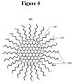
- Figure 4 illustrates a nanoparticle surrounded with surfactant molecules in accordance with one embodiment of the present invention
- Figure 5 illustrates a refractory metal nanoparticle mixture in accordance with one embodiment of the present invention
- Figure 6 is a flowchart illustrating a method for manufacturing refractory metal nanoparticles in accordance with one embodiment of the present invention
- Figure 7 is a flowchart illustrating a method for forming a refractory metal or refractory metal carbide coating in accordance with one embodiment of the present invention
- Figure 8 illustrates the formation of a refractory metal or refractory metal carbide coating in accordance with one embodiment of the present invention
- Figures 9A, 9B and 9C illustrate the formation of a refractory metal or refractory metal carbide coating in accordance with one embodiment of the present invention
- Figure 10 is a flow chart illustrating a method for forming a refractory metal carbide coating in accordance with one embodiment of the present invention
- Figure 11 is a flow chart illustrating a method for forming refractory metal or refractory metal carbide components in accordance with one embodiment of the present invention.
- Figure 12 is a flow chart illustrating a method for forming refractory metal carbide components in accordance with one embodiment of the present invention
- Figure 1 is a flowchart illustrating a method for manufacturing refractory metal or refractory metal nanoparticles in accordance with one embodiment of the present invention.
- the solvent may be a poly-ether solvent, such as, for example, a solvent characterized by the chemical formula R-O-(CH 2 CH 2 -O) x -R (where x is a positive integer, and R is a methyl group (CH 3 ), an ethyl group (C 2 H 5 ), a propyl group (C 3 H 7 ), or a butyl group (C 4 H 6 )).
- the solvent may be triglyme or tetrahydrofuran (THF).
- a refractory metal precursor including a refractory metal of interest is provided.
- the precursor may be a chloride of the desired refractory metal, such as TiCl 4 .
- a surfactant is provided.
- the surfactant may be an organic amine, phosphine, acid or the like.
- the surfactant may be n-hexylamine (CH 3 (CH 2 ) 5 NH 2 ), n-nonylamine (CH 3 (CH 2 ) 8 NH 2 ), n-dodecylamine (CH 3 (CH 2 ) 11 NH 2 ), or any other amine characterized by the chemical formula CH 3 (CH 2 ) x NH 2 , where x is a positive integer.
- a reactant capable of reducing the refractory metal in the precursor to its atomic form is provided.
- the reactant may be sodium naphthalene or lithium naphthalene, or any other reactant capable of reducing TaCl 5 .
- other reactants may be used.
- the precursor may be any one of any refractory metal halide, fluoride, chloride, bromide, iodide, alcoxide or refractory metal complex with acetylacetonate ligands
- the reactant may be any one of Li, K, Na, Mg, or Ca may be dissolved in THF and/or glyme in the presence of a promoter such as naphthalene (C 10 H 8 ), anthracene (C 14 H 10 ) or phenanthrene (C 14 H 10 ).
- step 105 the precursor, the reactant and the surfactant are combined in the poly-ether solvent to initiate a chemical reaction which forms nanoparticles of the refractory metal (e.g., titanium (Ti), zirconium (Zr), hafnium (Hf), niobium (Nb), tantalum (Ta), tungsten (W) or silicon (Si)), each of which is surrounded by a layer of molecules of the surfactant.
- the precursor is TiCl 4
- the reactant is sodium naphthalene
- the surfactant is n-hexylamine (CH 3 (CH 2 ) 5 NH 2 )
- the reaction proceeds as follows.
- the reactant and the refractory metal precursor react to free elemental Ti from the precursor.
- the sodium chloride (NaCl) precipitates out of the solution, while the free atoms of Ti metal rapidly coalesce to form Ti nanoparticles.
- the free electrons in the NH 2 end of the n-hexylamine (CH 3 (CH 2 ) 5 NH 2 ) surfactant molecules in the solvent are drawn to and form bonds with the dangling bonds (i.e., the unsaturated bonding orbitals) of the outermost Ti atoms in the rapidly growing Ti nanoparticles, such that the surfactant molecules form a protective barrier around the nanoparticles which prevents their further growth.
- the promoter (e.g., naphthalene, anthracene, phenanthrene, etc .) does not take part in the reaction directly and can be reclaimed and recycled by vacuum sublimation, as illustrated in the generalized exemplary equations set forth below: TiCl 4 + surfactant + 4 Na(promoter) ⁇ nano-Ti(surfactant) + 4 NaCl + 4 promoter ZrCl 4 + surfactant + 4 Na(promoter) ⁇ nano-Zr(surfactant) + 4 NaCl + 4 promoter HfCl 4 + surfactant + 4 Na(promoter) ⁇ nano-Hf(surfactant) + 4 NaCl + 4 promoter NbCl 5 + surfactant + 5 Na(promoter) ⁇ nano-Nb(surfactant) + 5 NaCl + 5 promoter TaCl 5 + surfact
- the reactant may be an alkali or alkaline earth metal dissolved in an ether, optionally including a promoter such as naphthalene (C 10 H 8 ), anthracene (C 14 H 10 ) or phenanthrene (C 14 H 10 ).
- the reactant may be a sodium naphthalene mixture formed according to the following method. First, 2g ofNa (87 mmol) cut into small pieces for faster reaction (commercially available Na sand can be used as well) are added to a dry reaction container filled with an inert gas atmosphere containing 12 g of naphthalene (93.6 mmol).
- the reaction container is heated while the mixture is stirred, and the temperature is monitored via a thermocouple.
- the temperature should increase from room temperature to 130 °C in about 20 minutes. Naphthalene starts subliming around 120 °C and sometimes some of it will melt during this procedure.
- the mixture is chilled ( e.g., with a dry ice/ DI water bath) to 0 C, and 100 ml dry THF is added to the mixture.
- the mixture will almost immediately turn a very dark forest green color, indicating the successful formation of the sodium naphthalene complex.
- the reaction is kept cold by adding dry ice and water to the cooling bath in order to prevent the sodium complex from decomposing back into elemental sodium.
- the sodium After 1-2 hours, the sodium will have dissolved, depending on the size of the Na pieces added and how well the procedure has been carried out. It is important to have absolutely dry reaction containers and chemicals, since the sodium is in an extremely reactive state and will react immediately with any moisture or oxygen or any other reactive chemical present.
- the reactant may be a lithium naphthalene mixture formed according to the following method.
- 0.7 g (101 mmol) of Li cut into small pieces for faster reaction are added to a dry reaction container filled with an inert gas atmosphere containing 12 g of naphthalene (93.6 mmol).
- the reaction container is heated while the mixture is stirred, and the temperature is monitored via a thermocouple.
- the temperature should increase from room temperature to 130 °C in about 20 minutes. Naphthalene starts subliming around 120 °C and sometimes some of it will melt during this procedure.
- the mixture is chilled ( e.g., with a dry ice/ DI water bath) to 0 C, and 100 ml dry THF is added to the mixture.
- the mixture will almost immediately turn a very dark forest green color, indicating the successful formation of the lithium naphthalene complex.
- the reaction is kept cold by adding dry ice and water to the cooling bath in order to prevent the lithium complex from decomposing back into elemental lithium. After 1-2 hours, the lithium will have dissolved, depending on the size of the Li pieces added and how well the procedure has been carried out. It is important to have absolutely dry reaction containers and chemicals, since the lithium is in an extremely reactive state and will react immediately with any moisture or oxygen or any other reactive chemical present.
- the reactant may be a potassium naphthalene mixture formed according to the following method.
- 3.4 g (87 mmol) ofK cut into small pieces for faster reaction are added to a dry reaction container filled with an inert gas atmosphere containing 12 g of naphthalene (93.6 mmol).
- the reaction container is heated while the mixture is stirred, and the temperature is monitored via a thermocouple.
- the temperature should increase from room temperature to 130 °C in about 20 minutes. Naphthalene starts subliming around 120 °C and sometimes some of it will melt during this procedure.
- the mixture is chilled ( e.g., with a dry ice/ DI water bath) to 0 C, and 100 ml dry THF is added to the mixture.
- the mixture will almost immediately turn a very dark forest green color, indicating the successful formation of the potassium naphthalene complex.
- the reaction is kept cold by adding dry ice and water to the cooling bath in order to prevent the potassium complex from decomposing back into elemental K. After 1-2 hours, the potassium will have dissolved, depending on the size of the K pieces added and how well the procedure has been carried out. It is important to have absolutely dry reaction containers and chemicals, since the potassium is in an extremely reactive state and will react immediately with any moisture or oxygen or any other reactive chemical present.
- the reactant may be a mixture of any one of lithium, potassium, sodium, magnesium or calcium, together with naphthalene, anthracene or phenanthrene.
- the order in which the reagents are combined is important for ensuring a narrow size distribution of refractory metal nanoparticles.
- the surfactant and the precursor are added to the solvent (and thoroughly distributed therein) before the reactant is added thereto, local differences in the concentration of the refractory metal precursor and the surfactant can be avoided. This equilibrium ensures that when the reactant is added, the refractory metal nanoparticles that form will form in a similar manner and achieve similar sizes.
- the speed with which the reactant is added to the reaction is important for ensuring a narrow size distribution of refractory metal nanoparticles, in accordance with one embodiment of the present invention.
- By slowly adding the reactant e.g., at a rate of about 50 to 60 drops per minute
- local differences in the concentration of the reactant can similarly be avoided, to ensure that the refractory metal nanoparticles form in near-equilibrium conditions and achieve similar final sizes.
- a larger particle size distribution can be achieved (e.g., due to the local concentration differences that occur).
- reactant can be slowly added until nearly all of the precursor has been consumed, at which time a surplus of reactant (i.e ., more than is needed to react with all of the refractory metal precursor) is quickly added to ensure that all the remaining precursor is reacted with.
- a surplus of reactant i.e ., more than is needed to react with all of the refractory metal precursor
- This approach offers the advantage of ensuring that nearly all of the nanoparticles will achieve a similar size, while also ensuring that all of the precursor is consumed.
- the surfactant used to prevent further nanoparticle growth is n-hexylamine
- the scope of the present invention is not limited to this arrangement. Rather, as will be apparent to one of skill in the art, any one of a number of polar surfactant molecules with free electrons or electron pairs may be used as a surfactant with refractory metal nanoparticles.
- only one surfactant was used, the present invention has application to reactions in which multiple surfactants are used to control the growth of nanoparticles.
- the surfactant(s) used may be any one or more surfactants chosen from the illustrative list in Table 1, below: Table 1 Surfactant Type Representative List Organic amine (mono-, di-and tri-) Pyridine Triethanol amine Diethylene triamine Ethylene diamine (C2 to C16) Hexyl-, nonyl-, Dodecyl amine (C6 to C16) Organic amine halide salt (mono-, di-, tri- and tetra-) Hexyl- nonyl-, Hexadecyl ammonium chloride (C6 to C16) Hexyl- nonyl-, Hexadecyl ammonium boride (C6 to C16) Organic alcohol Octanol, decanol, dodecanol (C6 to C16) Organic acid C2 to C16: Acetic acid, Hexanoic acid Oleic acid (cis-9-octadecenoic acid) Organic phosphine
- a mixture of an organic phosphine/phosphine oxide, an organic amine, and an organic amine halide salt may be used to provide improved particle size control for a particular reaction (as one surfactant may be preferentially coordinating to the metal precursor, while another surfactant may preferentially coordinate with the elemental metal, and yet a third surfactant may preferentially coordinate with the nanoparticle).
- some strong reducing agents e.g., Li, K, Na, Mg, Ca, etc.
- they should therefore not be used during the initial nanoparticle formation, but these can later be exchanged for, e.g., saturated amines.
- the length of the carbon chains and number thereof on the surfactant molecule play an important role in determining the amount of protection given the nanoparticle.
- chains shorter than C6 do not bond sufficiently with the nanoparticle to protect it, as little thermal energy is required to cause these molecules to come off.
- the surfactant material is increasingly difficult to remove, which will make forming refractory metal coatings increasingly difficult, as is described in greater detail below.
- amines bond more strongly to refractory metal nanoparticles than do alcohols, as the former exhibit higher Lewis Base strength, due to their ability to establish a higher covalent bond character.
- two or more refractory metal precursors may be reacted in a single reaction, to provide mixed metal systems and alloys.
- a metal precursor and a silicon precursor metal silicides may be formed.
- FIG. 2 is a flowchart illustrating a method for manufacturing refractory metal nanoparticles in accordance with another embodiment of the present invention.
- a poly-ether solvent such as monoglyme CH 3 -O-CH 2 CH 2 -O-CH 3 , diglyme CH 3 -O-(CH 2 CH 2 -O) 2 -CH 3 , triglyme CH 3 -O-(CH 2 CH 2 -O) 3 -CH 3 , or any other glyme characterized by the chemical formula R-O-(CH 2 CH 2 -O) x -R, where x is a positive integer and R is a methyl group (CH 3 ), an ethyl group (C 2 H 5 ), a propyl group (C 3 H 7 ), or a butyl group (C 4 H 6 ), is provided.
- step 202 a refractory metal precursor and a reactant are reacted in the poly-ether solvent to free refractory metal atoms from the precursor. The byproducts of this reaction are precipitated out of solution or boiled off.
- step 203 the refractory metal particles are combined in the poly-ether solvent to form a refractory metal nanoparticle.
- step 204 the refractory metal nanoparticle is surrounded, in the poly-ether solvent, with a layer of surfactant molecules.
- the surfactant molecules which are provided in the solvent at the beginning of the reaction, may be one or more of n-hexylamine (CH 3 (CH 2 ) 5 NH 2 ), n-nonylamine (CH 3 (CH 2 ) 8 NH 2 ), n-dodecylamine (CH 3 (CH 2 ) 11 NH 2 ), or any other amine or mixture of amines characterized by the chemical formula CH 3 (CH 2 ) x NH 2 , where x is a positive integer.
- Reactor system 300 includes a continuous stirred-tank reactor 301, into which reagents 306 are provided via a syringe or an addition funnel 302.
- An impeller 307 stirs the reagents 306 to ensure thorough mixing thereof (e.g., to optimize the particle size distribution of the refractory metal nanoparticles).
- a condenser 303 allows gases created in the chemical reactions occurring in reactor 301 (e.g., hydrogen in the present exemplary embodiment) to escape through outlet 305, while coolant which flows through ports 304 through condenser 303 cools more volatile species (such as the surfactant or the solvent) and allows them to trickle back down along the corkscrew-shaped path in condenser 303 into reactor 301.
- a thermometer 308 is used to track the temperature of the reagents 306 during the chemical reaction.
- System 300 may further include a heat source (not illustrated) to increase the temperature of the reaction, and thereby control the size and size distribution of the refractory metal nanoparticles, as described in greater detail below.
- reactor 301 can be heated (or cooled) to control the temperature at which the reactions therein take place.
- the duration for which heat is applied provides a mechanism for ensuring even distribution of the reagents during the reaction and thorough mixing thereof, so that the size distribution of the refractory metal nanoparticles can be narrowed.
- reactor 301 is heated for about 90 minutes after combining the solvent, refractory metal precursor and surfactant therein to ensure an even distribution thereof.
- the concentration of surfactant in the reaction can similarly modify the resultant size and size distribution of refractory metal nanoparticles.
- the refractory metal nanoparticles are more likely to encounter and bond with surfactant molecules early in their growth, resulting in both smaller nanoparticles, and a smaller distribution of particle sizes.
- the refractory metal nanoparticles have been described with respect to particular sizes, the scope of the present invention is not limited to these particular arrangements. For example, by reducing the concentration of surfactant in the reaction or increasing the speed with which the reactant is added thereto, refractory metal nanoparticles larger than 100 nm may be manufactured. Alternatively, by increasing the concentration of surfactant in the reaction, nanoparticles as small as 4 nm nay be manufactured. As will be apparent to one of skill in the art, the present invention has application to the manufacture of refractory metal nanoparticles of nearly any size.
- a mixture including 4.1 g (20 mmol) of TiCl 4 , 20 ml of either THF or triglyme and 80 mmol of dodecyl amine is provided.
- one of the above mixtures containing solubilized alkaline or alkaline earth metal with a four-fold excess is slowly added via an addition funnel, to produce four equivalents of NaCl and titanium nanoparticles, which appear as black powder.
- the Ti particle size is controlled by both the amount of the amine surfactant in the mixture and the temperature at which the reaction with the reagent is carried out. With these particular reagents, the reaction commences very rapidly and can be carried out at room temperature (e.g., about 20 °C).
- a mixture including 5.75 g (14.5 mmol) of WCl 6 , 50 ml of either THF or triglyme and 80 mmol of dodecyl amine is provided.
- one of the above mixtures containing solubilized alkaline or alkaline earth metal with a four-fold excess is slowly added via an addition funnel, to produce four equivalents of NaCl and tungsten nanoparticles (black powder).
- the W particle size is controlled by both the amount of the amine surfactant in the mixture and the temperature at which the reaction with the reagent is carried out. With these particular reagents, the reaction commences very rapidly and can be carried out at room temperature (e.g., about 20 °C).
- a mixture including 4.1 g (20 mmol) of SiCl 4 , with 20 ml of either THF or triglyme and 80 mmol of dodecyl amine is provided.
- one of the above mixtures containing solubilized alkaline or alkaline earth metal with a four-fold excess is slowly added via addition funnel, to produce four equivalents of NaCl and silicon nanoparticles (black powder).
- the Si particle size is controlled by both the amount of the amine surfactant in the mixture and the temperature at which the reaction with the reagent is carried out. With these particular reagents, the reaction commences very rapidly and can be carried out at room temperature (e.g., about 20 °C).
- FIG. 4 illustrates a single refractory metal nanoparticle in greater detail, in accordance with one embodiment of the present invention.
- Refractory metal nanoparticle 400 includes a plurality of refractory metal atoms 401 tightly bonded together.
- Surrounding atoms 401 is a layer of surfactant molecules 402, in this case, n-hexylamine (CH 3 (CH 2 ) 5 NH 2 ).
- n-hexylamine CH 3 (CH 2 ) 5 NH 2
- the NH 2 end of each n-hexylamine molecule has bonded with the dangling bonds (i.e ., the unsaturated bonding orbitals) of the outermost refractory metal atoms 401 in refractory metal nanoparticle 400 to form a protective barrier around nanoparticle 400.
- Figure 4 illustrates a single particle in cross-section, showing only a ring of surfactant molecules at the periphery of the nanoparticle
- an actual nanoparticle has a three-dimensional shell of surfactant molecules 402 surrounding the refractory metal atoms 401 on all sides.
- surfactant molecules 402 need not be the same surfactant molecules used to stop refractory metal nanoparticle 400 from growing during the manufacture thereof. Rather, as will be immediately understood by one of skill in the art, a simple ligand exchange may be used to replace some or all of the surfactant molecules which were used in the manufacture of refractory metal nanoparticle 400.
- Nanoparticle mixture 500 includes a solvent 501, in which are disposed a plurality of refractory metal nanoparticles 502.
- the solvent 501 need not be the same poly-ether solvent used in the manufacturing process of refractory metal nanoparticles 502. Rather, different solvents may be used in nanoparticle mixture 500 depending upon whether nanoparticle mixture 500 is to be used to coat a surface, as described in greater detail below, or whether nanoparticle mixture 500 is being stored.
- solvent 501 is hexane CH 3 (CH 2 ) 4 CH 3 , a solvent with a low boiling point ( ⁇ 69 °C), suitable for use in the refractory metal nanoparticle coating processes described in greater detail below.
- Each nanoparticle 502 is surrounded by a layer of surfactant molecules which form a protective barrier around the nanoparticle, preventing it from chemically reacting with other substances, such as air or moisture.
- This protective layer of surfactants around each nanoparticle 502 allows mixture 500 to be handled with relative safety (e.g., as the pyrophoricity of the nanoparticles may be negated thereby).
- nanoparticles 502 may either be dissolved in solvent 501, or may alternately form a slurry therewith.
- solvent 501 for example, in hexane, nanoparticles smaller than 10 nm will dissolve, while those larger than about 10 nm will not.
- solvents such as xylene or toluene, larger nanoparticles will still be soluble.
- some nanoparticles may be dissolved in the solvent, while others form a slurry therewith.
- nanoparticles larger than 10 nm i.e., those that do not dissolve in hexane
- nanoparticles smaller than 10 nm i.e., those that do dissolve in hexane.
- These larger particles can then be introduced into a different solvent, such as xylene or toluene, to again separate smaller and larger particles (depending upon their solubility in this solvent).
- a third fraction of the nanoparticles can similarly be separated out by size in yet another solvent such as isopropyl alcohol ("IPA"). Nanoparticles (and agglomerates thereof) which are larger than about 100 nm will not dissolve well in any known organic solvent with low polarity.
- IPA isopropyl alcohol
- refractory metal nanoparticle mixture 500 may include refractory metal nanoparticles 502 of a variety of sizes and of different compositions.
- nanoparticles 502 may have a single, continuous particle size distribution, as a result of all the nanoparticles being created in a single reaction.
- nanoparticles 502 may have multiple non-continuous particle size distributions (e.g., as a result of mixing nanoparticles produced in separate reactions, or of separate compositions), where some of the nanoparticles are smaller (e.g. between 4 nm and 10 nm), and the remainder of the particles are larger (e.g., between 25 nm and 100 nm).
- This arrangement may be particularly desirable for increasing the volumetric packing efficiency of nanoparticles in a refractory metal coating, as discussed in greater detail below. It will be immediately apparent to one of skill in the art that the foregoing embodiments are merely exemplary, and that the present invention has application to refractory metal nanoparticle mixtures with any size refractory metal nanoparticles of any composition and with any particle size distribution.
- FIG. 6 is a flow chart illustrating an exemplary method by which refractory metal carbide nanoparticles may be manufactured in accordance with one embodiment of the present invention.
- the method begins with step 601, in which a refractory metal halide is provided.
- the refractory metal halide is treated with a reagent to provide a refractory metal alkyl precursor, such as, for example, Ti(CH 3 ) 4 .
- the reagent may be a Grignard reagent (e.g., an alkyl- or aryl-magnesium halides) or a lithium organic reagent.
- Some exemplary equations representing the treatment of step 602 are set forth below, for the provision of titanium, zirconium, and tungsten alkyl precursors: TiCl 4 + 4 LiCH 3 ⁇ Ti(CH 3 ) 4 + 4 LiCl (preferably conducted below -40 °C) ZrCl 4 + 4 LiCH 3 ⁇ Zr(CH 3 ) 4 + 4 LiCl (preferably conducted below -15 °C) WCl 6 + 6 LiCH 3 ⁇ W(CH 3 ) 6 + 6 LiCl (m.p. 30 °C)
- the refractory metal alkyl precursor thus formed includes the refractory metal and one or more alkyl groups.
- the refractory metal alkyl is heated in the presence of a surfactant, in order to decompose the refractory metal alkyl precursor into a refractory metal carbide nanoparticle surrounded by a layer of molecules of the surfactant.
- An exemplary equation representing the heating of a titanium alkyl precursor is set forth below: Ti(CH 3 ) 4 + heat ⁇ TiC + 3 CH 4
- the "heat” in the above equation may be more than about -40 °C. This low temperature allows for good particle size control, due to the reduced kinetic activity at that temperature.
- metalorganic compounds that allow for ⁇ -elimination may not be desirable, as these can lead to the formation of metal hydrides and pure metals, rather than the desired carbide, and/or may provide undesired sub-stoichiometric carbon content.
- Ti(C 2 H 5 ) 4 may not be a desirable precursor, as this precursor would be impracticably difficult to decompose into a carbide, due to the ⁇ -elimination mechanism and its low stability (e.g., requiring temperatures below -80 °C): Ti(C 2 H 5 ) 4 + heat ⁇ Ti + 4 C 2 H 4 +2 H 2
- the decomposition may not proceed as cleanly as desired, resulting in only a refractory metal carbide, but rather may produce a nonstoichiometric product mixture, thereby preventing the desired control.
- This is dependent upon the refractory metal alky precursor chosen, as will be readily apparent to those of skill in the art.
- Al(C 3 H 7 ) 3 may be used effectively for aluminum chemical vapor deposition for microelectronics applications.
- the heating of a refractory metal alkyl precursor should occur in the presence of a surfactant in order to halt the growth of the refractory metal carbide nanoparticles at a desired size or size range.
- a surfactant Similar surfactants and/or surfactant mixtures to those described above (e.g., in Table 1) may be used, in accordance with various aspects of the present invention.
- the forming metal nanoparticles can be "capped" with various organic groups (e.g., one or more methyls, ethyls, butyls, etc.) by using an otherwise insufficient amount of reducing agent, thereby leaving reactive halide groups on the nanoparticles' surfaces.
- the reagents used may include a Grignard reagent (e.g., an alkyl- or aryl-magnesium halide) or a lithium organic reagent. Both are readily available or easily prepared for a wide variety of alkyl groups, and have the additional advantage that Li and Mg are highly electropositve and thus usually cause the equilibrium of the reaction to lie to the right.
- lithium organic reagent such as LiCH 3
- the resultant lithium chloride precipitates and helps to force the reaction to the right.
- lithium organic reagents are readily available for many compounds and are easily synthesized form an organic halide (e.g. ICH 3 ) and lithium metal.
- these capped nanoparticles can be thermally decomposed directly into nanostructured carbide coatings or solid parts via moderate heating.
- Some exemplary equations representing the treatment are set forth below: nano Hf 2000 (CH 3 ) 100 (surf) + heat ⁇ nano HfC + H 2 + volatiles nano Ta 2000 (CH 3 ) 100 (surf) + heat ⁇ nano TaC + H 2 + volatiles nano W 2000 (CH 3 ) 100 (surf) + heat ⁇ nano WC + H 2 + volatiles
- the concentration of surfactant in the reaction can modify the resultant size and size distribution of refractory metal carbide nanoparticles.
- the refractory metal carbide nanoparticles are more likely to encounter and bond with surfactant molecules early in their growth, resulting in both smaller nanoparticles, and a smaller distribution of particle sizes.
- a refractory metal carbide nanoparticle may be surrounded by surfactant molecules different from those used to stop the refractory metal carbide nanoparticle from growing during the manufacture thereof, via a simple ligand exchange.
- a refractory metal carbide nanoparticle mixture may be provided, in which a plurality of refractory metal carbide nanoparticles are disposed in a solvent.
- Different solvents may be used in the nanoparticle mixture, depending upon whether nanoparticle mixture is to be used to coat a surface, as described in greater detail below, or whether the nanoparticle mixture is being stored.
- a solvent with a low boiling point such as hexane ( ⁇ 69 °C) may be used in the refractory metal carbide nanoparticle coating processes described in greater detail below.
- the nanoparticles may either be dissolved in a solvent, or may alternately form a slurry therewith.
- a solvent such as xylene or toluene
- nanoparticles smaller than 10 nm will dissolve, while those larger than about 10 nm will not.
- solvents such as xylene or toluene
- larger nanoparticles will still be soluble.
- some nanoparticles may be dissolved in the solvent, while others form a slurry therewith.
- nanoparticles larger than 10 nm i.e., those that do not dissolve in hexane
- nanoparticles smaller than 10 nm i.e., those that do dissolve in hexane.
- These larger particles can then be introduced into a different solvent, such as xylene or toluene, to again separate smaller and larger particles (depending upon their solubility in this solvent).
- a third fraction of the nanoparticles can similarly be separated out by size in yet another solvent such as isopropyl alcohol ("IPA"). Nanoparticles (and agglomerates thereof) which are larger than about 100 nm will not dissolve well in any known organic solvent with low polarity.
- IPA isopropyl alcohol
- a refractory metal carbide nanoparticle mixture may include refractory metal carbide nanoparticles of a variety of sizes and of different compositions. Moreover, a mixture may include both refractory metal nanoparticles and refractory metal carbide nanoparticles.
- the nanoparticles may have a single, continuous particle size distribution, as a result of all the nanoparticles being created in a single reaction. Alternatively, the nanoparticles may have multiple non-continuous particle size distributions ( e.g., as a result of mixing nanoparticles produced in separate reactions, or of separate compositions), where some of the nanoparticles are smaller ( e.g.
- a refractory metal or refractory metal carbide nanoparticle mixture can be "painted” onto surfaces to form thin coatings of refractory metals or refractory metal carbides. This is accomplished by disposing a refractory metal or a refractory metal carbide nanoparticle mixture onto a surface to be coated, and heating the "painted" mixture with progressively higher temperatures to (1) boil off the solvent, (2) boil off the surfactant and (3) "fuse" adjacent nanoparticles together. This process is described in greater detail below, with respect to Figure 7 .
- FIG. 7 is a flowchart illustrating a method for forming a refractory metal or refractory metal carbide coating in accordance with one embodiment of the present invention.
- the method begins with step 701, in which a refractory metal or refractory metal carbide nanoparticle mixture is provided.
- the nanoparticle mixture includes a solvent and a plurality of refractory metal or refractory metal carbide nanoparticles, each surrounded by a layer of surfactant molecules.
- the nanoparticle mixture is disposed on a surface to be coated.
- the coating process does not require the surface to be coated to withstand the very high temperatures associated with most metallurgical approaches to coating a surface with refractory metals or their carbides (although many coated surfaces will have application in high-temperature environments, and accordingly may be capable of withstanding such temperatures).
- the surface to be coated may be a carbon-based material, such as graphite or a carbon/carbon ("C/C") composite, which can withstand the low temperature coating process (e.g., which may occur at less than 20% of the bulk melting point of a carbide or refractory material used to coat it).
- the coated surface is heated to a first temperature to evaporate the solvent from the nanoparticle mixture, leaving the coated refractory metal or refractory metal carbide nanoparticles arranged in a lattice on the surface.
- the first temperature is chosen to be a temperature sufficiently high to evaporate the solvent, but not high enough to evaporate the surfactant layer around in each molecule.
- the first temperature may be between 125 °C and 175 °C.
- the first heating step 703 is illustrated in greater detail in accordance with one embodiment of the present invention.
- the nanoparticle mixture 801 which has been disposed on surface 802, is beginning to evaporate, leaving refractory metal or refractory metal carbide nanoparticles 803 arranged on surface 802.
- step 704 in which the coated surface is heated to a second temperature to remove the surfactant layers from around the nanoparticles.
- the second temperature is between about 130 °C and 150 °C. In removing the surfactant molecules, this second heating step effects a volumetric contraction of the lattice of refractory metal or refractory metal carbide nanoparticles.
- the volume of the coated refractory metal or refractory metal carbide nanoparticles may be significantly larger than the uncoated nanoparticles left after second heating step 704.
- the (single) surfactant used is hexylamine
- the volume of the nanoparticles contracts by about 17% after the second heating step. Accordingly, in choosing a surfactant (or combination of surfactants) to use in preparing a nanoparticle mixture, those which provide a lesser volumetric contraction during this step may be desirable to reduce cracking of the resultant coating, in accordance with one aspect of the present invention. This contraction is illustrated in greater detail in Figures 9A and 9B , in accordance with one embodiment of the present invention.
- Figure 9A illustrates an orderly lattice of surfactant-covered refractory metal or refractory metal carbide nanoparticles 901 disposed on a surface 902.
- the surfactant molecules 903 space the cores of the nanoparticles a significant distance apart. Once these particles are heated to the second temperature of step 704, the surfactant molecules 903 are removed, and nanoparticles 901 contract in their absence, as illustrated in Figure 9B . Depending upon the surfactant or surfactants used, this contraction may be significant enough to form cracks in the coating on surface 902.
- the removal of longer surfactant molecules may cause the refractory metal or refractory metal carbide nanoparticles to contract to such an extent, that the refractory metal or refractory metal carbide coating spalls and flakes off of surface 902.
- Figures 9A and 9B illustrate an embodiment of the present invention in which nanoparticles 901 are all approximately the same size (i.e., they have a very narrow particle size distribution), the scope of the present invention is not limited to such an arrangement. Rather, the present invention has application to nanoparticle coatings in which nanoparticles of different sizes and/or compositions are used to improve the packing efficiency thereof.
- nanoparticles of two approximate sizes may be provided in a nanoparticle mixture, where the smaller nanoparticles are approximately 10% of the volume of the larger particles, to provide greater spherical packing efficiency (wherein the smaller particles occupy the interstitial spaces between the larger particles in the lattice).
- the smaller nanoparticles may have the same composition as the larger particles, or they may be a different composition (e.g., including a different refractory metal or refractory metal carbide). Other arrangements with different particle size distributions may also be provided, to further improve packing efficiency and crack resilience, within the scope of the present invention.
- steps 703 and 704 may occur in any order, or may be combined in to a single step, in which the first and second temperature are one and the same.
- step 705 in which the coated surface is heated to a third temperature to bond the nanoparticles together to form a coating on the surface.
- the third temperature is between about 550 °C and 1000 °C (depending upon the melting point of the specific material). This temperature "fuses" or bonds the adjacent nanoparticles to each other, to form a coherent coating of the refractory metal or refractory metal carbide on the substrate. This bonding is illustrated in Figure 9C , in which nanoparticles 901 have bonded as a result of the application of the third temperature.
- an important advantage of the present invention is the ability to form refractory metal or refractory metal carbide coatings on materials not previously capable of being so coated.
- the foregoing method can be used to coat carbon-based materials (e.g., graphite, carbon/carbon composites) and other temperature sensitive materials (e.g., materials that would melt, oxidize, or otherwise not withstand temperatures above 800 °C).
- carbon-based materials e.g., graphite, carbon/carbon composites
- other temperature sensitive materials e.g., materials that would melt, oxidize, or otherwise not withstand temperatures above 800 °C.
- the present invention has application to coating a wide range of materials that might enjoy the benefits of a refractory metal or refractory metal carbide coating.
- a refractory metal or refractory metal carbide nanoparticle mixture allows shapes not previously capable of being coated with refractory metal or refractory metal carbides to be coated using the foregoing methods, in accordance with yet other embodiments of the present invention.
- internal surfaces of complex shapes e.g., the inner diameter of tubes or nozzles
- high-aspect ratio surfaces can be coated with a refractory metal or refractory metal carbide nanoparticle coating, in accordance with various embodiments of the present invention.
- a refractory metal coating may be formed from refractory metal nanoparticles (as opposed to refractory metal carbide nanoparticles).
- a refractory metal nanoparticle mixture including refractory metal nanoparticles in a solvent is provided on a surface to be coated.
- the refractory metal nanoparticle mixture includes a non-volatile surfactant, which may be provided in layers around the refractory metal nanoparticles by ligand exchange (e.g., exchanging the non-volatile surfactant for the surfactant which originally halted the growth of the nanoparticle, as set forth in greater detail above), or which may be provided in a mixture with the refractory metal nanoparticles ( i.e ., in addition to the surfactant which surrounds the nanoparticles).
- ligand exchange e.g., exchanging the non-volatile surfactant for the surfactant which originally halted the growth of the nanoparticle, as set forth in greater detail above
- ligand exchange e.g., exchanging the non-volatile surfactant for the surfactant which originally halted the growth of the nanoparticle, as set forth in greater detail above
- ligand exchange e.g., exchanging the non-volatile surfactant for the surfact
- Appropriate surfactants include, for example, long chain organics (e.g., with more than 10 carbon atoms and a functional group at one or both ends), such as amines, acids, phosphines, acetylactonates, thioethers or thiols. Shorter surfactants may be used as well, when another carbon source is dispersed with the metal nanoparticles. That carbon source may be, for example, long chain hydrocarbon (e.g., paraffin wax). Using a secondary hydrocarbon source helps to create a reducing atmosphere that prevents oxidation and/or the incorporation of oxygen into the coating.
- long chain organics e.g., with more than 10 carbon atoms and a functional group at one or both ends
- Shorter surfactants may be used as well, when another carbon source is dispersed with the metal nanoparticles.
- That carbon source may be, for example, long chain hydrocarbon (e.g., paraffin wax).
- step 1002 the refractory metal nanoparticle mixture is heated to a first temperature to evaporate the solvent and leave the plurality of refractory metal nanoparticles surrounded by surfactant molecules on the surface.
- step 1003 the refractory metal nanoparticles and the surfactant molecules are heated to a second temperature to decompose the surfactant molecules, and to react the plurality of refractory metal nanoparticles with carbon from the decomposed surfactant to provide a refractory metal carbide coating on the surface. Due to the high reactivity of the nano-particles, this process can take place at very low temperatures ( i.e., much lower than standard carbide processes). A generalized equation illustrating this process is set forth below, where "Nano-M" represents a nanoparticle of refractory metal: Nano-M(surfactant) + heat ⁇ Nano-MC + H 2 + volatiles
- the nanoparticle of interest may be titanium. Accordingly, a decomposition reaction for this nanoparticle may occur as set forth in the following equation: Nano-Ti 18 (octadecylamine) + heat ⁇ (Nano-TiC) 18 + 18 H 2 + NH 3
- the foregoing method may be practiced with the surface to be coated and the nanoparticle mixture disposed in a chamber filled with inert gas, in order to prevent the surfactant from escaping from the nanoparticle mixture. This may be done when the surfactant which surrounds the nanoparticles functions as the carbon source for the reaction. According to yet another embodiment, however, if another non-volatile carbon source is added, the reaction may occur under atmospheric conditions.
- the decomposition reaction may occur as set forth in the following equation: Nano-Ti 18 + octadecane + heat ⁇ (nano-TiC) 18 + 18 H 2
- the surfactants in the above reaction may include one or more amines such as aliphatic amines, n-butyl amines, pentyl, hexyl, octyl, etc. with one, two or three aliphatic chains attached.
- the foregoing exemplary organic compounds are known to bond well to most transition metal centers and have been shown to stabilize different nanoparticles as well.
- the early electropositive transition metals such as Zr, Hf, Nb, Ta bond more strongly to oxide functional groups than amines or phosphines. Therefore, phosphine oxides and organic acids are the preferred ligands for these metals as well as long chain alcohols such as octanol, dodecanol, etc.
- Ti, W and Si exhibit a relative high affinity to nitrogen ( e.g., Ti bums in nitrogen atmosphere to TiN) and therefore amines may be a good choice for these metals.
- refractory metal or refractory metal carbide nanoparticle mixtures may be used to form fully dense components via sintering or hot pressing.
- Figure 11 is a flow chart illustrating a method for forming refractory metal or refractory metal carbide components in accordance with one embodiment of the present invention.
- the method begins with step 1101, in which a refractory metal or refractory metal carbide nanoparticle mixture is provided in a mold.
- the mixture includes a solvent and a plurality of refractory metal (or carbide) nanoparticles, each of the nanoparticles being surrounded by a layer of surfactant molecules.
- the refractory metal nanoparticle mixture is sintered to consolidate the refractory metal component in the shape of the mold.
- the sintering may alternately comprise spark plasma sintering (SPS) or field assisted sintering (FAST).
- FAST uses direct resistive heating with a high current (e.g., hundreds of amps, depending on the electrical resistivity of the substrate) and a low voltage (e.g., less than 25 V) to rapidly heat the mixture in the mold, with very moderate pressure applied. This technique is very fast, taking mere minutes, but can nevertheless provide fully dense parts.
- a refractory metal carbide component can be manufactured from refractory metal nanoparticles (as opposed to refractory metal carbide nanoparticles).
- One such exemplary method is set forth in Figure 12 . The method begins with step 1201, in which a refractory metal nanoparticle mixture is disposed in a mold.
- the refractory metal nanoparticle mixture includes a non-volatile surfactant, which may be provided in layers around the refractory metal nanoparticles by ligand exchange (e.g., exchanging the non-volatile surfactant for the surfactant which originally halted the growth of the nanoparticle, as set forth in greater detail above), or which may be provided in a mixture with the refractory metal nanoparticles ( i.e ., in addition to the surfactant which surrounds the nanoparticles).
- ligand exchange e.g., exchanging the non-volatile surfactant for the surfactant which originally halted the growth of the nanoparticle, as set forth in greater detail above
- ligand exchange e.g., exchanging the non-volatile surfactant for the surfactant which originally halted the growth of the nanoparticle, as set forth in greater detail above
- ligand exchange e.g., exchanging the non-volatile surfactant for the surfact
- Appropriate surfactants include, for example, long chain organics (e.g., with more than 10 carbon atoms and a functional group at one or both ends), such as amines, acids, phosphines, acetylactonates, thioethers or thiols. Shorter surfactants may be used as well, when another carbon source is dispersed with the metal nanoparticles. That carbon source may be, for example, long chain hydrocarbon (e.g., paraffin wax). Using a secondary hydrocarbon source helps to create a reducing atmosphere that prevents oxidation and/or the incorporation of oxygen into the component.
- long chain organics e.g., with more than 10 carbon atoms and a functional group at one or both ends
- Shorter surfactants may be used as well, when another carbon source is dispersed with the metal nanoparticles.
- That carbon source may be, for example, long chain hydrocarbon (e.g., paraffin wax).
- step 1202 the refractory metal nanoparticle mixture is heated to a first temperature to evaporate the solvent and leave the plurality of refractory metal nanoparticles surrounded by surfactant molecules in the mold.
- step 1203 the refractory metal nanoparticles and the surfactant molecules are heated to a second temperature to decompose the surfactant molecules and to react the plurality of refractory metal nanoparticles with carbon from the decomposed surfactant to provide a refractory metal carbide component.
- Nano-M represents a nanoparticle of refractory metal: Nano-M(surfactant) + heat ⁇ Nano-MC + H 2 + volatiles
- the nanoparticle of interest may be titanium. Accordingly, a decomposition reaction for this nanoparticle may occur as set forth in the following equation: Nano-Ti 18 (octadecylamine) + heat ⁇ (Nano-TiC) 18 + 18 H 2 + NH 3
- the foregoing method may be practiced with the nanoparticle mixture and the mold disposed in a chamber filled with inert gas, in order to prevent the surfactant from escaping from the nanoparticle mixture. This may be done when the surfactant which surrounds the nanoparticles functions as the carbon source for the reaction. According to yet another embodiment, however, if another non-volatile carbon source is added, the reaction may occur under atmospheric conditions.
- the decomposition reaction may occur as set forth in the following equation: Nano-Ti 18 + octadecane + heat ⁇ (nano-TiC) 18 + 18 H 2
- the surfactants in the above reaction may include one or more amines such as aliphatic amines, n-butyl amines, pentyl, hexyl, octyl, etc. with one, two or three aliphatic chains attached.
- the foregoing exemplary organic compounds are known to bond well to most transition metal centers and have been shown to stabilize different nanoparticles as well.
- the early electropositive transition metals such as Zr, Hf, Nb, Ta bond more strongly to oxide functional groups than amines or phosphines. Therefore, phosphine oxides and organic acids are the preferred ligands for these metals as well as long chain alcohols such as octanol, dodecanol, etc.
- Ti, W and Si exhibit a relative high affinity to nitrogen ( e.g., Ti bums in nitrogen atmosphere to TiN) and therefore amines may be a good choice for these metals.
- refractory metal carbide coatings and components enjoy enhanced deformation characteristics similar to those of metals.
- nanostructured carbide components and coatings formed according to one of the exemplary methods of the present invention exhibit deformation before failure. This is advantageous, since many ceramics are brittle below their ductile-to-brittle transition temperature. This low temperature brittleness often leads to low temperature failure.
- a nano-grained structure coupled with a stable grain size allows the material to deform along its grain boundaries, as the nanoparticles therein exhibit a large number of unsaturated or "dangling" bonds that form a very strong connection to their neighboring particles. During deformation, some bonds may be broken, but there are many others that do not break, keeping the coating or bulk part solid. This process is similar to that which occurs in the deformation of metals.
- the method comprises the steps of:
- the refractory metal can be chosen from the group consisting of titanium (Ti), zirconium (Zr), hafnium (Hf), niobium (Nb), tantalum (Ta), tungsten (W), and silicon (Si).
- the refractory metal precursor can be selected from the group consisting of halides, fluorides, chlorides, bromides, iodides, alcoxides and metal complexes with acetylacetonate ligands.
- the reactant may comprise a metal dissolved in an ether, wherein the metal is selected from the group consisting of lithium (Li), potassium (K), sodium (Na), magnesium (Mg), and calcium (Ca).
- the reactant further comprises a promoter selected from the group consisting of naphthalene (C 10 H 8 ), anthracene (C 14 H 10 ) and phenanthrene (C 14 H 10 ).
- a promoter selected from the group consisting of naphthalene (C 10 H 8 ), anthracene (C 14 H 10 ) and phenanthrene (C 14 H 10 ).
- the ether is selected from the group consisting oftetrahydrofuran ((CH 2 ) 4 O), diethyl ether CH 3 -CH 2 -O-CH 2 -CH 3 and glyme.
- the solvent can be a poly-ether solvent characterized by the chemical formula R-O-(CH 2 CH 2 -O) x -R, where x is a positive integer, and where R is a methyl group (CH 3 ), an ethyl group (C 2 H 5 ), a propyl group (C 3 H 7 ), or a butyl group (C 4 H 6 ).
- the surfactant may be an amine characterized by the chemical formula CH 3 (CH 2 ) x NH 2 , where x is a positive integer.
- the surfactant may be selected from the group consisting of n-hexylamine (CH 3 (CH 2 ) 5 NH 2 ), n-nonylamine (CH 3 (CH 2 ) 8 NH 2 ) and n-dodecylamine (CH 3 (CH 2 ) 11 NH 2 ).
- the surfactant may be oleic acid.
- the combining step may include controlling a temperature of the solvent to control an average size of the plurality of refractory metal nanoparticles.
- the above method preferably further comprises the step of providing a second surfactant, and the combining step preferably further includes combining the second surfactant with the refractory metal precursor, the reactant and the surfactant in the solvent.
- the method comprises the steps of:
- the refractory metal coating may comprise a refractory metal chosen from the group consisting of titanium (Ti), zirconium (Zr), hafnium (Hf), niobium (Nb), tantalum (Ta), tungsten (W), silicon (Si), and combinations thereof.
- the solvent may be a poly-ether solvent characterized by the chemical formula R-O-(CH 2 CH 2 -O) x -R, where x is a positive integer, and where R is a methyl group (CH 3 ), an ethyl group (C 2 H 5 ), a propyl group (C 3 H 7 ), or a butyl group (C 4 H 6 ).
- the surfactant may be an amine characterized by the chemical formula CH 3 (CH 2 ) x NH 2 , where x is a positive integer.
- the surfactant may be selected from the group consisting of n-hexylamine (CH 3 (CH 2 ) 5 NH 2 ), n-nonylamine (CH 3 (CH 2 ) 8 NH 2 ) and n-dodecylamine (CH 3 (CH 2 ) 11 NH 2 ).
- the surfactant may be oleic acid.
- the surface to be coated may be disposed in a high-aspect ratio structure.
- the heating to the first, second or third temperatures may comprise resistively heating the surface to be coated.
- the method comprises the steps of:
- the sintering step may comprise spark plasma sintering.
- the sintering step may comprise field assisted sintering.
- a fourth reference method for forming a refractory metal carbide component comprises the steps of:
- the sintering step may comprise spark plasma sintering.
- the sintering step may comprise field assisted sintering.
- a fifth method for forming a refractory metal carbide component comprises the steps of:
- the refractory metal carbide component may comprise a carbide of a refractory metal chosen from the group consisting of titanium (Ti), zirconium (Zr), hafnium (Hf), niobium (Nb), tantalum (Ta), tungsten (W), and silicon (Si).
- the solvent may be a poly-ether solvent characterized by the chemical formula R-O-(CH 2 CH 2 -O) x -R, where x is a positive integer, and where R is a methyl group (CH 3 ), an ethyl group (C 2 H 5 ), a propyl group (C 3 H 7 ), or a butyl group (C 4 H 6 ).
- the surfactant may comprise a hydrocarbon.
- the heating to the second temperature may occur in an inert gas chamber.
Applications Claiming Priority (4)
| Application Number | Priority Date | Filing Date | Title |
|---|---|---|---|
| US1709807P | 2007-12-27 | 2007-12-27 | |
| US19197508A | 2008-08-14 | 2008-08-14 | |
| EP08867229.0A EP2225101B1 (fr) | 2007-12-27 | 2008-09-02 | Métaux réfractaires nanostructurés, carbures de métal et revêtements et pièces fabriqués à partir de ceux-ci |
| PCT/US2008/075049 WO2009085342A1 (fr) | 2007-12-27 | 2008-09-02 | Métaux réfractaires nanostructurés, carbures de métal et revêtements et pièces fabriqués à partir de ceux-ci |
Related Parent Applications (2)
| Application Number | Title | Priority Date | Filing Date |
|---|---|---|---|
| EP08867229.0A Division-Into EP2225101B1 (fr) | 2007-12-27 | 2008-09-02 | Métaux réfractaires nanostructurés, carbures de métal et revêtements et pièces fabriqués à partir de ceux-ci |
| EP08867229.0A Division EP2225101B1 (fr) | 2007-12-27 | 2008-09-02 | Métaux réfractaires nanostructurés, carbures de métal et revêtements et pièces fabriqués à partir de ceux-ci |
Publications (3)
| Publication Number | Publication Date |
|---|---|
| EP2687365A2 true EP2687365A2 (fr) | 2014-01-22 |
| EP2687365A3 EP2687365A3 (fr) | 2014-08-13 |
| EP2687365B1 EP2687365B1 (fr) | 2019-02-20 |
Family
ID=40824620
Family Applications (2)
| Application Number | Title | Priority Date | Filing Date |
|---|---|---|---|
| EP13188147.6A Active EP2687365B1 (fr) | 2007-12-27 | 2008-09-02 | Procédés de fabrication des carbures de métaux réfractaires |
| EP08867229.0A Active EP2225101B1 (fr) | 2007-12-27 | 2008-09-02 | Métaux réfractaires nanostructurés, carbures de métal et revêtements et pièces fabriqués à partir de ceux-ci |
Family Applications After (1)
| Application Number | Title | Priority Date | Filing Date |
|---|---|---|---|
| EP08867229.0A Active EP2225101B1 (fr) | 2007-12-27 | 2008-09-02 | Métaux réfractaires nanostructurés, carbures de métal et revêtements et pièces fabriqués à partir de ceux-ci |
Country Status (3)
| Country | Link |
|---|---|
| US (2) | US8753720B2 (fr) |
| EP (2) | EP2687365B1 (fr) |
| WO (1) | WO2009085342A1 (fr) |
Cited By (1)
| Publication number | Priority date | Publication date | Assignee | Title |
|---|---|---|---|---|
| CN105239031A (zh) * | 2015-09-28 | 2016-01-13 | 华为杰通(北京)科技有限公司 | 金属量子雾化生长装置 |
Families Citing this family (10)
| Publication number | Priority date | Publication date | Assignee | Title |
|---|---|---|---|---|
| US7736414B1 (en) | 2006-05-17 | 2010-06-15 | Lockheed Martin Corporation | Rhenium nanoparticles |
| US20100075137A1 (en) * | 2006-05-17 | 2010-03-25 | Lockheed Martin Corporation | Carbon nanotube synthesis using refractory metal nanoparticles and manufacture of refractory metal nanoparticles |
| US9120245B1 (en) | 2007-05-09 | 2015-09-01 | The United States Of America As Represented By The Secretary Of The Air Force | Methods for fabrication of parts from bulk low-cost interface-defined nanolaminated materials |
| DE102011010899A1 (de) * | 2011-02-04 | 2012-08-09 | Fraunhofer-Gesellschaft zur Förderung der angewandten Forschung e.V. | Verfahren zum Erzeugen einer dreidimensionalen Struktur sowie dreidimensionale Struktur |
| EP2812139B1 (fr) | 2012-02-10 | 2017-12-27 | Lockheed Martin Corporation | Formulations de pâte de nanoparticules et leurs procédés de production et d'utilisation |
| WO2013120109A2 (fr) | 2012-02-10 | 2013-08-15 | Lockheed Martin Corporation | Cellules photovoltaïques possédant des contacts électriques formés à partir de nanoparticules métalliques et procédé de fabrication associé |
| US9079778B2 (en) * | 2013-03-15 | 2015-07-14 | Kennametal Inc. | Production of near-stoichiometric spherical tungsten carbide particles |
| CN109415814A (zh) | 2016-06-20 | 2019-03-01 | 奥特莱斯科技有限公司 | 颗粒基材的涂层 |
| US11745259B2 (en) * | 2020-03-25 | 2023-09-05 | Purdue Research Foundation | Methods for fabricating refractory complex concentrated alloys and composites containing such alloys, and bodies containing the same |
| CN111348941B (zh) * | 2020-04-29 | 2022-05-10 | 中国人民解放军国防科技大学 | C/c复合材料表面碳化物衍生碳/铼/铱涂层及其制备方法 |
Family Cites Families (43)
| Publication number | Priority date | Publication date | Assignee | Title |
|---|---|---|---|---|
| GB913301A (en) * | 1958-03-25 | 1962-12-19 | Emi Ltd | Improvements in or relating to the formation of firmly adherent coatings of refractory materials on metal |
| US3713865A (en) * | 1968-07-05 | 1973-01-30 | Ducommun Inc | Composite product and method of making same |
| US3811920A (en) | 1972-01-05 | 1974-05-21 | United Aircraft Corp | Silicon carbide surfaced filaments with titanium carbide coating |
| US4491559A (en) * | 1979-12-31 | 1985-01-01 | Kennametal Inc. | Flowable composition adapted for sintering and method of making |
| US4835002A (en) * | 1987-07-10 | 1989-05-30 | Wolf Peter A | Microemulsions of oil in water and alcohol |
| US4946643A (en) * | 1988-10-21 | 1990-08-07 | The United States Of America As Represented By The United States Department Of Energy | Dense, finely, grained composite materials |
| JPH06500601A (ja) * | 1990-06-12 | 1994-01-20 | ジ オーストラリアン ナショナル ユニバーシティー | 金属炭化物体および金属炭化物を含む複合体の製造方法 |
| US5159171A (en) | 1991-09-03 | 1992-10-27 | Motorola, Inc. | Method and apparatus for solder laser printing |
| US5268233A (en) * | 1991-11-22 | 1993-12-07 | The Lubrizol Corporation | Methods of preparing sintered shapes and green shapes used therein |
| DE19601234A1 (de) * | 1996-01-15 | 1997-07-17 | Widia Gmbh | Verbundkörper und Verfahren zu seiner Herstellung |
| JP3205793B2 (ja) * | 1996-12-19 | 2001-09-04 | 株式会社巴製作所 | 超微粒子及びその製造方法 |
| US20020025294A1 (en) * | 1997-12-15 | 2002-02-28 | Dugger Cortland Otis | Production of cationically-homogeneous nanostructured refractory oxides at reduced temperatures |
| WO2000032338A1 (fr) * | 1998-11-30 | 2000-06-08 | The Penn State Research Foundation | Technique exoflash de consolidation permettant de produire des matieres nanostructurees a densite tres elevee |
| US6649138B2 (en) | 2000-10-13 | 2003-11-18 | Quantum Dot Corporation | Surface-modified semiconductive and metallic nanoparticles having enhanced dispersibility in aqueous media |
| US6645444B2 (en) | 2001-06-29 | 2003-11-11 | Nanospin Solutions | Metal nanocrystals and synthesis thereof |
| US6846565B2 (en) * | 2001-07-02 | 2005-01-25 | Board Of Regents, The University Of Texas System | Light-emitting nanoparticles and method of making same |
| JP4109952B2 (ja) * | 2001-10-04 | 2008-07-02 | キヤノン株式会社 | ナノカーボン材料の製造方法 |
| US7553512B2 (en) | 2001-11-02 | 2009-06-30 | Cabot Corporation | Method for fabricating an inorganic resistor |
| WO2003072830A1 (fr) | 2002-02-22 | 2003-09-04 | Purdue Research Foundation | Nanomateriaux magnetiques et procedes de detection de matieres vivantes |
| US6878184B1 (en) | 2002-08-09 | 2005-04-12 | Kovio, Inc. | Nanoparticle synthesis and the formation of inks therefrom |
| US6911385B1 (en) | 2002-08-22 | 2005-06-28 | Kovio, Inc. | Interface layer for the fabrication of electronic devices |
| US6737364B2 (en) | 2002-10-07 | 2004-05-18 | International Business Machines Corporation | Method for fabricating crystalline-dielectric thin films and devices formed using same |
| US7078276B1 (en) * | 2003-01-08 | 2006-07-18 | Kovio, Inc. | Nanoparticles and method for making the same |
| WO2004075211A1 (fr) * | 2003-02-20 | 2004-09-02 | The Regents Of The University Of California | Procede de formation de conducteurs a basses temperatures utilisant des nanocristaux metalliques et produit correspondant |
| US20050129580A1 (en) * | 2003-02-26 | 2005-06-16 | Swinehart Philip R. | Microfluidic chemical reactor for the manufacture of chemically-produced nanoparticles |
| US6875374B1 (en) * | 2003-02-26 | 2005-04-05 | The Regents Of The University Of California | Ceramic materials reinforced with single-wall carbon nanotubes as electrical conductors |
| US7879696B2 (en) | 2003-07-08 | 2011-02-01 | Kovio, Inc. | Compositions and methods for forming a semiconducting and/or silicon-containing film, and structures formed therefrom |
| JP2005081501A (ja) | 2003-09-09 | 2005-03-31 | Ulvac Japan Ltd | 金属ナノ粒子及びその製造方法、金属ナノ粒子分散液及びその製造方法、並びに金属細線及び金属膜及びその形成方法 |
| US7232556B2 (en) | 2003-09-26 | 2007-06-19 | Nanoproducts Corporation | Titanium comprising nanoparticles and related nanotechnology |
| US7160489B2 (en) | 2003-10-10 | 2007-01-09 | The Board Of Trustees Of The University Of Illinois | Controlled chemical aerosol flow synthesis of nanometer-sized particles and other nanometer-sized products |
| EP1683592A4 (fr) * | 2003-10-20 | 2010-11-10 | Harima Chemicals Inc | Particules de metal fin et particules d'oxyde de metal fin sous forme de poudre seche, et utilisation correspondante |
| US20050129843A1 (en) | 2003-12-11 | 2005-06-16 | Xerox Corporation | Nanoparticle deposition process |
| US7939218B2 (en) * | 2004-12-09 | 2011-05-10 | Nanosys, Inc. | Nanowire structures comprising carbon |
| PL1868959T3 (pl) * | 2005-04-06 | 2012-01-31 | Univ North Carolina State | Sposób przygotowania gęstych, ukształtowanych wyrobów skonstruowanych z ogniotrwałego materiału |
| JP4493658B2 (ja) | 2005-05-25 | 2010-06-30 | 千住金属工業株式会社 | 鉛フリーソルダペースト |
| US20070202304A1 (en) | 2006-02-27 | 2007-08-30 | Cambridge University Technical Services Limited, | Nanoparticle colloid, method for its production and its use in the growth of carbon nanotubes |
| CA2649513A1 (fr) | 2006-04-12 | 2007-10-25 | Nanomas Technologies, Inc. | Nanoparticules, leurs procedes de formation et applications les utilisant |
| KR100797484B1 (ko) | 2006-08-29 | 2008-01-23 | 삼성전기주식회사 | 큐빅 형태의 구리 나노입자의 제조방법 |
| KR100818195B1 (ko) | 2006-12-14 | 2008-03-31 | 삼성전기주식회사 | 금속 나노입자의 제조방법 및 이에 따라 제조된 금속나노입자 |
| US20080278181A1 (en) | 2007-03-07 | 2008-11-13 | Research Foundation Of State University Of New York | Oxidation-resistant, ligand-capped copper nanoparticles and methods for fabricating them |
| US20090214764A1 (en) | 2008-02-26 | 2009-08-27 | Xerox Corporation | Metal nanoparticles stabilized with a bident amine |
| FI20085229L (fi) | 2008-03-18 | 2009-09-19 | Keskuslaboratorio | Uudet materiaalit ja menetelmät |
| EP2353348A2 (fr) | 2008-09-29 | 2011-08-10 | Nederlandse Organisatie voor toegepast -natuurwetenschappelijk onderzoek TNO | Kit pour la préparation d'un motif conducteur |
-
2008
- 2008-09-02 EP EP13188147.6A patent/EP2687365B1/fr active Active
- 2008-09-02 WO PCT/US2008/075049 patent/WO2009085342A1/fr active Application Filing
- 2008-09-02 EP EP08867229.0A patent/EP2225101B1/fr active Active
-
2013
- 2013-05-10 US US13/891,597 patent/US8753720B2/en active Active
-
2014
- 2014-05-02 US US14/269,019 patent/US9469543B2/en active Active
Non-Patent Citations (1)
| Title |
|---|
| None |
Cited By (2)
| Publication number | Priority date | Publication date | Assignee | Title |
|---|---|---|---|---|
| CN105239031A (zh) * | 2015-09-28 | 2016-01-13 | 华为杰通(北京)科技有限公司 | 金属量子雾化生长装置 |
| CN105239031B (zh) * | 2015-09-28 | 2018-03-06 | 华为杰通(北京)科技有限公司 | 金属量子雾化生长装置 |
Also Published As
| Publication number | Publication date |
|---|---|
| EP2225101B1 (fr) | 2014-11-26 |
| EP2687365A3 (fr) | 2014-08-13 |
| US20140239534A1 (en) | 2014-08-28 |
| US9469543B2 (en) | 2016-10-18 |
| EP2687365B1 (fr) | 2019-02-20 |
| WO2009085342A1 (fr) | 2009-07-09 |
| EP2225101A4 (fr) | 2011-05-11 |
| US8753720B2 (en) | 2014-06-17 |
| US20130251900A1 (en) | 2013-09-26 |
| EP2225101A1 (fr) | 2010-09-08 |
Similar Documents
| Publication | Publication Date | Title |
|---|---|---|
| EP2225101B1 (fr) | Métaux réfractaires nanostructurés, carbures de métal et revêtements et pièces fabriqués à partir de ceux-ci | |
| Sundaram et al. | Metal-based nanoenergetic materials: synthesis, properties, and applications | |
| Rocher et al. | Wetting improvement of carbon or silicon carbide by aluminium alloys based on a K 2 ZrF 6 surface treatment: application to composite material casting | |
| Nersisyan et al. | Self-propagating high-temperature synthesis of nano-sized titanium carbide powder | |
| US9464006B2 (en) | Nanoporous coating synthesis and apparatus | |
| WO1997036744A1 (fr) | Materiaux et articles refractaires a base de nitrures, de carbures, d'oxydes ternaires, de nitrures/oxydes, d'oxydes/carbures, d'oxycarbures et d'oxynitrures | |
| WO1993020026A1 (fr) | Prevention de l'oxydation de matieres carbonees ou autres aux temperatures elevees | |
| TWI725247B (zh) | 高純度五氯化鎢及其製造方法 | |
| Chakraborty | Studies on the development of TZM alloy by aluminothermic coreduction process and formation of protective coating over the alloy by plasma spray technique | |
| Reddy | Processing of nanoscale materials | |
| Wang et al. | In-situ fabrication and characteristics of an Al4W/Al12W composite using infiltration method | |
| US20010033950A1 (en) | Refractory crucibles and molds for containing reactive molten metals and salts | |
| Stathokostopoulos et al. | Synthesis and characterization of nanostructured Mg2Si by pack cementation process | |
| US20150225301A1 (en) | Metal-Ceramic Nanocomposites With Iron Aluminide Metal Matrix And Use Thereof As Protective Coatings For Tribological Applications | |
| CA3107357A1 (fr) | Revetements de propergol solide pour fusee | |
| EP2399882A2 (fr) | Poudres composites | |
| EP1433554A1 (fr) | Préparation par injection de produits de métallurgie des poudres en utilisant des precurseurs nonmétalliques reduits chimiquement | |
| Li et al. | A facile route for the synthesis of high‐entropy transition carbides/borides at low temperatures | |
| CN112299882A (zh) | 一种碳材料表面HfC基三元碳化物梯度涂层的原位制备方法 | |
| Desai et al. | Pressureless manufacturing of high purity Ti3AlC2 MAX phase material: Synthesis and characterisation | |
| Chang et al. | Spark plasma coating of tungsten-coated SiC particles | |
| Kolosov et al. | Influence of the composition of precursors and reduction conditions on the properties of magnesiothermic molybdenum powders | |
| Dudina et al. | Interparticle Interactions during Consolidation of Ti3SiC2–Cu Powders Influenced by Preliminary Mechanical Milling | |
| WO1986006361A1 (fr) | Preparation de composes metalliques, d'alliages et de metaux par pyrolyse | |
| Klein | Wet chemical synthesis of nano and submicron Al particles for the preparation of Ni and Ru aluminides |
Legal Events
| Date | Code | Title | Description |
|---|---|---|---|
| PUAI | Public reference made under article 153(3) epc to a published international application that has entered the european phase |
Free format text: ORIGINAL CODE: 0009012 |
|
| AC | Divisional application: reference to earlier application |
Ref document number: 2225101 Country of ref document: EP Kind code of ref document: P |
|
| AK | Designated contracting states |
Kind code of ref document: A2 Designated state(s): AT BE BG CH CY CZ DE DK EE ES FI FR GB GR HR HU IE IS IT LI LT LU LV MC MT NL NO PL PT RO SE SI SK TR |
|
| AX | Request for extension of the european patent |
Extension state: AL BA MK RS |
|
| RIN1 | Information on inventor provided before grant (corrected) |
Inventor name: ZINN, ALFRED A. |
|
| PUAL | Search report despatched |
Free format text: ORIGINAL CODE: 0009013 |
|
| AK | Designated contracting states |
Kind code of ref document: A3 Designated state(s): AT BE BG CH CY CZ DE DK EE ES FI FR GB GR HR HU IE IS IT LI LT LU LV MC MT NL NO PL PT RO SE SI SK TR |
|
| AX | Request for extension of the european patent |
Extension state: AL BA MK RS |
|
| RIC1 | Information provided on ipc code assigned before grant |
Ipc: B22F 9/00 20060101ALI20140708BHEP Ipc: B22F 1/00 20060101ALI20140708BHEP Ipc: C04B 35/56 20060101ALI20140708BHEP Ipc: B22F 7/04 20060101ALI20140708BHEP Ipc: B22F 3/10 20060101ALI20140708BHEP Ipc: C22C 29/06 20060101ALI20140708BHEP Ipc: B32B 9/00 20060101AFI20140708BHEP |
|
| 17P | Request for examination filed |
Effective date: 20150211 |
|
| RBV | Designated contracting states (corrected) |
Designated state(s): AT BE BG CH CY CZ DE DK EE ES FI FR GB GR HR HU IE IS IT LI LT LU LV MC MT NL NO PL PT RO SE SI SK TR |
|
| 17Q | First examination report despatched |
Effective date: 20160504 |
|
| STAA | Information on the status of an ep patent application or granted ep patent |
Free format text: STATUS: EXAMINATION IS IN PROGRESS |
|
| GRAP | Despatch of communication of intention to grant a patent |
Free format text: ORIGINAL CODE: EPIDOSNIGR1 |
|
| STAA | Information on the status of an ep patent application or granted ep patent |
Free format text: STATUS: GRANT OF PATENT IS INTENDED |
|
| INTG | Intention to grant announced |
Effective date: 20180906 |
|
| GRAS | Grant fee paid |
Free format text: ORIGINAL CODE: EPIDOSNIGR3 |
|
| GRAA | (expected) grant |
Free format text: ORIGINAL CODE: 0009210 |
|
| STAA | Information on the status of an ep patent application or granted ep patent |
Free format text: STATUS: THE PATENT HAS BEEN GRANTED |
|
| AC | Divisional application: reference to earlier application |
Ref document number: 2225101 Country of ref document: EP Kind code of ref document: P |
|
| AK | Designated contracting states |
Kind code of ref document: B1 Designated state(s): AT BE BG CH CY CZ DE DK EE ES FI FR GB GR HR HU IE IS IT LI LT LU LV MC MT NL NO PL PT RO SE SI SK TR |
|
| REG | Reference to a national code |
Ref country code: GB Ref legal event code: FG4D |
|
| REG | Reference to a national code |
Ref country code: CH Ref legal event code: EP |
|
| REG | Reference to a national code |
Ref country code: DE Ref legal event code: R096 Ref document number: 602008059087 Country of ref document: DE |
|
| REG | Reference to a national code |
Ref country code: AT Ref legal event code: REF Ref document number: 1097650 Country of ref document: AT Kind code of ref document: T Effective date: 20190315 |
|
| REG | Reference to a national code |
Ref country code: IE Ref legal event code: FG4D |
|
| REG | Reference to a national code |
Ref country code: NL Ref legal event code: MP Effective date: 20190220 |
|
| REG | Reference to a national code |
Ref country code: LT Ref legal event code: MG4D |
|
| PG25 | Lapsed in a contracting state [announced via postgrant information from national office to epo] |
Ref country code: PT Free format text: LAPSE BECAUSE OF FAILURE TO SUBMIT A TRANSLATION OF THE DESCRIPTION OR TO PAY THE FEE WITHIN THE PRESCRIBED TIME-LIMIT Effective date: 20190620 Ref country code: SE Free format text: LAPSE BECAUSE OF FAILURE TO SUBMIT A TRANSLATION OF THE DESCRIPTION OR TO PAY THE FEE WITHIN THE PRESCRIBED TIME-LIMIT Effective date: 20190220 Ref country code: NL Free format text: LAPSE BECAUSE OF FAILURE TO SUBMIT A TRANSLATION OF THE DESCRIPTION OR TO PAY THE FEE WITHIN THE PRESCRIBED TIME-LIMIT Effective date: 20190220 Ref country code: LT Free format text: LAPSE BECAUSE OF FAILURE TO SUBMIT A TRANSLATION OF THE DESCRIPTION OR TO PAY THE FEE WITHIN THE PRESCRIBED TIME-LIMIT Effective date: 20190220 Ref country code: NO Free format text: LAPSE BECAUSE OF FAILURE TO SUBMIT A TRANSLATION OF THE DESCRIPTION OR TO PAY THE FEE WITHIN THE PRESCRIBED TIME-LIMIT Effective date: 20190520 Ref country code: FI Free format text: LAPSE BECAUSE OF FAILURE TO SUBMIT A TRANSLATION OF THE DESCRIPTION OR TO PAY THE FEE WITHIN THE PRESCRIBED TIME-LIMIT Effective date: 20190220 |
|
| PG25 | Lapsed in a contracting state [announced via postgrant information from national office to epo] |
Ref country code: GR Free format text: LAPSE BECAUSE OF FAILURE TO SUBMIT A TRANSLATION OF THE DESCRIPTION OR TO PAY THE FEE WITHIN THE PRESCRIBED TIME-LIMIT Effective date: 20190521 Ref country code: IS Free format text: LAPSE BECAUSE OF FAILURE TO SUBMIT A TRANSLATION OF THE DESCRIPTION OR TO PAY THE FEE WITHIN THE PRESCRIBED TIME-LIMIT Effective date: 20190620 Ref country code: BG Free format text: LAPSE BECAUSE OF FAILURE TO SUBMIT A TRANSLATION OF THE DESCRIPTION OR TO PAY THE FEE WITHIN THE PRESCRIBED TIME-LIMIT Effective date: 20190520 Ref country code: LV Free format text: LAPSE BECAUSE OF FAILURE TO SUBMIT A TRANSLATION OF THE DESCRIPTION OR TO PAY THE FEE WITHIN THE PRESCRIBED TIME-LIMIT Effective date: 20190220 Ref country code: HR Free format text: LAPSE BECAUSE OF FAILURE TO SUBMIT A TRANSLATION OF THE DESCRIPTION OR TO PAY THE FEE WITHIN THE PRESCRIBED TIME-LIMIT Effective date: 20190220 |
|
| REG | Reference to a national code |
Ref country code: AT Ref legal event code: MK05 Ref document number: 1097650 Country of ref document: AT Kind code of ref document: T Effective date: 20190220 |
|
| PG25 | Lapsed in a contracting state [announced via postgrant information from national office to epo] |
Ref country code: CZ Free format text: LAPSE BECAUSE OF FAILURE TO SUBMIT A TRANSLATION OF THE DESCRIPTION OR TO PAY THE FEE WITHIN THE PRESCRIBED TIME-LIMIT Effective date: 20190220 Ref country code: RO Free format text: LAPSE BECAUSE OF FAILURE TO SUBMIT A TRANSLATION OF THE DESCRIPTION OR TO PAY THE FEE WITHIN THE PRESCRIBED TIME-LIMIT Effective date: 20190220 Ref country code: IT Free format text: LAPSE BECAUSE OF FAILURE TO SUBMIT A TRANSLATION OF THE DESCRIPTION OR TO PAY THE FEE WITHIN THE PRESCRIBED TIME-LIMIT Effective date: 20190220 Ref country code: SK Free format text: LAPSE BECAUSE OF FAILURE TO SUBMIT A TRANSLATION OF THE DESCRIPTION OR TO PAY THE FEE WITHIN THE PRESCRIBED TIME-LIMIT Effective date: 20190220 Ref country code: DK Free format text: LAPSE BECAUSE OF FAILURE TO SUBMIT A TRANSLATION OF THE DESCRIPTION OR TO PAY THE FEE WITHIN THE PRESCRIBED TIME-LIMIT Effective date: 20190220 Ref country code: ES Free format text: LAPSE BECAUSE OF FAILURE TO SUBMIT A TRANSLATION OF THE DESCRIPTION OR TO PAY THE FEE WITHIN THE PRESCRIBED TIME-LIMIT Effective date: 20190220 Ref country code: EE Free format text: LAPSE BECAUSE OF FAILURE TO SUBMIT A TRANSLATION OF THE DESCRIPTION OR TO PAY THE FEE WITHIN THE PRESCRIBED TIME-LIMIT Effective date: 20190220 |
|
| REG | Reference to a national code |
Ref country code: DE Ref legal event code: R097 Ref document number: 602008059087 Country of ref document: DE |
|
| PG25 | Lapsed in a contracting state [announced via postgrant information from national office to epo] |
Ref country code: PL Free format text: LAPSE BECAUSE OF FAILURE TO SUBMIT A TRANSLATION OF THE DESCRIPTION OR TO PAY THE FEE WITHIN THE PRESCRIBED TIME-LIMIT Effective date: 20190220 |
|
| PLBE | No opposition filed within time limit |
Free format text: ORIGINAL CODE: 0009261 |
|
| STAA | Information on the status of an ep patent application or granted ep patent |
Free format text: STATUS: NO OPPOSITION FILED WITHIN TIME LIMIT |
|
| PG25 | Lapsed in a contracting state [announced via postgrant information from national office to epo] |
Ref country code: AT Free format text: LAPSE BECAUSE OF FAILURE TO SUBMIT A TRANSLATION OF THE DESCRIPTION OR TO PAY THE FEE WITHIN THE PRESCRIBED TIME-LIMIT Effective date: 20190220 |
|
| 26N | No opposition filed |
Effective date: 20191121 |
|
| PG25 | Lapsed in a contracting state [announced via postgrant information from national office to epo] |
Ref country code: SI Free format text: LAPSE BECAUSE OF FAILURE TO SUBMIT A TRANSLATION OF THE DESCRIPTION OR TO PAY THE FEE WITHIN THE PRESCRIBED TIME-LIMIT Effective date: 20190220 |
|
| PG25 | Lapsed in a contracting state [announced via postgrant information from national office to epo] |
Ref country code: TR Free format text: LAPSE BECAUSE OF FAILURE TO SUBMIT A TRANSLATION OF THE DESCRIPTION OR TO PAY THE FEE WITHIN THE PRESCRIBED TIME-LIMIT Effective date: 20190220 |
|
| PG25 | Lapsed in a contracting state [announced via postgrant information from national office to epo] |
Ref country code: MC Free format text: LAPSE BECAUSE OF FAILURE TO SUBMIT A TRANSLATION OF THE DESCRIPTION OR TO PAY THE FEE WITHIN THE PRESCRIBED TIME-LIMIT Effective date: 20190220 |
|
| REG | Reference to a national code |
Ref country code: CH Ref legal event code: PL |
|
| PG25 | Lapsed in a contracting state [announced via postgrant information from national office to epo] |
Ref country code: CH Free format text: LAPSE BECAUSE OF NON-PAYMENT OF DUE FEES Effective date: 20190930 Ref country code: IE Free format text: LAPSE BECAUSE OF NON-PAYMENT OF DUE FEES Effective date: 20190902 Ref country code: LU Free format text: LAPSE BECAUSE OF NON-PAYMENT OF DUE FEES Effective date: 20190902 Ref country code: LI Free format text: LAPSE BECAUSE OF NON-PAYMENT OF DUE FEES Effective date: 20190930 |
|
| REG | Reference to a national code |
Ref country code: BE Ref legal event code: MM Effective date: 20190930 |
|
| PG25 | Lapsed in a contracting state [announced via postgrant information from national office to epo] |
Ref country code: BE Free format text: LAPSE BECAUSE OF NON-PAYMENT OF DUE FEES Effective date: 20190930 |
|
| PG25 | Lapsed in a contracting state [announced via postgrant information from national office to epo] |
Ref country code: FR Free format text: LAPSE BECAUSE OF NON-PAYMENT OF DUE FEES Effective date: 20190930 |
|
| PG25 | Lapsed in a contracting state [announced via postgrant information from national office to epo] |
Ref country code: CY Free format text: LAPSE BECAUSE OF FAILURE TO SUBMIT A TRANSLATION OF THE DESCRIPTION OR TO PAY THE FEE WITHIN THE PRESCRIBED TIME-LIMIT Effective date: 20190220 |
|
| PG25 | Lapsed in a contracting state [announced via postgrant information from national office to epo] |
Ref country code: HU Free format text: LAPSE BECAUSE OF FAILURE TO SUBMIT A TRANSLATION OF THE DESCRIPTION OR TO PAY THE FEE WITHIN THE PRESCRIBED TIME-LIMIT; INVALID AB INITIO Effective date: 20080902 Ref country code: MT Free format text: LAPSE BECAUSE OF FAILURE TO SUBMIT A TRANSLATION OF THE DESCRIPTION OR TO PAY THE FEE WITHIN THE PRESCRIBED TIME-LIMIT Effective date: 20190220 |
|
| PGFP | Annual fee paid to national office [announced via postgrant information from national office to epo] |
Ref country code: GB Payment date: 20230927 Year of fee payment: 16 |
|
| PGFP | Annual fee paid to national office [announced via postgrant information from national office to epo] |
Ref country code: DE Payment date: 20230927 Year of fee payment: 16 |