EP2686584B1 - Transmission device - Google Patents
Transmission device Download PDFInfo
- Publication number
- EP2686584B1 EP2686584B1 EP12700311.9A EP12700311A EP2686584B1 EP 2686584 B1 EP2686584 B1 EP 2686584B1 EP 12700311 A EP12700311 A EP 12700311A EP 2686584 B1 EP2686584 B1 EP 2686584B1
- Authority
- EP
- European Patent Office
- Prior art keywords
- housing part
- gearing device
- central housing
- bearing
- oil
- Prior art date
- Legal status (The legal status is an assumption and is not a legal conclusion. Google has not performed a legal analysis and makes no representation as to the accuracy of the status listed.)
- Active
Links
- 230000005540 biological transmission Effects 0.000 title description 43
- 238000001816 cooling Methods 0.000 claims description 39
- 239000004519 grease Substances 0.000 claims description 10
- 230000005484 gravity Effects 0.000 claims description 3
- 239000003921 oil Substances 0.000 description 87
- 238000005461 lubrication Methods 0.000 description 8
- 238000009434 installation Methods 0.000 description 2
- 238000012423 maintenance Methods 0.000 description 2
- 239000002245 particle Substances 0.000 description 2
- 238000005299 abrasion Methods 0.000 description 1
- 230000015572 biosynthetic process Effects 0.000 description 1
- 230000001914 calming effect Effects 0.000 description 1
- 239000002826 coolant Substances 0.000 description 1
- 239000006260 foam Substances 0.000 description 1
- 238000005755 formation reaction Methods 0.000 description 1
- 239000012208 gear oil Substances 0.000 description 1
- 230000017525 heat dissipation Effects 0.000 description 1
- 238000000034 method Methods 0.000 description 1
- 238000010992 reflux Methods 0.000 description 1
- 238000007789 sealing Methods 0.000 description 1
- 238000000926 separation method Methods 0.000 description 1
Images


Classifications
-
- F—MECHANICAL ENGINEERING; LIGHTING; HEATING; WEAPONS; BLASTING
- F16—ENGINEERING ELEMENTS AND UNITS; GENERAL MEASURES FOR PRODUCING AND MAINTAINING EFFECTIVE FUNCTIONING OF MACHINES OR INSTALLATIONS; THERMAL INSULATION IN GENERAL
- F16H—GEARING
- F16H57/00—General details of gearing
- F16H57/04—Features relating to lubrication or cooling or heating
- F16H57/0434—Features relating to lubrication or cooling or heating relating to lubrication supply, e.g. pumps ; Pressure control
- F16H57/0441—Arrangements of pumps
-
- F—MECHANICAL ENGINEERING; LIGHTING; HEATING; WEAPONS; BLASTING
- F16—ENGINEERING ELEMENTS AND UNITS; GENERAL MEASURES FOR PRODUCING AND MAINTAINING EFFECTIVE FUNCTIONING OF MACHINES OR INSTALLATIONS; THERMAL INSULATION IN GENERAL
- F16H—GEARING
- F16H57/00—General details of gearing
- F16H57/02—Gearboxes; Mounting gearing therein
- F16H57/031—Gearboxes; Mounting gearing therein characterised by covers or lids for gearboxes
-
- F—MECHANICAL ENGINEERING; LIGHTING; HEATING; WEAPONS; BLASTING
- F16—ENGINEERING ELEMENTS AND UNITS; GENERAL MEASURES FOR PRODUCING AND MAINTAINING EFFECTIVE FUNCTIONING OF MACHINES OR INSTALLATIONS; THERMAL INSULATION IN GENERAL
- F16H—GEARING
- F16H57/00—General details of gearing
- F16H57/04—Features relating to lubrication or cooling or heating
- F16H57/0412—Cooling or heating; Control of temperature
- F16H57/0415—Air cooling or ventilation; Heat exchangers; Thermal insulations
- F16H57/0416—Air cooling or ventilation
-
- F—MECHANICAL ENGINEERING; LIGHTING; HEATING; WEAPONS; BLASTING
- F16—ENGINEERING ELEMENTS AND UNITS; GENERAL MEASURES FOR PRODUCING AND MAINTAINING EFFECTIVE FUNCTIONING OF MACHINES OR INSTALLATIONS; THERMAL INSULATION IN GENERAL
- F16H—GEARING
- F16H57/00—General details of gearing
- F16H57/04—Features relating to lubrication or cooling or heating
- F16H57/042—Guidance of lubricant
- F16H57/0421—Guidance of lubricant on or within the casing, e.g. shields or baffles for collecting lubricant, tubes, pipes, grooves, channels or the like
- F16H57/0424—Lubricant guiding means in the wall of or integrated with the casing, e.g. grooves, channels, holes
-
- F—MECHANICAL ENGINEERING; LIGHTING; HEATING; WEAPONS; BLASTING
- F16—ENGINEERING ELEMENTS AND UNITS; GENERAL MEASURES FOR PRODUCING AND MAINTAINING EFFECTIVE FUNCTIONING OF MACHINES OR INSTALLATIONS; THERMAL INSULATION IN GENERAL
- F16H—GEARING
- F16H57/00—General details of gearing
- F16H57/04—Features relating to lubrication or cooling or heating
- F16H57/0463—Grease lubrication; Drop-feed lubrication
- F16H57/0464—Grease lubrication
-
- F—MECHANICAL ENGINEERING; LIGHTING; HEATING; WEAPONS; BLASTING
- F16—ENGINEERING ELEMENTS AND UNITS; GENERAL MEASURES FOR PRODUCING AND MAINTAINING EFFECTIVE FUNCTIONING OF MACHINES OR INSTALLATIONS; THERMAL INSULATION IN GENERAL
- F16H—GEARING
- F16H57/00—General details of gearing
- F16H57/04—Features relating to lubrication or cooling or heating
- F16H57/0467—Elements of gearings to be lubricated, cooled or heated
- F16H57/0469—Bearings or seals
- F16H57/0471—Bearing
-
- F—MECHANICAL ENGINEERING; LIGHTING; HEATING; WEAPONS; BLASTING
- F16—ENGINEERING ELEMENTS AND UNITS; GENERAL MEASURES FOR PRODUCING AND MAINTAINING EFFECTIVE FUNCTIONING OF MACHINES OR INSTALLATIONS; THERMAL INSULATION IN GENERAL
- F16H—GEARING
- F16H57/00—General details of gearing
- F16H57/04—Features relating to lubrication or cooling or heating
- F16H57/048—Type of gearings to be lubricated, cooled or heated
- F16H57/0493—Gearings with spur or bevel gears
- F16H57/0495—Gearings with spur or bevel gears with fixed gear ratio
Definitions
- the invention relates to a transmission device.
- gears have toothed parts, so that heat is generated during operation, which at least partially flows off the gear oil.
- the invention is therefore the object of developing a compact transmission.
- the object is achieved in the transmission device according to the features indicated in claim 1.
- the transmission device in particular transmission, has a central housing part, which receives a bearing of an abortive and a bearing of a driving shaft, wherein in the transmission housing, an oil tank is arranged, which is at least partially limited through the central housing part.
- the advantage here is that in the lower part of the transmission, an oil tank is provided in which the oil accumulates and thus an intake pipe of an oil pump is constantly supplied with oil, so the intake of air is avoided.
- the oil tank allows the calming of oil foam, so the separation of air and oil.
- the oil tank is integrated in the transmission, since it is at least partially limited by the central housing part.
- he is providable in a Beriech the transmission, where there are no functional parts, so no space area for the function of the transmission are needed.
- the transmission device is mounted in such a way in a machine or system, in particular a cooling tower system, that the driven shaft projects downwards, ie in the direction of gravity, from the housing of the transmission device.
- the advantage here is that at the downwardly projecting end portion, a fan of a cooling tower is driven and thus the bottom of the air flow of this fan can be suspended.
- the lower bearing of the driven shaft is grease lubricated and sealable by means of labyrinth seal.
- the oil tank is delimited by the central housing part and a housing cover which is tightly connected to it.
- the advantage here is that the oil tank can be produced by tight connection, in particular ringverbinden, the housing cover with the central housing part.
- the oil tank is connected via a channel to an oil pump, wherein the channel is formed as a recess in the central housing part, in particular wherein the channel of bore sections, in particular axially, ie parallel to the axial direction of the driven shaft, and this transverse bore sections, is composed.
- the advantage here is that the channels can be produced in a simple manner.
- the channels are in the central housing part integrated trained and it is no separate piping for oil supply necessary. The oil is thus guided within the central housing part and thus tempered directly the central housing part. Due to thermal differences, ie different temperatures at different positions of the housing part, conditional stresses are thus reduced.
- channels are formed in the central housing part, which open from the transmission interior into the oil tank,
- the channels are each composed of bore sections, in particular axially, that is to say parallel to the axial direction of the driven shaft, and bore sections extending transversely thereto.
- a channel from the oil pump to the top of the transmission device wherein the mouth region is covered by a bearing cap, which also covers the end of one of the axial end portions of the driven shaft, and in a space area, in particular oil pocket opens , which is limited at least by the central housing part and the bearing cap.
- ducts lead to areas to be lubricated and / or cooled in the interior of the transmission device, in particular to a bearing and / or to a range of intermeshing toothings.
- the advantage here is that the cooled oil can be fed to the areas for lubrication and cooling.
- a fan is positively and / or non-positively connected to the driving shaft, the cooling air flow passes through the bearing cap, in particular wherein the cooling air flow passes through recesses of a lantern, in particular radial direction to the driving shaft, in particular wherein the lantern flange to the housing, in particular with the central housing part of Transmission device is connected and is connected at its side remote from the transmission device side with a motor housing.
- the central housing part is designed in two pieces, wherein at least one channel is performed from the upper piece to the lower piece.
- the advantage here is that the two pieces are tightly connected and thus oil is feasible.
- a seal is arranged in the joint area of the upper and lower pieces.
- the lower part of the central housing part on its underside to cooling ribs in particular wherein on one of the oil tank at least partially delimiting wall of the lower piece cooling fins are formed and / or formed on a bearing receiving at least partially delimiting wall of the lower piece of cooling fins are.
- a wave-like structure is formed on the upper side of the upper piece as a surface enlarging area.
- a wave-like structure is formed on the outside of the bearing cap as devisurgentiesrnder range, which is arranged in the cooling air flow of the fan.
- a housing cover is connected to the lower and the upper part of the central housing part, wherein the housing cover is arranged laterally and / or has a wave-like structure as EN lakernder area.
- a channel is provided in the central housing part, in particular a channel composed of radially and axially extending bore sections, the channel being carried from the upper part to the lower part, the channel leading from the top to the area of the lower bearing of the driven shaft which is grease lubricated, the relubrication being feasible by introducing grease into the mouth at the top of the gear device.
- the advantage here is that the channel passes in two-piece design from top to bottom and a pressure lubrication with grease is executable.
- the connection from the channel portion of the upper to the channel portion of the lower piece of the central housing part is made tight.
- a fastening region is formed in one piece on the central housing part, in particular on a corner region of the cuboid lower piece, in particular on the lower piece, which extends in a lateral, ie radial direction, such that a through bore extending in the axial direction is introduced is, so that a connecting screw in the axial direction feasible and connectable to a fixed part of the gear device receiving plant or machine.
- the advantage here is that an enlarged area for attaching the gearbox to a fixed part is made possible.
- a central housing part 14 which receives bearings of the shafts of the transmission and has at areas of its outer surface cooling fins and surface enlarging wave-like formations.
- the driving shaft 4 is mounted via a bearing 5 and a bearing 15 in the central housing part 14 and has axially between the bearings 5 and 15 a pinion gear.
- a driving Vernierteil non-positively and / or positively connected.
- This pinion toothing or toothed part is in engagement with a toothed part of an intermediate shaft, which is also received in the central housing part 14 via bearings (5, 13).
- the Verffyteil the intermediate shaft and a further Veryakteil the intermediate shaft is axially in turn between the bearings (5, 13).
- the design so the orientation of the transmission in the machine or system comprising the transmission such that the driven shaft protrudes downward, ie in the direction of gravity.
- the aborting shaft is mounted on a lower bearing 12 and an upper bearing 16 in the central housing part 14.
- a grease lubrication is provided in the axial region of the lower bearing 12.
- drill channels 10 are made in the central housing part 14, so that a channel is formed from the top to the axial region of the lower bearing.
- the channel 10 opens at the top via a connection device for grease lubrication, which is also lockable. In this way, during maintenance of the transmission grease under pressure can be introduced and thus the axial region of the bearing on the lower side in a comfortable manner from the other side of the transmission, so the top, from supplied.
- the gearbox may be installed in such a machine or equipment "in which the bottom is inaccessible, yet a maintenance lubrication is easily made possible.
- the channel 10 is composed of axially and radially extending sections, which are each designed as bores in the case of through bores, the respective unused end regions of the bores are closed, preferably with a sealing plug.
- a bearing cap 8 which covers the bearing receiving areas of the bearings 5, 16 and 17, wherein in the covered by the bearing cap 8 surface portion of the central housing part 14, a groove structure is incorporated, so that after mounting the bearing cap 8 channels formed for passing the oil are.
- a large-area depression is formed, so that a flat space area for receiving oil is formed, in which the channels open.
- the groove structure and the planar recess are also formed on the inside of the bearing cap 8.
- the bearing cap 8 has a recess 20 for the implementation of the driving shaft, so that above the central housing part 14 on the driving shaft a Fan 6 connected, in particular non-positively and / or positively, is.
- this fan 6 is surrounded housing forming in a housing part, which is designed as a lamp flange 18 with radially outwardly directed recesses 7 and mounted on the central housing part 14 and connected.
- the air flow generated by the fan 6 flows past the bearing cap 8, which has on its outer side a surface-enlarging wavy cooling structure.
- the oil present on the inside of the bearing cap 8 is cooled as it flows through the planar space region 21, in particular thus a pocket-like space region.
- the bearing cap 8 is executed closed in the region of the end faces of the intermediate shaft and the driven shaft and thus constitutes a cover 22 of the shaft end of the intermediate shaft and cover 26 of the aborting shaft.
- oil passages 24 and 27 are connected to the grooves (23, 25, 28, 29) for guiding oil, by means of which oil is fed to the bearings of the output shaft, the intermediate shaft and / or the driving shaft, so that These are always sufficiently lubricated, especially when starting the transmission.
- the thin-walled running bearing cap 8 is effective as a heat sink, since it is disposed on the top of the transmission and thus exposed to the cooling air flow of the driving shaft or alternatively arranged on an intermediate shaft fan in another embodiment. Due to the design of the nozzle-like shaped lantern flange, a particularly low flow resistance can be achieved.
- the openings for the passage of air are mounted laterally, ie in the radial direction, so that the air passing through does not hit the driving device, in particular the electric motor.
- the oil tank which has a smaller footprint than the transmission, in particular a base area which is less than 30% of the base of the transmission, it is possible that especially at standstill of the transmission, the oil collects in the oil tank and therefore a high oil level is reachable.
- an intake pipe of an oil pump 19 is always below the oil level, ie below the surface of the oil in the oil tank. A suction of air is thus avoided.
- a channel is arranged in the central housing part 14, which is composed of the sections 1 and 2 as intake pipe.
- the oil pump 19 is connected to the channel 3, which opens into the oil pocket 21 formed by the recess in the bearing cap 8.
- the warm oil is passed by the oil pump 19 on the bearing cap 8 and thereby cooled.
- the housing of the transmission is designed to be as compact as possible, which is achieved by the cooling fin structures and surface enlarging measures essentially a cuboid space volume.
- the lower bearing 12 of the aborting shaft is received in a bearing receptacle of the central housing part 14, wherein a portion of the bearing receptacle also forms a wall for the oil tank, so at least partially limited.
- the central housing part is preferably designed in two pieces.
- the bearing mounts for the bearings (12, 13, 15) and the oil tank are arranged and in the upper piece, the bearing mounts for the bearings (5, 16, 17), which are covered by means connected to the upper piece bearing cap 8 ,
- the lantern flange is placed on the top piece and connected.
- the upper part of the central housing part 14 has on its upper side a region with wave-like propagation, so that here too a surface-enlarging structure is provided. This area is arranged on the outside of the area of the bearing receptacle for the upper bearing 16.
- a housing cover 32 covers an opening in the central housing part, so that a simpler installation is executable.
- This housing cover 32 likewise has a wave-like outer surface as a surface-enlarging structure.
- cooling fins (30, 31) are formed, which are also arranged on the underside of the piece.
- the driven shaft 11 drives a fan and the air flow driven in the axial direction then hits the cooling fins (30, 31).
- an effective cooling of the underside of the transmission is possible and thus in particular an effective cooling of the oil tank located in the oil and the lower bearing of the driven shaft.
- the output side generated air flow but only to a small extent reaches the top. Therefore, the fan 6 is placed on the driving shaft and cools the bearing cap 8, so that the flowing past the inside of the bearing cap 8 oil is cooled.
- the oil cooled in the oil tank on the lower side and the bearing cap on the upper side then flows to the bearings and the parts of the transmission to be lubricated, in particular also the intermeshing toothed areas and also cools them.
- the oil pump 19 is additionally connected in series with an oil filter, so that metallic abrasion can be filtered out of the oil.
- a filter and / or a permanent magnet can also be arranged in the transmission, in particular in the oil tank of the transmission, so that the metallic, in particular magnetizable, particles can be filtered out there.
- the channels leading from the inside of the gearbox into the oil tank are designed with such a small cross-section that correspondingly excessive particles are filtered out. Thus, the channels are effective as a filter structure.
Description
Die Erfindung betrifft eine Getriebevorrichtung.The invention relates to a transmission device.
Es ist allgemein bekannt, dass Getriebe Verzahnungsteile aufweisen, so dass im Betrieb Wärme erzeugt wird, die ans Getriebeöl zumindest teilweise abfließt.It is generally known that gears have toothed parts, so that heat is generated during operation, which at least partially flows off the gear oil.
Aus der gattungsbildenden From the generic
Aus derFrom the
Aus derFrom the
Aus derFrom the
Aus derFrom the
Aus derFrom the
Aus derFrom the
Der Erfindung liegt daher die Aufgabe zugrunde, ein Getriebe kompakt weiterzubilden.The invention is therefore the object of developing a compact transmission.
Erfindungsgemäß wird die Aufgabe bei der Getriebevorrichtung nach den in Anspruch 1 angegebenen Merkmalen gelöst.According to the invention the object is achieved in the transmission device according to the features indicated in
Wichtige Merkmale der Erfindung bei der Getriebevorrichtung und ein Verfahren sind, dass die Getriebevorrichtung, insbesondere Getriebe, ein zentrales Gehäuseteil aufweist, welches ein Lager einer abtreibenden und ein Lager einer eintreibenden Welle aufnimmt, wobei im Getriebegehäuse ein Öltank angeordnet ist, der zumindest teilweise begrenzt ist durch das zentrale Gehäuseteil.Important features of the invention in the transmission device and a method are that the transmission device, in particular transmission, has a central housing part, which receives a bearing of an abortive and a bearing of a driving shaft, wherein in the transmission housing, an oil tank is arranged, which is at least partially limited through the central housing part.
Von Vorteil ist dabei, dass im unteren Teil des Getriebes ein Öltank vorgesehen ist, in welchem das Öl sich ansammelt und somit ein Ansaugrohr einer Ölpumpe ständig mit Öl versorgbar ist, also das Ansaugen von Luft vermieden wird. Außerdem ermöglicht der Öltank die Beruhigung von Ölschaum, also die Separation von Luft und Öl. Der Öltank ist im Getriebe integriert, da er durch das zentrale Gehäuseteil zumindest teilweise begrenzt ist. Außerdem ist er in einem Beriech des Getriebes vorsehbar, wo keine Funktionsteile sind, also kein Raumbereich für die Funktion des Getriebes benötigt werden.The advantage here is that in the lower part of the transmission, an oil tank is provided in which the oil accumulates and thus an intake pipe of an oil pump is constantly supplied with oil, so the intake of air is avoided. In addition, the oil tank allows the calming of oil foam, so the separation of air and oil. The oil tank is integrated in the transmission, since it is at least partially limited by the central housing part. In addition, he is providable in a Beriech the transmission, where there are no functional parts, so no space area for the function of the transmission are needed.
Erfindungsgemäß ist vorgesehen, dass die Getriebevorrichtung derart montiert ist in einer Maschine oder Anlage, insbesondere Kühlturmanlage, dass die abtreibende Welle nach unten, also in Gravitationsrichtung, herausragt aus dem Gehäuse der Getriebevorrichtung. Von Vorteil ist dabei, dass am nach unten herausragenden Endbereich ein Lüfter eines Kühlturms antreibbar ist und somit die Unterseite dem Luftstrom dieses Lüfters aussetzbar ist. Außerdem ist das untere Lager der abtreibenden Welle fettschmierbar und mittels Labyrinthdichtung abdichtbar.According to the invention, it is provided that the transmission device is mounted in such a way in a machine or system, in particular a cooling tower system, that the driven shaft projects downwards, ie in the direction of gravity, from the housing of the transmission device. The advantage here is that at the downwardly projecting end portion, a fan of a cooling tower is driven and thus the bottom of the air flow of this fan can be suspended. In addition, the lower bearing of the driven shaft is grease lubricated and sealable by means of labyrinth seal.
Erfindungsgemäß ist der Öltank durch das zentrale Gehäuseteil und ein mit diesem dicht verbundenen Gehäusedeckel begrenzt. Von Vorteil ist dabei, dass der Öltank durch dichtes Verbinden, insbesondere Schraubverbinden, des Gehäusedeckels mit dem zentralen Gehäuseteil herstellbar ist.According to the invention, the oil tank is delimited by the central housing part and a housing cover which is tightly connected to it. The advantage here is that the oil tank can be produced by tight connection, in particular Schraubverbinden, the housing cover with the central housing part.
Erfindungsgemäß ist der Öltank über einen Kanal mit einer Ölpumpe verbunden, wobei der Kanal als Ausnehmung im zentralen Gehäuseteil ausgebildet ist, insbesondere wobei der Kanal aus Bohrungsabschnitten, insbesondere axial, also parallel zur Achsrichtung der abtreibenden Welle, und hierzu transversal verlaufenden Bohrungsabschnitten, zusammengesetzt ist. Von Vorteil ist dabei, dass die Kanäle in einfacher Weise herstellbar sind. Außerdem sind die Kanäle im zentralen Gehäuseteil integriert ausgebildet und es ist keine separate Verrohrung zur Ölführung notwendig. Das Öl ist also innerhalb des zentralen Gehäuseteils geführt und temperiert somit auch direkt das zentrale Gehäuseteil. Durch thermische Unterschiede, also unterschiedliche Temperaturen an verschiedenen Positionen des Gehäuseteils, bedingte Spannungen werden also vermindert.According to the invention, the oil tank is connected via a channel to an oil pump, wherein the channel is formed as a recess in the central housing part, in particular wherein the channel of bore sections, in particular axially, ie parallel to the axial direction of the driven shaft, and this transverse bore sections, is composed. The advantage here is that the channels can be produced in a simple manner. In addition, the channels are in the central housing part integrated trained and it is no separate piping for oil supply necessary. The oil is thus guided within the central housing part and thus tempered directly the central housing part. Due to thermal differences, ie different temperatures at different positions of the housing part, conditional stresses are thus reduced.
Bei einer vorteilhaften Ausgestaltung sind im zentralen Gehäuseteil Kanäle ausgebildet, die vom Getriebeinnenraum in den Öltank münden,In an advantageous embodiment, channels are formed in the central housing part, which open from the transmission interior into the oil tank,
insbesondere wobei die Kanäle jeweils aus Bohrungsabschnitten, insbesondere axial, also parallel zur Achsrichtung der abtreibenden Welle, und hierzu transversal verlaufenden Bohrungsabschnitten, zusammengesetzt sind. Von Vorteil ist dabei, dass in einfacher Weise ein Rückfluss des Öls in den Öltank erreichbar ist.in particular wherein the channels are each composed of bore sections, in particular axially, that is to say parallel to the axial direction of the driven shaft, and bore sections extending transversely thereto. The advantage here is that in a simple way a reflux of the oil in the oil tank can be achieved.
Bei einer vorteilhaften Ausgestaltung verläuft im zentralen Gehäuseteil ein Kanal von der Ölpumpe an die Oberseite der Getriebevorrichtung, wobei der Mündungsbereich von einem Lagerdeckel abgedeckt ist, der auch die Stirnseite eines der axialen Endbereiche der abtreibenden Welle abdeckt, und in einen Raumbereich, insbesondere Öltasche, mündet, der zumindest vom zentralen Gehäuseteil und vom Lagerdeckel begrenzt ist. Von Vorteil ist dabei, dass eine schmale Öltasche gebildet ist, die von dem dünnen Lagerdeckel geschützt ist und von Öl durchströmt ist. Somit ist eine hervorragende und effektive Kühlung des Öls erreichbar.In an advantageous embodiment runs in the central housing part, a channel from the oil pump to the top of the transmission device, wherein the mouth region is covered by a bearing cap, which also covers the end of one of the axial end portions of the driven shaft, and in a space area, in particular oil pocket opens , which is limited at least by the central housing part and the bearing cap. The advantage here is that a narrow oil pocket is formed, which is protected by the thin bearing cap and is traversed by oil. Thus, an excellent and effective cooling of the oil can be achieved.
Bei einer vorteilhaften Ausgestaltung führen aus dem Raumbereich Kanäle zu zu schmierenden und/oder zu kühlenden Bereichen im Innenraum der Getriebevorrichtung, insbesondere zu einem Lager und/oder zu einem Bereich von miteinander im Eingriff stehenden Verzahnungen. Von Vorteil ist dabei, dass das gekühlte Öl den Bereichen zur Schmierung und Kühlung zuführbar ist.In an advantageous embodiment, ducts lead to areas to be lubricated and / or cooled in the interior of the transmission device, in particular to a bearing and / or to a range of intermeshing toothings. The advantage here is that the cooled oil can be fed to the areas for lubrication and cooling.
Bei einer vorteilhaften Ausgestaltung ist auf der eintreibenden Welle ein Lüfter formschlüssig und/oder kraftschlüssig verbunden, dessen Kühlluftstrom am Lagerdeckel vorbeiströmt, insbesondere wobei der Kühlluftstrom durch Ausnehmungen eines Laternenflansch durchtritt, insbesondere in zur eintreibenden Welle radialer Richtung, insbesondere wobei der Laternenflansch mit dem Gehäuse, insbesondere mit dem zentralen Gehäuseteil der Getriebevorrichtung verbunden ist und an seiner von der Getriebevorrichtung abgewandten Seite mit einem Motorgehäuse verbunden ist. Von Vorteil ist dabei, dass eine effektive Kühlung bewirkbar ist.In an advantageous embodiment, a fan is positively and / or non-positively connected to the driving shaft, the cooling air flow passes through the bearing cap, in particular wherein the cooling air flow passes through recesses of a lantern, in particular radial direction to the driving shaft, in particular wherein the lantern flange to the housing, in particular with the central housing part of Transmission device is connected and is connected at its side remote from the transmission device side with a motor housing. The advantage here is that effective cooling is effected.
Bei einer vorteilhaften Ausgestaltung ist das zentrale Gehäuseteil zweistückig ausgeführt, wobei zumindest ein Kanal vom oberen Stück ins untere Stück durchgeführt ist. Von Vorteil ist dabei, dass die beiden Stücke dicht verbunden sind und somit Öl durchführbar ist. Vorzugswiese wird eine Dichtung im Verbindungbereich des oberen und unteren Stücks angeordnet.In an advantageous embodiment, the central housing part is designed in two pieces, wherein at least one channel is performed from the upper piece to the lower piece. The advantage here is that the two pieces are tightly connected and thus oil is feasible. Preferably, a seal is arranged in the joint area of the upper and lower pieces.
Bei einer vorteilhaften Ausgestaltung weist das untere Stück des zentralen Gehäuseteils an seiner Unterseite Kühlrippen auf, insbesondere wobei an einer den Öltank zumindest teilweise begrenzenden Wand des unteren Stücks Kühlrippen ausgebildet sind und/oder wobei an einer die Lageraufnahme zumindest teilweise begrenzenden Wand des unteren Stücks Kühlrippen ausgebildet sind. Von Vorteil ist dabei, dass eine besonders effektive Kühlung des Öltanks und des abtriebsseitigen Lagers bewirkbar ist. Außerdem sind die Kühlrippen an der Unterseite dem Kühlluftstrom des auf der abtreibenden Welle vorgesehenen Lüfters ausgesetzt und somit eine effektive Kühlung erreichbar.In an advantageous embodiment, the lower part of the central housing part on its underside to cooling ribs, in particular wherein on one of the oil tank at least partially delimiting wall of the lower piece cooling fins are formed and / or formed on a bearing receiving at least partially delimiting wall of the lower piece of cooling fins are. The advantage here is that a particularly effective cooling of the oil tank and the output side bearing is effected. In addition, the cooling fins are exposed at the bottom of the cooling air flow of the provided on the driven shaft fan and thus effective cooling can be achieved.
Bei einer vorteilhaften Ausgestaltung ist an der Oberseite des oberen Stücks eine wellenartige Struktur als oberflächenvergrößernder Bereich ausgebildet. Von Vorteil ist dabei, dass eine verbesserte Kühlung erreichbar ist.In an advantageous embodiment, a wave-like structure is formed on the upper side of the upper piece as a surface enlarging area. The advantage here is that an improved cooling can be achieved.
Bei einer vorteilhaften Ausgestaltung ist an der Außenseite des Lagerdeckels eine wellenartige Struktur als oberflächenvergrößernder Bereich ausgebildet, die im Kühlluftstrom des Lüfters angeordnet ist. Von Vorteil ist dabei, dass eine verbesserte Kühlung erreichbar ist.In an advantageous embodiment, a wave-like structure is formed on the outside of the bearing cap as oberflächenvergrößernder range, which is arranged in the cooling air flow of the fan. The advantage here is that an improved cooling can be achieved.
Bei einer vorteilhaften Ausgestaltung ist ein Gehäusedeckel mit dem unteren und dem oberen Stück des zentralen Gehäuseteils verbunden, wobei der Gehäusedeckel seitlich angeordnet ist und/oder eine wellenartige Struktur als oberflächenvergrößernder Bereich aufweist. Von Vorteil ist dabei, dass eine verbesserte Entwärmung und eine leichtere Montage des Getriebes ermöglicht ist.In an advantageous embodiment, a housing cover is connected to the lower and the upper part of the central housing part, wherein the housing cover is arranged laterally and / or has a wave-like structure as oberflächenvergrößernder area. The advantage here is that an improved cooling and easier installation of the transmission is possible.
Bei einer vorteilhaften Ausgestaltung ist im zentralen Gehäuseteil ein Kanal vorgesehen, insbesondere ein aus radial und axial verlaufenden Bohrungsabschnitten zusammengesetzter Kanal, wobei der Kanal vom oberen Stück ins untere Stück durchgeführt ist,
wobei der Kanal von der Oberseite zum Bereich des unteren Lagers der abtreibenden Welle führt, welches fettgeschmiert ist, wobei die Nachschmierung durch Einleitung von Fett in den Mündungsberiech an der Oberseite der Getriebevorrichtung ausführbar ist. Von Vorteil ist dabei, dass der Kanal bei zweistückiger Ausführung vom oberen ins untere Stück übergeht und eine Druckschmierung mit Fett ausführbar ist. Dabei ist vorteiligerweise die Verbindung vom Kanalabschnitt des oberen zum Kanalabschnitt des unteren Stücks des zentralen Gehäuseteils dicht ausgeführt.In an advantageous embodiment, a channel is provided in the central housing part, in particular a channel composed of radially and axially extending bore sections, the channel being carried from the upper part to the lower part,
the channel leading from the top to the area of the lower bearing of the driven shaft which is grease lubricated, the relubrication being feasible by introducing grease into the mouth at the top of the gear device. The advantage here is that the channel passes in two-piece design from top to bottom and a pressure lubrication with grease is executable. Advantageously, the connection from the channel portion of the upper to the channel portion of the lower piece of the central housing part is made tight.
Bei einer vorteilhaften Ausgestaltung ist am zentralen Gehäuseteil, insbesondere an einem Eckbereich des quaderförmig ausgebildeten unteren Stücks, insbesondere am unteren Stück, ein Befestigungsbereich einstückig ausgeformt, der derart in seitlicher, also radialer Richtung, sich erstreckt, dass eine in axialer Richtung verlaufende durchgehende Bohrung eingebracht ist, so dass eine Verbindungsschraube in axialer Richtung durchführbar und mit einem festen Teil der die Getriebevorrichtung aufnehmenden Anlage oder Maschine verbindbar ist. Von Vorteil ist dabei, dass ein vergrößerter Bereich für die Befestigung des Getriebes an einem festen Teil ermöglicht ist.In an advantageous embodiment, a fastening region is formed in one piece on the central housing part, in particular on a corner region of the cuboid lower piece, in particular on the lower piece, which extends in a lateral, ie radial direction, such that a through bore extending in the axial direction is introduced is, so that a connecting screw in the axial direction feasible and connectable to a fixed part of the gear device receiving plant or machine. The advantage here is that an enlarged area for attaching the gearbox to a fixed part is made possible.
Weitere Vorteile ergeben sich aus den Unteransprüchen.Further advantages emerge from the subclaims.
Die Erfindung wird nun anhand von schematischen Abbildungen näher erläutert:
- In der
Figur 1 - In der
Figur 2Lagerdeckels 8 gezeigt. - In der
Figur 3 - In der
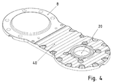
Figur 4Lagerdeckels 8 gezeigt. - In der
Figur 5
- In the
FIG. 1 is a cross section through a transmission according to the invention is shown, wherein a drive-side lantern and a housing surrounded by him surrounded, provided on the driving shaft fan are hidden. - In the
FIG. 2 is a plan view of the inside of thebearing cap 8 is shown. - In the
FIG. 3 is shown an oblique view of the transmission. - In the
FIG. 4 an oblique view is shown on the outside of thebearing cap 8. - In the
FIG. 5 is an oblique view is shown on the outside of the transmission according to the invention, wherein the input-side lantern flange and surrounded by him housing forming, provided on the driving shaft fan are shown.
Dabei ist ein zentrales Gehäuseteil 14 vorgesehen, welches Lager der Wellen des Getriebes aufnimmt und an Bereichen seiner Außenoberfläche Kühlrippen und oberflächenvergrößernde wellenartige Ausformungen aufweist.In this case, a
Die eintreibende Welle 4 ist über ein Lager 5 und ein Lager 15 im zentralen Gehäuseteil 14 gelagert und weist axial zwischen den Lagern 5 und 15 eine Ritzelverzahnung auf. Alternativ ist dort auch ein eintreibendes Verzahnteil kraftschlüssig und/oder formschlüssig verbindbar.The driving
Diese Ritzelverzahnung beziehungsweise dieses Verzahnteil ist im Eingriff mit einem Verzahnteil einer Zwischenwelle, die über Lager (5, 13) ebenfalls im zentralen Gehäuseteil 14 aufgenommen ist. Dabei befindet sich das Verzahnteil der Zwischenwelle und ein weiteres Verzahnteil der Zwischenwelle axial wiederum zwischen den Lagern (5, 13).This pinion toothing or toothed part is in engagement with a toothed part of an intermediate shaft, which is also received in the
Das weitere auf der Zwischenwelle kraftschlüssig und/oder formschlüssig verbundene Verzahnteil steht im Eingriff mit einem Verzahnteil, das kraftschlüssig und/oder formschlüssig mit der abtreibenden Welle 11 verbunden ist.The further on the intermediate shaft frictionally and / or positively connected toothed part is engaged with a toothed part, which is non-positively and / or positively connected to the driven
Vorzugsweise ist die Bauform, also die Ausrichtung des Getriebes in der das Getriebe umfassenden Maschine oder Anlage derart, dass die abtreibende Welle nach unten, also in Gravitationsrichtung, herausragt.Preferably, the design, so the orientation of the transmission in the machine or system comprising the transmission such that the driven shaft protrudes downward, ie in the direction of gravity.
Die abtreibende Welle ist über ein unteres Lager 12 und ein oberes Lager 16 im zentralen Gehäuseteil 14 gelagert.The aborting shaft is mounted on a
Im axialen Bereich des unteren Lagers 12 ist eine Fettschmierung vorgesehen. Hierzu sind Bohrkanäle 10 im zentralen Gehäuseteil 14 ausgeführt, so dass ein Kanal von der Oberseite zum axialen Bereich des unteren Lagers gebildet ist. Der Kanal 10 mündet an der Oberseite über eine Anschlussvorrichtung für Fettschmierung, die auch verschließbar ist. Auf diese Weise ist bei Wartung des Getriebes Fett unter Druck einbringbar und somit der axiale Bereich des Lagers auf der unteren Seite in komfortabler Weise von der anderen Seite des Getriebes, also der Oberseite, aus versorgbar. Daher darf das Getriebe in eine derartige Maschine oder Anlage eingebaut werden" in welcher die Unterseite unzugänglich ist. Trotzdem ist eine Wartungsschmierung in einfacher Weise ermöglicht. Insgesamt ist der Kanal 10 aus axial und radial verlaufenden Teilabschnitten zusammengesetzt, die jeweils als Bohrungen ausgeführt sind, wobei bei durchgehenden Bohrungen die jeweils ungenutzten Endbereiche der Bohrungen verschlossen sind, vorzugsweise mit einem Verschlussstopfen.In the axial region of the
An der Oberseite ist ein Lagerdeckel 8 vorgesehen, welcher die Lageraufnahmebereiche der Lager 5, 16 und 17 abdeckt, wobei im vom Lagerdeckel 8 abgedeckten Oberflächenbereich des zentralen Gehäuseteils 14 eine Nutenstruktur eingearbeitet ist, so dass nach Aufsetzen des Lagerdeckels 8 Kanäle zum Durchleiten des Öls gebildet sind. Außerdem ist in dem abgedeckten Oberflächenbereich auch eine großflächige Vertiefung ausgebildet, so dass ein flacher Raumbereich zur Aufnahme von Öl gebildet ist, in welchen die Kanäle münden.At the top of a
Alternativ oder zusätzlich ist die Nutenstruktur und die flächige Ausnehmung auch auf der Innenseite des Lagerdeckels 8 ausgebildet.
Dabei weist der Lagerdeckel 8 eine Ausnehmung 20 zur Durchführung der eintreibenden Welle auf, so dass oberhalb des zentralen Gehäuseteils 14 an der eintreibenden Welle ein Lüfter 6 verbunden, insbesondere kraftschlüssig und/oder formschlüssig, ist. Somit ist dieser Lüfter 6 in einem Gehäuseteil gehäusebildend umgeben, das als Laternenflansch 18 mit radial nach außen gerichteten Ausnehmungen 7 ausgebildet ist und auf das zentrale Gehäuseteil 14 aufgesetzt und verbunden ist.Alternatively or additionally, the groove structure and the planar recess are also formed on the inside of the
In this case, the
Der vom Lüfter 6 erzeugte Luftstrom strömt am Lagerdeckel 8 vorbei, das an seiner Außenseite eine oberflächenvergrößernde wellige Kühlstruktur aufweist. Somit wird das an der Innenseite des Lagerdeckels 8 vorhandene Öl beim Durchströmen des flächigen Raumbereichs 21, insbesondere also eines taschenartigen Raumbereichs, gekühlt.The air flow generated by the
Der Lagerdeckel 8 ist im Bereich der Stirnseiten der Zwischenwelle und der abtreibenden Welle geschlossen ausgeführt und stellt somit eine Abdeckung 22 des Wellenendes der Zwischenwelle und Abdeckung 26 der abtreibenden Welle dar.The
Aus dem Raumbereich 21 führen Ölkanäle 24 und 27 heraus und sind verbunden mit den Nuten (23, 25, 28, 29) zur Ölführung, mittels welcher Öl zu den Lagern der Abtriebswelle, der Zwischenwelle und/oder der eintreibenden Welle geführt wird, so dass diese stets ausreichend geschmiert sind, insbesondere beim Anlaufen des Getriebes.From the
Somit ist der dünnwandig ausgeführte Lagerdeckel 8 als Kühlkörper wirksam, da er auf der Oberseite des Getriebes angeordnet ist und somit dem Kühlluftstrom des auf der eintreibenden Welle oder in einem anderen Ausführungsbeispiel alternativ auf einer Zwischenwelle angeordneten Lüfters ausgesetzt. Durch die Ausbildung des düsenartig ausgeformten Laternenflansches ist ein besonders geringer Strömungswiderstand erreichbar. Die Öffnungen für den Luftdurchtritt sind seitlich angebracht, also in radialer Richtung, so dass die durchtretendes Luft nicht auf die antreibende Vorrichtung, insbesondere also Elektromotor, trifft.Thus, the thin-walled
Am zentralen Gehäuseteil 14 sind Wände ausgebildet, die den Öltank begrenzen. Durch den Öltank, der eine geringere Grundfläche aufweist als das Getriebe, insbesondere eine Grundfläche, die weniger als 30% der Grundfläche des Getriebes beträgt, ist es ermöglicht, dass insbesondere auch bei Stillstand des Getriebes das Öl sich im Öltank sammelt und daher ein hoher Ölstand erreichbar ist. Somit ist ein Ansaugrohr einer Ölpumpe 19 stets unter dem Ölstand, also unterhalb der Oberfläche des im Öltank sich befindenden Öls. Ein Ansaugen von Luft ist somit vermieden.At the
Vom Öltank zur Ölpumpe ist als Ansaugrohr ein Kanal im zentralen Gehäuseteil 14 angeordnet, der aus den Abschnitten 1 und 2 zusammengesetzt ist. Ausgangsseitig ist die Ölpumpe 19 an den Kanal 3 angeschlossen, der in durch die Ausnehmung im Lagerdeckel 8 gebildete Öltasche 21 mündet. Somit wird das warme Öl von der Ölpumpe 19 am Lagerdeckel 8 vorbeigeführt und dabei gekühlt.From the oil tank to the oil pump, a channel is arranged in the
Eine der Wände des Öltanks weist Aufnahmen für ein Lager der eintreibenden Welle und ein Lager der Zwischenwelle auf. In der Wand, die vorzugsweise die Oberseite des Öltanks darstellt, und/oder im zentralen Gehäuseteil 14 sind Kanäle eingearbeitet, insbesondere als Bohrungen, so dass Öl aus dem Getriebeinnenraum in den Öltank abfließt. Insbesondere bei Stillsetzen des Getriebes fließt das Öl in den Öltank.One of the walls of the oil tank has receptacles for a bearing of the driving shaft and a bearing of the intermediate shaft. In the wall, which is preferably the top of the oil tank, and / or in the
Den Öltank begrenzende Seitenwände weisen an ihrer Außenseite Kühlrippen 30 auf, so dass eine Entwärmung des Öls im Öltank effektiv ermöglicht ist. Die Unterseite des Öltanks ist durch einen mit dem zentralen Gehäuseteil 14 dicht verbundenen Deckel gebildet. Dieser Deckel weist an seiner Außenseite eine oberflächenvergrößernde Welligkeit auf, so dass auch hierdurch die Entwärmung des Öls im Öltank verbessert ist.Side walls delimiting the oil tank have
Weitere Kühlrippen 31 sind am zentralen Gehäuseteil vorgesehen im Bereich der Lageraufnahme des Lagers 12 der abtreibenden Welle 11.
Somit ist einerseits das Gehäuse des Getriebes möglichst kompakt ausgeführt, wobei durch die Kühlrippenstrukturen und oberflächenvergrößernde Maßnahmen im Wesentlichen ein quaderförmiges Raumvolumen erreicht wird.Thus, on the one hand, the housing of the transmission is designed to be as compact as possible, which is achieved by the cooling fin structures and surface enlarging measures essentially a cuboid space volume.
Durch die im zentralen Gehäuseteil 14 eingebrachten Bohrungen, welche als Ölkanäle wirksam sind, ist eine verbesserte Wärmeabfuhr vom Öl ans Gehäuse und von dort an die Umgebung erreicht. Insbesondere ist das Öl und das zentrale Gehäuseteil 14 auf möglichst gleichem Temperaturniveau.By introduced in the
Das untere Lager 12 der abtreibenden Welle ist in einer Lageraufnahme des zentralen Gehäuseteils 14 aufgenommen, wobei ein Teilbereich der Lageraufnahme auch eine Wand für den Öltank bildet, also diesen zumindest teilweise begrenzt.The
Das zentrale Gehäuseteil ist vorzugsweise zweistückig ausgeführt. Somit sind im unteren Stück die Lageraufnahmen für die Lager (12, 13, 15) und der Öltank angeordnet und im oberen Stück die Lageraufnahmen für die Lager (5, 16, 17), die mittels des auf das obere Stück verbundenen Lagerdeckels 8 abgedeckt sind. Außerdem ist der Laternenflansch auf das obere Stück gesetzt und verbunden.The central housing part is preferably designed in two pieces. Thus, in the lower part of the bearing mounts for the bearings (12, 13, 15) and the oil tank are arranged and in the upper piece, the bearing mounts for the bearings (5, 16, 17), which are covered by means connected to the upper
Das obere Stück des zentralen Gehäuseteils 14 weist an seiner Oberseite einen Bereich mit wellenartiger Ausbreitung auf, so dass auch hier eine oberflächenvergrößernde Struktur vorgesehen ist. Dieser Bereich ist an der Außenseite des Bereichs der Lageraufnahme für das obere Lager 16 angeordnet.The upper part of the
Ein Gehäusedeckel 32 deckt eine Öffnung im zentralen Gehäuseteil ab, so dass eine einfachere Montage ausführbar ist. Dieser Gehäusedeckel 32 weist ebenfalls eine wellenartige äußere Oberfläche als oberflächenvergrößernde Struktur auf.A
Wichtig ist dabei auch, dass am unteren Stück des zentralen Gehäuseteils 14 Kühlrippen (30, 31) ausgebildet sind, wobei diese auch auf der Unterseite des Stücks angeordnet sind. Somit ist es ermöglicht, dass die abtreibende Welle 11 einen Lüfter antreibt und der in axialer Richtung angetriebene Luftstrom dann auf die Kühlrippen (30, 31) trifft. Hierdurch ist eine effektive Kühlung der Unterseite des Getriebes ermöglicht und somit insbesondere eine effektive Kühlung des im Öltank sich befindenden Öls und des unteren Lagers der abtreibenden Welle. Der abtriebsseitig erzeugte Luftstrom gelangt aber nur in geringem Umfang an die Oberseite. Daher ist an der eintreibenden Welle der Lüfter 6 aufgesetzt und kühlt den Lagerdeckel 8, so dass das an der Innenseite des Lagerdeckels 8 vorbeiströmende Öl gekühlt wird. Das im Öltank an der unteren Seite und vom Lagerdeckel an der Oberseite gekühlte Öl strömt dann den Lagern und den zu schmierenden Teilen des Getriebes, insbesondere auch den miteinander im Eingriff stehenden Verzahnungsbereichen zu und kühlt diese auch.It is also important that at the lower part of the
Bei weiteren erfindungsgemäßen Ausführungsbeispielen ist die Ölpumpe 19 zusätzlich in Reihe geschaltet mit einem Ölfilter, so dass metallischer Abrieb aus dem Öl herausfilterbar ist. Alternativ oder zusätzlich ist auch im Getriebe, insbesondere im Öltank des Getriebes ein Filter und/oder ein Dauermagnet anordenbar, so dass die metallischen, insbesondere magnetisierbaren, Partikel dort herausfilterbar sind. Zusätzlich oder alternativ sind die vom Getriebeinneren in den Öltank führenden Kanäle mit einem derart geringen Querschnitt ausgeführt, dass entsprechend zu große Partikel herausgefiltert werden. Somit sind die Kanäle als Filterstruktur wirksam.In further embodiments of the invention, the
- 11
- ÖlkanalabschnittOil duct section
- 22
- ÖlkanalabschnittOil duct section
- 33
- ÖlkanalabschnittOil duct section
- 44
- eintreibende Welledriving wave
- 55
- Lagercamp
- 66
- LüfterFan
- 77
- Ausnehmungen, insbesondere Luftdurchtrittsöffnungen im LaternenflanschRecesses, in particular air passage openings in the lantern flange
- 88th
- Lagerdeckelbearing cap
- 99
- Anschlussvorrichtung für FettschmierungConnection device for grease lubrication
- 1010
- Bohrung als FettkanalBore as a grease channel
- 1111
- abtreibende Welleabortive wave
- 1212
- Lagercamp
- 1313
- Lagercamp
- 1414
- zentrales Gehäuseteilcentral housing part
- 1515
- Lagercamp
- 1616
- Lagercamp
- 1717
- Lagercamp
- 1818
- Gehäuseteil, insbesondere LaternenflanschHousing part, in particular lantern flange
- 1919
- Ölpumpeoil pump
- 2020
- Ausnehmung zur Durchführung der eintreibenden WelleRecess for the implementation of the driving shaft
- 2121
- Öltasche, Raumbereich für ÖlOil pocket, room area for oil
- 2222
- Abdeckung des Wellenendes der ZwischenwelleCover of the shaft end of the intermediate shaft
- 2323
- Nut zur ÖlführungGroove to the oil guide
- 2424
- Ölkanaloil passage
- 2525
- Nut zur ÖlführungGroove to the oil guide
- 2626
- Abdeckung des Wellenendes der abtreibenden WelleCover of the shaft end of the aborting shaft
- 2727
- Ölkanaloil passage
- 2828
- Nut zur ÖlführungGroove to the oil guide
- 2929
- Nut zur ÖlführungGroove to the oil guide
- 3030
- Kühlrippencooling fins
- 3131
- Kühlrippencooling fins
- 3232
- seitlicher Gehäusedeckel mit wellenartiger Struktur zur Oberflächenvergrößerunglateral housing cover with wave-like structure for surface enlargement
- 3333
- wellenartige Struktur zur Oberflächenvergrößerungwave-like structure for surface enlargement
Claims (12)
- Gearing device, in particular gearing,
wherein the gearing device has a housing having a central housing part (14), which receives a bearing of an output shaft (11) and a bearing of an input shaft (4),
wherein there is arranged in the housing an oil tank which is at least partly bounded by the central housing part,
wherein the gearing device is mounted in a machine or system, in particular a cooling tower system, in such a manner that the output shaft (11) protrudes downwards, i.e. in the direction of gravity, from the housing,
wherein the underside of the oil tank is formed by a cover leaktightly connected to the central housing part (14),
wherein the oil tank is connected to an oil pump (19) via a first duct (1,2),
characterised in that the cover has on its outside a surface-increasing waviness, and
in that the first duct (1,2) is formed as a cutout in the central housing part (14), in particular wherein the duct is composed of bore sections, in particular running axially, i.e. parallel to the axial direction of the output shaft (11), and bore sections running transversely thereto. - Gearing device according to Claim 1,
characterised in that
further ducts are formed in the central housing part (14), which ducts lead from a gearing interior space into the oil tank,
in particular wherein the further ducts are each composed of bore sections, in particular running axially, i.e. parallel to the axial direction of the output shaft (11), and bore sections running transversely thereto. - Gearing device according to at least one of the preceding claims,
characterised in that
in the central housing part (14) a second duct runs from the oil pump (19) to a top side of the gearing device, wherein a mouth region is covered by a bearing cover (8), which also covers an end side of one of the axial end regions of the output shaft (11), and opens into a spatial region, in particular an oil pocket (21), which is bounded at least by the central housing part (14) and by the bearing cover (8). - Gearing device according to Claim 3,
characterised in that
additional ducts lead from the spatial region to regions in an interior space of the gearing device which are to be lubricated and/or cooled, in particular to a bearing and/or to a region of toothings in engagement with one another. - Gearing device according to Claim 3 or 4,
characterised in that
on the input shaft (4) a fan (6) is connected in a form-locking and/or force-locking manner, the cooling air flow of which flows past the bearing cover (8), in particular wherein the cooling air flow passes through cutouts (7) of a lantern flange, in particular in the radial direction with respect to the input shaft (4), in particular wherein the lantern flange is connected to the housing, in particular to the central housing part (14) of the gearing device and, on its side facing away from the gearing device, is connected to a motor housing. - Gearing device according to at least one of the preceding claims,
characterised in that
the central housing part (14) is of two-piece design, so that an upper and lower piece are present, wherein at least one duct is led through from the upper piece into the lower piece. - Gearing device according to Claim 6,
characterised in that
the lower piece of the central housing part (14) has, on its underside, cooling ribs (30, 31), in particular wherein cooling ribs (30, 31) are formed on a wall of the lower piece at least partly bounding the oil tank and/or wherein cooling ribs (30, 31) are formed on a wall of the lower piece at least partly bounding a bearing receptacle of the bearing of the output shaft (11). - Gearing device according to one of Claims 6 or 7, characterised in that
a wave-like structure is formed on the top side of the upper piece as a surface-increasing region. - Gearing device at least according to Claim 3, characterised in that
a wave-like structure is formed on the outside of the bearing cover (8) as a surface-increasing region, which structure is arranged in the cooling air flow of the fan (6). - Gearing device at least according to Claim 6, characterised in that
a housing cover is connected to the lower and to the upper piece of the central housing part (14), wherein the housing cover is laterally arranged and/or has a wave-like structure as a surface-increasing region. - Gearing device at least according to Claim 6, characterised in that
a third duct (10), in particular a duct (10) composed of radially and axially running bore sections, is provided in the central housing part (14),
wherein the third duct (10) is led through from the upper piece into the lower piece,
wherein the third duct (10) leads from the top side to the region of a lower bearing of the output shaft (11) which is grease-lubricated, wherein a relubrication by introducing grease into a mouth region on the top side of the gearing device is performable. - Gearing device according to at least one of the preceding claims,
characterised in that
a fastening region is integrally formed on the central housing part (14), in particular on a corner region of the cuboid-shaped lower piece, in particular on the lower piece, which fastening region extends in the lateral, i.e. radial direction, in such a manner that a through-bore running in the axial direction is formed, so that a connecting screw is able to be led through in the axial direction and connected to a fixed part of a system or machine receiving the gearing device.
Applications Claiming Priority (3)
| Application Number | Priority Date | Filing Date | Title |
|---|---|---|---|
| DE102011014379 | 2011-03-17 | ||
| CN2011201469348U CN202301879U (en) | 2011-05-11 | 2011-05-11 | Speed reducer device |
| PCT/EP2012/000101 WO2012123044A1 (en) | 2011-03-17 | 2012-01-11 | Transmission device |
Publications (2)
| Publication Number | Publication Date |
|---|---|
| EP2686584A1 EP2686584A1 (en) | 2014-01-22 |
| EP2686584B1 true EP2686584B1 (en) | 2016-09-14 |
Family
ID=45491583
Family Applications (1)
| Application Number | Title | Priority Date | Filing Date |
|---|---|---|---|
| EP12700311.9A Active EP2686584B1 (en) | 2011-03-17 | 2012-01-11 | Transmission device |
Country Status (3)
| Country | Link |
|---|---|
| EP (1) | EP2686584B1 (en) |
| CN (1) | CN103649598B (en) |
| WO (1) | WO2012123044A1 (en) |
Families Citing this family (5)
| Publication number | Priority date | Publication date | Assignee | Title |
|---|---|---|---|---|
| CN104179948A (en) * | 2014-08-15 | 2014-12-03 | 丹阳荣嘉精密机械有限公司 | Gearbox cover |
| CN107956859A (en) * | 2017-10-12 | 2018-04-24 | 金洁琼 | A kind of electric car side hanging bi-motor gear box cover |
| CN107891740A (en) * | 2017-10-12 | 2018-04-10 | 金洁琼 | A kind of side hanging electric bicycle Dual-motors Driving assembly |
| BR112023021875A2 (en) * | 2021-06-15 | 2023-12-19 | Sew Eurodrive Gmbh & Co Kg | System, which features an installation device and a gear with a shaft and process for producing a gear |
| WO2023051947A1 (en) * | 2021-09-29 | 2023-04-06 | Sew-Eurodrive Gmbh & Co. Kg | Transmission with a housing part and a cover |
Family Cites Families (8)
| Publication number | Priority date | Publication date | Assignee | Title |
|---|---|---|---|---|
| US2511479A (en) * | 1945-06-28 | 1950-06-13 | Prec Developments Co Ltd | Cooling means for reduction gearing |
| US2699841A (en) * | 1949-12-17 | 1955-01-18 | Brad Foote Gear Works | Speed changing unit and lubricating means therefor |
| US2756614A (en) * | 1954-08-30 | 1956-07-31 | Illinois Tool Works | Gearing unit |
| US2832230A (en) * | 1957-10-10 | 1958-04-29 | Falk Corp | Vertical reducer |
| DE3209514C2 (en) * | 1982-03-16 | 1984-04-26 | BHS-Bayerische Berg-, Hütten- und Salzwerke AG, 8000 München | Self-contained gear system with pressure lubrication |
| DE8805009U1 (en) * | 1988-04-15 | 1988-05-26 | J.M. Voith Gmbh, 7920 Heidenheim, De | |
| DE102004030180A1 (en) * | 2004-06-22 | 2006-02-09 | A. Friedr. Flender Ag | Spur gears |
| DE102005031197B4 (en) * | 2005-07-01 | 2016-10-13 | Sew-Eurodrive Gmbh & Co Kg | Drive and fan |
-
2012
- 2012-01-11 CN CN201280012805.7A patent/CN103649598B/en active Active
- 2012-01-11 EP EP12700311.9A patent/EP2686584B1/en active Active
- 2012-01-11 WO PCT/EP2012/000101 patent/WO2012123044A1/en active Application Filing
Also Published As
| Publication number | Publication date |
|---|---|
| CN103649598B (en) | 2017-07-11 |
| EP2686584A1 (en) | 2014-01-22 |
| WO2012123044A1 (en) | 2012-09-20 |
| CN103649598A (en) | 2014-03-19 |
Similar Documents
| Publication | Publication Date | Title |
|---|---|---|
| EP2686582B1 (en) | Transmission device | |
| EP2686584B1 (en) | Transmission device | |
| EP2411706B1 (en) | Transmission | |
| EP2241787B1 (en) | Cooper for transmission, transmission with cooling device, modular system of transmission cooling devices, and type series of transmissions | |
| EP2411703B1 (en) | Transmission | |
| EP2686580B1 (en) | Transmission device | |
| EP2447576B1 (en) | Gearbox | |
| EP2923120B1 (en) | Coupling adapter | |
| EP2411704B1 (en) | Transmission | |
| DE102010054028B4 (en) | Cooling arrangement and gear motor | |
| EP3482106B1 (en) | Gear and use of a ring cooler | |
| EP2686581B1 (en) | Transmission device | |
| EP2410210A1 (en) | Transmission for industrial applications | |
| DE102019107778A1 (en) | VEHICLE DRIVE TRAIN COMPONENT WITH AN INTERNAL VENTILATION CONVERSION TUBE FOR VENTING A HOUSING OF THE VEHICLE DRIVE TRAY COMPONENT | |
| DE102011003250A1 (en) | Gear assembly for rail vehicle, has gear stage that has gear as drive wheel and another gear as drive wheel in housing, where one of gears has additional lubricant delivery element for lubricant supply | |
| EP2686583B1 (en) | Transmission device | |
| DE10016640C1 (en) | Transmission for motor vehicle has oil pipe located completely inside oil-filled space of gear case, and electrical power is supplied to heater element in communication with oil pipe | |
| EP3568611B1 (en) | Drive, having a combining transmission driven by electric motors and a transmission driven by same | |
| DE102014017696B4 (en) | Transmission, the interior of which is at least partially filled with lubricating oil | |
| DE102019218087B4 (en) | Lubricant container for a device for cooling and lubricating a vehicle transmission and a device with such a lubricant container | |
| DE102010011789A1 (en) | Device for use with industrial gears, comprises housing and functional parts, and housing of functional parts partially receives or includes space between functional parts | |
| WO2015197158A1 (en) | Drive | |
| DE102012022025A1 (en) | Gear i.e. planetary gear, has cooler attached with shell part and arranged at gear, assembled pipe line fixed with cooler, returning part arranged in pipe line, and grooves opened in edge of shell part | |
| CN103649597A (en) | Transmission device | |
| CN202048174U (en) | Decelerating device |
Legal Events
| Date | Code | Title | Description |
|---|---|---|---|
| PUAI | Public reference made under article 153(3) epc to a published international application that has entered the european phase |
Free format text: ORIGINAL CODE: 0009012 |
|
| 17P | Request for examination filed |
Effective date: 20131017 |
|
| AK | Designated contracting states |
Kind code of ref document: A1 Designated state(s): AL AT BE BG CH CY CZ DE DK EE ES FI FR GB GR HR HU IE IS IT LI LT LU LV MC MK MT NL NO PL PT RO RS SE SI SK SM TR |
|
| DAX | Request for extension of the european patent (deleted) | ||
| GRAP | Despatch of communication of intention to grant a patent |
Free format text: ORIGINAL CODE: EPIDOSNIGR1 |
|
| INTG | Intention to grant announced |
Effective date: 20160421 |
|
| GRAS | Grant fee paid |
Free format text: ORIGINAL CODE: EPIDOSNIGR3 |
|
| GRAA | (expected) grant |
Free format text: ORIGINAL CODE: 0009210 |
|
| AK | Designated contracting states |
Kind code of ref document: B1 Designated state(s): AL AT BE BG CH CY CZ DE DK EE ES FI FR GB GR HR HU IE IS IT LI LT LU LV MC MK MT NL NO PL PT RO RS SE SI SK SM TR |
|
| REG | Reference to a national code |
Ref country code: GB Ref legal event code: FG4D Free format text: NOT ENGLISH |
|
| REG | Reference to a national code |
Ref country code: CH Ref legal event code: EP |
|
| REG | Reference to a national code |
Ref country code: IE Ref legal event code: FG4D Free format text: LANGUAGE OF EP DOCUMENT: GERMAN |
|
| REG | Reference to a national code |
Ref country code: AT Ref legal event code: REF Ref document number: 829368 Country of ref document: AT Kind code of ref document: T Effective date: 20161015 |
|
| REG | Reference to a national code |
Ref country code: DE Ref legal event code: R096 Ref document number: 502012008218 Country of ref document: DE |
|
| REG | Reference to a national code |
Ref country code: FR Ref legal event code: PLFP Year of fee payment: 6 |
|
| REG | Reference to a national code |
Ref country code: LT Ref legal event code: MG4D |
|
| REG | Reference to a national code |
Ref country code: NL Ref legal event code: MP Effective date: 20160914 |
|
| PG25 | Lapsed in a contracting state [announced via postgrant information from national office to epo] |
Ref country code: NO Free format text: LAPSE BECAUSE OF FAILURE TO SUBMIT A TRANSLATION OF THE DESCRIPTION OR TO PAY THE FEE WITHIN THE PRESCRIBED TIME-LIMIT Effective date: 20161214 Ref country code: HR Free format text: LAPSE BECAUSE OF FAILURE TO SUBMIT A TRANSLATION OF THE DESCRIPTION OR TO PAY THE FEE WITHIN THE PRESCRIBED TIME-LIMIT Effective date: 20160914 Ref country code: LT Free format text: LAPSE BECAUSE OF FAILURE TO SUBMIT A TRANSLATION OF THE DESCRIPTION OR TO PAY THE FEE WITHIN THE PRESCRIBED TIME-LIMIT Effective date: 20160914 Ref country code: RS Free format text: LAPSE BECAUSE OF FAILURE TO SUBMIT A TRANSLATION OF THE DESCRIPTION OR TO PAY THE FEE WITHIN THE PRESCRIBED TIME-LIMIT Effective date: 20160914 |
|
| PG25 | Lapsed in a contracting state [announced via postgrant information from national office to epo] |
Ref country code: LV Free format text: LAPSE BECAUSE OF FAILURE TO SUBMIT A TRANSLATION OF THE DESCRIPTION OR TO PAY THE FEE WITHIN THE PRESCRIBED TIME-LIMIT Effective date: 20160914 Ref country code: GR Free format text: LAPSE BECAUSE OF FAILURE TO SUBMIT A TRANSLATION OF THE DESCRIPTION OR TO PAY THE FEE WITHIN THE PRESCRIBED TIME-LIMIT Effective date: 20161215 Ref country code: SE Free format text: LAPSE BECAUSE OF FAILURE TO SUBMIT A TRANSLATION OF THE DESCRIPTION OR TO PAY THE FEE WITHIN THE PRESCRIBED TIME-LIMIT Effective date: 20160914 Ref country code: NL Free format text: LAPSE BECAUSE OF FAILURE TO SUBMIT A TRANSLATION OF THE DESCRIPTION OR TO PAY THE FEE WITHIN THE PRESCRIBED TIME-LIMIT Effective date: 20160914 |
|
| PG25 | Lapsed in a contracting state [announced via postgrant information from national office to epo] |
Ref country code: EE Free format text: LAPSE BECAUSE OF FAILURE TO SUBMIT A TRANSLATION OF THE DESCRIPTION OR TO PAY THE FEE WITHIN THE PRESCRIBED TIME-LIMIT Effective date: 20160914 Ref country code: RO Free format text: LAPSE BECAUSE OF FAILURE TO SUBMIT A TRANSLATION OF THE DESCRIPTION OR TO PAY THE FEE WITHIN THE PRESCRIBED TIME-LIMIT Effective date: 20160914 |
|
| PG25 | Lapsed in a contracting state [announced via postgrant information from national office to epo] |
Ref country code: ES Free format text: LAPSE BECAUSE OF FAILURE TO SUBMIT A TRANSLATION OF THE DESCRIPTION OR TO PAY THE FEE WITHIN THE PRESCRIBED TIME-LIMIT Effective date: 20160914 Ref country code: CZ Free format text: LAPSE BECAUSE OF FAILURE TO SUBMIT A TRANSLATION OF THE DESCRIPTION OR TO PAY THE FEE WITHIN THE PRESCRIBED TIME-LIMIT Effective date: 20160914 Ref country code: SK Free format text: LAPSE BECAUSE OF FAILURE TO SUBMIT A TRANSLATION OF THE DESCRIPTION OR TO PAY THE FEE WITHIN THE PRESCRIBED TIME-LIMIT Effective date: 20160914 Ref country code: BG Free format text: LAPSE BECAUSE OF FAILURE TO SUBMIT A TRANSLATION OF THE DESCRIPTION OR TO PAY THE FEE WITHIN THE PRESCRIBED TIME-LIMIT Effective date: 20161214 Ref country code: BE Free format text: LAPSE BECAUSE OF NON-PAYMENT OF DUE FEES Effective date: 20170131 Ref country code: PL Free format text: LAPSE BECAUSE OF FAILURE TO SUBMIT A TRANSLATION OF THE DESCRIPTION OR TO PAY THE FEE WITHIN THE PRESCRIBED TIME-LIMIT Effective date: 20160914 Ref country code: IS Free format text: LAPSE BECAUSE OF FAILURE TO SUBMIT A TRANSLATION OF THE DESCRIPTION OR TO PAY THE FEE WITHIN THE PRESCRIBED TIME-LIMIT Effective date: 20170114 Ref country code: PT Free format text: LAPSE BECAUSE OF FAILURE TO SUBMIT A TRANSLATION OF THE DESCRIPTION OR TO PAY THE FEE WITHIN THE PRESCRIBED TIME-LIMIT Effective date: 20170116 Ref country code: SM Free format text: LAPSE BECAUSE OF FAILURE TO SUBMIT A TRANSLATION OF THE DESCRIPTION OR TO PAY THE FEE WITHIN THE PRESCRIBED TIME-LIMIT Effective date: 20160914 |
|
| REG | Reference to a national code |
Ref country code: DE Ref legal event code: R097 Ref document number: 502012008218 Country of ref document: DE |
|
| PLBE | No opposition filed within time limit |
Free format text: ORIGINAL CODE: 0009261 |
|
| STAA | Information on the status of an ep patent application or granted ep patent |
Free format text: STATUS: NO OPPOSITION FILED WITHIN TIME LIMIT |
|
| PG25 | Lapsed in a contracting state [announced via postgrant information from national office to epo] |
Ref country code: DK Free format text: LAPSE BECAUSE OF FAILURE TO SUBMIT A TRANSLATION OF THE DESCRIPTION OR TO PAY THE FEE WITHIN THE PRESCRIBED TIME-LIMIT Effective date: 20160914 |
|
| 26N | No opposition filed |
Effective date: 20170615 |
|
| REG | Reference to a national code |
Ref country code: CH Ref legal event code: PL |
|
| PG25 | Lapsed in a contracting state [announced via postgrant information from national office to epo] |
Ref country code: MC Free format text: LAPSE BECAUSE OF FAILURE TO SUBMIT A TRANSLATION OF THE DESCRIPTION OR TO PAY THE FEE WITHIN THE PRESCRIBED TIME-LIMIT Effective date: 20160914 |
|
| PG25 | Lapsed in a contracting state [announced via postgrant information from national office to epo] |
Ref country code: LI Free format text: LAPSE BECAUSE OF NON-PAYMENT OF DUE FEES Effective date: 20170131 Ref country code: CH Free format text: LAPSE BECAUSE OF NON-PAYMENT OF DUE FEES Effective date: 20170131 |
|
| REG | Reference to a national code |
Ref country code: IE Ref legal event code: MM4A |
|
| PG25 | Lapsed in a contracting state [announced via postgrant information from national office to epo] |
Ref country code: LU Free format text: LAPSE BECAUSE OF NON-PAYMENT OF DUE FEES Effective date: 20170111 Ref country code: SI Free format text: LAPSE BECAUSE OF FAILURE TO SUBMIT A TRANSLATION OF THE DESCRIPTION OR TO PAY THE FEE WITHIN THE PRESCRIBED TIME-LIMIT Effective date: 20160914 |
|
| REG | Reference to a national code |
Ref country code: FR Ref legal event code: PLFP Year of fee payment: 7 |
|
| REG | Reference to a national code |
Ref country code: BE Ref legal event code: MM Effective date: 20170131 |
|
| PG25 | Lapsed in a contracting state [announced via postgrant information from national office to epo] |
Ref country code: IE Free format text: LAPSE BECAUSE OF NON-PAYMENT OF DUE FEES Effective date: 20170111 |
|
| REG | Reference to a national code |
Ref country code: AT Ref legal event code: MM01 Ref document number: 829368 Country of ref document: AT Kind code of ref document: T Effective date: 20170111 |
|
| PG25 | Lapsed in a contracting state [announced via postgrant information from national office to epo] |
Ref country code: AT Free format text: LAPSE BECAUSE OF NON-PAYMENT OF DUE FEES Effective date: 20170111 |
|
| PG25 | Lapsed in a contracting state [announced via postgrant information from national office to epo] |
Ref country code: MT Free format text: LAPSE BECAUSE OF FAILURE TO SUBMIT A TRANSLATION OF THE DESCRIPTION OR TO PAY THE FEE WITHIN THE PRESCRIBED TIME-LIMIT Effective date: 20160914 |
|
| PG25 | Lapsed in a contracting state [announced via postgrant information from national office to epo] |
Ref country code: AL Free format text: LAPSE BECAUSE OF FAILURE TO SUBMIT A TRANSLATION OF THE DESCRIPTION OR TO PAY THE FEE WITHIN THE PRESCRIBED TIME-LIMIT Effective date: 20160914 |
|
| PG25 | Lapsed in a contracting state [announced via postgrant information from national office to epo] |
Ref country code: HU Free format text: LAPSE BECAUSE OF FAILURE TO SUBMIT A TRANSLATION OF THE DESCRIPTION OR TO PAY THE FEE WITHIN THE PRESCRIBED TIME-LIMIT; INVALID AB INITIO Effective date: 20120111 |
|
| PG25 | Lapsed in a contracting state [announced via postgrant information from national office to epo] |
Ref country code: CY Free format text: LAPSE BECAUSE OF NON-PAYMENT OF DUE FEES Effective date: 20160914 |
|
| PG25 | Lapsed in a contracting state [announced via postgrant information from national office to epo] |
Ref country code: MK Free format text: LAPSE BECAUSE OF FAILURE TO SUBMIT A TRANSLATION OF THE DESCRIPTION OR TO PAY THE FEE WITHIN THE PRESCRIBED TIME-LIMIT Effective date: 20160914 |
|
| PG25 | Lapsed in a contracting state [announced via postgrant information from national office to epo] |
Ref country code: TR Free format text: LAPSE BECAUSE OF FAILURE TO SUBMIT A TRANSLATION OF THE DESCRIPTION OR TO PAY THE FEE WITHIN THE PRESCRIBED TIME-LIMIT Effective date: 20160914 |
|
| PGFP | Annual fee paid to national office [announced via postgrant information from national office to epo] |
Ref country code: IT Payment date: 20221213 Year of fee payment: 12 Ref country code: DE Payment date: 20230131 Year of fee payment: 12 |
|
| PGFP | Annual fee paid to national office [announced via postgrant information from national office to epo] |
Ref country code: GB Payment date: 20231130 Year of fee payment: 13 |
|
| PGFP | Annual fee paid to national office [announced via postgrant information from national office to epo] |
Ref country code: FR Payment date: 20231212 Year of fee payment: 13 Ref country code: FI Payment date: 20231218 Year of fee payment: 13 |