EP2686172B1 - Mehrschichtkörper - Google Patents
Mehrschichtkörper Download PDFInfo
- Publication number
- EP2686172B1 EP2686172B1 EP12709049.6A EP12709049A EP2686172B1 EP 2686172 B1 EP2686172 B1 EP 2686172B1 EP 12709049 A EP12709049 A EP 12709049A EP 2686172 B1 EP2686172 B1 EP 2686172B1
- Authority
- EP
- European Patent Office
- Prior art keywords
- facet
- region
- layer
- axis
- facet surfaces
- Prior art date
- Legal status (The legal status is an assumption and is not a legal conclusion. Google has not performed a legal analysis and makes no representation as to the accuracy of the status listed.)
- Active
Links
Images


Classifications
-
- G—PHYSICS
- G02—OPTICS
- G02B—OPTICAL ELEMENTS, SYSTEMS OR APPARATUS
- G02B5/00—Optical elements other than lenses
- G02B5/18—Diffraction gratings
-
- B—PERFORMING OPERATIONS; TRANSPORTING
- B29—WORKING OF PLASTICS; WORKING OF SUBSTANCES IN A PLASTIC STATE IN GENERAL
- B29D—PRODUCING PARTICULAR ARTICLES FROM PLASTICS OR FROM SUBSTANCES IN A PLASTIC STATE
- B29D11/00—Producing optical elements, e.g. lenses or prisms
- B29D11/0074—Production of other optical elements not provided for in B29D11/00009- B29D11/0073
-
- B—PERFORMING OPERATIONS; TRANSPORTING
- B32—LAYERED PRODUCTS
- B32B—LAYERED PRODUCTS, i.e. PRODUCTS BUILT-UP OF STRATA OF FLAT OR NON-FLAT, e.g. CELLULAR OR HONEYCOMB, FORM
- B32B15/00—Layered products comprising a layer of metal
- B32B15/04—Layered products comprising a layer of metal comprising metal as the main or only constituent of a layer, which is next to another layer of the same or of a different material
-
- B—PERFORMING OPERATIONS; TRANSPORTING
- B32—LAYERED PRODUCTS
- B32B—LAYERED PRODUCTS, i.e. PRODUCTS BUILT-UP OF STRATA OF FLAT OR NON-FLAT, e.g. CELLULAR OR HONEYCOMB, FORM
- B32B3/00—Layered products comprising a layer with external or internal discontinuities or unevennesses, or a layer of non-planar shape; Layered products comprising a layer having particular features of form
- B32B3/26—Layered products comprising a layer with external or internal discontinuities or unevennesses, or a layer of non-planar shape; Layered products comprising a layer having particular features of form characterised by a particular shape of the outline of the cross-section of a continuous layer; characterised by a layer with cavities or internal voids ; characterised by an apertured layer
- B32B3/30—Layered products comprising a layer with external or internal discontinuities or unevennesses, or a layer of non-planar shape; Layered products comprising a layer having particular features of form characterised by a particular shape of the outline of the cross-section of a continuous layer; characterised by a layer with cavities or internal voids ; characterised by an apertured layer characterised by a layer formed with recesses or projections, e.g. hollows, grooves, protuberances, ribs
-
- B—PERFORMING OPERATIONS; TRANSPORTING
- B42—BOOKBINDING; ALBUMS; FILES; SPECIAL PRINTED MATTER
- B42D—BOOKS; BOOK COVERS; LOOSE LEAVES; PRINTED MATTER CHARACTERISED BY IDENTIFICATION OR SECURITY FEATURES; PRINTED MATTER OF SPECIAL FORMAT OR STYLE NOT OTHERWISE PROVIDED FOR; DEVICES FOR USE THEREWITH AND NOT OTHERWISE PROVIDED FOR; MOVABLE-STRIP WRITING OR READING APPARATUS
- B42D25/00—Information-bearing cards or sheet-like structures characterised by identification or security features; Manufacture thereof
- B42D25/20—Information-bearing cards or sheet-like structures characterised by identification or security features; Manufacture thereof characterised by a particular use or purpose
- B42D25/29—Securities; Bank notes
-
- B—PERFORMING OPERATIONS; TRANSPORTING
- B42—BOOKBINDING; ALBUMS; FILES; SPECIAL PRINTED MATTER
- B42D—BOOKS; BOOK COVERS; LOOSE LEAVES; PRINTED MATTER CHARACTERISED BY IDENTIFICATION OR SECURITY FEATURES; PRINTED MATTER OF SPECIAL FORMAT OR STYLE NOT OTHERWISE PROVIDED FOR; DEVICES FOR USE THEREWITH AND NOT OTHERWISE PROVIDED FOR; MOVABLE-STRIP WRITING OR READING APPARATUS
- B42D25/00—Information-bearing cards or sheet-like structures characterised by identification or security features; Manufacture thereof
- B42D25/30—Identification or security features, e.g. for preventing forgery
- B42D25/324—Reliefs
-
- B—PERFORMING OPERATIONS; TRANSPORTING
- B42—BOOKBINDING; ALBUMS; FILES; SPECIAL PRINTED MATTER
- B42D—BOOKS; BOOK COVERS; LOOSE LEAVES; PRINTED MATTER CHARACTERISED BY IDENTIFICATION OR SECURITY FEATURES; PRINTED MATTER OF SPECIAL FORMAT OR STYLE NOT OTHERWISE PROVIDED FOR; DEVICES FOR USE THEREWITH AND NOT OTHERWISE PROVIDED FOR; MOVABLE-STRIP WRITING OR READING APPARATUS
- B42D25/00—Information-bearing cards or sheet-like structures characterised by identification or security features; Manufacture thereof
- B42D25/30—Identification or security features, e.g. for preventing forgery
- B42D25/328—Diffraction gratings; Holograms
-
- B—PERFORMING OPERATIONS; TRANSPORTING
- B42—BOOKBINDING; ALBUMS; FILES; SPECIAL PRINTED MATTER
- B42D—BOOKS; BOOK COVERS; LOOSE LEAVES; PRINTED MATTER CHARACTERISED BY IDENTIFICATION OR SECURITY FEATURES; PRINTED MATTER OF SPECIAL FORMAT OR STYLE NOT OTHERWISE PROVIDED FOR; DEVICES FOR USE THEREWITH AND NOT OTHERWISE PROVIDED FOR; MOVABLE-STRIP WRITING OR READING APPARATUS
- B42D25/00—Information-bearing cards or sheet-like structures characterised by identification or security features; Manufacture thereof
- B42D25/40—Manufacture
- B42D25/45—Associating two or more layers
-
- B—PERFORMING OPERATIONS; TRANSPORTING
- B32—LAYERED PRODUCTS
- B32B—LAYERED PRODUCTS, i.e. PRODUCTS BUILT-UP OF STRATA OF FLAT OR NON-FLAT, e.g. CELLULAR OR HONEYCOMB, FORM
- B32B2307/00—Properties of the layers or laminate
- B32B2307/40—Properties of the layers or laminate having particular optical properties
-
- B—PERFORMING OPERATIONS; TRANSPORTING
- B32—LAYERED PRODUCTS
- B32B—LAYERED PRODUCTS, i.e. PRODUCTS BUILT-UP OF STRATA OF FLAT OR NON-FLAT, e.g. CELLULAR OR HONEYCOMB, FORM
- B32B2551/00—Optical elements
-
- B42D2033/18—
-
- B42D2035/20—
-
- Y—GENERAL TAGGING OF NEW TECHNOLOGICAL DEVELOPMENTS; GENERAL TAGGING OF CROSS-SECTIONAL TECHNOLOGIES SPANNING OVER SEVERAL SECTIONS OF THE IPC; TECHNICAL SUBJECTS COVERED BY FORMER USPC CROSS-REFERENCE ART COLLECTIONS [XRACs] AND DIGESTS
- Y10—TECHNICAL SUBJECTS COVERED BY FORMER USPC
- Y10T—TECHNICAL SUBJECTS COVERED BY FORMER US CLASSIFICATION
- Y10T428/00—Stock material or miscellaneous articles
- Y10T428/24—Structurally defined web or sheet [e.g., overall dimension, etc.]
- Y10T428/24355—Continuous and nonuniform or irregular surface on layer or component [e.g., roofing, etc.]
Definitions
- the invention relates to a multilayer body, in particular in the form of a transfer film, a laminating film, a packaging film, a decorative element or security element, and a method for producing such a multilayer body.
- Security documents with a diffractive optical security element are for example from EP 0 105 099 B1 and the EP 0 375 833 B1 known.
- diffraction gratings are molded into a layer of a multilayer body and covered with a metallic reflection layer. By diffracting the incident light at these diffraction gratings, an optically variable effect is generated, which is determined by the spatial frequency of the diffraction gratings and their azimuth angle.
- the diffraction structure formed such that moves at a given lighting and observation direction color pattern with locally predetermined speed in a predetermined path when the substrate is rotated in its plane in a certain direction of rotation and at a certain speed.
- EP 0 375 833 B1 are the different ones Fields of a grid with a maximum dimension of less than 0.3mm occupied with different diffraction gratings, so that when viewing the security element different representations result in different viewing directions of the security element.
- achromatic surface structure is here superimposed combined with a thin-film structure.
- the achromatic structures have an order of magnitude in which diffraction phenomena have only a slight influence on the optical properties and thus the structures act essentially like tilted mirrors.
- the described security element here has partial surfaces which are covered with different achromatic surface structures, for example sawtooth structures, which have a different azimuth angle to a second partial surface in a first partial surface.
- These different sub-areas are further additionally covered with a thin-film layer structure, so that different color and contrast changes are generated in the sub-areas and creates the impression of a defined, almost discrete color change for the viewer when turning or tilting.
- the document DE 10 2005 061749 discloses an achromatic reflective microstructure in the form of a mosaic of a plurality of achromatically reflecting mosaic elements, which are characterized by the parameters size, outline shape, relief shape, reflectivity and spatial orientation.
- the invention is based on the object to provide a film body and a method for its production, which is characterized by an optically variable effect, which differs from the previously described known optically variable effects and thus has corresponding advantages in decorative and security applications.
- Pseudo-random means here that the respectively varied parameters F, S, H, P, Ax, Ay and Az can not take all possible values, but only values from a narrower, predefined range of variation.
- the pseudo-random variation can take into account all values from this narrower, predefined variation range with equal probability.
- a (mathematical) function for the probability of taking into account a value from this range of variation. Examples of such functions are the Gaussian function and an inverted Gaussian function.
- the invention is based on the finding that an optically variable effect can be generated by the shaping of the facet surfaces specified above in a layer of a multilayer body differs for the human observer from the optically variable effect obtainable by the aforementioned prior art methods.
- the optically variable effect according to the invention can be distinguished, for example, by a characteristic depth effect and / or by characteristic color and / or glitter effects.
- the optically variable effect is characterized by the fact that it has no or almost no disturbing diffractive components, such as rainbow effects.
- the optically variable effect is therefore largely achromatic. This makes it possible to achieve the greatest possible distinction from the known diffractive effects. It also helps laypersons to clearly identify the effect.
- the invention makes it possible to produce these optically variable effects particularly cost-effectively by large-scale industrial processes and to produce them in a reproducible manner.
- the optically variable effects produced by the facet surfaces of a multilayer body according to the invention can also be integrated in a film body in register with other elements which exhibit a different, optically variable effect.
- the reflective second layer may be applied over the entire surface on the facet surfaces and the surfaces between the facet surfaces, but it may also be present only on the facet surfaces or only on parts of the facet surfaces and not be present in the other surface regions. This can be achieved, for example, via so-called demetallization processes, in particular known etching processes or washing processes. Further for example, it is possible to apply to a partially existing reflective second layer, eg aluminum, a further reflective second layer, eg ZnS, which may in particular be transparent or translucent.
- the reflective second layer is provided in each case in the region of the facet surfaces in the first region and is not provided in the region not occupied by the facet surfaces.
- the second reflective layer is applied to the first layer over the entire area, at least in the first region, and then removed again in the partial regions of the first region which are not covered by the facet surfaces.
- the reflective second layer is provided in each case in the region of the facet surfaces in the first region and is not provided in a first subregion of the first region which is not covered with the facet surfaces.
- a second partial region is preferably provided in the first region, which is not covered with the facet surfaces, and in which the reflective second layer is provided. It is also possible that a plurality of first and / or second such sub-areas is provided.
- the at least one partial area and / or the at least one second partial area are preferably designed in a pattern.
- the at least one subregion forms a background region and the at least one second subregion forms a pattern region or vice versa.
- the at least one first partial region and the at least one second partial region are in this case designed such that they generate optically perceptible information for the human observer when viewed through transmitted light, which information is formed by the shaping of the at least one first partial region the at least one second subarea is determined.
- the at least one first partial region and the at least one second partial region preferably have a lateral dimension of more than 300 ⁇ m.
- the multilayer body is preferably transparent in the first subareas or in the first subarea.
- the visual appearance of the multilayer body can be further improved.
- a background structure is molded into the second surface of the first layer in a partial region of the first region which is not covered with the facet surfaces.
- the background structure is preferably formed by a diffractive and / or refractive relief structure which generates a second optical effect which differs from the optical effect of the facet surface.
- the partial area of the first area occupied by the background structure is shaped in the form of a background area which encloses one or more, preferably all, of the facet areas.
- the background structure preferably comprises a relief structure, in particular a diffractive relief structure, which generates motion and / or morphing effects as an optical effect.
- a relief structure in particular a diffractive relief structure, which generates motion and / or morphing effects as an optical effect.
- this is the with the Background structure occupied partial area divided into a plurality of zones, which are each covered with a diffractive diffraction grating, wherein at least one of the lattice parameters of adjacent zones differs, in particular the spatial frequency and / or the azimuth angle of the diffractive structures of adjacent zones.
- the background structure comprises diffractive and / or refractive microscopic relief structures which generate a macroscopic three-dimensionality similar to a refractive distortion lens or optically distorting free-form effect or another, three-dimensional effect.
- the area fraction of the partial areas of the first area occupied by the facet areas on the partial areas of the first area occupied by the background structures and the facet areas is preferably less than 70%, more preferably less than 50%, more preferably less than 30% when viewed perpendicular to the base plane.
- the centroids of adjacent facet surfaces are less than 300 microns, more preferably less than 100 microns, away from each other.
- the centroids of adjacent facet surfaces are between 2 ⁇ m and 300 ⁇ m, further between 5 ⁇ m and 100 ⁇ m, more preferably between 5 ⁇ m and 50 ⁇ m apart.
- the minimum distance between a point on an outer edge of a facet surface and a point on the outer edge of an adjacent facet surface is preferably less than 300 ⁇ m, more preferably less than 100 ⁇ m, more preferably less than 50 ⁇ m and preferably between 0 and 300 ⁇ m, more preferably between 0 ⁇ m and 100 ⁇ m, more preferably between 1 ⁇ m and 50 ⁇ m.
- This dimensioning rule preferably applies to all facet areas in the first area.
- Such an arrangement of the facet surfaces relative to one another results in particular in the arrangement of a background structure in terms of the visibility and superimposition of the optical information provided by the facet surfaces and the background structure.
- this structure preferably has a spacing of neighboring structure elements that is smaller than the wavelengths of visible light.
- structures whose depth to width ratio is greater than 0.5, more preferably greater than 1, are preferably used as structural elements for this structure.
- these structures can be used to control the demetallization of the areas of the first area that are not covered with facet areas.
- the second layer has different reflective properties in different partial areas of the first area and has a different layer structure.
- a metal layer as a reflective layer and, after Partial removal of this metal layer in the not covered with the facet areas of the first area a dielectric reflection layer over the entire surface applied, for example, a transparent or translucent HRI layer, for example, ZnS, applied, so there are two different optical effects, in the areas occupied by the facet areas In the subregions not covered by the facet faces, a color shift effect is generated due to the combination of the dielectric reflection layer and the zeroth-order diffraction structures, which occurs when the multilayer body is rotated. This optical effect is then superimposed by the optical effect already described above caused by the facet surfaces.
- the second layer has a thin-film layer system which generates a viewing angle-dependent color shift effect, in particular in the visible wavelength range.
- a thin film layer system is characterized in particular by one or more spacer layers.
- the optically effective layer thickness of these spacer layers fulfills, preferably for a certain viewing angle, the ⁇ / 2 or ⁇ / 4 condition for a wavelength In, in particular in the range of visible light.
- the thin-film layer system may in this case consist of a single layer, of a layer system with one or more dielectric layers Layers and one or more metallic layers or consist of a layer stack with two or more dielectric layers.
- HRI high refraction index
- the second layer may also have one or more further layers.
- the use of a thin-film layer system in the second layer produces interesting color-changing effects, which, with a corresponding variation of the above-mentioned parameters, are characterized by a high depth effect and colored glitter effects.
- the second layer comprises an oriented liquid crystal layer, in particular a cholesteric liquid crystal layer, a metal layer, an HRI layer or an LRI (High Refraction Index) layer, or a layer comprising a Lacquer, a magnetic pigment, an ink-doped polymer, nanoparticles or luminescent materials.
- an oriented liquid crystal layer in particular a cholesteric liquid crystal layer, a metal layer, an HRI layer or an LRI (High Refraction Index) layer, or a layer comprising a Lacquer, a magnetic pigment, an ink-doped polymer, nanoparticles or luminescent materials.
- the first layer is preferably a transparent layer, in particular a layer of a transparent replication lacquer.
- the replicate varnish surface structures are imprinted, which either fulfill an optical function (diffraction, refraction, reflection) and / or fulfill another non-optical function.
- Such structures for example a diffractive line grating of 500 to 5000 lines / mm, arranged in particular in a pattern, can serve, for example, for the molecules of the In particular, to align the pattern of the liquid crystal layer in a pattern, thereby defining its polarization effect or its polarization characteristic, in particular in a pattern.
- the multilayer body generates a visually variable first information recognizable to the human observer, the inclination angles Ax and Ay of the facet surface in the first region being varied according to a function F (x, y) in order to generate the first information.
- F a function of the parameters F, S, H, P or Az in the first region to be pseudo-randomly varied within their respective variation range predefined for the first region.
- the inclination angles Ax and Ay of the facet faces in the first region are respectively determined according to an additive or multiplicative superposition of a function F (x, y).
- certain inclination angles Ax and Ay are determined with the pseudo-random variation of the inclination angle Ax and / or the inclination angle Ay within the respective range of variation predefined for the first range.
- the function F (x, y) is in this case selected such that it varies the inclination angles Ax and Ay for generating an optically variable first information.
- the predefined variation range of the inclination angles Ax and Ay is chosen to be less than the average slope of the function F (x, y) in the first range, in particular between 0.1 times and 1.9 times the average slope of the function F. (x, y) selected. This will ensures that the first optically variable information in its appearance is not too much of additional optically variable effects such as increased depth of impression, glitter and texture effect is superimposed and the recognizability of the first information is not affected.
- the function F (x, y) preferably describes a three-dimensional free-form surface with one or more free-form elements.
- the inclination angles Ax and Ay are hereby preferably determined by the respective surface normal of the three-dimensional freeform surface in the centroid of the respective facet surface.
- the freeform elements have, for example, the shape or the outline of an alphanumeric character, a geometric figure or another object. Furthermore, the three-dimensional shaping of the free-form elements is preferably selected such that they generate a lenticular magnification, reduction or distortion effect.
- the free-form elements preferably have a lenticular shape in a sectional plane perpendicular to the base plane, for example a shape which corresponds to a corresponding section through a collection, scattering or distortion lens.
- the three-dimensional free-form surface preferably has a common base plane from which the one or more free-form elements rise or fall.
- the function F (x, y) thus describes in the area of a free-form element a free-form surface in the form of a lens or a lens transformed to represent an alphanumeric character, a geometric figure or another object.
- contour lines of the freeform elements in a sectional plane parallel to the ground plane in this case preferably corresponds to the first information and has for example the shape of a letter, a symbol, a geometric figure or any other object.
- the function F (x, y) describes a section of a surface of a three-dimensional object as a free-form element.
- the three-dimensional shape of a freeform element thus corresponds, for example, to a detail of a sculpture, an ornament or relief or another three-dimensional object, for example a building, a human person, etc.
- adjacent maxima of a free-form element in the direction of the z-axis, based on a projection onto the ground plane are more than 0.5 mm, more preferably more than 1 mm and even more preferably more than 3 mm spaced from each other.
- the smallest dimension of a free-form element in relation to a projection onto the ground plane is more than 2 mm, more preferably more than 4 mm.
- the smallest dimension of a free-form element in relation to a projection onto the ground plane is the width of the free-form element or the Spacing of those opposite edge points of the projection surface to understand that lie on a line of intersection through the centroid of the projection surface and compared to the other opposing points have the smallest spacing.
- the dimensions (length, width) of the free-form element determined by the contour of the projection surface of the free-form element on the ground plane are in the range from 2 mm to 50 mm, more preferably from 4 mm to 30 mm.
- the function F (x, y) in the region of the free-form element is continuous and differentiable and / or function F (x, y) is composed of flat and curved surface regions in the region of the free-form element, wherein preferably the radius of curvature of the curved surface areas not less than 1 mm, more preferably not less than 3mm.
- a parameter variation value is selected pseudo-randomly from a predefined group of parameter variation values.
- the predefined group preferably comprises between 3 and 30, in particular between 3 and 10 parameter variation values.
- the inclination angle Ax and / or Ay of the facet face in the first region becomes pseudo-random in a variation range of -45 ° to + 45 °, more preferably -30 ° to + 30 °, particularly preferably -15 ° to + 15 ° , in particular varies to obtain a glittering effect.
- the azimuth angle Az of the facet surfaces in the first region is advantageous to vary the azimuth angle Az of the facet surfaces in the first region pseudo-randomly in a variation range from -90 ° to + 90 °, more preferably from -45 ° to + 45 ° and particularly preferably -15 ° to + 15 °.
- the spacing H of the centroid of the facet surfaces from the ground plane in the first region is pseudorandomly varied.
- the range of variation defined by the difference between the maximum spacing H max and the minimum spacing H min , between which the spacing H of the facet area varies pseudo-randomly, is preferably between 0.5 ⁇ m and 8 ⁇ m, more preferably between 0.5 ⁇ m and 2 ⁇ m.
- the facet surfaces are in accordance with a two-dimensional, from the x-axis and the y-axis spanned grid arranged.
- the position P of the facet surfaces is varied pseudorandomly, so that the facet surfaces are no longer arranged according to a regular grid.
- the position P of each of the facet faces in the first region is determined by a pseudorandom shift of the centroid of the respective facet face from a respective control position in the x and / or y direction.
- the control position of the centroid of the respective facet surface is preferably also determined by a two-dimensional grid formed by the x-axis and the y-axis, by which the control position of the centroid of the respective facet surface in the ground plane is defined for the facet surfaces arranged in the first region ,
- the limit values of the variation range of the pseudo-random displacement from the respective control position in the x and / or y direction are preferably between 0% and 100%, preferably between 0% and 50% and particularly preferably between 0% and 20% of the dimension of the facet surface in FIG Direction of the x-axis or the y-axis.
- the limits of the range of variation are thus + Dx and -Dx multiplied by the factor set forth above. The same applies to the dimension in the direction of the y-axis.
- the grid width of the grid in the direction of the x-axis and / or the y-axis is preferably between 1.2 times and 2 times the Dimension of the facet surface in the direction of the x-axis or y-axis. Due to the pseudo-random displacement, it could happen that neighboring facet surfaces would overlap. This can be achieved, for example, by suitable algorithms in the generation of the arrangement of the facet surfaces in the master structure. For example, an algorithm can generate the facet surfaces one after the other, and whenever a newly added facet surface with one of the already virtually existing facet faces at least partially occupies the same surface in the multilayer body, this new addition of facet surface is reduced in its lateral extent. Alternatively, the algorithm can also laterally shift the newly added facet area, for example.
- the shape F of the facet surface is preferably selected from the group square, rectangle, regular polygon, circular disk, conic section and random polygon. If the shape F of the facet surface is selected pseudo-randomly in the first region, then pseudo-randomly a selection takes place from a group of differently shaped facet surfaces, which preferably have one of the shapes described above.
- a simple example is a rectangle with a width a and a length b, where a and b are each chosen to be pseudorandom.
- each of the facet faces has a smallest dimension of more than 1 ⁇ m, preferably more than 3 ⁇ m, and a maximum dimension of less than 300 ⁇ m. It has further proven that the smallest dimensions of the facet surfaces between 1 .mu.m and 20 .mu.m, preferably between 3 .mu.m and 10 .mu.m. The largest dimension of the facet surfaces are preferably between 5 ⁇ m and 100 ⁇ m, more preferably between 5 ⁇ m and 50 ⁇ m and particularly preferably between 5 ⁇ m and 30 ⁇ m.
- the smallest dimension of the facet area here is the width and the largest dimension of the facet area here is the length of the facet area.
- the smallest dimension is given by the spacing of those edge points of the facet face which lie on a cut line through the centroid of the facet faces and have the smallest distance from each other as compared to the other edge points so adjacently arranged.
- the smallest dimension is in the direction of the largest slope of the facet surface.
- the height H f of the facet surfaces ie the expansion of the facet surface in the z-direction, is varied pseudorandomly in the first region.
- the facet surfaces are designed such that the height H f is less than 2 ⁇ m, preferably less than 1 ⁇ m and particularly preferably less than 0.5 ⁇ m.
- Such structures are not only well prepared by UV replication, but also by thermal replication.
- thermal replication the facet surfaces are molded into a replicate varnish using an embossing tool using heat and pressure.
- the replication lacquer consists of a UV-crosslinkable material and the facet surfaces are shaped into the surface of the replication lacquer layer by means of an embossing tool and simultaneous and / or subsequent UV irradiation.
- the facet surfaces in the direction of the greatest slope must be less than 6 ⁇ m, preferably less than 3 ⁇ m and particularly preferably less than 1.5 ⁇ m.
- each of the facet surfaces has a smallest dimension of more than 1 ⁇ m.
- the largest dimension of such facet surfaces can be significantly larger than the smallest dimension.
- the maximum height H max of the facet surfaces is to be kept below a certain limit value, it must be considered in the generation of the facet surface arrangement, if appropriate, to divide those facet surfaces into two or more smaller facet surfaces which have the maximum height H exceed max .
- this maximum height is 2 microns and the facet surfaces have an area S of 10 .mu.m.times.10 .mu.m, at least all facet surfaces having an angle of inclination of more than sin -1 (2/10) ⁇ 11.5 °, can be split into two or more facet surfaces.
- These smaller facet surfaces are designed so that they do not exceed the maximum height H max at the desired angle of inclination. This can be achieved, for example, by suitable algorithms in the generation of the master structure for the replication.
- the area size S of the facet surfaces is preferably between 5 ⁇ m 2 and 6000 ⁇ m 2 , more preferably between 5 ⁇ m 2 and 300 ⁇ m 2 . If the area size S of the facet surfaces varies pseudo-randomly, then the variation range is preferably 10% to 50% of the mean surface area of the facet surfaces.
- the facet surfaces have an outline shape in the form of a symbol, a letter or another object.
- This additional information is hidden to the human eye without the use of an auxiliary.
- a hidden second optical information which can be made visible by means of an aid, for example a magnifying glass.
- the one or more facet surfaces are additionally provided with a diffractive structure, a zeroth-order diffraction structure, an isotropic or anisotropic matt structure or a nanotext, nanomotives or a functional, non-optically active structure.
- the facet surfaces can be full area or only partially with a be occupied by such additional structure.
- further interesting optically variable effects or functional effects can be generated.
- An example of this is the in US 4,484,797 and WO 03/059643 A1 described optical effects based on so-called "resonant gratings", which are modified by the facet surfaces.
- Another example is the alignment of molecules in a liquid crystal material deposited on the facet surfaces to adjust the polarization properties of the liquid crystal material.
- the multilayer body has a second area, wherein one or more of the parameters F, S, H, P, Ax, Ay and Az of each of the facet areas arranged in the second area are pseudo-random in the second area within a respective one of the second range of predefined variation range is varied.
- the parameters which are varied pseudo-randomly in the first and in the second range are preferably selected differently and / or at least one variation range of the varied parameters is selected differently in the first and in the second range.
- the at least one variation range in the first range differs from that in the second range by at least 20%, more preferably 50%. This ensures that the first and the second area convey a different optically variable impression.
- the multilayer body has a third area in which a relief structure selected from the group of diffractive relief structure, diffraction structure of zeroth order, isotropic or anisotropic matt structure or in particular refractive macrostructure is shaped into the second surface of the first layer.
- the relief structures arranged in the third region thus generate a further optically variable effect from the multilayer body, which differs from the optically variable effect generated in the first area and / or second area.
- the third area may also be a volume hologram layer or a security print.
- the first, second and / or third regions preferably adjoin one another at least in regions, so that, when the multilayer body is viewed, adjacent surface areas are visible to the human observer, which exhibit different optically variable effects.
- the invention achieves the advantage here that by generating the optically variable effect visible in the first and / or second surface area by means of the facet surfaces specified above, a register-accurate arrangement of this optical effect to the optical effects generated in the third area by means of relief structures is possible.
- the multi-layer body is preferably designed as a transfer film, as a laminating film, as a packaging film, as a security element or security document and is preferably used for decorative purposes or as an element for the security of value documents, ID documents or for retail security.
- the multilayer body may be an integral part of a security document in which the facet surfaces are molded directly into a surface of the security document.
- the surface may be, for example, a printed or otherwise applied lacquer layer or a plastic layer, which is applied either separately prior to molding or itself represents the substrate of the security document, for example a polycarbonate ID document or a banknote with a polymer substrate.
- the surface of the security document in which the facet surfaces are molded, has additional other security features.
- the surface of the security document is formed by a varnish with optically variable pigments, in which in addition facet surfaces are molded. If the optically variable pigments form a motif in the surface, it is advantageous to register the facet surfaces in register, i. To formulate exactly to this motif.
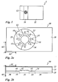
- Fig.1 shows a security document 1.
- the security document 1 is preferably a value document, such as a banknote. However, it is also possible that the security document 1 is an ID document, a credit card or the like.
- the document of value 1 has a carrier substrate 11 and a security element 10 applied in the form of a multilayer film body or applied to the carrier substrate 11 or integrated into the carrier substrate 11.
- the security element 10 preferably has a strip-shaped shape with a width between 1 mm and 20 mm, more preferably between 2 mm and 10 mm. Furthermore, the security element 10 preferably extends over the entire width of the carrier substrate 11, as shown by way of example in FIG Fig.1 is shown.
- the security element 10 has one or more optical security features, of which in Fig.1 a security feature 12 is shown.
- a security feature 12 is shown.
- one or more further, in particular visually recognizable security features can thus also be provided on the security element 10.
- the substrate 11 of the value document 1 it is also possible for the substrate 11 of the value document 1 to have one or more transparent regions or corresponding window-shaped recesses in the region of the security element 10, in the region of which the security element 10 exhibits a security feature visible in transmission.
- a transparent region of the carrier substrate 11 or such a window-shaped recess in the carrier substrate 11 is provided in the region of the security feature 12.
- the carrier substrate 11 preferably consists of a paper substrate.
- the carrier substrate 11 consists of a plastic substrate or a multilayer substrate, which consists of several layers selected from the group of plastic layers, metal layers, fiber layers and paper layers.
- the security document 1 in addition to the security element 10 has further security elements and that the security element 10 is at least partially overprinted with one or more layers, for example, is partially overprinted with a security printing.
- the security element 10 has a different shape, for example, in the form of a patch is formed, and that the security document 1 another than in Fig.1 has shown shape, for example in the form of a card, a passport, etc. is formed.
- Fig. 2a and Fig. 2b illustrate the basic structure of the security element 10 with reference to a section of the security element 10 in the area of the security feature 12.
- the security element 10 has a protective layer 22, a transparent layer 23 and an adhesive layer 25.
- the layer 24 preferably consists of a transparent, semi-transparent or opaque reflection layer or a transparent, semi-transparent or opaque thin-film layer system.
- the protective layer 22 preferably consists of a protective lacquer layer of a layer thickness between 0.5 ⁇ m and 20 ⁇ m.
- the transparent layer 23 preferably consists of a replication lacquer layer with a layer thickness between 1 ⁇ m and 50 ⁇ m, more preferably between 2 ⁇ m and 20 ⁇ m.
- the adhesive layer 25 is preferably a layer of a thermally activatable adhesive with a layer thickness between 1 ⁇ m and 5 ⁇ m. It is also advantageous to use as adhesive for the adhesive layer 25 a UV2011ierbaren adhesive.
- Fig. 2a and Fig. 2b is indicated by the upper surface of the layer 23 defined by coordinate axes x and y ground plane and further defined on this ground plane perpendicular z-axis.
- Fig. 2a and Figure 2d exemplify a defined by the layer 23 three-dimensional coordinate system with an x-axis, a y-axis and a z-axis, which defines corresponding spatial directions 61, 62 and 63. It is also possible here that relief structures are also molded into the upper surface of the layer 23 and thus the upper surface of the layer 23 is not completely flat. In this case, the ground plane is defined by the plan areas of the upper surface of the layer 23.
- the security feature 12 is composed of several areas 31, 32, 33, 34 and 35, each of which has a different visual appearance.
- the regions 31 to 35 are further surrounded by a region 30, which preferably does not have an optically variable appearance shows.
- the region 30 may in particular have a matt structure or an anti-reflection structure.
- a multiplicity of facet surfaces which form a relief structure 41 in the region 31, are molded into the lower surface of the layer 23.
- regions 32 in which a multiplicity of facet surfaces are likewise molded into the lower surface of the layer 23.
- different diffractive relief structures are respectively molded into the lower surface of the layer 23, a diffractive relief structure 42 being formed here in the region 33 and a diffractive relief structure 43 being formed in the region 35.
- a background structure is molded into the first layer.
- Fig. 2c and Fig. 2d exemplify an embodiment in which the area 31 on the one hand a plurality of partial areas 311, which are each covered with a facet surface 50, and further comprises a portion 312, which is covered with a background structure 44.
- the partial region 312 is preferably formed as a background region relative to the facet surfaces 50.
- background texture 44 in the portion 312 has a relief structure in the layer 23 is preferably molded, the motion and / or morphing effects generated as a second optical effect (such as a Kinegram ®).
- a second optical effect such as a Kinegram ®
- Such motion or morphing effects are eg in EP 0 375 833 A1 and EP 0 105 099 A1 and with regard to the formation of the background structure 44, reference is made to these documents.
- the portion 312 is divided into a plurality of zones 322.
- a preferably linear diffraction grating is shaped, wherein the diffraction gratings of adjacent zones 322 preferably differ in at least one grating parameter, in particular in their azimuth angle or their spatial frequency.
- the grid parameters are preferably not varied.
- the orientation of the grids or also other grating parameters or combinations of grating parameters of adjacent zones 322 can be varied.
- the second optical effect of the background structure 44 and the first optical effect of the facet surfaces 50 may complement each other. For example, it is possible to produce a "rolling bar" effect with the facet surfaces 50 and to generate an opposing movement effect with the background structure 44. Since the feature sizes of the facet faces 50 and the area areas arranged therebetween, which are covered by the background structure, are below the resolution of the unaided eye, the two optical effects produce a common optical effect from the superposition of the two individual effects. This makes it possible to produce particularly characteristic optical effects here.
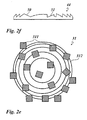
- Fig. 2e and Fig. 2f illustrates a further embodiment, in which in the partial areas of the first area, which are not occupied by the facet surfaces, in the first layer of a relief structure with structures, such as those in EP 1 562 758 B1 are described, are provided.
- the regions 311, in each of which a facet surface 50 is preferably provided, are thus preferably surrounded by a background region 312 into which such a background structure 44 is molded.
- the background structure generates a so-called "surface relief” effect, i. it produces lens-like, diffractive and / or refractive microscopic surface structures that simulate a macroscopic three-dimensionality similar to a refractive distortion lens or optically distorting free-form surface. This makes it possible to produce seemingly three-dimensional structures, e.g. Ornaments, symbols, alphanumeric symbols.
- the area occupation by the facet surfaces should be rather low, which typically should be less than 70%, preferably less than 50% and particularly preferably less than 30%.
- the facet surfaces 50 add a glittering effect to the "surface relief" effect.
- the facet faces 50 are provided with color or color effect generating structures, such facets even add colored or color changing glitter effects to the "surface relief” effect.
- Another variant combines the function F SR (x, y) of the surface relief effect with the function F (x, y) of the facet faces 50.
- the effects of the surface relief structures and the facet faces 50 can complement one another. For example, it is possible with the "surface relief" effect to produce a convex lens function and with the facet surfaces 50 a concave-acting motion function.
- the relief structures 41, 42 and 43 or the background structure 44 are here preferably formed in one and the same manufacturing process, for example by means of an embossing tool in the layer 23, which has a surface on which the three-dimensional negative mold or complementary shape of these relief structures is provided.
- the layer 23 may thus consist, for example, of a thermoplastic replication lacquer layer, and the replication tool used is an embossing tool shaped as described above. Using heat and pressure, the relief structures 41, 42 and 43 or the background structure 44 are molded into the lower surface of the layer 23 in the same manufacturing process using heat and pressure.
- the layer 23 may consist of a UV-crosslinkable replication lacquer and the relief structures 41, 42 and 43 or the background structure 44 to be UV-irradiated into the lower surface of the replication lacquer layer by means of the replication tool and simultaneous and / or subsequent UV irradiation Replication is molded.
- the shaping of the relief structures 41, 42 and 43 or the background structure 44 preferably takes place by means of one and the same replication tool.
- the relief structures 41, 42 and 43 or the background structure 44 are register-accurate, ie, positionally accurate in the x- and / or y-direction relative to one another in the layer 23 are formed and so register fluctuations, ie tolerances in the relative position to each other, can be avoided, which occur by the introduction of the relief structures 41, 42 and 43 and the background structure 44 by means of different replicating tools and successive manufacturing processes.
- Fig. 3a and 3b exemplify a possible manufacturing process for the production of the security element 10.
- the carrier film 20 is preferably a plastic film with a layer thickness between 6 ⁇ m and 300 ⁇ m.
- the plastic film here preferably consists of PET or BOPP.
- the release layer 21 preferably has a layer thickness between 0.1 ⁇ m and 0.5 ⁇ m and preferably has wax components. However, it is also possible to dispense with the release layer 21.
- the layer 23 is applied to the protective layer 22 and at the same time or in a subsequent step in the regions 31 to 35 the associated relief structures, for example the relief structures 41, 42 and 43 or the background structure 44 in the exposed surface the layer 23 is molded. In the area 30, preferably no relief structure is molded into the exposed surface of the layer 23.
- Fig. 3a shows an example of a section of the area 31, in which the relief structures 41 is molded into the layer 23.
- a plurality of facet surfaces are molded into the exposed surface 232 of the layer 23.
- Each of the facet faces has a smallest dimension of more than 1 ⁇ m and a largest dimension of less than 300 ⁇ m, ie a width of more than 1 ⁇ m and a length of less than 300 ⁇ m.
- the smallest dimensions of the facet surfaces are between 1 ⁇ m and 20 ⁇ m, particularly preferably between 1 ⁇ m and 10 ⁇ m, and the largest dimension of the facet surfaces is between 5 ⁇ m and 100 ⁇ m, preferably between 5 ⁇ m and 50 ⁇ m and particularly preferably between 5 ⁇ m and 30 ⁇ m.
- the region 31 has only one facet surface 50, which is surrounded by the background structure 44, as shown in FIGS Figures 2d and 2f is shown.
- the facet surfaces 50 of the embodiments according to Fig. 2c to Fig. 2g are preferably as based on the Fig. 3a to Fig. 10c described molded and arranged so that reference is made in this regard to these statements.
- Fig. 3c shows a section of a further variant in which in the layer 23, a relief structure 41 'is molded.
- the relief structure 41 ' has facet surfaces 50 with a structural height H f of less than 2 ⁇ m.
- H f structural height
- the dimension of the facet faces is pseudorandomly varied in the direction of the largest slope of the facet faces, the parameter variation value being selected from a pseudorandom group of only three parameter variation values.
- Each of the facet faces 50 is defined by the parameters F Facet area, area size S of the facet area, spacing H of the centroid of the facet faces from the ground plane, position P of the centroid of the facet face in the coordinate system chucked by the x-axis and the y-axis, inclination angle Ax of the facet face about the x-axis against the ground plane , Inclination angle Ay of the facet face about the y-axis against the base plane and azimuth angle Az of the facet face defined by the rotation angle of the facet face about the z-axis.
- one or more of the parameters F, S, H, P, Ax, Ay and Az of the facet faces 50 arranged in this region are varied pseudo-randomly within a variation range predefined for the region 31.
- One or more of the aforementioned parameters are thus pseudorandomly varied in each of the facet faces 50 arranged in the region 31.
- a plurality of facet surfaces 50 are formed in the surface 232 of the layer 23 and one or more of the parameters F, S, H, P, Ax, Ay, Az are pseudo - varies randomly. It is particularly advantageous in this case if the parameters F, S, H, P, Ax, Ay, Az are also predefined by a predefined function in the second area and these predefined parameters are then superimposed additively with the pseudorandom variation of one or more of these parameters becomes. In this case, it is advantageous if the predefined function of the area 31 differs from the predefined function of the areas 32, thereby causing different optical variable effects to be generated in the areas 31 or 32.
- the parameters which are pseudo-randomly varied in the region 31 on the one hand and in the region 32 on the other hand differ.
- the facet areas may be arranged in area 31 by means of a function in the form of a convex lens and in area 32 by means of a flat function or by means of a function in the form of a concave lens.
- at least one of the variation ranges of the varied parameters in the region 31 and in the region 32 is selected differently and in this case the different variation regions differ in particular by at least 20%, more preferably at least 50%. This also makes an interesting, different visual appearance of the areas 31 and 32 achievable.
- diffractive relief structures or isotropic or anisotropic matt structures are formed in the surface 232 of the layer 23, which each exhibit a different optically variable effect.
- the replicated in these areas relief structures are formed, for example, of diffraction gratings with a spatial frequency of between 700 lines / mm to 5000 lines / mm, computer-generated holograms, 2D or 3D holograms, or a Kinegram ®.
- the zero-order diffraction structure is preferably a relief structure with a spacing of the individual structural elements in the range of light wavelengths to half the wavelength of light for a wavelength in the visible wavelength range (about 350 nm to 800 nm), which preferably comprises a high-index dielectric reflection layer (HRI layer) ) is provided for generating a typical viewing angle-dependent color effect upon tilting and / or rotation of the security element.
- HRI layer high-index dielectric reflection layer
- the layer 24 is applied to the surface 232.
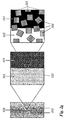
- the layer 24 here preferably comprises a thin-film layer system, as shown in FIG Fig. 3b is shown.
- the layer 24 thus has, for example, a semi-transparent absorption layer 241, a spacer layer 242 and a metallic reflection layer 243.
- the absorption layer 241 is preferably a very thin and thus semitransparent metal layer, for example a layer of chromium with a layer thickness of 5 nm.
- the spacer layer 242 is a layer of a transparent dielectric, for example MgF 2 , SiO 2 or polymer.
- the layer thickness of the spacer layer 242 here is preferably selected such that it has the ⁇ / 2 or ⁇ / 4 for a defined viewing angle.
- the optical thickness of the layer 242 is in the range of half or quarter wavelengths of light and thus in the interference of the interface between the absorption layer 241 and the spacer layer 242 on the one hand and the interface between
- the distance layer 242 and the reflection layer 243 reflect a light-angle-dependent color shift effect in the region of the light visible to the human eye.
- the layer 243 is preferably a substantially opaque metal layer, for example a layer of aluminum with a layer thickness of 30 nm.
- HRI high refraction index
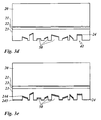
- the reflection layer 24 is not applied over the entire surface of the entire surface 232 of the layer 23, but only partially and / or pattern-wise applied to the layer 232. For example, it is possible to apply the layer 24 only in the areas 31 to 35 and not in the surrounding area 30.
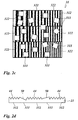
- the layer 24 is also not patterned in the areas 31 to 34 over the entire surface, but in pattern form, so as to code, for example, information visible in transmission.
- Fig. 3d shows an example in which in the area 31 only in the areas of the area 31 occupied by the facet surfaces 50 a metallic reflection layer, eg of aluminum or copper, is provided as layer 24, but not in the subregions of the area not occupied by the facet areas 31 is provided.
- a metallic reflection layer eg of aluminum or copper
- different layers 24 to be applied to the surface 232 of the layer 23 in the regions 31, 32, 33, 34 and / or 35, for example, in the region 31 a thin-film layer system is applied the areas 32 a metallic reflection layer is applied and in the areas 33 to 35 an HRI layer is applied as a reflection layer.
- a metallic reflection layer for example aluminum
- another metallic reflection layer for example copper
- the layer 24 may have partial regions in the region 31 and / or in the region 32 in which the layer 24 has a different structure, or is formed by different layers or different combinations of layers.
- Fig. 3e shows an example in which in areas 31 and 32 only on the facet surfaces 50, a metallic reflection layer 244, for example aluminum, is provided. Further, on the entire surface of the multi-layer body, ie in the areas 31, 32 and 33, 34 and 35 and in particular also on the facet surfaces 50 and adjacent to the facet surfaces 50, an additional further, preferably transparent or translucent reflection layer 245 applied, for example from an HRI material such as ZnS or TiO 2 .
- an HRI material such as ZnS or TiO 2 .
- a reflective layer 24 may be applied within the regions 31 and 32, which is structured differently in partial regions of the regions 31 and 32, or for the surface areas 232 and 23 only to surround the surfaces of the surfaces 232 and 23 instead of the facet surfaces reflective layer 24 are provided.
- the transfer film is after Fig. 3b applied to the carrier substrate 10, the adhesive layer 25 activated, for example, by heat and pressure and then peeled off the carrier film 20, so that a multi-layer body with the in Fig. 2b remains shown layer structure on the carrier substrate 11 remains.
- the security element 10 in addition to the in Fig. 2b 1 or more further decorative layers, reflection layers, layers of a magnetic material, etc.
- the security element 10 is formed as a laminating film and instead of the protective layer 22, a carrier film is provided , which is preferably connected to the layer 23 with an adhesion-promoting layer.
- FIG Fig. 2g explains: as in Fig. 2g shown schematically, the facet surfaces 50, a first optical effect, eg "rolling bar” effect produced and this combined with a surface area demetallization of a portion 312 of the first area without facet faces 50 for local removal of the particular metallic and opaque reflection layer (in the form of Number "50").
- a first optical effect eg "rolling bar” effect produced and this combined with a surface area demetallization of a portion 312 of the first area without facet faces 50 for local removal of the particular metallic and opaque reflection layer (in the form of Number "50").
- the region 31 thus has a multiplicity of partial regions 311 which are each formed by the surface occupied by a facet surface and which are covered with a reflection layer, preferably a metallic reflection layer.
- a reflection layer preferably a metallic reflection layer.
- the first portion 313 is also covered with the reflection layer, in particular covered with the metallic reflection layer.
- the second portion 312 is not covered with the reflective layer, preferably demetallized.
- the partial regions 311 are thus surrounded by the partial regions 312 and surrounded by the partial region 313 outside the "50".
- such a multilayer body has a first optical effect 351 in reflection and a second optical effect 352 in transmission.
- the "rolling bar” effect appears as the first optical effect with full intensity over the entire area, since all facet areas are provided with the reflection layer.
- the number "50” appears as the second optical effect 352, since the metallic reflection layer removed in some regions acts as a shadow mask.
- the demetallization for removing the metallic reflection layer can in this case take place, for example, with the aid of the demetallization structures described above or by means of known etching processes or washing processes for the local removal of metal layers.
- a “rolling bar” effect is an optical effect similar to a reflective cylindrical lens.
- the areas of the cylindrical lens which reflect the light in the direction of an observer appear brighter than the areas which reflect the light in other directions.
- this function produces a kind of "band of light” which apparently passes over the cylindrical lens when the multi-layer body is tilted in the direction of the viewing angle.
- the facet areas each have a width 67 and a length 68, wherein width generally refers to the smallest dimension of two opposite edge points of a facet surface and the length to the largest dimension between two ridge points of a facet surface.
- the facet surfaces may have any shape, for example, the shape of a square, a rectangle, a regular polygon, a random polygon, a circular disk or a conic. Particularly advantageous here is the use of facet surfaces with a circular disk-shaped or conically shaped form F has proven.
- the shape of the facet surfaces 50 is advantageous to use as a hidden security feature. It is thus possible, for example, to select the facet surfaces 50 in the form of letters or symbols, for example the outline of a country, of a characteristic mountain or lake, or combinations or superimpositions thereof.
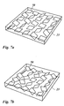
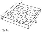
- the surface of the facet surface 50 is in the in Fig. 4 embodiment shown preferably formed flat.
- the facet surfaces 50 all have the same shape F and area size S.
- the area size S and / or shape F of the facet faces 50 may vary in the region 31, for example to be randomly varied or to differ from facet face to facet face according to the predefined function, such as by special variation of the face size S Information, for example, to generate a grayscale image.
- the variation range of the random displacement in the x-direction is preferably chosen between -Dx / 2 and + Dx / 2 and the variation range of the random displacement in the y-direction between -Dy / 2 and + Dy / 2, where Dx the Dimension 68 of the facet surface 50 in the x-direction and Dy is the dimension 67 of the facet surface in the direction of the y-axis.
- Fig. 7D shows an embodiment in which the azimuth angle Az of the facet surfaces 50 varies pseudo-randomly.
- the range of variation of the azimuth angle Az is hereby preferably selected between -45 ° and + 45 °.
- Fig. 7e shows an embodiment in which the parameters P, Ax, Ay and Az are pseudorandomly varied in the illustrated range.
- a function F (x, y) is predefined, which contains a predefined optical information, in particular a predefined optically variable information.
- a function F (x, y) is predefined, which contains a predefined optical information, in particular a predefined optically variable information.
- the azimuth angle Az, the spacing H of the centroid of the base plane, and the area size S of the respective facet surfaces and optionally also the shape F of the facet surfaces can optionally be determined individually by the function F (x, y).
- the spacing H can thus be determined, for example, from the spacing of the respective point from a reference surface (possibly also with additional linkage with a modulo function) and the area size S by a brightness value assigned to the respective point.
- the position of the respective facet surfaces is optionally pseudorandomly varied as set forth above, and then the corresponding calculations for the subsequent facet surface 50 are performed.
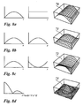
- FIG. 8a to Fig. 8e illustrate now exemplified several such predefined functions F (x, y), under such a function, as the example of the FIG. 8d is shown, a function defined according to a cylindrical coordinate system is to be understood.
- the basis Fig. 8a clarified function F (x, y) generates an optical "rolling bar" effect similar to a reflective cylindrical lens.
- the areas of the cylindrical lens which reflect the light in the direction of an observer appear brighter than the areas which reflect the light in other directions.
- this function produces a kind of "band of light” which apparently passes over the cylindrical lens when the multi-layer body is tilted in the direction of the viewing angle.
- the basis Fig. 8b clarified function F (x, y) generates a visually variable effect similar to a reflective spherical lens.
- the basis Fig. 8c clarified function F (x, y) generates a distortion effect resulting from the convex and concave reflecting surfaces.
- function F (x, y) generates a radial expansion-movement effect.
- the function F (x, y) thus preferably describes the shape of a three-dimensional freeform surface, for example the one in the figures Fig. 8a to Fig. 8e
- the inclination angles Ax and / or Ay are determined by the respective surface normal of this three-dimensional freeform surface in the centroid of the respective facet surface.
- the function F (x, y) is a logo, a picture, a is based on an alphanumeric character, a geometric figure or another object or the function F (x, y) describes the section of a surface of a three-dimensional object.
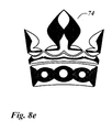
- Fig. 8e shows the representation of a free-form surface determined by a predefined function F (x, y) in the form of a three-dimensionally shaped crown.
- the three-dimensional free-form surface can preferably also be defined by taking a given two-dimensional logo, image or letter as a starting point and rising in a lens-like manner from the contours of such a two-dimensional object, i. similar to the curvature of a continuously curved optical lens, a free-form surface is defined for the respective centroid, which preferably follows the outline of the two-dimensional initial object and - due to the lens-like elevation - shows a lens-like magnification, reduction or distortion effect.
- This is also achieved, for example, by providing a three-dimensional surface providing a lens function, e.g. the area 71 is geometrically transformed according to the two-dimensional contour lines.
- the freeform surface as shown in the figures Fig. 8a - Fig. 8d is formed by a continuous and differentiable function and is composed of flat and curved surface areas.
- the maxima of the free-form surface in the z-axis direction are preferably between 4 mm and 40 mm, more preferably between 8 mm and 20 mm, with respect to their respective projection onto the ground plane.
- the free-form surface may in this case comprise one or more free-form elements, which, for example, have each been determined as outlined above from a two-dimensional object or the scanning of a section of a surface of a three-dimensional object.
- the smallest dimension of each of these freeform elements is preferably between 2mm and 40mm, more preferably between 4mm and 20mm.
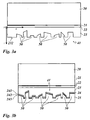
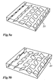
- Fig. 9a to Fig. 9d illustrate the implementation of the steps for determining the parameters of the facet surfaces 50 on the basis of a predefined function F (x, y), which a parabolic freeform surface according to Fig. 8a describes that generates a "rolling bar" effect as optically variable information (with appropriate design of the free-form surface with reflective layer for reflection in reflection / reflected light).
- the facet faces 50 are positioned with in their respective control position and the inclination angles Ax and Ay of the respective facet surfaces corresponding to the surface normal of the three-dimensional freeform surfaces described by the function F (x, y) in the respective centroid of the facet faces 50 are determined in Fig. 9a is shown.
- the inclination angle Ay is superimposed with a pseudo-random variation of the inclination angle Ay, as shown in FIG Fig. 9b is shown.
- the range of variation of this pseudorandom variation is hereby preferably chosen between 20% and 80% of the mean slope of the function F (x, y).
- the position P of the facet faces is pseudorandomly varied by a pseudorandom shift from the respective control position, as shown in FIG Fig. 9d is shown.
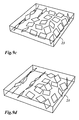
- Fig. 10a to Fig. 10c show photographs of the area 31 from different viewing angles, with a corresponding choice of the function F (x, y) as a spherical lens according to FIG Fig. 8b ,
- the embodiments presented above have a fill factor, a ratio of the facet-covered area of area 31 to the total area of area 32, which is between 80% and 50%.
- the optically variable impression is advantageously superimposed by a visual impression in a certain viewing area, which is formed by the areas of the area 31 not covered with facet surfaces.
- the spacing of the facet faces relative to one another can be reduced or a superimposition of facet faces can be permitted.
- the grid width of the grid between 0.8 times and 1.5 times the dimension of the facet faces in the respective direction is preferably selected for this purpose.
- Diffractive structures for example sinusoidal, rectangular or sawtooth-shaped gratings.
- the grids can be linear, crossed or hexagonal.
- these diffractive structures have grating periods in the range of 200 nm to 2000 nm.
- the texture depth is preferably in the range of 20nm to 2000nm.
- these diffraction gratings can be provided over the entire surface on the respective facet surface.
- the grid lines of all facet surfaces can be aligned parallel to each other, regardless of the orientation of the facet surfaces.
- the azimuth angle of the diffractive gratings is oriented in the direction of the azimuth angle of the respective facet surface 50.
- diffractive structures such as a diffractive line grating of 500 to 5000 lines / mm in particular, may serve to align the molecules of a liquid crystal layer on the diffractive structure to adjust the polarization properties of the liquid crystal material.
- Moth eye structures reduce the reflection at the interface between the facets and the surrounding medium.
- structures which produce this effect for example linear sub-wavelength gratings with a period of preferably ⁇ 200 nm. All these types of structures can be used to adjust the brightness of the area with the facet structures. It is also conceivable to mix or combine 31 facet surfaces with moth-eye structures with facet surfaces without structures or with other structures.
- Diffraction structures of zeroth order as for example in the US 4,484,797 and the WO 03/059643 A1 are described. These structures typically have grating periods in the range of 200nm to 500nm and grating depths between 50nm and 300nm.
- the grid profile may be rectangular or sinusoidal or more complex.
- These structures are preferably with an HRI layer or a multilayer packet of HRI and LRI layers coated.
- the layer thickness of the individual HRI layers is typically in the range of 30 nm to 300 nm. If the zero-order diffraction structures have a preferred direction, for example linear or crossed, they have a color shift effect when rotated. For example, the combination of these types of structures with the facet surfaces makes it possible to mimic optical effects produced by pigments with zero-order diffraction structures.
- the application of our invention makes it possible to avoid the laborious detour via the production, application and optionally alignment of such pigments.
- linear grating lines of the zero order diffraction structures are perpendicular to the axis of a rolling bar as in FIG Fig. 8a sketched, ie aligned in the x direction.
- the zeroth-order diffraction patterns exhibit a small color-shift effect, as known for viewing parallel to the grid lines.
- the rolling bar effect dominates.
- the color-turning effect of the zeroth-order diffraction structures dominates.
- the zeroth-order diffraction patterns show a pronounced color-shift effect.
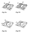
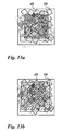
- Nanotext as in the figures Figure 12 a and 12b is shown. Again, the nanotext can be like this in Figures 12a is shown as being independent of the orientation of the facet faces 50 or corresponding to the azimuth angle of the respective facet face 50, as shown in FIG Fig. 12b is shown. Under nanotext are also nanomotives like logos, Outline maps, symbols, images, encodings, barcodes and the like.
- Such structures can also overlay the facet surfaces 50 only in a predetermined area, as in FIG Fig. 13a is shown.
- the line-like structures 48 covered with a diffraction grating overlay the facet surfaces 50 in a partial region.
- FIG. 5 shows a corresponding embodiment in which the facet surfaces 50 are superimposed by a zero-order diffraction structure 49 and thus generated in the corresponding region of the color changes generated by these structures, for example from red to green during a 90 ° rotation of the multilayer body.
Landscapes
- Engineering & Computer Science (AREA)
- Manufacturing & Machinery (AREA)
- Business, Economics & Management (AREA)
- Accounting & Taxation (AREA)
- Finance (AREA)
- Physics & Mathematics (AREA)
- Ophthalmology & Optometry (AREA)
- Mechanical Engineering (AREA)
- Health & Medical Sciences (AREA)
- General Physics & Mathematics (AREA)
- Optics & Photonics (AREA)
- Diffracting Gratings Or Hologram Optical Elements (AREA)
- Optical Elements Other Than Lenses (AREA)
- Credit Cards Or The Like (AREA)
- Laminated Bodies (AREA)
- Measuring Fluid Pressure (AREA)
Applications Claiming Priority (2)
| Application Number | Priority Date | Filing Date | Title |
|---|---|---|---|
| DE102011014114A DE102011014114B3 (de) | 2011-03-15 | 2011-03-15 | Mehrschichtkörper und Verfahren zur Herstellung eines Mehrschichtkörpers |
| PCT/EP2012/053873 WO2012123303A1 (de) | 2011-03-15 | 2012-03-07 | Mehrschichtkörper |
Publications (2)
| Publication Number | Publication Date |
|---|---|
| EP2686172A1 EP2686172A1 (de) | 2014-01-22 |
| EP2686172B1 true EP2686172B1 (de) | 2015-06-24 |
Family
ID=45841464
Family Applications (1)
| Application Number | Title | Priority Date | Filing Date |
|---|---|---|---|
| EP12709049.6A Active EP2686172B1 (de) | 2011-03-15 | 2012-03-07 | Mehrschichtkörper |
Country Status (13)
Cited By (2)
| Publication number | Priority date | Publication date | Assignee | Title |
|---|---|---|---|---|
| EP3337675B1 (de) | 2015-08-17 | 2019-11-13 | Giesecke+Devrient Currency Technology GmbH | Sicherheitselement, verfahren zum herstellen desselben und mit dem sicherheitselement ausgestatteter datenträger |
| DE102021106085A1 (de) | 2021-03-12 | 2022-09-15 | Leonhard Kurz Stiftung & Co. Kg | Transferfolie, ein Verfahren zur Herstellung einer Transferfolie und ein Verfahren zur Herstellung eines mit einer Transferfolie dekorierten Kunststoffartikels |
Families Citing this family (40)
| Publication number | Priority date | Publication date | Assignee | Title |
|---|---|---|---|---|
| DE102010047250A1 (de) * | 2009-12-04 | 2011-06-09 | Giesecke & Devrient Gmbh | Sicherheitselement, Wertdokument mit einem solchen Sicherheitselement sowie Herstellungsverfahren eines Sicherheitselementes |
| DE102012105571B4 (de) | 2012-06-26 | 2017-03-09 | Ovd Kinegram Ag | Dekorelement sowie Sicherheitsdokument mit einem Dekorelement |
| DE102012020550A1 (de) * | 2012-10-19 | 2014-04-24 | Giesecke & Devrient Gmbh | Optisch variables Flächenmuster |
| DE102013007998A1 (de) * | 2013-05-08 | 2014-11-13 | Giesecke & Devrient Gmbh | Wertdokumentsubstrat, Wertdokument und Verfahren zum Herstellen eines Wertdokuments |
| FR3019496A1 (fr) * | 2014-04-07 | 2015-10-09 | Hologram Ind | Composant optique de securite a effet reflectif, fabrication d'un tel composant et document securise equipe d'un tel composant |
| DE102014014082A1 (de) * | 2014-09-23 | 2016-03-24 | Giesecke & Devrient Gmbh | Optisch variables Sicherheitselement mit reflektivem Flächenbereich |
| DE102014014079A1 (de) * | 2014-09-23 | 2016-03-24 | Giesecke & Devrient Gmbh | Optisch variables Sicherheitselement mit reflektivem Flächenbereich |
| CN104385800B (zh) | 2014-10-16 | 2017-10-24 | 中钞特种防伪科技有限公司 | 光学防伪元件及光学防伪产品 |
| US10859851B2 (en) | 2014-10-24 | 2020-12-08 | Wavefront Technology, Inc. | Optical products, masters for fabricating optical products, and methods for manufacturing masters and optical products |
| DE102014118366A1 (de) * | 2014-12-10 | 2016-06-16 | Ovd Kinegram Ag | Mehrschichtkörper und Verfahren zu dessen Herstellung |
| DE102015100280A1 (de) * | 2015-01-09 | 2016-07-14 | Ovd Kinegram Ag | Verfahren zur Herstellung von Sicherheitselementen sowie Sicherheitselemente |
| DE102015100520A1 (de) | 2015-01-14 | 2016-07-28 | Leonhard Kurz Stiftung & Co. Kg | Mehrschichtkörper und Verfahren zu dessen Herstellung |
| DE102015005911A1 (de) | 2015-05-07 | 2016-11-10 | Giesecke & Devrient Gmbh | Optisch variables Sicherheitselement |
| DE102015005969A1 (de) | 2015-05-08 | 2016-11-10 | Giesecke & Devrient Gmbh | Optisch variables Sicherheitselement |
| JPWO2016194385A1 (ja) * | 2015-06-02 | 2018-06-07 | 凸版印刷株式会社 | 積層体およびその製造方法 |
| KR102630381B1 (ko) * | 2015-07-13 | 2024-01-29 | 웨이브프론트 테크놀로지, 인코퍼레이티드 | 광학 제품, 광학 제품을 제작하기 위한 마스터, 그리고 마스터 및 광학 제품을 제조하기 위한 방법 |
| GB2545387A (en) * | 2015-07-24 | 2017-06-21 | De La Rue Int Ltd | Security device and method of manufacturing thereof |
| GB201513096D0 (en) * | 2015-07-24 | 2015-09-09 | Rue De Int Ltd | Diffractive security device and method of manufacturing thereof |
| KR102380813B1 (ko) | 2016-04-22 | 2022-03-30 | 웨이브프론트 테크놀로지, 인코퍼레이티드 | 광 스위치 장치 |
| EP3254862B3 (de) * | 2016-06-08 | 2020-04-29 | Fraunhofer-Gesellschaft zur Förderung der angewandten Forschung e.V. | Verfahren zur identifikation für produkte |
| DE102016215160A1 (de) | 2016-06-08 | 2017-12-14 | Fraunhofer-Gesellschaft zur Förderung der angewandten Forschung e.V. | Kennzeichnungselement für Produkte |
| CN106022452A (zh) * | 2016-06-20 | 2016-10-12 | 深圳市华正联实业有限公司 | 一种防伪方法 |
| JP6946632B2 (ja) * | 2016-10-24 | 2021-10-06 | 大日本印刷株式会社 | 回折光学素子、回折光学素子及び保持具のセット部材、光照射装置 |
| CN108318945B (zh) * | 2017-01-18 | 2020-05-19 | 昇印光电(昆山)股份有限公司 | 光学膜及制造该光学膜的模具 |
| DE102017106433A1 (de) | 2017-03-24 | 2018-09-27 | Ovd Kinegram Ag | Sicherheitselement und Verfahren zur Herstellung eines Sicherheitselements |
| JP6879002B2 (ja) | 2017-03-29 | 2021-06-02 | 凸版印刷株式会社 | 表示体 |
| DE102017004065A1 (de) * | 2017-04-27 | 2018-10-31 | Giesecke+Devrient Currency Technology Gmbh | Verfahren zur Herstellung eines Sicherheitselements |
| WO2018208751A1 (en) * | 2017-05-08 | 2018-11-15 | Physna Llc | System and methods for 3d model evaluation |
| DE102017006421A1 (de) * | 2017-07-07 | 2019-01-10 | Giesecke+Devrient Currency Technology Gmbh | Optisch variable Sicherheitsanordnung |
| EP4020021B1 (en) | 2017-07-28 | 2024-08-07 | Toppan Printing Co., Ltd. | Reflection suppression segment, display, and method for verifying display |
| EP3655253A4 (en) | 2017-10-20 | 2021-04-28 | Wavefront Technology, Inc. | OPTICAL SWITCHING DEVICES |
| KR102035907B1 (ko) * | 2017-12-15 | 2019-10-23 | 주식회사 엘지화학 | 장식 부재 및 이의 제조방법 |
| GB2572745B (en) * | 2018-03-22 | 2021-06-09 | De La Rue Int Ltd | Security elements and methods of manufacture thereof |
| CN108919688B (zh) * | 2018-08-14 | 2020-09-22 | 南京工大数控科技有限公司 | 一种离散式测控在线执行方法 |
| EP3778256B1 (de) | 2019-08-12 | 2025-01-15 | Hueck Folien Gesellschaft m.b.H. | Sicherheitselement |
| CN112848742A (zh) * | 2019-11-27 | 2021-05-28 | 中钞特种防伪科技有限公司 | 光学防伪元件及光学防伪产品 |
| CA3195189A1 (en) | 2020-10-07 | 2022-04-14 | Christopher Chapman Rich | Optical products, masters for fabricating optical products, and methods for manufacturing masters and optical products |
| EP4217792A4 (en) | 2020-10-07 | 2024-10-30 | Wavefront Technology, Inc. | OPTICAL PRODUCTS, MATRICES FOR THE MANUFACTURE OF OPTICAL PRODUCTS AND METHODS FOR THE MANUFACTURE OF MATRICES AND OPTICAL PRODUCTS |
| DE102021002471A1 (de) * | 2021-05-10 | 2022-11-10 | Giesecke+Devrient Currency Technology Gmbh | Sicherheitselement mit Volumenhologramm und zusätzlichen Effekten |
| US12166520B2 (en) * | 2021-10-22 | 2024-12-10 | Case-Mate, Inc. | Case with illusory design elements |
Family Cites Families (23)
| Publication number | Priority date | Publication date | Assignee | Title |
|---|---|---|---|---|
| US4484797A (en) * | 1981-07-20 | 1984-11-27 | Rca Corporation | Diffractive subtractive color filter responsive to angle of incidence of polychromatic illuminating light |
| CH659433A5 (de) | 1982-10-04 | 1987-01-30 | Landis & Gyr Ag | Dokument mit einem beugungsoptischen sicherheitselement. |
| EP0360969B1 (de) | 1988-09-30 | 1993-12-15 | Landis & Gyr Business Support AG | Beugungselement |
| EP0375833B1 (de) * | 1988-12-12 | 1993-02-10 | Landis & Gyr Technology Innovation AG | Optisch variables Flächenmuster |
| US5105306A (en) | 1989-01-18 | 1992-04-14 | Ohala John J | Visual effect created by an array of reflective facets with controlled slopes |
| CA2060057C (en) | 1991-01-29 | 1997-12-16 | Susumu Takahashi | Display having diffraction grating pattern |
| DE69607857T2 (de) | 1995-11-28 | 2000-08-17 | Ovd Kinegram Ag, Zug | Optisch variables flächenmuster |
| AU738289B2 (en) | 1997-12-09 | 2001-09-13 | Commonwealth Scientific And Industrial Research Organisation | A diffractive device with three-dimensional effects |
| US7517578B2 (en) | 2002-07-15 | 2009-04-14 | Jds Uniphase Corporation | Method and apparatus for orienting magnetic flakes |
| AUPR483301A0 (en) | 2001-05-08 | 2001-05-31 | Commonwealth Scientific And Industrial Research Organisation | An optical device and methods of manufacture |
| DE50212303D1 (de) | 2002-01-18 | 2008-07-03 | Ovd Kinegram Ag | Diffraktives sicherheitselement mit integriertem optischen wellenleiter |
| DE10221491A1 (de) * | 2002-05-14 | 2003-12-04 | Kurz Leonhard Fa | Optisch variables Flächenmuster |
| DE10254500B4 (de) | 2002-11-22 | 2006-03-16 | Ovd Kinegram Ag | Optisch variables Element und dessen Verwendung |
| DE10351129B4 (de) * | 2003-11-03 | 2008-12-24 | Ovd Kinegram Ag | Diffraktives Sicherheitselement mit einem Halbtonbild |
| CZ2004869A3 (cs) | 2004-08-06 | 2006-03-15 | Optaglio S. R .O. | Zpusob vytvorení trojrozmerného obrazu, difraktivní prvek a zpusob jeho vytvorení |
| EP2365376B1 (en) | 2005-05-18 | 2015-10-07 | Visual Physics, LLC | Image presentation and micro-optic security system |
| DE102005061749A1 (de) | 2005-12-21 | 2007-07-05 | Giesecke & Devrient Gmbh | Optisch variables Sicherheitselement und Verfahren zu seiner Herstellung |
| EP1855127A1 (en) * | 2006-05-12 | 2007-11-14 | Rolic AG | Optically effective surface relief microstructures and method of making them |
| JP5157121B2 (ja) * | 2006-10-24 | 2013-03-06 | 凸版印刷株式会社 | 表示体および印刷物 |
| DE102007057658A1 (de) | 2007-02-07 | 2009-06-04 | Leonhard Kurz Stiftung & Co. Kg | Sicherheitselement |
| EP2264488B1 (en) * | 2008-04-18 | 2016-12-28 | Toppan Printing Co., Ltd. | Labeling material and labeled goods item |
| DE102008049513A1 (de) * | 2008-09-29 | 2010-04-01 | Giesecke & Devrient Gmbh | Gitterbild mit achromatischen Gitterfeldern |
| DE102010047250A1 (de) | 2009-12-04 | 2011-06-09 | Giesecke & Devrient Gmbh | Sicherheitselement, Wertdokument mit einem solchen Sicherheitselement sowie Herstellungsverfahren eines Sicherheitselementes |
-
2011
- 2011-03-15 DE DE102011014114A patent/DE102011014114B3/de active Active
-
2012
- 2012-03-07 WO PCT/EP2012/053873 patent/WO2012123303A1/de active Application Filing
- 2012-03-07 EP EP12709049.6A patent/EP2686172B1/de active Active
- 2012-03-07 MX MX2013010463A patent/MX2013010463A/es active IP Right Grant
- 2012-03-07 MY MYPI2013003342A patent/MY161306A/en unknown
- 2012-03-07 AU AU2012228526A patent/AU2012228526C1/en active Active
- 2012-03-07 KR KR1020137027156A patent/KR101924244B1/ko active Active
- 2012-03-07 CN CN201280019735.8A patent/CN103561963B/zh active Active
- 2012-03-07 CA CA2829504A patent/CA2829504C/en active Active
- 2012-03-07 BR BR112013023485-7A patent/BR112013023485B1/pt active IP Right Grant
- 2012-03-07 US US14/005,112 patent/US9676156B2/en active Active
- 2012-03-07 RU RU2013145884/12A patent/RU2596963C2/ru active
- 2012-03-07 JP JP2013558372A patent/JP6168411B2/ja active Active
-
2017
- 2017-05-11 US US15/592,918 patent/US10427368B2/en active Active
Cited By (3)
| Publication number | Priority date | Publication date | Assignee | Title |
|---|---|---|---|---|
| EP3337675B1 (de) | 2015-08-17 | 2019-11-13 | Giesecke+Devrient Currency Technology GmbH | Sicherheitselement, verfahren zum herstellen desselben und mit dem sicherheitselement ausgestatteter datenträger |
| DE102021106085A1 (de) | 2021-03-12 | 2022-09-15 | Leonhard Kurz Stiftung & Co. Kg | Transferfolie, ein Verfahren zur Herstellung einer Transferfolie und ein Verfahren zur Herstellung eines mit einer Transferfolie dekorierten Kunststoffartikels |
| WO2022189211A1 (de) | 2021-03-12 | 2022-09-15 | Leonhard Kurz Stiftung & Co. Kg | Transferfolie, ein verfahren zur herstellung einer transferfolie und ein verfahren zur herstellung eines mit einer transferfolie dekorierten kunststoffartikels |
Also Published As
| Publication number | Publication date |
|---|---|
| KR20140020961A (ko) | 2014-02-19 |
| MY161306A (en) | 2017-04-14 |
| US10427368B2 (en) | 2019-10-01 |
| WO2012123303A1 (de) | 2012-09-20 |
| RU2596963C2 (ru) | 2016-09-10 |
| US9676156B2 (en) | 2017-06-13 |
| CA2829504C (en) | 2018-11-27 |
| EP2686172A1 (de) | 2014-01-22 |
| JP6168411B2 (ja) | 2017-07-26 |
| BR112013023485B1 (pt) | 2020-12-15 |
| CN103561963B (zh) | 2016-05-25 |
| AU2012228526A1 (en) | 2013-05-02 |
| DE102011014114B3 (de) | 2012-05-10 |
| MX2013010463A (es) | 2014-02-11 |
| BR112013023485A2 (pt) | 2016-12-06 |
| KR101924244B1 (ko) | 2018-11-30 |
| JP2014515834A (ja) | 2014-07-03 |
| US20170239898A1 (en) | 2017-08-24 |
| US20140037898A1 (en) | 2014-02-06 |
| AU2012228526C1 (en) | 2017-04-20 |
| CN103561963A (zh) | 2014-02-05 |
| AU2012228526B2 (en) | 2014-10-30 |
| CA2829504A1 (en) | 2012-09-20 |
| RU2013145884A (ru) | 2015-05-20 |
Similar Documents
| Publication | Publication Date | Title |
|---|---|---|
| EP2686172B1 (de) | Mehrschichtkörper | |
| EP2121320B1 (de) | Sicherheitselement | |
| EP3216620B1 (de) | Sicherheitselement, wertdokument mit einem solchen sicherheitselement sowie herstellungsverfahren eines sicherheitselementes | |
| EP2635444B1 (de) | Sicherheitselement und verfahren zur herstellung eines sicherheitselements | |
| EP1747100B1 (de) | Sicherheitselement in form eines mehrschichtigen folienkörpers | |
| EP2451650B2 (de) | Mehrschichtkörper | |
| EP2864130B1 (de) | Dekorelement sowie sicherheitsdokument mit einem dekorelement | |
| EP2917041B1 (de) | Mehrschichtkörper sowie verfahren zur herstellung eines sicherheitselements | |
| EP1853763B2 (de) | Sicherheitselement und verfahren zu seiner herstellung | |
| EP2885135B1 (de) | Sicherheitseinrichtung | |
| EP3581395B1 (de) | Mehrschichtkörper | |
| EP2795376B1 (de) | Sicherheitselement für sicherheitspapiere, wertdokumente oder dergleichen | |
| EP2234817B1 (de) | Folienelement | |
| EP2889152B1 (de) | Sicherheitselement zur Darstellung zumindest einer optisch variablen Information | |
| EP2853411A1 (de) | Sicherheitselement mit Linsenrasterbild | |
| EP3242801B1 (de) | Verfahren zur herstellung eines sicherheitselements sowie ein sicherheitselement | |
| EP3034315B1 (de) | Sicherheitselement, verfahren zum herstellen desselben und mit dem sicherheitselement ausgestatteter datenträger | |
| WO2018172528A2 (de) | Sicherheitselement und verfahren zur herstellung eines sicherheitselements | |
| WO2024056129A1 (de) | Sicherheitselement mit nanostrukturen |
Legal Events
| Date | Code | Title | Description |
|---|---|---|---|
| PUAI | Public reference made under article 153(3) epc to a published international application that has entered the european phase |
Free format text: ORIGINAL CODE: 0009012 |
|
| 17P | Request for examination filed |
Effective date: 20130926 |
|
| AK | Designated contracting states |
Kind code of ref document: A1 Designated state(s): AL AT BE BG CH CY CZ DE DK EE ES FI FR GB GR HR HU IE IS IT LI LT LU LV MC MK MT NL NO PL PT RO RS SE SI SK SM TR |
|
| DAX | Request for extension of the european patent (deleted) | ||
| RIC1 | Information provided on ipc code assigned before grant |
Ipc: B29D 11/00 20060101ALI20141031BHEP Ipc: G02B 5/18 20060101ALI20141031BHEP Ipc: B42D 15/00 20060101AFI20141031BHEP Ipc: B32B 3/30 20060101ALI20141031BHEP |
|
| GRAP | Despatch of communication of intention to grant a patent |
Free format text: ORIGINAL CODE: EPIDOSNIGR1 |
|
| INTG | Intention to grant announced |
Effective date: 20150112 |
|
| GRAS | Grant fee paid |
Free format text: ORIGINAL CODE: EPIDOSNIGR3 |
|
| GRAA | (expected) grant |
Free format text: ORIGINAL CODE: 0009210 |
|
| AK | Designated contracting states |
Kind code of ref document: B1 Designated state(s): AL AT BE BG CH CY CZ DK EE ES FI FR GB GR HR HU IE IS IT LI LT LU LV MC MK MT NL NO PL PT RO RS SE SI SK SM TR |
|
| RBV | Designated contracting states (corrected) |
Designated state(s): AL AT BE BG CH CY CZ DK EE ES FI FR GB GR HR HU IE IS IT LI LT LU LV MC MK MT NL NO PL PT RO RS SE SI SK SM TR |
|
| REG | Reference to a national code |
Ref country code: DE Ref legal event code: R108 Ref country code: GB Ref legal event code: FG4D Free format text: NOT ENGLISH |
|
| REG | Reference to a national code |
Ref country code: CH Ref legal event code: EP |
|
| REG | Reference to a national code |
Ref country code: AT Ref legal event code: REF Ref document number: 732727 Country of ref document: AT Kind code of ref document: T Effective date: 20150715 |
|
| REG | Reference to a national code |
Ref country code: IE Ref legal event code: FG4D Free format text: LANGUAGE OF EP DOCUMENT: GERMAN |
|
| REG | Reference to a national code |
Ref country code: CH Ref legal event code: NV Representative=s name: FIAMMENGHI-FIAMMENGHI, CH |
|
| PG25 | Lapsed in a contracting state [announced via postgrant information from national office to epo] |
Ref country code: NO Free format text: LAPSE BECAUSE OF FAILURE TO SUBMIT A TRANSLATION OF THE DESCRIPTION OR TO PAY THE FEE WITHIN THE PRESCRIBED TIME-LIMIT Effective date: 20150924 Ref country code: FI Free format text: LAPSE BECAUSE OF FAILURE TO SUBMIT A TRANSLATION OF THE DESCRIPTION OR TO PAY THE FEE WITHIN THE PRESCRIBED TIME-LIMIT Effective date: 20150624 Ref country code: HR Free format text: LAPSE BECAUSE OF FAILURE TO SUBMIT A TRANSLATION OF THE DESCRIPTION OR TO PAY THE FEE WITHIN THE PRESCRIBED TIME-LIMIT Effective date: 20150624 Ref country code: LT Free format text: LAPSE BECAUSE OF FAILURE TO SUBMIT A TRANSLATION OF THE DESCRIPTION OR TO PAY THE FEE WITHIN THE PRESCRIBED TIME-LIMIT Effective date: 20150624 |
|
| REG | Reference to a national code |
Ref country code: NL Ref legal event code: FP |
|
| REG | Reference to a national code |
Ref country code: LT Ref legal event code: MG4D |
|
| PG25 | Lapsed in a contracting state [announced via postgrant information from national office to epo] |
Ref country code: RS Free format text: LAPSE BECAUSE OF FAILURE TO SUBMIT A TRANSLATION OF THE DESCRIPTION OR TO PAY THE FEE WITHIN THE PRESCRIBED TIME-LIMIT Effective date: 20150624 Ref country code: BG Free format text: LAPSE BECAUSE OF FAILURE TO SUBMIT A TRANSLATION OF THE DESCRIPTION OR TO PAY THE FEE WITHIN THE PRESCRIBED TIME-LIMIT Effective date: 20150924 Ref country code: GR Free format text: LAPSE BECAUSE OF FAILURE TO SUBMIT A TRANSLATION OF THE DESCRIPTION OR TO PAY THE FEE WITHIN THE PRESCRIBED TIME-LIMIT Effective date: 20150925 Ref country code: LV Free format text: LAPSE BECAUSE OF FAILURE TO SUBMIT A TRANSLATION OF THE DESCRIPTION OR TO PAY THE FEE WITHIN THE PRESCRIBED TIME-LIMIT Effective date: 20150624 |
|
| PG25 | Lapsed in a contracting state [announced via postgrant information from national office to epo] |
Ref country code: EE Free format text: LAPSE BECAUSE OF FAILURE TO SUBMIT A TRANSLATION OF THE DESCRIPTION OR TO PAY THE FEE WITHIN THE PRESCRIBED TIME-LIMIT Effective date: 20150624 |
|
| PG25 | Lapsed in a contracting state [announced via postgrant information from national office to epo] |
Ref country code: RO Free format text: LAPSE BECAUSE OF NON-PAYMENT OF DUE FEES Effective date: 20150624 Ref country code: IS Free format text: LAPSE BECAUSE OF FAILURE TO SUBMIT A TRANSLATION OF THE DESCRIPTION OR TO PAY THE FEE WITHIN THE PRESCRIBED TIME-LIMIT Effective date: 20151024 Ref country code: SK Free format text: LAPSE BECAUSE OF FAILURE TO SUBMIT A TRANSLATION OF THE DESCRIPTION OR TO PAY THE FEE WITHIN THE PRESCRIBED TIME-LIMIT Effective date: 20150624 Ref country code: PT Free format text: LAPSE BECAUSE OF FAILURE TO SUBMIT A TRANSLATION OF THE DESCRIPTION OR TO PAY THE FEE WITHIN THE PRESCRIBED TIME-LIMIT Effective date: 20151026 Ref country code: PL Free format text: LAPSE BECAUSE OF FAILURE TO SUBMIT A TRANSLATION OF THE DESCRIPTION OR TO PAY THE FEE WITHIN THE PRESCRIBED TIME-LIMIT Effective date: 20150624 Ref country code: ES Free format text: LAPSE BECAUSE OF FAILURE TO SUBMIT A TRANSLATION OF THE DESCRIPTION OR TO PAY THE FEE WITHIN THE PRESCRIBED TIME-LIMIT Effective date: 20150624 |
|
| REG | Reference to a national code |
Ref country code: FR Ref legal event code: PLFP Year of fee payment: 5 |
|
| PG25 | Lapsed in a contracting state [announced via postgrant information from national office to epo] |
Ref country code: DK Free format text: LAPSE BECAUSE OF FAILURE TO SUBMIT A TRANSLATION OF THE DESCRIPTION OR TO PAY THE FEE WITHIN THE PRESCRIBED TIME-LIMIT Effective date: 20150624 |
|
| PLBE | No opposition filed within time limit |
Free format text: ORIGINAL CODE: 0009261 |
|
| STAA | Information on the status of an ep patent application or granted ep patent |
Free format text: STATUS: NO OPPOSITION FILED WITHIN TIME LIMIT |
|
| 26N | No opposition filed |
Effective date: 20160329 |
|
| PG25 | Lapsed in a contracting state [announced via postgrant information from national office to epo] |
Ref country code: SI Free format text: LAPSE BECAUSE OF FAILURE TO SUBMIT A TRANSLATION OF THE DESCRIPTION OR TO PAY THE FEE WITHIN THE PRESCRIBED TIME-LIMIT Effective date: 20150624 Ref country code: BE Free format text: LAPSE BECAUSE OF NON-PAYMENT OF DUE FEES Effective date: 20160331 |
|
| PG25 | Lapsed in a contracting state [announced via postgrant information from national office to epo] |
Ref country code: LU Free format text: LAPSE BECAUSE OF FAILURE TO SUBMIT A TRANSLATION OF THE DESCRIPTION OR TO PAY THE FEE WITHIN THE PRESCRIBED TIME-LIMIT Effective date: 20160307 Ref country code: MC Free format text: LAPSE BECAUSE OF FAILURE TO SUBMIT A TRANSLATION OF THE DESCRIPTION OR TO PAY THE FEE WITHIN THE PRESCRIBED TIME-LIMIT Effective date: 20150624 |
|
| REG | Reference to a national code |
Ref country code: IE Ref legal event code: MM4A |
|
| PG25 | Lapsed in a contracting state [announced via postgrant information from national office to epo] |
Ref country code: IE Free format text: LAPSE BECAUSE OF NON-PAYMENT OF DUE FEES Effective date: 20160307 |
|
| REG | Reference to a national code |
Ref country code: FR Ref legal event code: PLFP Year of fee payment: 6 |
|
| PG25 | Lapsed in a contracting state [announced via postgrant information from national office to epo] |
Ref country code: SE Free format text: LAPSE BECAUSE OF FAILURE TO SUBMIT A TRANSLATION OF THE DESCRIPTION OR TO PAY THE FEE WITHIN THE PRESCRIBED TIME-LIMIT Effective date: 20150624 |
|
| PG25 | Lapsed in a contracting state [announced via postgrant information from national office to epo] |
Ref country code: MT Free format text: LAPSE BECAUSE OF FAILURE TO SUBMIT A TRANSLATION OF THE DESCRIPTION OR TO PAY THE FEE WITHIN THE PRESCRIBED TIME-LIMIT Effective date: 20150624 |
|
| REG | Reference to a national code |
Ref country code: FR Ref legal event code: PLFP Year of fee payment: 7 |
|
| PG25 | Lapsed in a contracting state [announced via postgrant information from national office to epo] |
Ref country code: SM Free format text: LAPSE BECAUSE OF FAILURE TO SUBMIT A TRANSLATION OF THE DESCRIPTION OR TO PAY THE FEE WITHIN THE PRESCRIBED TIME-LIMIT Effective date: 20150624 Ref country code: HU Free format text: LAPSE BECAUSE OF FAILURE TO SUBMIT A TRANSLATION OF THE DESCRIPTION OR TO PAY THE FEE WITHIN THE PRESCRIBED TIME-LIMIT; INVALID AB INITIO Effective date: 20120307 Ref country code: CY Free format text: LAPSE BECAUSE OF FAILURE TO SUBMIT A TRANSLATION OF THE DESCRIPTION OR TO PAY THE FEE WITHIN THE PRESCRIBED TIME-LIMIT Effective date: 20150624 |
|
| PG25 | Lapsed in a contracting state [announced via postgrant information from national office to epo] |
Ref country code: TR Free format text: LAPSE BECAUSE OF FAILURE TO SUBMIT A TRANSLATION OF THE DESCRIPTION OR TO PAY THE FEE WITHIN THE PRESCRIBED TIME-LIMIT Effective date: 20150624 Ref country code: MK Free format text: LAPSE BECAUSE OF FAILURE TO SUBMIT A TRANSLATION OF THE DESCRIPTION OR TO PAY THE FEE WITHIN THE PRESCRIBED TIME-LIMIT Effective date: 20150624 |
|
| PG25 | Lapsed in a contracting state [announced via postgrant information from national office to epo] |
Ref country code: AL Free format text: LAPSE BECAUSE OF FAILURE TO SUBMIT A TRANSLATION OF THE DESCRIPTION OR TO PAY THE FEE WITHIN THE PRESCRIBED TIME-LIMIT Effective date: 20150624 |
|
| PGFP | Annual fee paid to national office [announced via postgrant information from national office to epo] |
Ref country code: NL Payment date: 20250324 Year of fee payment: 14 |
|
| PGFP | Annual fee paid to national office [announced via postgrant information from national office to epo] |
Ref country code: AT Payment date: 20250319 Year of fee payment: 14 |
|
| PGFP | Annual fee paid to national office [announced via postgrant information from national office to epo] |
Ref country code: CZ Payment date: 20250224 Year of fee payment: 14 Ref country code: FR Payment date: 20250324 Year of fee payment: 14 |
|
| PGFP | Annual fee paid to national office [announced via postgrant information from national office to epo] |
Ref country code: GB Payment date: 20250324 Year of fee payment: 14 |
|
| PGFP | Annual fee paid to national office [announced via postgrant information from national office to epo] |
Ref country code: IT Payment date: 20250331 Year of fee payment: 14 |
|
| PGFP | Annual fee paid to national office [announced via postgrant information from national office to epo] |
Ref country code: CH Payment date: 20250401 Year of fee payment: 14 |