EP2685569A1 - Wire retention connector system - Google Patents
Wire retention connector system Download PDFInfo
- Publication number
- EP2685569A1 EP2685569A1 EP13187082.6A EP13187082A EP2685569A1 EP 2685569 A1 EP2685569 A1 EP 2685569A1 EP 13187082 A EP13187082 A EP 13187082A EP 2685569 A1 EP2685569 A1 EP 2685569A1
- Authority
- EP
- European Patent Office
- Prior art keywords
- wire
- connector housing
- connector
- retention member
- terminal
- Prior art date
- Legal status (The legal status is an assumption and is not a legal conclusion. Google has not performed a legal analysis and makes no representation as to the accuracy of the status listed.)
- Granted
Links
Images













Classifications
-
- H—ELECTRICITY
- H01—ELECTRIC ELEMENTS
- H01R—ELECTRICALLY-CONDUCTIVE CONNECTIONS; STRUCTURAL ASSOCIATIONS OF A PLURALITY OF MUTUALLY-INSULATED ELECTRICAL CONNECTING ELEMENTS; COUPLING DEVICES; CURRENT COLLECTORS
- H01R13/00—Details of coupling devices of the kinds covered by groups H01R12/70 or H01R24/00 - H01R33/00
- H01R13/58—Means for relieving strain on wire connection, e.g. cord grip, for avoiding loosening of connections between wires and terminals within a coupling device terminating a cable
-
- H—ELECTRICITY
- H01—ELECTRIC ELEMENTS
- H01R—ELECTRICALLY-CONDUCTIVE CONNECTIONS; STRUCTURAL ASSOCIATIONS OF A PLURALITY OF MUTUALLY-INSULATED ELECTRICAL CONNECTING ELEMENTS; COUPLING DEVICES; CURRENT COLLECTORS
- H01R4/00—Electrically-conductive connections between two or more conductive members in direct contact, i.e. touching one another; Means for effecting or maintaining such contact; Electrically-conductive connections having two or more spaced connecting locations for conductors and using contact members penetrating insulation
- H01R4/24—Connections using contact members penetrating or cutting insulation or cable strands
- H01R4/2416—Connections using contact members penetrating or cutting insulation or cable strands the contact members having insulation-cutting edges, e.g. of tuning fork type
- H01R4/2445—Connections using contact members penetrating or cutting insulation or cable strands the contact members having insulation-cutting edges, e.g. of tuning fork type the contact members having additional means acting on the insulation or the wire, e.g. additional insulation penetrating means, strain relief means or wire cutting knives
-
- H—ELECTRICITY
- H01—ELECTRIC ELEMENTS
- H01R—ELECTRICALLY-CONDUCTIVE CONNECTIONS; STRUCTURAL ASSOCIATIONS OF A PLURALITY OF MUTUALLY-INSULATED ELECTRICAL CONNECTING ELEMENTS; COUPLING DEVICES; CURRENT COLLECTORS
- H01R13/00—Details of coupling devices of the kinds covered by groups H01R12/70 or H01R24/00 - H01R33/00
- H01R13/58—Means for relieving strain on wire connection, e.g. cord grip, for avoiding loosening of connections between wires and terminals within a coupling device terminating a cable
- H01R13/5833—Means for relieving strain on wire connection, e.g. cord grip, for avoiding loosening of connections between wires and terminals within a coupling device terminating a cable the cable being forced in a tortuous or curved path, e.g. knots in cable
-
- H—ELECTRICITY
- H01—ELECTRIC ELEMENTS
- H01R—ELECTRICALLY-CONDUCTIVE CONNECTIONS; STRUCTURAL ASSOCIATIONS OF A PLURALITY OF MUTUALLY-INSULATED ELECTRICAL CONNECTING ELEMENTS; COUPLING DEVICES; CURRENT COLLECTORS
- H01R4/00—Electrically-conductive connections between two or more conductive members in direct contact, i.e. touching one another; Means for effecting or maintaining such contact; Electrically-conductive connections having two or more spaced connecting locations for conductors and using contact members penetrating insulation
- H01R4/28—Clamped connections, spring connections
- H01R4/48—Clamped connections, spring connections utilising a spring, clip, or other resilient member
-
- H—ELECTRICITY
- H01—ELECTRIC ELEMENTS
- H01R—ELECTRICALLY-CONDUCTIVE CONNECTIONS; STRUCTURAL ASSOCIATIONS OF A PLURALITY OF MUTUALLY-INSULATED ELECTRICAL CONNECTING ELEMENTS; COUPLING DEVICES; CURRENT COLLECTORS
- H01R4/00—Electrically-conductive connections between two or more conductive members in direct contact, i.e. touching one another; Means for effecting or maintaining such contact; Electrically-conductive connections having two or more spaced connecting locations for conductors and using contact members penetrating insulation
- H01R4/28—Clamped connections, spring connections
- H01R4/48—Clamped connections, spring connections utilising a spring, clip, or other resilient member
- H01R4/4809—Clamped connections, spring connections utilising a spring, clip, or other resilient member using a leaf spring to bias the conductor toward the busbar
- H01R4/48185—Clamped connections, spring connections utilising a spring, clip, or other resilient member using a leaf spring to bias the conductor toward the busbar adapted for axial insertion of a wire end
- H01R4/4819—Clamped connections, spring connections utilising a spring, clip, or other resilient member using a leaf spring to bias the conductor toward the busbar adapted for axial insertion of a wire end the spring shape allowing insertion of the conductor end when the spring is unbiased
- H01R4/4821—Single-blade spring
-
- H—ELECTRICITY
- H01—ELECTRIC ELEMENTS
- H01R—ELECTRICALLY-CONDUCTIVE CONNECTIONS; STRUCTURAL ASSOCIATIONS OF A PLURALITY OF MUTUALLY-INSULATED ELECTRICAL CONNECTING ELEMENTS; COUPLING DEVICES; CURRENT COLLECTORS
- H01R4/00—Electrically-conductive connections between two or more conductive members in direct contact, i.e. touching one another; Means for effecting or maintaining such contact; Electrically-conductive connections having two or more spaced connecting locations for conductors and using contact members penetrating insulation
- H01R4/28—Clamped connections, spring connections
- H01R4/48—Clamped connections, spring connections utilising a spring, clip, or other resilient member
- H01R4/4809—Clamped connections, spring connections utilising a spring, clip, or other resilient member using a leaf spring to bias the conductor toward the busbar
- H01R4/4846—Busbar details
- H01R4/4848—Busbar integrally formed with the spring
-
- H—ELECTRICITY
- H01—ELECTRIC ELEMENTS
- H01R—ELECTRICALLY-CONDUCTIVE CONNECTIONS; STRUCTURAL ASSOCIATIONS OF A PLURALITY OF MUTUALLY-INSULATED ELECTRICAL CONNECTING ELEMENTS; COUPLING DEVICES; CURRENT COLLECTORS
- H01R13/00—Details of coupling devices of the kinds covered by groups H01R12/70 or H01R24/00 - H01R33/00
- H01R13/58—Means for relieving strain on wire connection, e.g. cord grip, for avoiding loosening of connections between wires and terminals within a coupling device terminating a cable
- H01R13/5804—Means for relieving strain on wire connection, e.g. cord grip, for avoiding loosening of connections between wires and terminals within a coupling device terminating a cable comprising a separate cable clamping part
-
- H—ELECTRICITY
- H01—ELECTRIC ELEMENTS
- H01R—ELECTRICALLY-CONDUCTIVE CONNECTIONS; STRUCTURAL ASSOCIATIONS OF A PLURALITY OF MUTUALLY-INSULATED ELECTRICAL CONNECTING ELEMENTS; COUPLING DEVICES; CURRENT COLLECTORS
- H01R13/00—Details of coupling devices of the kinds covered by groups H01R12/70 or H01R24/00 - H01R33/00
- H01R13/58—Means for relieving strain on wire connection, e.g. cord grip, for avoiding loosening of connections between wires and terminals within a coupling device terminating a cable
- H01R13/5837—Means for relieving strain on wire connection, e.g. cord grip, for avoiding loosening of connections between wires and terminals within a coupling device terminating a cable specially adapted for accommodating various sized cables
-
- H—ELECTRICITY
- H01—ELECTRIC ELEMENTS
- H01R—ELECTRICALLY-CONDUCTIVE CONNECTIONS; STRUCTURAL ASSOCIATIONS OF A PLURALITY OF MUTUALLY-INSULATED ELECTRICAL CONNECTING ELEMENTS; COUPLING DEVICES; CURRENT COLLECTORS
- H01R13/00—Details of coupling devices of the kinds covered by groups H01R12/70 or H01R24/00 - H01R33/00
- H01R13/58—Means for relieving strain on wire connection, e.g. cord grip, for avoiding loosening of connections between wires and terminals within a coupling device terminating a cable
- H01R13/5841—Means for relieving strain on wire connection, e.g. cord grip, for avoiding loosening of connections between wires and terminals within a coupling device terminating a cable allowing different orientations of the cable with respect to the coupling direction
Definitions
- Still another advantage of an embodiment of the present invention is that the connectors resist wire twisting and inadvertent unscrewing of the wires from the connector, wherein the rotation of the wires is minimized or eliminate, increasing the force required to disengage the wires from the connector.
- FIG. 8 illustrates a perspective view of a connector housing according to still another embodiment of the present invention.
- FIG. 12 illustrates a perspective view of a connector housing according to the embodiment of FIG. 11 , with wires and cable tie installed, of the present invention.
- FIG. 13 illustrates an elevational cross-sectional view two-connector housings in an engaged position according to still another embodiment of the present invention.
- FIG. 16 illustrates an elevational cross-sectional view two-connector housings in an engaged position according to still another embodiment of the present invention.
- FIG. 23 illustrates an enlarged, partial perspective view of a connector housing according to still another embodiment of the present invention.
- FIG. 28 illustrates a perspective view of a connector housing according to still another embodiment of the invention.
- FIG. 29 illustrates a perspective view of a connector housing with one wire installed, according to the embodiment of FIG. 28 .
- FIG. 31 illustrates a top perspective view of a connector housing according to still another embodiment of the present invention.
- FIG. 32 illustrates a perspective view of a connector housing with wires installed, according to the embodiment of FIG. 31 .
- the present invention includes an embodiment of a wire retaining system for providing resistance against unintentional disengagement of wires inserted therein.
- the present invention allows the use of poke-in connections wherein wires may be engaged with the connectors without the use of crimping or special tools.
- FIGs. 1-4 show an embodiment of a wire retaining system having an wire terminal 100 that is configured to be locked into connector housing 400 (see FIG. 4 ) and to lockingly receive electrical wire 105.
- Electrical wire 105 includes conductor 107 and insulation 109.
- the configuration of wire 105 may be any configuration of wire that includes an insulated conductive portion. Suitable wires 105 include, but are not limited to, 18-gauge solid-core copper wire.
- Wire terminal 100 includes a terminal body 103, a locking portion or member 111, defining a locking shoulder 113 for engaging a surface of a connector housing 400 (see, e.g., FIG. 4 ) to securely retain wire terminal 100 within connector housing 400.
- conductor 107 of wire 105 is installed in wire terminal 100 by directing conductor 107 along terminal center axis 203 post blade 117 toward end 303 until conductor 107 abuts stop 207.
- Stop 207 is shown as a tab that is biased inwardly into aperture 205. However, stop 207 may also include a region of reduced cross-sectional area to provide a surface to abut conductor 107 when fully inserted inside aperture 205.
- blade 117 preferably extends toward terminal center axis 203 perpendicularly to terminal center axis 203.
- the extension of the blade 117 toward terminal center axis 203 is preferably such that the blade 117 contacts the insulation 109 of wire 105 inserted in terminal 100. This contact is such that the blade 117 slices or shears a groove or channel 301 (see FIGs. 3-4 ) in the insulation 109 during insertion of the wire 105 into the terminal with the channel 301 providing an engagement with the wire 105 to substantially prevent axial rotation between the wire 105 and the wire terminal about terminal center axis 203.
- FIG. 4 shows a cross-sectional view of a connector housing illustrating a wire terminal 100 according to an embodiment of the present invention arranged within the connector housing 400, with a portion of the connector housing 400 removed.
- Locking member 111 at the locking shoulder 113 engages surface of the connector housing 400 to substantially prevent disengagement of the wire terminal 100 from the connector housing 400.
- Connector housing 400 may be configured in any manner that mates a second connector housing (see, e.g., FIG. 13 ), wherein each of the connector housing 400 and wire terminal 100 receives and engages a conductor 107 of a wire 105 for electrical connection of wires 105 to the second connector.
- Connector housing 400 is preferably fabricated from a non-electrically conductive material, such as, for example, conventional engineering grade thermoplastic.
- connector housing 400 includes opening 405 that may have mating geometries that permit orientation of mating plugs only in desired configurations. Engagement of connector housings 400 and their corresponding wire terminals 100 permits safe and easy electrical connection/disconnection of wires 105 without the necessity of crimping, special tools or equipment. As shown in FIG. 4 , a plurality of wires 105 may be inserted into connector housing 400, wherein the arrangements of corresponding wire terminals 100 may be the same or different than the arrangement shown in FIG. 4 .
- FIG. 5 shows a cross-sectional view of another embodiment of the present invention with a portion of the connector housing 400 removed, including a wire terminal 100 according to an embodiment of the present invention arranged within connector housing 400.
- the embodiment shown in FIG. 5 includes substantially the same arrangement of connector housing 400 and wire terminal 100 substantially as shown and described in FIG. 4 .
- the wire terminal 100 in the embodiment shown in FIG. 5 may or may not include blade 117.
- connector housing 400 further includes an angle channel 501 configured to conform wire 105 (i.e., bend) in a plurality of axes, including axes different than terminal center axis 203. During insertion of conductor 107 into connector housing 400, the wire is directed along angle channel 501 in a direction at an angle to terminal center axis 203.
- the conductor 107 is directed along terminal center axis 203.
- the wire 105 and conductor 107 are configured into at least a first wire orientation section 503 which is oriented substantially parallel to and/or coincident with about the terminal center axis 203, a second wire orientation section 505 which is oriented substantially parallel to and/or coincident with about an angle channel axis 506 and a third wire orientation section 507, which is oriented substantially parallel to and/or coincident with about a front opening axis 508.
- a conductive material such as a metal may be utilized in the connector housing 400 or as insert thereto, forming ribs 601 for gripping wire 105.
- the ribs 601 may be oriented at an angle to opening center axis 603 or perpendicular to opening center axis 603. In other words, ribs 601 may or may not radially extend in alignment with opening center axis 603.
- ribs 601 preferably sufficiently engage insulation 109 that the resistance to undesired/unintentional disengagement parallel to opening center axis 603 is likewise increased. As shown, ribs 601 are arranged substantially parallel to the opening center axis 603 of opening 600.
- FIG. 10 illustrates a wire retaining system according to still another embodiment of the present invention, including a connector housing 400 having wire terminal 100 (not shown in FIG. 10 ) incorporated therein for receiving a wire 105 (not shown in FIG. 10 ).
- Connector housing 400 further includes a retention member 1000, which extends from connector housing 400.
- Retention member 1000 includes a "T" shape, wherein arms 1003 extend to form a slot 1005 between arms 1003 and connector housing 400.
- Slot 1005 has a geometry permitting the insertion of a wire or cable tie 1201 (see e.g., FIG. 12 ), or other device capable of substantially immobilizing wires 105.
- Cable tie 1201 may be inserted into slot 1005, wherein the wire retention structure provides surfaces that prevent the cable tie 1201 from slipping or moving in a direction away from connector housing 400.
- the cable tie 1201 also provides wire retention by providing a sufficient circumferential force inward toward retention member 1000 to retain wires 105 adjacent to retention member 1000 and substantially prevent undesirable/unintentional disengagement of wire 105 from wire terminal 100 and/or connector housing 400.
- wire 105 may be oriented around (i.e., wrapped around) wire retention member 1000 in a manner that provides orientation of wire 105 in a plurality of axes and provides additional resistance to pulling and/or twisting.
- FIG. 11 illustrates a wire retaining system according to still another embodiment of the present invention, including a connector housing 400 having wire terminal 100 (not shown in FIG. 11 ) incorporated therein for receiving a wire 105 (not shown in FIG. 11 ).
- Connector housing 400 further includes a retention member 1000, which extends from connector housing 400.
- Retention member 1000 is formed into a "T" shape, wherein arms 1003 extend to form a slot 1005 between arms 1003 and connector housing 400.
- Arms 1003 further include wire guides 1101, which are configured to permit insertion of wire 105 through the wire guides 1101 and into opening 600.
- the wire guides 1101 form openings or channels through which the wire may be inserted to permit the guided insertion of wires 105 into openings 600.
- Retention member 1000 may be formed into connector housing 400 as a unitary piece or may be attached to connector housing 400.
- FIG. 17 illustrates a wire retaining system according to still another embodiment of the present invention, including a connector housing 400 having wire terminal 100 (not shown in FIG. 17 ) incorporated therein for receiving a wire 105 (not shown in FIG. 17 ).
- Connector housing 400 further includes a retention member 1000, which extends from connector housing 400.
- Retention member 1000 is formed into a "T" shape, wherein arms 1003 extend to form a slot 1005 between arms 1003 and connector housing 400.
- Retention member 1000 may be formed into connector housing 400 as a unitary piece or may be attached to connector housing 400.
- FIG. 19 illustrates a wire retaining system according to still another embodiment of the present invention, including a connector housing 400 having wire terminal 100 (not shown in FIG. 19 ) incorporated therein for receiving a wire 105 (not shown in FIG. 19).
- FIG. 19 includes substantially the same arrangement of connector housing 400, openings 600, wire retention member 1000, arm 1003, wire guide 1101, and arm slot 1701, as shown and described with respect to FIG. 17 .
- the embodiment shown in FIG. 19 further includes guard features 1901 configured to permit the passage of wire 105 out of wire guide 1101, but substantially prevents the reinsertion of wire 105 into wire guide 1101.
- the guard features 1901 act to limit rotation of the wire disposed within the slot 1005.
- the guard features preferably provide guidance for the wire to a position away from arm slot 1701 and substantially confines movement of wire 105 to either side of guard feature 1901.
- FIG. 20 illustrates a wire retaining system according to still another embodiment of the present invention, including a connector housing 400 having wire terminal 100 (not shown in FIG. 20 ) incorporated therein for receiving a wire 105 (not shown in FIG. 20).
- FIG. 20 includes substantially the same arrangement of connector housing 400, openings 600, wire guide 1101, and arm slot 1701, as shown and described with respect to FIG. 17 .
- the wire retention member 1000 includes sidewalls 2000 extending from arms 1003 to the connector housing 400.
- the sidewalls 2000 and wire retention member 1000 are configured to provide a side opening 2003 for receiving and retaining wire 105 (see FIG. 21 ).
- the configuration of FIG. 20 provides improved strength of the wire retention member 1000 by formation of sidewalls 2000, which resists breakage.
- FIG. 21 shows the connector housing 400 shown and described with respect to FIG. 20 wherein a wire 105 is installed.
- the wire 105 is installed by inserting wire 105 along opening center axis 603.
- the wire 105 is inserted into connector housing 400 until wire 105 is engaged with wire terminal 100 (not shown in FIG. 21 ).
- the wire 105 is then brought into contact with a surface of slot 1701.
- the wire 105 is then guided into side opening 2003.
- the wire 105 is preferably permitted to snap outside of wire guide 1101 into side opening 2003 by elastic deformation of the wire retention member 1000 as previously discussed with regard to FIG. 15 .
- the wire 105 may then be further oriented or bent to the desired direction of wire installation.
- FIGs. 23 and 24 illustrate a wire retaining system according to still another embodiment of the present invention, including a connector housing 400 having wire terminal 100 (not shown in FIGs. 23 or 24 ) incorporated therein for receiving a wire 105 (not shown in FIGs. 23 or 24 ).
- Connector housing 400 further includes a retention member 1000, which extends from connector housing 400.
- Retention member 1000 includes a plurality of wire guides 1101, arranged as passages and/or openings in retention member 1000 configured to receive wire 105 in a manner that allows threading the wire 105 through passages to form multiple loops, bends and/or joggles, wherein the wires 105 are aligned along a plurality of axes.
- the wire retention member 1000 retains the wire 105 in position with a plurality of bends aligned in a plurality of axes. These bends provide addition resistance to pulling along the opening center axis 603 and resists or prevents undesirable disengagement of wire 105 from connector housing 400.
- Retention member 1000 is configured to provide a pluarality of wire guides 1101, which receives the wire 105 and provides a joggle or bend in the wire 105, which provides resistance to pulling and rotation, once the wire 105 is engaged in wire guides 1101.
- the present invention may include a single wire retention member 1000, component or method or may include a combination of a plurality of structures, components and methods.
- a connector according to an embodiment of the present invention may include an wire terminal 100 having a blade 117, may include angle channel 501, ribs 601, segmenting slot 700, fingers 801, wire retention member 1000 and any combinations thereof.
- the various structures are not limited to those structures shown and may include additional channels, slots, grooves or other features for retaining a wire 105 adjacent thereto.
- devices such as cable ties 1201, may be used in combination with the wire retention member 1000 to further provide resistance to unintentional disengagement due to pulling and/or rotation.
- the wire retaining connector comprises: a connector body having at least one opening configured to receive a wire, the wire including a partially exposed conductor and insulation, the connector body further comprising a wire retention member having at least one surface onto which a wire may be engaged, the wire retention member providing sufficient retention of the wire to resist rotation and disconnection of the wire from the connector body.
- the connector body further includes a wire terminal configured to receive a wire along an axis and at least a portion of insulation surrounding a conductive portion of the wire, the wire terminal having a blade arranged to contact the insulation; wherein the blade forms a channel in the insulation during insertion of the wire into the terminal, the channel sufficiently engaging the blade to substantially resist rotational movement between the wire and the wire terminal.
- the blade includes a taper arranged parallel to the axis to reduce the force required to insert the wire and form the channel.
- the wire retention member extends from a surface of the connector body.
- the opening is configured to receive the wire along a first axis.
- the connector body includes a channel arranged at an angle to the first axis.
- the wire retention member is a T-shaped member extending from a surface of the connector body.
- the T-shaped member further includes openings through which the wires may be inserted.
- the T-shaped member is configured to form a slot between the surface of the connector body and the T-shaped member, the slot having a geometry that permits further installation of a cable tie.
- the wire retention member comprises a wire retention member within the connector body, the wire retention member being oriented along a first axis and having at least one rib that contacts and retains the wire.
- the at least one opening further comprises a slot formed into the connector body, the slot being coplanar to a center axis of the wire and providing a compliant force on an insulation portion of the wire when the wire is inserted into the opening.
- the compliant force is sufficient to substantially prevent rotation of the wire about the center axis.
- the wire retention member further comprises a plurality of retention passages, each retention passage being arranged at an angle to the first axis, the retention passages being configured to receive the wire.
- the connector further comprises a gripping structure in contact with a portion of the connector housing and the wire to provide frictional resistance therebetween.
- the gripping structure is a grommet.
- the wire retention connector system comprises: a first connector body and a second connector body each, independently, having at least one opening configured to receive a wire, the wire including a partially exposed conductor and insulation, the connector body further comprising a wire retention member having at least one surface onto which a wire may be engaged, the wire retention member providing sufficient retention of the wire to resist rotation and disconnection of the wire from the connector body; wherein the first connector body and the second connector body include features that disengagably connect the first connector body to the second connector body.
- the wire retention member extends from a surface of the connector body.
- the opening is configured to receive the wire along a first axis.
- the connector body includes channel arranged at an angle to the first axis.
- the wire retention member is a T-shaped member extending from a surface of the connector body.
- the T-shaped member further includes openings through which the wires may be inserted.
- the T-shaped member is configured to form a slot between the surface of the connector body and the T-shaped member, the slot having a geometry that permits further installation of a cable tie.
- the wire retention member comprises protrusions from a surface of the opening that engage the wire in a manner that substantially prevents rotation along the first axis.
- the at least one opening further comprises a slot formed into the connector body, the slot being coplanar to a center axis of the wire and providing a compliant force on an insulation portion of the wire when the wire is inserted into the opening.
- the compliant force is sufficient to substantially prevent rotation of the wire along the center axis.
- the wire retention member further comprises a plurality of retention passages, each retention passage being arranged at an angle to the first axis, the retention passages being configured to receive the wire.
- the connector system further comprises a gripping structure in contact with a portion of the connector housing and the wire to provide frictional resistance therebetween.
- the gripping structure is a grommet.
- the wire retaining connector comprises: a wire terminal configured to receive a wire and at least a portion of insulation surrounding a conductive portion of the wire along an axis; the wire terminal having a blade arranged perpendicular to the axis, the blade extending a distance inward from a surface of the wire terminal sufficient to contact the insulation; wherein the blade forms a channel in the insulation during insertion of the wire into the terminal, the channel sufficiently engaging the blade to substantially resist rotation between the wire and the wire terminal.
- the blade includes a taper arranged parallel to the axis to reduce the force required to insert the wire and form the channel.
- the wire terminal includes a plurality of blades.
Landscapes
- Details Of Connecting Devices For Male And Female Coupling (AREA)
- Connector Housings Or Holding Contact Members (AREA)
- Multi-Conductor Connections (AREA)
- Connections By Means Of Piercing Elements, Nuts, Or Screws (AREA)
Abstract
Description
- The present invention is directed to a wire connector, wire connector system and a wire connecting method for providing connection of one or more wires to a connector. In particular, the present invention is directed to a wire connector, wire connector system and a wire connecting method that provides poke-in connections to connectors that substantially resist unintentional disengagement from pulling and/or twisting of the wires.
- Wire terminals are well known in the connector industry. Typically, the terminals include a pin and mating socket, together with a conductor connecting portion. In the event that the terminals are connected to wires, the terminals include a wire connecting section. One such form of wire connecting section is the wire crimp, where the wire is stripped and placed in a terminal end, and then crimped in place where the metal deforms about the conductor to form the electrical connection.
- It is desirable in certain applications to not require a crimped connection. Typically, this is in the situation where the wires are stripped on site, and where crimping tools are not readily available. An example of such a situation would be in the lighting industry where overhead lights are installed, and it is easier for the installer to not require a crimped connection.
- Currently, electrical wires are attached to plug-in connectors by inserting an end of the wire into an opening of the connector where the wire is engaged by a force to hold or lock the wire into place. Particularly desirable is a poke-in connector, wherein an insulated wire, particularly a wire having a portion of the insulation removed, is inserted into a connector and the connector engages the wire therein. This engagement of the wire may be by a lance, tab, spring or other compressive mechanism within the connector.
- If the wire is pulled and/or twisted while engaged with the connector, the wire may become disconnected from the connector resulting in a loss of electrical connection. In addition, the disconnected wire may be electrically hot, particularly during installation or maintenance. The disconnection results from forces resulting from pulling and/or twisting of the wires in a manner that exceeds the force retaining the wires within the connector, allowing the wire to deform and slip from the connector. In particular, the twisting or rotation of the wire significantly reduces the amount of force required to disengage the wire from the connector. The contact engagement effectively cuts helical threads into the conductor during rotation, resulting in an unscrewing of the conductor from the connector.
- Therefore, what is needed is a system that provides strain relief and/or reduces or eliminates unintentional release of wires from plug-in connectors when the wire is being pulled and twisted or rotated.
- The present invention is directed to a wire retaining system that substantially prevents unintentional disengagement of wires inserted into connectors due to pulling and/or twisting or rotating the wires. In particular, the present invention permits a poke-in connection of insulated wires reducing or eliminating wires unintentionally disengaging from the connector.
- One aspect of the present invention includes a wire retaining connector for providing pulling and/or twisting resistance having a connector body having at least one opening configured to receive a wire. The wire includes a partially exposed conductor and insulation. The connector body also includes a wire retention member having at least one surface onto which a wire may be engaged. The wire retention member provides sufficient retention of the wire to resist rotation and disconnection of the wire from the connector body.
- Another aspect of the present invention is a wire retention connector system for providing pulling and/or twisting resistance having a first connector body and a second connector body each, independently, having at least one opening configured to receive a wire. The wire includes a partially exposed conductor and insulation. The connector body further includes a wire retention member having at least one surface onto which a wire may be engaged. The wire retention member provides sufficient retention of the wire to resist rotation and disconnection of the wire from the connector body. The first connector body and the second connector body include features that disengagably connect the first connector body to the second connector body.
- Still another aspect of the present invention includes a wire retaining connector for providing pulling and/or twisting resistance having a wire terminal configured to receive a wire and at least a portion of insulation surrounding a conductive portion of the wire along an axis. The wire terminal includes a blade arranged perpendicular to the axis. The blade extends a distance inward from a surface of the wire terminal sufficient to contact the insulation. The blade forms a channel in the insulation during insertion of the wire into the terminal. The channel sufficiently engages the blade to substantially resist rotation between the wire and the wire terminal.
- Still another aspect of the present invention includes a method for providing a connector with resistance to wire disconnection. The method includes providing a connector having a connector body having at least one opening configured to receive a wire. The wire includes a partially exposed conductor and insulation. The connector body further includes a wire retention member having at least one surface onto which a wire may be engaged. The wire retention member provides sufficient retention of the wire to resist disconnection of the wire from the connector body. The wire is inserted into the connector body in a direction substantially along an axis. At least a portion of the wire is oriented at an angle to the axis wherein the orienting further includes positioning the wire adjacent to at least one surface of the wire retention member.
- Still another aspect of the present invention includes a method for providing a connector with resistance to wire disconnection. The method includes providing a connector having a connector body having a wire terminal configured to receive a wire and at least a portion of insulation surrounding a conductive portion of the wire along an axis. The wire terminal has a blade arranged perpendicular to the axis. The blade extends a distance inward from a surface of the wire terminal sufficient to contact the insulation. The wire is inserted into the connector body along an axis in a direction substantially along an axis to a sufficient depth to engage the wire terminal. A channel is formed in the insulation during insertion of the wire into the terminal by the blade. The channel sufficiently engages the blade to resist axial rotational movement between the wire and the wire terminal.
- An advantage of an embodiment of the present invention is that a poke-in connection may be utilized wherein special tools and/or crimping are not required.
- Another advantage of an embodiment of the present invention is that the wires are sufficiently engaged with the connector to substantially prevent the unintentional disengagement of the wires from the connector.
- Still another advantage of an embodiment of the present invention is that the connectors are easily manufactured.
- Still another advantage of an embodiment of the present invention is that the connectors resist wire twisting and inadvertent unscrewing of the wires from the connector, wherein the rotation of the wires is minimized or eliminate, increasing the force required to disengage the wires from the connector.
- Still another advantage of an embodiment of the present invention is that the connectors provide improved wire dress and/or wire management.
- Other features and advantages of the present invention will be apparent from the following more detailed description of the preferred embodiment, taken in conjunction with the accompanying drawings which illustrate, by way of example, the principles of the invention.
-
FIG. 1 illustrates a perspective view of a wire terminal and wire according to an embodiment of the present invention. -
FIG. 2 illustrates a perspective cross-sectional view of a wire terminal according to an embodiment of the present invention. -
FIG. 3 illustrates an elevational cross-sectional view of a wire terminal and wire according to an embodiment of the present invention. -
FIG. 4 illustrates a perspective cross-sectional view of a wire terminal according to an embodiment of the present invention mounted in a connector housing. -
FIG. 5 illustrates a perspective cross-sectional view of a connector housing and wire according to an embodiment of the present invention. -
FIG. 6 illustrates a perspective view of a connector housing according to another embodiment of the present invention. -
FIG. 7 illustrates a perspective view of a connector housing according to still another embodiment of the present invention. -
FIG. 8 illustrates a perspective view of a connector housing according to still another embodiment of the present invention. -
FIG. 9 illustrates an elevation cross-sectional view of a connector housing according to still another embodiment of the present invention. -
FIG. 10 illustrates a perspective view of a connector housing according to still another embodiment of the present invention. -
FIG. 11 illustrates a perspective view of a connector housing according to still another embodiment of the present invention. -
FIG. 12 illustrates a perspective view of a connector housing according to the embodiment ofFIG. 11 , with wires and cable tie installed, of the present invention. -
FIG. 13 illustrates an elevational cross-sectional view two-connector housings in an engaged position according to still another embodiment of the present invention. -
FIG. 14 illustrates a perspective view of a connector housing according to still another embodiment of the present invention. -
FIG. 15 illustrates a perspective view of a connector housing according to the embodiment ofFIG. 14 , with wires installed, of the present invention. -
FIG. 16 illustrates an elevational cross-sectional view two-connector housings in an engaged position according to still another embodiment of the present invention. -
FIG. 17 illustrates an enlarged, partial perspective view of a connector housing according to still another embodiment of the present invention. -
FIG. 18 illustrates an enlarged, partial perspective view of a connector housing according to still another embodiment of the present invention. -
FIG. 19 illustrates an enlarged, partial perspective view of a connector housing according to still another embodiment of the present invention. -
FIG. 20 illustrates an enlarged, partial perspective view of a connector housing according to still another embodiment of the present invention. -
FIG. 21 illustrates an enlarged, partial perspective view of a connector housing according to the embodiment ofFIG. 20 , with wires installed. -
FIG. 22 illustrates an elevational cross-sectional view two-connector housings in an engaged position according to still another embodiment of the present invention. -
FIG. 23 illustrates an enlarged, partial perspective view of a connector housing according to still another embodiment of the present invention. -
FIG. 24 illustrates an alternate perspective view of the connector ofFIG. 23 . -
FIG. 25 illustrates a perspective view of a connector housing according to the embodiment ofFIGs. 23 and24 , with wires installed. -
FIG. 26 illustrates an elevational cross-sectional view two-connector housings in an engaged position according to still another embodiment of the present invention. -
FIG. 27 illustrates a perspective view of a connector housing with wires installed, according to still another embodiment of the present invention. -
FIG. 28 illustrates a perspective view of a connector housing according to still another embodiment of the invention. -
FIG. 29 illustrates a perspective view of a connector housing with one wire installed, according to the embodiment ofFIG. 28 . -
FIG. 30 illustrates an elevational cross-sectional view two-connector housings in an engaged position according to still another embodiment of the present invention. -
FIG. 31 illustrates a top perspective view of a connector housing according to still another embodiment of the present invention. -
FIG. 32 illustrates a perspective view of a connector housing with wires installed, according to the embodiment ofFIG. 31 . - Wherever possible, the same reference numbers are used throughout the drawings to refer to the same or like parts.
- The present invention includes an embodiment of a wire retaining system for providing resistance against unintentional disengagement of wires inserted therein. In particular, the present invention allows the use of poke-in connections wherein wires may be engaged with the connectors without the use of crimping or special tools.
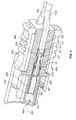
FIGs. 1-4 show an embodiment of a wire retaining system having anwire terminal 100 that is configured to be locked into connector housing 400 (seeFIG. 4 ) and to lockingly receiveelectrical wire 105.Electrical wire 105 includesconductor 107 andinsulation 109. The configuration ofwire 105 may be any configuration of wire that includes an insulated conductive portion.Suitable wires 105 include, but are not limited to, 18-gauge solid-core copper wire.Wire terminal 100 includes aterminal body 103, a locking portion ormember 111, defining a lockingshoulder 113 for engaging a surface of a connector housing 400 (see, e.g.,FIG. 4 ) to securely retainwire terminal 100 withinconnector housing 400. - As best viewed in
FIG. 2 ,terminal body 103 further includes acontact gripping element 201 arranged extending into anaperture 205 withinterminal body 103.Terminal body 103 further includes astop 207 in electrical communication withterminal body 103 that provides a surface onto which aconductor 107 may abut to establish a maximum insertion of wire 105 (see, e.g.,FIG. 3 ) insideterminal body 103. Stop 207 may be formed fromterminal body 103 or may be attached to theterminal body 103. Thecontact gripping element 201 may be cut or stamped out fromterminal body 103, but as shown, is stamped from a blank of material from which it is formed. Alternatively, contact grippingelement 201 may be separately provided and secured toterminal body 103. In this embodiment,wire terminal 100 is of unitary construction. Contact grippingelement 201 may be resiliently biased into the form of, for example, a leaf spring or beam structure. Thecontact gripping element 201 defines a wire trap for contacting an exposed conductor of an insulated wire or a conductor of an uninsulated wire or an electrically conductive contact having a similar cross-section. In the embodiment shown inFIGs. 1-4 , thewire terminal 100 further includes ablade 117 extending inwardly from theterminal body 103 intoaperture 205 toward aterminal center axis 203. - As shown in
FIGs. 1 and3 ,conductor 107 ofwire 105 is installed inwire terminal 100 by directingconductor 107 alongterminal center axis 203post blade 117 towardend 303 untilconductor 107 abuts stop 207. Stop 207 is shown as a tab that is biased inwardly intoaperture 205. However, stop 207 may also include a region of reduced cross-sectional area to provide a surface toabut conductor 107 when fully inserted insideaperture 205. - As best shown in
FIG. 1 ,blade 117 preferably extends towardterminal center axis 203 perpendicularly toterminal center axis 203. The extension of theblade 117 towardterminal center axis 203 is preferably such that theblade 117 contacts theinsulation 109 ofwire 105 inserted interminal 100. This contact is such that theblade 117 slices or shears a groove or channel 301 (seeFIGs. 3-4 ) in theinsulation 109 during insertion of thewire 105 into the terminal with thechannel 301 providing an engagement with thewire 105 to substantially prevent axial rotation between thewire 105 and the wire terminal aboutterminal center axis 203. Theblade 117 may also include a tapered edge (not shown) arranged parallel toterminal center axis 203 to reduce the force associated with insertingwire 105 and formingchannel 301. The position ofblade 117 may be any circumferential position onterminal body 103 that permits extension ofblade 117 towardwire 105. That is,blade 117 may extend intoaperture 205, but not necessarily aligning withterminal center axis 203. The extension ofblade 117 may provide achannel 301 in theinsulation 109, theconductor 107 or any combination thereof. In one embodiment of the invention, theblade 117 may be incorporated intocontact gripping element 201 wherein thechannel 301 is formed on theconductor 107. In addition, a plurality ofblades 117 may be utilized to further resist wire rotation. -
FIG. 4 shows a cross-sectional view of a connector housing illustrating awire terminal 100 according to an embodiment of the present invention arranged within theconnector housing 400, with a portion of theconnector housing 400 removed. Lockingmember 111 at the lockingshoulder 113 engages surface of theconnector housing 400 to substantially prevent disengagement of thewire terminal 100 from theconnector housing 400.Connector housing 400 may be configured in any manner that mates a second connector housing (see, e.g.,FIG. 13 ), wherein each of theconnector housing 400 andwire terminal 100 receives and engages aconductor 107 of awire 105 for electrical connection ofwires 105 to the second connector.Connector housing 400 is preferably fabricated from a non-electrically conductive material, such as, for example, conventional engineering grade thermoplastic. As shown inFIG. 4 , theconnector housing 400 and thewire terminal 100 are configured as a female connection viaaperture 205 atend 303 for receiving a male plug. Whilewire terminal 100 is shown as including a female connection atend 303, thewire terminal 100 may include a male plug atend 303 or any other structure that permits electrical communication between engaged connector housings. Theconnector housings 400 may be engaged in any suitable manner, including but not limited to, disenagable latches 401 that are disengagable by depressinglatch arms 403. Mating connector housings (not shown inFIG. 4 ) may include latch features 1301 (see, e.g.,FIG. 13 ) that engage latches 401 and substantially prevent disengagement of theconnector housings 400. In addition,connector housing 400 includes opening 405 that may have mating geometries that permit orientation of mating plugs only in desired configurations. Engagement ofconnector housings 400 and theircorresponding wire terminals 100 permits safe and easy electrical connection/disconnection ofwires 105 without the necessity of crimping, special tools or equipment. As shown inFIG. 4 , a plurality ofwires 105 may be inserted intoconnector housing 400, wherein the arrangements ofcorresponding wire terminals 100 may be the same or different than the arrangement shown inFIG. 4 . - The engagement of
blade 117 with rotation resistance is achieved by formation ofchannel 301, whereinchannel 301 has sufficient depth intoinsulation 109 and/orconductor 107 to provide substantial resistance to rotation aboutterminal center axis 203. While it is preferable to providechannel 301 into theinsulation 109 only, thechannel 301 may also be formed intoconductor 107. This rotational resistance allows thewire 105 engaged or trapped bycontact gripping element 201 to remain engaged and substantially prevents unintentional disengagement ofwire 105 due to rotation and pulling ofwire 105 aboutterminal center axis 203.Additional blades 117 provide additional rotational resistance, but also increase the amount of force required to insertwire 105. -
FIG. 5 shows a cross-sectional view of another embodiment of the present invention with a portion of theconnector housing 400 removed, including awire terminal 100 according to an embodiment of the present invention arranged withinconnector housing 400. The embodiment shown inFIG. 5 includes substantially the same arrangement ofconnector housing 400 andwire terminal 100 substantially as shown and described inFIG. 4 . Thewire terminal 100 in the embodiment shown inFIG. 5 may or may not includeblade 117. However,connector housing 400 further includes anangle channel 501 configured to conform wire 105 (i.e., bend) in a plurality of axes, including axes different thanterminal center axis 203. During insertion ofconductor 107 intoconnector housing 400, the wire is directed alongangle channel 501 in a direction at an angle toterminal center axis 203. As theconductor 107 is further inserted towardend 303 and pastangled channel 501, theconductor 107 is directed alongterminal center axis 203. Upon full insertion ofconductor 107, thewire 105 andconductor 107 are configured into at least a firstwire orientation section 503 which is oriented substantially parallel to and/or coincident with about theterminal center axis 203, a secondwire orientation section 505 which is oriented substantially parallel to and/or coincident with about anangle channel axis 506 and a thirdwire orientation section 507, which is oriented substantially parallel to and/or coincident with about afront opening axis 508. While the above has been described as three axes, the orientation of the insertedwire 105 may include greater than three axes and may include curved, rounded or twisted orientations along theangle channel 501 or exterior to theconnector housing 400. As shown inFIG. 5 , a plurality ofwires 105 may be inserted intoconnector housing 400, wherein the arrangements ofcorresponding wire terminals 100 and the presence and arrangement ofangle channel 501 may be the same or different than the arrangement shown inFIG. 5 . For example,angle channel 501 may include multiple orientations for directingwire 105 into a plurality of directions. Likewise, theangle channel 501 may be oriented at any angle or direction that provides an angle toterminal center axis 203. This embodiment of the present invention permits the easy engagement ofwire 105 while reducing or eliminating undesired/unintentional disengagement ofwire 105 from thewire terminal 100 and/or theconnector housing 400. -
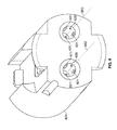
FIG. 6 illustrates a wire retaining system according to another embodiment of the present invention, including aconnector housing 400 havingopenings 600 configured to receive wires 105 (not shown inFIG. 6 ). Circumferentially about a surface ofopening 600, at least onerib 601 is configured to receivewire 105. Preferablyribs 601 are configured to engage theinsulation 109 ofwire 105. Theribs 601 may be of certain construction with theconnector housing 400 or may be attached toopening 600. Theribs 601 are preferably a non-conductive material of sufficient rigidity and having a geometry that grips theinsulation 109 and resists or prevents rotation ofwire 105 whenwire 105 is inserted rotationally about openingcenter axis 603. In another embodiment of the invention, a conductive material, such a metal may be utilized in theconnector housing 400 or as insert thereto, formingribs 601 forgripping wire 105. Theribs 601 may be oriented at an angle toopening center axis 603 or perpendicular toopening center axis 603. In other words,ribs 601 may or may not radially extend in alignment withopening center axis 603. In addition,ribs 601 preferably sufficiently engageinsulation 109 that the resistance to undesired/unintentional disengagement parallel toopening center axis 603 is likewise increased. As shown,ribs 601 are arranged substantially parallel to theopening center axis 603 ofopening 600. -
FIG. 7 illustrates a wire retaining system according to another embodiment of the present invention, including aconnector housing 400 havingopenings 600 configured to receive wires 105 (not shown inFIG. 7 ).Openings 600 may includeribs 601, as shown and described above with respect toFIG. 5 , and/or theconnector housing 400 may includewire terminal 100 structures, as described above with respect toFIGs. 1-5 . Theconnector housing 400 of this embodiment of the invention further includes a segmenting slot 700 extending through bothopenings 600 and through theconnector housing 400. The segmenting slot 700 is formed into theconnector housing 400 coplanar to a center axis of thewire 105 and provides a compliant force on an insulation portion of thewire 105 by segmenting portions of the connector body into pivoting portions. Segmenting slot 700 forms a pivotabletop member 701 and apivotable bottom member 703. Pivoting oftop member 701 andbottom member 703 preferably is facilitated by elastic deformation of the material making upconnector housing 400 but may be provided by an attached mechanical or formation of a hinge or hinge-like structure. The pivoting of thetop member 701 and/or thebottom member 703 decreases the resistance (i.e., force required for insertion) on the wire 105 (not shown inFIG. 7 ) by allowing a reduced force onwire 105 due to contact withtop member 701 andbottom member 703 and structures, such asribs 601, extending inwardly alongopenings 600. The reduced resistance to insertion permits the utilization of additional wire retention structures, such asblade 117,contact gripping element 201 andribs 601, and other structures that increase resistance toelectrical wire 105 insertion, intoconnector housing 400. This embodiment of the present invention permits the simple and easy engagement ofwire 105 while permitting the use of wire retention structures to reduce or eliminate undesired/unintentional disengagement ofwire 105 from thewire terminal 100 and/or theconnector housing 400. -
FIG. 8 illustrates a wire retaining system according to another embodiment of the present invention, including aconnector housing 400 havingopenings 600 configured to receivewires 105.Connector housing 400 may includewire terminal 100 structures (not shown inFIG. 8 ) and/orribs 601 to provide wire retention, as described above with respect toFIGs. 1-6 . However, the embodiment shown inFIG. 8 further includes aretention plate 800 havingopenings 600 configured to allow insertion ofwire 105. In addition, the periphery of opening 600 includes a plurality offingers 801 extending inward toward theopening center axis 603 ofopening 600. Thesefingers 801 are configured to grip theinsulation 109 ofwire 105 and provide resistance against unintentional disengagement ofwire 105 in response to a pulling and/or twisting force directed alongopening center axis 603.Plate 800 is preferably a non-electrically conductive material, such as a polymeric material that is sufficiently rigid to provide resistance in response to pulling and/or twisting forces directed alongopening center axis 603. For example,plate 800 may be fabricated from a mylar film.Plate 800 is preferably attached to a surface ofconnector housing 400.Plate 800 may be attached toconnector housing 400 in any conventional manner, including, but not limited to adhesives or thermal bonding. However,plate 800 may also be fabricated as a unitary piece withconnector housing 400. In addition,plate 800 may be partitioned into afirst plate segment 803 and asecond plate segment 805, wherein each plate segment may be provided with color, marking or other indicia to indicate proper installation and/or configuration ofwires 105. The addition ofplate 800 to theconnector housing 400 provides resistance against undesirable/unintentional disengagement ofwire 105 in response to a pulling force directed alongopening center axis 603. -
FIG. 9 illustrates a wire retaining system according to still another embodiment of the present invention, including aconnector housing 400 havingwire terminal 100 incorporated therein. The embodiment shown inFIG. 9 includes substantially the same arrangement ofconnector housing 400 andwire terminal 100 substantially as shown and described inFIG. 4 . Thewire terminal 100 in the embodiment shown inFIG. 5 may or may not includeblade 117.Opening 600 is formed intoconnector housing 400, wherein opening is configured to receive a gripping structure orgrommet 900.Grommet 900 includes a non-electrically conductive material, such as a polymeric or rubber material, which grip and/or apply frictional sliding resistance to wire 105 and/orconnector housing 400. Thegrommet 900 may be incorporated intoconnector housing 400 or may be attached or installed ontowire 105. Thegrommet 900 may also utilize an adhesive, such as a pressure sensitive adhesive tofurther grip wire 105 and provide additional resistance in response to pulling and/or twisting. Thegrommet 900 preferably provides sufficient frictional sliding resistance to substantially prevent undesirable/unintentional disengagement ofwire 105 fromwire terminal 100 and/orconnector housing 400. -
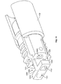
FIG. 10 illustrates a wire retaining system according to still another embodiment of the present invention, including aconnector housing 400 having wire terminal 100 (not shown inFIG. 10 ) incorporated therein for receiving a wire 105 (not shown inFIG. 10 ).Connector housing 400 further includes aretention member 1000, which extends fromconnector housing 400.Retention member 1000 includes a "T" shape, whereinarms 1003 extend to form aslot 1005 betweenarms 1003 andconnector housing 400.Slot 1005 has a geometry permitting the insertion of a wire or cable tie 1201 (see e.g.,FIG. 12 ), or other device capable of substantially immobilizingwires 105.Cable tie 1201 may be inserted intoslot 1005, wherein the wire retention structure provides surfaces that prevent thecable tie 1201 from slipping or moving in a direction away fromconnector housing 400. Thecable tie 1201 also provides wire retention by providing a sufficient circumferential force inward towardretention member 1000 to retainwires 105 adjacent toretention member 1000 and substantially prevent undesirable/unintentional disengagement ofwire 105 fromwire terminal 100 and/orconnector housing 400. In addition,wire 105 may be oriented around (i.e., wrapped around)wire retention member 1000 in a manner that provides orientation ofwire 105 in a plurality of axes and provides additional resistance to pulling and/or twisting. -
FIG. 11 illustrates a wire retaining system according to still another embodiment of the present invention, including aconnector housing 400 having wire terminal 100 (not shown inFIG. 11 ) incorporated therein for receiving a wire 105 (not shown inFIG. 11 ).Connector housing 400 further includes aretention member 1000, which extends fromconnector housing 400.Retention member 1000 is formed into a "T" shape, whereinarms 1003 extend to form aslot 1005 betweenarms 1003 andconnector housing 400.Arms 1003 further include wire guides 1101, which are configured to permit insertion ofwire 105 through the wire guides 1101 and intoopening 600. The wire guides 1101 form openings or channels through which the wire may be inserted to permit the guided insertion ofwires 105 intoopenings 600.Retention member 1000 may be formed intoconnector housing 400 as a unitary piece or may be attached toconnector housing 400. -
FIG. 12 includes an embodiment of the present invention including the retention member shown and described with respect toFIG. 11 . In addition,FIG. 12 includeswires 105 and acable tie 1201 arranged inslots 1005 wherein thecable tie 1201 provides at least a partial inwardly directed circumferential force to retainwires 105 in position.Cable tie 1201 is any device capable of providing a force onwires 105 within slot orslots 1005 that provides resistance to both pulling and rotation. In addition to cable ties, adhesive structures, such as tape, labeling or other wire immobilizing device may also be utilized. The inward retaining force provided bycable tie 1201 is preferably sufficient to provide resistance to unintentional disengagement of thewires 105 due to pulling of thewires 105 and/or rotation of thewires 105. -
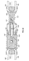
FIG. 13 illustrates a cross-sectional view ofconnector housing 400 engaged with a second connector housing 400', wherein thewire 105 and wire terminal 100,100' are shown in elevational cross-sectional view. The connection ofconnector housings 400 and 400' permits the electrical connection ofwire 105 with wire 105' by electrical communication betweenwire terminal 100 and 100' atjunction 1300.Junction 1300 preferably includes coupling of a male plug with a female connection, each corresponding to one ofconnector housing 400 or connector housing 400'. The engagement ofconnector housing 400 to connector housing 400' takes place by engagement of disenagable latches 401 of connector housing 400' engagingconnector feature 1301 ofconnector housing 400. The engagement of disengagable latches 401 andconnector feature 1301 provides a latched position capable of resisting a retention force between theconnector housings 400 and 400'. - In a preferred embodiment, the wire retention of
wires 105 is sufficient that forces onwire 105 provide for disengagement oflatches 401 andfeature 1301 at a lesser force than the force required to disengagewires 105 fromconnector housing 400. - As further shown in
FIG. 13 ,cable tie 1201 may be positioned inslot 1005,adjacent wire 105. Thecable tie 1201 provides force againstwire 105 andretention member 1000. The force provided bycable tie 1201 provides resistance to or prevention of unintentional disengagement ofwire 105 in response to a pulling force directed alongopening center axis 603. -
FIG. 14 illustrates a wire retaining system according to still another embodiment of the present invention, including aconnector housing 400 having wire terminal 100 (not shown inFIG. 14 ) incorporated therein for receiving a wire 105 (not shown inFIG. 14 ).Connector housing 400 includesopening 600, wherein the opening may extend along a substantially singular axis to wire terminal 100 (see, e.g.,FIG. 4 ), or may include anangle channel 501, such as the structure shown inFIG. 5 .Connector housing 400 further includes aretention member 1000, which extends fromconnector housing 400.Retention member 1000 is formed into acenter retention member 1400 and twoside retention members 1403 each configured to provide awire retention guide 1401, which receives thewire 105 and provides a joggle or bend in thewire 105, which provides resistance to pulling and rotation, once thewire 105 is engaged inwire retention guide 1401. -
FIG. 15 shows theconnector housing 400 shown and described with respect toFIG. 14 wherein awire 105 is installed in eachwire retention guide 1401. Thewire 105 may be installed by insertingwire 105 alongopening center axis 603. Thewire 105 is inserted intoconnector housing 400 untilwire 105 is engaged with wire terminal 100 (not shown inFIG. 15 ). After thewire 105 is fully inserted, thewire 105 protruding from opening 600 is then brought into contact with a surface ofwire retention member 1000 betweencenter retention member 1400 and one of the twoside retention members 1403. Thewire 105 is then guided intowire retention guide 1401. Thewire 105 is preferably permitted to snap into thewire retention guide 1401 by elastic deformation of thewire retention member 1000. Snapping, as used herein, indicates a compliant force or elastic resistance that permits the introduction and/or retention of awire 105 or other structure by virtue of a force that is overcome by application of a greater counter force. In other words, spacing betweenside retention member 1403 andcenter retention member 1400 is less than the diameter ofwire 105, the elastic resistance betweenside retention member 1403 andretention member 1400 initially presenting access ofwire 105 intowire retention guide 1401. However, upon application of sufficient force applied towire 105,wire 105 overcomes the retention force betweenside retention member 1403 andretention member 1400 and decreasewire retention guide 1401. Upon accessingwire retention guide 1401, thewire 105 may then be further oriented or bent to the desired direction of wire installation. Theretention member 1000 retains thewire 105 in position with a plurality of bends aligned in a plurality of axes. These bends provide addition resistance to pulling along theopening center axis 603 and resists or prevents undesirable/unintentional disengagement ofwire 105 fromconnector housing 400.Retention member 1000 is configured to provide awire retention guide 1401, which receives the wire and provides a joggle or narrow bend portion in thewire 105, which provides resistance to pulling and rotation, once thewire 105 is engaged inwire retention guide 1401. -
FIG. 16 illustrates aconnector housing 400 engaged with a second connector housing 400'.Connector housing 400 and connector housing 400' are engaged in the manner shown and described above with respect toFIG. 13 . As shown,wire 105, 105' is positioned withinwire retention guide 1401, 1401' ofwire retention member wire 105, 105' andretention member wire 105, 105' in response to a pulling force directed alongopening center axis 603. -
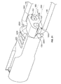
FIG. 17 illustrates a wire retaining system according to still another embodiment of the present invention, including aconnector housing 400 having wire terminal 100 (not shown inFIG. 17 ) incorporated therein for receiving a wire 105 (not shown inFIG. 17 ).Connector housing 400 further includes aretention member 1000, which extends fromconnector housing 400.Retention member 1000 is formed into a "T" shape, whereinarms 1003 extend to form aslot 1005 betweenarms 1003 andconnector housing 400.Retention member 1000 may be formed intoconnector housing 400 as a unitary piece or may be attached toconnector housing 400.Arms 1003 further includewire guide 1101 andarm slot 1701, which are configured to permit insertion ofwire 105 throughwire guide 1101 and intoopening 600, wherein thewire 105 may further be brought into contact witharm slot 1701 and permitted to snap out ofwire guide 1101 by elastic deformation or other mechanism ofarm 1003 adjacent toarm slot 1701, such as previously discussed with regard toFIG. 15 . The positioning of thewire 105 outside thewire guide 1101 permitswire 105 to be oriented along a plurality of axes (i.e., to have a plurality of bends). These bends provide addition resistance to pulling along theopening center axis 603 and resists or prevents undesirable/unintentional disengagement ofwire 105 from connector housing 400 (see, e.g.,FIGs. 21 and22 ). Thus, removal ofwire 105 fromwire guide 1101 througharm slot 1701 provides a joggle or bend in thewire 105, which provides resistance to pulling and rotation once the wire is engaged adjacent toretention member 1000. -
FIG. 18 illustrates a wire retaining system according to still another embodiment of the present invention, including aconnector housing 400 having wire terminal 100 (not shown inFIG. 18 ) incorporated therein for receiving a wire 105 (not shown inFIG. 18). FIG. 18 includes substantially the same arrangement ofconnector housing 400,openings 600,wire retention member 1000,arm 1003,wire guide 1101, andarm slot 1701, as shown and described with respect toFIG. 17 . However, the embodiment shown inFIG. 18 further includesside guards 1801 configured to permit the passage ofwire 105 out ofwire guide 1101, but substantially prevents the reinsertion ofwire 105 intowire guide 1101. In addition, the structure ofFIG. 18 provides addition wire dress and/or wire management in connector systems and the storage/transportation of connector systems. -
FIG. 19 illustrates a wire retaining system according to still another embodiment of the present invention, including aconnector housing 400 having wire terminal 100 (not shown inFIG. 19 ) incorporated therein for receiving a wire 105 (not shown inFIG. 19). FIG. 19 includes substantially the same arrangement ofconnector housing 400,openings 600,wire retention member 1000,arm 1003,wire guide 1101, andarm slot 1701, as shown and described with respect toFIG. 17 . However, the embodiment shown inFIG. 19 further includes guard features 1901 configured to permit the passage ofwire 105 out ofwire guide 1101, but substantially prevents the reinsertion ofwire 105 intowire guide 1101. In addition, the guard features 1901 act to limit rotation of the wire disposed within theslot 1005. Specifically, the guard features preferably provide guidance for the wire to a position away fromarm slot 1701 and substantially confines movement ofwire 105 to either side ofguard feature 1901. -
FIG. 20 illustrates a wire retaining system according to still another embodiment of the present invention, including aconnector housing 400 having wire terminal 100 (not shown inFIG. 20 ) incorporated therein for receiving a wire 105 (not shown inFIG. 20). FIG. 20 includes substantially the same arrangement ofconnector housing 400,openings 600,wire guide 1101, andarm slot 1701, as shown and described with respect toFIG. 17 . However, thewire retention member 1000 includes sidewalls 2000 extending fromarms 1003 to theconnector housing 400. Thesidewalls 2000 andwire retention member 1000 are configured to provide aside opening 2003 for receiving and retaining wire 105 (seeFIG. 21 ). The configuration ofFIG. 20 provides improved strength of thewire retention member 1000 by formation ofsidewalls 2000, which resists breakage. In addition, the formation ofsidewalls 2000 reduces or eliminates surfaces susceptible to snagging, particularly during storage and/or transportation, wherein a plurality of wire connector systems and their associatedwires 105 may be present. In addition, the reentry of the wire intoslot 1701 is made difficult because the formation ofsidewall 2000 provides a surface against which little or no deflection may take place. In other words, in order forwire 105 to reenter wire guide, thearm 1003 must deflect a distance substantially equal to the diameter ofwire 105, which requires a greater force than deflection of two opposingarms 1003, as shown, for example, inFIG. 17 . -
FIG. 21 shows theconnector housing 400 shown and described with respect toFIG. 20 wherein awire 105 is installed. Thewire 105 is installed by insertingwire 105 alongopening center axis 603. Thewire 105 is inserted intoconnector housing 400 untilwire 105 is engaged with wire terminal 100 (not shown inFIG. 21 ). After thewire 105 is fully inserted, thewire 105 extending past the end ofconnector housing 400 is then brought into contact with a surface ofslot 1701. Thewire 105 is then guided intoside opening 2003. Thewire 105 is preferably permitted to snap outside ofwire guide 1101 intoside opening 2003 by elastic deformation of thewire retention member 1000 as previously discussed with regard toFIG. 15 . Thewire 105 may then be further oriented or bent to the desired direction of wire installation. Thewire retention member 1000 retains thewire 105 in position with a plurality of bends oriented in a plurality of axes. These bends provide addition resistance to pulling along theopening center axis 603 and resists or prevents undesirable disengagement ofwire 105 fromconnector housing 400.Retention member 1000 is configured to provide aside opening 2003, which receives thewire 105 and provides a joggle or bend in thewire 105, which provides resistance to pulling and rotation, once thewire 105 is engaged inside opening 2003. -
FIG. 22 illustrates aconnector housing 400 engaged with a second connector housing 400'.Connector housing 400 and connector housing 400' are engaged in the manner shown and described above with respect toFIG. 13 . As shown,wire 105, 105' is positioned withinside opening 2003, 2003' ofwire retention member wire 105, 105' adjacent toretention member wire 105, 105' in response to a pulling force directed alongopening center axis 603. -
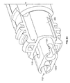
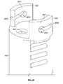
FIGs. 23 and24 illustrate a wire retaining system according to still another embodiment of the present invention, including aconnector housing 400 having wire terminal 100 (not shown inFIGs. 23 or24 ) incorporated therein for receiving a wire 105 (not shown inFIGs. 23 or24 ).Connector housing 400 further includes aretention member 1000, which extends fromconnector housing 400.Retention member 1000 includes a plurality of wire guides 1101, arranged as passages and/or openings inretention member 1000 configured to receivewire 105 in a manner that allows threading thewire 105 through passages to form multiple loops, bends and/or joggles, wherein thewires 105 are aligned along a plurality of axes. -
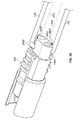
FIG. 25 shows theconnector housing 400 shown and described with respect toFIGs. 23 and24 , wherein awire 105 is installed. Thewire 105 is installed by insertingwire 105 alongopening center axis 603. Thewire 105 is inserted intoconnector housing 400 untilwire 105 is engaged with wire terminal 100 (not shown inFIG. 25 ). After thewire 105 is fully inserted, thewire 105 is then bent at an angle substantially perpendicular to theopening center axis 603 and positioned withinwire guide 1101. Thewire 105 is then threaded throughwire guide 1101 located substantially at the center ofwire retention member 1000, wherein thewire 105 is passed through theretention member 1000 and again bent in the desired direction of use. Thewire retention member 1000 retains thewire 105 in position with a plurality of bends aligned in a plurality of axes. These bends provide addition resistance to pulling along theopening center axis 603 and resists or prevents undesirable disengagement ofwire 105 fromconnector housing 400.Retention member 1000 is configured to provide a pluarality of wire guides 1101, which receives thewire 105 and provides a joggle or bend in thewire 105, which provides resistance to pulling and rotation, once thewire 105 is engaged in wire guides 1101. -
FIG. 26 illustrates aconnector housing 400 engaged with a second connector housing 401' showing the positioning ofwires 105, 105', as described above with respect toFIG. 25 .Connector housing 400 and connector housing 400' are engaged in the manner shown and described above with respect toFIG. 13 . As shown,wire 105, 105' is positioned within wire guides 1101, 1101' ofwire retention member wire 105, 105' andretention member wire 105, 105' in response to a pulling force directed alongopening center axis 603. -
FIG. 27 illustrates a wire retaining system according to still another embodiment of the present invention, including aconnector housing 400 having wire terminal 100 (not shown inFIG. 27 ) incorporated therein for receiving a wire 105 (not shown inFIG. 27 ).Connector housing 400 includes awire retention member 1000 and awire guide 1101 incorporated into theconnector housing 400. As shown inFIG. 27 ,wire 105 is inserted intoopening 600 and threaded throughwire retention member 1000 andwire guide 1101. As shown,wire retention member 1000 andwire guide 1101 are bound inlatch arms 403. The threading of thewire 105 results in a bend or joggle in thewire 105 that provides alignment along a plurality of axes, which provides resistance to pulling and rotation, once thewire 105 is engaged and threaded throughwire retention member 1000 andwire guide 1101. -
FIG. 28 illustrates a wire retaining system according to still another embodiment of the present invention, including aconnector housing 400 having wire terminal 100 (not shown inFIG. 28 ) incorporated therein for receiving a wire 105 (not shown inFIG. 28). FIG. 28 includes substantially the same arrangement ofconnector housing 400 andopenings 600, as shown and described with respect toFIG. 17 . However, the embodiment shown inFIG. 28 further includes awire retention member 1000 that is configured with twoinsertion arms 2801 having aninsertion slot 2800 and aninsertion opening 2803. While the embodiment shown inFIGs. 28-30 show twoinsertion arms 2801, any number ofinsertion arms 2801 may be utilized. -
FIG. 29 shows theconnector housing 400 shown and described with respect toFIG. 28 , wherein awire 105 is installed. Thewire 105 is installed by insertingwire 105 alongopening center axis 603. Thewire 105 is inserted intoconnector housing 400 untilwire 105 is engaged with wire terminal 100 (not shown inFIG. 29 ). After thewire 105 is fully inserted, thewire 105 extending from opening 600 is then bent at an angle substantially perpendicular toopening center axis 603. Thewire 105 is then guided intoinsertion slot 2800 ofinsertion arm 2801 and alonginsertion slot 2800 until thewire 105 is positioned ininsertion opening 2803. Thewire 105 is preferably permitted to snap intoinsertion opening 2803 by elastic deformation of theinsertion arm 2801 as previously discussed with regard toFIG. 15 . Thewire 105 may then be further bent or oriented to the desired direction ofwire 105 installation. Thewire retention member 1000 retains thewire 105 in position with a plurality of bends aligned in a plurality of axes. These bends provide addition resistance to pulling along theopening center axis 603 and resists or prevents undesirable disengagement ofwire 105 fromconnector housing 400.Retention member 1000 is configured to provideinsertion opening 2803, which receives thewire 105 and provides a joggle or bend in thewire 105, which provides resistance to pulling and rotation, once thewire 105 is engaged ininsertion opening 2803. -
FIG. 30 illustrates aconnector housing 400 engaged with a second connector housing 400'.Connector housing 400 and connector housing 400' are engaged in the manner shown and described above with respect toFIG. 13 . As shown,wire 105 is positioned withininsertion opening 2803, 2803' ofwire retention member wire 105, 105' andretention member wire 105, 105' in response to a pulling force directed alongopening center axis 603. -
FIG. 31 illustrates a wire retaining system according to still another embodiment of the present invention, including aconnector housing 400 having wire terminal 100 (not shown inFIG. 31 ) incorporated therein for receiving a wire 105 (not shown inFIG. 31). FIG. 31 includes substantially the same arrangement ofconnector housing 400,openings 600,wire retention members 1000,insertion arms 2801 as shown and described with respect toFIGs. 28-30 . However, the embodiment shown inFIG. 31 includes awire retention member 1000 that is configured with oneinsertion arm 2801.Insertion arm 2801 includes aninsertion slot 2800 and aninsertion opening 2803 configured to receive eachwire 105 of a plurality ofwires 105. -
FIG. 32 shows theconnector housing 400 shown and described with respect toFIG. 31 , wherein twowires 105 installed intoinsertion arm 2801. Thewire 105 is installed by insertingwire 105 alongopening center axis 603. Thewire 105 is inserted intoconnector housing 400 untilwire 105 is engaged with wire terminal 100 (not shown inFIG. 32 ). After thewire 105 is fully inserted, thewire 105 extending fromconnector housing 400 is then bent at an angle substantially perpendicular toopening center axis 603guiding wire 105 intoinsertion slot 2800 ofinsertion arm 2801 and alonginsertion slot 2800 until thewire 105 is positioned ininsertion opening 2803. Thewire 105 is preferably permitted to snap intoinsertion opening 2803 by elastic deformation of theinsertion arm 2801 as previously discussed with respect toFIG. 15 . Thewire 105 may then be further bent or oriented to the desired direction ofwire 105 installation. Thewire retention member 1000 retains thewire 105 in position with a plurality of bends aligned in a plurality of axes. These bends provide addition resistance to pulling along theopening center axis 603 and resists or prevents undesirable disengagement ofwire 105 fromconnector housing 400.Retention member 1000 is configured to provideinsertion opening 2803, which receives thewire 105 and provides a joggle or bend in thewire 105, which provides resistance to pulling and rotation, once thewire 105 is engaged inopening 2803. - While the above has described embodiments of wire retention structures, components and methods, the present invention is not limited to the embodiments described above. In particular, the present invention may include a single
wire retention member 1000, component or method or may include a combination of a plurality of structures, components and methods. For example, a connector according to an embodiment of the present invention may include anwire terminal 100 having ablade 117, may includeangle channel 501,ribs 601, segmenting slot 700,fingers 801,wire retention member 1000 and any combinations thereof. The various structures are not limited to those structures shown and may include additional channels, slots, grooves or other features for retaining awire 105 adjacent thereto. In addition, devices such ascable ties 1201, may be used in combination with thewire retention member 1000 to further provide resistance to unintentional disengagement due to pulling and/or rotation. - While the invention has been described with reference to a preferred embodiment, it will be understood by those skilled in the art that various changes may be made and equivalents may be substituted for elements thereof without departing from the scope of the invention. In addition, many modifications may be made to adapt a particular situation or material to the teachings of the invention without departing from the essential scope thereof. Therefore, it is intended that the invention not be limited to the particular embodiment disclosed as the best mode contemplated for carrying out this invention, but that the invention will include all embodiments falling within the scope of the appended claims.
- In one embodiment of the invention the wire retaining connector comprises: a connector body having at least one opening configured to receive a wire, the wire including a partially exposed conductor and insulation, the connector body further comprising a wire retention member having at least one surface onto which a wire may be engaged, the wire retention member providing sufficient retention of the wire to resist rotation and disconnection of the wire from the connector body. Preferably the connector body further includes a wire terminal configured to receive a wire along an axis and at least a portion of insulation surrounding a conductive portion of the wire, the wire terminal having a blade arranged to contact the insulation; wherein the blade forms a channel in the insulation during insertion of the wire into the terminal, the channel sufficiently engaging the blade to substantially resist rotational movement between the wire and the wire terminal. Preferably the blade includes a taper arranged parallel to the axis to reduce the force required to insert the wire and form the channel. Preferably the wire retention member extends from a surface of the connector body. Preferably the opening is configured to receive the wire along a first axis. Preferably the connector body includes a channel arranged at an angle to the first axis. Preferably the wire retention member is a T-shaped member extending from a surface of the connector body. Preferably the T-shaped member further includes openings through which the wires may be inserted. Preferably the T-shaped member is configured to form a slot between the surface of the connector body and the T-shaped member, the slot having a geometry that permits further installation of a cable tie. Preferably the wire retention member comprises protrusions from a surface of the opening that engage the wire in a manner that substantially prevents rotation along the first axis. Preferably the wire retention member comprises a geometry having a plurality of surfaces configured to retain the wire. Preferably the plurality of surfaces form wire guides into which the wire may be positioned and retained. Preferably the wire retention member includes at least one passage through which the wire may be inserted, the passage being configured at an angle to the first axis. Preferably the wire retention member is fabricated from a material capable of elastic deformation to provide a snapping of the wire into or out of a wire guide. Preferably the wire retention member is incorporated into a feature of the connector body. Preferably the wire retention member comprises a wire retention member within the connector body, the wire retention member being oriented along a first axis and having at least one rib that contacts and retains the wire. Preferably the at least one opening further comprises a slot formed into the connector body, the slot being coplanar to a center axis of the wire and providing a compliant force on an insulation portion of the wire when the wire is inserted into the opening. Preferably the compliant force is sufficient to substantially prevent rotation of the wire about the center axis. Preferably the wire retention member further comprises a plurality of retention passages, each retention passage being arranged at an angle to the first axis, the retention passages being configured to receive the wire. Preferably the connector further comprises a gripping structure in contact with a portion of the connector housing and the wire to provide frictional resistance therebetween. Preferably the gripping structure is a grommet.
- In a further embodiment of the invention the wire retention connector system comprises: a first connector body and a second connector body each, independently, having at least one opening configured to receive a wire, the wire including a partially exposed conductor and insulation, the connector body further comprising a wire retention member having at least one surface onto which a wire may be engaged, the wire retention member providing sufficient retention of the wire to resist rotation and disconnection of the wire from the connector body; wherein the first connector body and the second connector body include features that disengagably connect the first connector body to the second connector body. Preferably the connector body further includes a wire terminal configured to receive a wire along an axis and at least a portion of insulation surrounding a conductive portion of the wire, the wire terminal having a blade arranged to contact the insulation; wherein the blade forms a channel in the insulation during insertion of the wire into the terminal, the channel sufficiently engaging the blade to substantially resist rotational movement between the wire and the wire terminal. Preferably the blade includes a taper arranged parallel to the axis to reduce the force required to insert the wire and form the channel. Preferably the engagement between the first connector body and the second connector body disengages at a pulling force applied to the wires less than a pulling force resulting in disengagement of the wire from the connector body. Preferably the wire retention member extends from a surface of the connector body. Preferably the opening is configured to receive the wire along a first axis. Preferably the connector body includes channel arranged at an angle to the first axis. Preferably the wire retention member is a T-shaped member extending from a surface of the connector body. Preferably the T-shaped member further includes openings through which the wires may be inserted. Preferably the T-shaped member is configured to form a slot between the surface of the connector body and the T-shaped member, the slot having a geometry that permits further installation of a cable tie. Preferably the wire retention member comprises protrusions from a surface of the opening that engage the wire in a manner that substantially prevents rotation along the first axis. Preferably the wire retention member comprises a geometry having a plurality of surfaces configured to retain the wire. Preferably the plurality of surfaces form wire guides into which the wire may be positioned and retained. Preferably the wire retention member includes at least one passage through which the wire may be inserted, the passage being configured at an angle to the first axis. Preferably the wire retention member is fabricated from a material capable of elastic deformation to provide a snapping of the wire into or out of a wire guide. Preferably the wire retention member is incorporated into a feature of the connector body. Preferably the wire retention member comprising a wire retention member within the connector body, the wire retention member being oriented along a first axis and having at least one rib that contacts and retains the wire. Preferably the at least one opening further comprises a slot formed into the connector body, the slot being coplanar to a center axis of the wire and providing a compliant force on an insulation portion of the wire when the wire is inserted into the opening. Preferably the compliant force is sufficient to substantially prevent rotation of the wire along the center axis. Preferably the wire retention member further comprises a plurality of retention passages, each retention passage being arranged at an angle to the first axis, the retention passages being configured to receive the wire. Preferably the connector system further comprises a gripping structure in contact with a portion of the connector housing and the wire to provide frictional resistance therebetween. Preferably the gripping structure is a grommet.
- In a further embodiment of the invention the wire retaining connector comprises: a wire terminal configured to receive a wire and at least a portion of insulation surrounding a conductive portion of the wire along an axis; the wire terminal having a blade arranged perpendicular to the axis, the blade extending a distance inward from a surface of the wire terminal sufficient to contact the insulation; wherein the blade forms a channel in the insulation during insertion of the wire into the terminal, the channel sufficiently engaging the blade to substantially resist rotation between the wire and the wire terminal. Preferably the blade includes a taper arranged parallel to the axis to reduce the force required to insert the wire and form the channel. Preferably the wire terminal includes a plurality of blades.
Claims (13)
- An electrical connector having a connector housing (400) having at least one opening (600) configured to receive a wire (105) along an opening center axis (603) and a wire retention member (1000) with a wire guide (1101), a slot (1701) of the wire retention member (1000) configured to allow a wire (105) received in the opening (600) to be removed from the wire guide (1101) through the slot (1701) to provide a joggle or bend in the wire (105) to provide resistance to pulling and rotation of the wire (105).
- The electrical connector of claim 1 including a side guard (1801, 1901) configured to permit passage of the wire (105) out of the wire guide (1101) but substantially prevent the reinsertion of the wire (105) into the wire guide (1101).
- The electrical connector of claim 1 wherein the retention member (1000) includes sidewalls (2000) extending from arms (1003) thereof to the connector housing (400).
- The electrical connector of claim 3 wherein the sidewalls (2000) and the wire retention member (1000) are configured to provide a side opening (2003) for receiving and retaining the wire (105).
- The electrical connector of any preceding claim wherein the wire retention member (1000) is T-shaped wherein arms (1003) thereof extend to form a slot (1005) between each arm (1003) and the connector housing (400).
- The electrical connector of any preceding claim wherein the wire retention member (1000) is fabricated from a material capable of elastic deformation to provide a snapping of the wire (105) into or out of the wire guide (1101).
- The electrical connector of any preceding claim wherein the wire retention member (1000) extends from the connector housing (400).
- The electrical connector of any preceding claim wherein the wire retention member (1000) is incorporated into a feature of a connector body of the connector housing (400).
- The electrical connector of any preceding claim further including a wire terminal (100) incorporated in the connector housing (400) for receiving the wire (105) inserted along the opening center axis (603).
- The electrical connector of claim 9 wherein the wire terminal (100) is a poke-in terminal.
- A method of connecting a wire (105) to an electrical connector comprising the steps of:(i) providing a connector having a connector housing (400) having at least one opening (600) configured to receive the wire (105) along an opening center axis (603) and a wire retention member (1000) with a wire guide (1101);(ii) inserting the wire through the wire guide (1101) into the opening (600); and(iii) removing the wire (105) from the wire guide (1101) through a slot (1701) in the wire guide (1101) to provide a joggle or bend in the wire (105) to provide resistance to pulling and rotation of the wire (105).
- The method of claim 11 wherein the step of inserting the wire (105) into the opening (600) includes inserting the wire (105) into the connector housing (400) until the wire is engaged with a terminal (100) incorporated in the connector housing (400).
- The method of claim 11 wherein the step of inserting the wire (105) into the opening (600) includes inserting the wire (105) into the connector housing (400) until the wire is engaged with a poke-in terminal (100) incorporated in the connector housing (400).
Applications Claiming Priority (3)
| Application Number | Priority Date | Filing Date | Title |
|---|---|---|---|
| US11/555,947 US8386022B2 (en) | 2005-11-03 | 2006-11-02 | Multifaceted tracker device for computer-assisted surgery |
| EP07861512A EP2080249A2 (en) | 2006-11-02 | 2007-10-25 | Wire retention connector system |
| PCT/US2007/022628 WO2008057243A2 (en) | 2006-11-02 | 2007-10-25 | Wire retention connector system |
Related Parent Applications (1)
| Application Number | Title | Priority Date | Filing Date |
|---|---|---|---|
| EP07861512A Division EP2080249A2 (en) | 2006-11-02 | 2007-10-25 | Wire retention connector system |
Publications (2)
| Publication Number | Publication Date |
|---|---|
| EP2685569A1 true EP2685569A1 (en) | 2014-01-15 |
| EP2685569B1 EP2685569B1 (en) | 2019-03-27 |
Family
ID=39271490
Family Applications (2)
| Application Number | Title | Priority Date | Filing Date |
|---|---|---|---|
| EP13187082.6A Not-in-force EP2685569B1 (en) | 2006-11-02 | 2007-10-25 | Wire retention connector system |
| EP07861512A Withdrawn EP2080249A2 (en) | 2006-11-02 | 2007-10-25 | Wire retention connector system |
Family Applications After (1)
| Application Number | Title | Priority Date | Filing Date |
|---|---|---|---|
| EP07861512A Withdrawn EP2080249A2 (en) | 2006-11-02 | 2007-10-25 | Wire retention connector system |
Country Status (7)
| Country | Link |
|---|---|
| EP (2) | EP2685569B1 (en) |
| JP (1) | JP5197619B2 (en) |
| KR (1) | KR101098156B1 (en) |
| CN (1) | CN101548439B (en) |
| CA (1) | CA2668110C (en) |
| MX (1) | MX2009004709A (en) |
| WO (1) | WO2008057243A2 (en) |
Families Citing this family (4)
| Publication number | Priority date | Publication date | Assignee | Title |
|---|---|---|---|---|
| KR20130014548A (en) | 2010-03-08 | 2013-02-07 | 에어로바이론먼트, 인크. | Isolated cable connectors |
| DE102014117804B4 (en) * | 2014-12-03 | 2019-05-23 | Amphenol-Tuchel Electronics Gmbh | Field attachable stamped insulation displacement contact and method of making an insulation displacement contact connection |
| JP6610955B2 (en) * | 2016-06-07 | 2019-11-27 | 住友電装株式会社 | connector |
| US11411334B2 (en) * | 2020-01-03 | 2022-08-09 | Aptiv Technologies Limited | Electrical connector for connecting to flat-wire conductors of a flexible printed circuit |
Citations (4)
| Publication number | Priority date | Publication date | Assignee | Title |
|---|---|---|---|---|
| US3836938A (en) * | 1972-09-13 | 1974-09-17 | J Barrett | Safety electrical plug release mechanism |
| US3909099A (en) * | 1974-06-14 | 1975-09-30 | Anderson Power Products | Electrical connector with movably mounted cable clamp |
| US4868905A (en) * | 1988-03-28 | 1989-09-19 | Viscusi David A | Motor and other apparatus with novel power lead attachment structure |
| US20010055912A1 (en) * | 1998-09-14 | 2001-12-27 | Takayuki Nagata | Connector |
Family Cites Families (12)
| Publication number | Priority date | Publication date | Assignee | Title |
|---|---|---|---|---|
| GB564419A (en) * | 1943-01-13 | 1944-09-27 | Emil Samuel Conradi | Improvements in or relating to electric coupling devices, particularly of the plug-and-socket type, and anchoring means therefor |
| DE8000604U1 (en) * | 1980-01-11 | 1980-04-24 | Tony Adels, Elektro- Und Waermetechnik Gmbh & Co Kg, 5060 Bergisch Gladbach | Strain relief device for a terminal body or connector for electrical conductors and the like |
| DE3408115C2 (en) * | 1984-03-06 | 1986-12-18 | Messerschmitt-Bölkow-Blohm GmbH, 8012 Ottobrunn | Lockable and detachable multi-pole electrical plug connection in rectangular shape |
| JPH0317413Y2 (en) * | 1986-01-21 | 1991-04-12 | ||
| EP0239692B1 (en) * | 1986-03-03 | 1992-01-15 | Standex International Corporation | Improvements in and relating to a cluster assembly |
| US5183420A (en) * | 1990-05-24 | 1993-02-02 | Omega Engineering, Inc. | Molded connector with spool |
| US5681179A (en) * | 1995-12-18 | 1997-10-28 | Lane; Alain Gerard | Modular extension cord system |
| DE19724774C1 (en) * | 1997-06-12 | 1998-07-30 | Amphenol Tuchel Elect | Insulation piercing contact system for insulated cable |
| DE20013282U1 (en) * | 2000-08-02 | 2001-12-13 | Robert Bosch Gmbh, 70469 Stuttgart | Wiring harness connector with a fixing device for the wiring harness |
| JP2003257511A (en) * | 2002-02-27 | 2003-09-12 | Auto Network Gijutsu Kenkyusho:Kk | Wire connection structure |
| US6815616B1 (en) * | 2003-09-03 | 2004-11-09 | King Technology Of Missouri, Inc. | Strain relieved wire connector |
| JP4304502B2 (en) * | 2004-12-09 | 2009-07-29 | 住友電装株式会社 | connector |
-
2007
- 2007-10-25 EP EP13187082.6A patent/EP2685569B1/en not_active Not-in-force
- 2007-10-25 CA CA2668110A patent/CA2668110C/en not_active Expired - Fee Related
- 2007-10-25 EP EP07861512A patent/EP2080249A2/en not_active Withdrawn
- 2007-10-25 MX MX2009004709A patent/MX2009004709A/en active IP Right Grant
- 2007-10-25 KR KR1020097008691A patent/KR101098156B1/en not_active Expired - Fee Related
- 2007-10-25 CN CN200780040825.4A patent/CN101548439B/en active Active
- 2007-10-25 JP JP2009536235A patent/JP5197619B2/en not_active Expired - Fee Related
- 2007-10-25 WO PCT/US2007/022628 patent/WO2008057243A2/en not_active Ceased
Patent Citations (4)
| Publication number | Priority date | Publication date | Assignee | Title |
|---|---|---|---|---|
| US3836938A (en) * | 1972-09-13 | 1974-09-17 | J Barrett | Safety electrical plug release mechanism |
| US3909099A (en) * | 1974-06-14 | 1975-09-30 | Anderson Power Products | Electrical connector with movably mounted cable clamp |
| US4868905A (en) * | 1988-03-28 | 1989-09-19 | Viscusi David A | Motor and other apparatus with novel power lead attachment structure |
| US20010055912A1 (en) * | 1998-09-14 | 2001-12-27 | Takayuki Nagata | Connector |
Also Published As
| Publication number | Publication date |
|---|---|
| CA2668110C (en) | 2011-10-18 |
| KR20090079215A (en) | 2009-07-21 |
| CN101548439A (en) | 2009-09-30 |
| CA2668110A1 (en) | 2008-05-15 |
| MX2009004709A (en) | 2009-05-21 |
| CN101548439B (en) | 2015-05-06 |
| EP2080249A2 (en) | 2009-07-22 |
| JP2010509730A (en) | 2010-03-25 |
| EP2685569B1 (en) | 2019-03-27 |
| KR101098156B1 (en) | 2011-12-26 |
| WO2008057243A3 (en) | 2008-07-03 |
| WO2008057243A2 (en) | 2008-05-15 |
| JP5197619B2 (en) | 2013-05-15 |
Similar Documents
| Publication | Publication Date | Title |
|---|---|---|
| US20090117775A1 (en) | Wire retention connector system | |
| US7722382B2 (en) | Wire retention connector system | |
| CN219696714U (en) | Contact for communication connector and communication connector | |
| EP0547396B1 (en) | Electrical terminal having improved retention means | |
| EP3291384B1 (en) | Elbow connector | |
| US6773311B2 (en) | Electrical splice connector | |
| US9130285B2 (en) | Push wire connector having a spring biasing member | |
| EP1986283B1 (en) | A connector and an assembling method therefor | |
| JPS5933941B2 (en) | electrical connectors | |
| CN104145377A (en) | Electrical connector contact terminal | |
| CA2668110C (en) | Wire retention connector system | |
| US7413485B2 (en) | Plug-in connector with secondary locking device | |
| US7431603B1 (en) | Electrical wire connector | |
| US20010016102A1 (en) | Plug part for a combined optical and electrical plug-and-socket connection | |
| WO2023129713A1 (en) | Connector for providing more reliable signal propagation by maintaining conductor pin contact at certain perimeter portions thereof | |
| US7275952B1 (en) | Hinged electrical connector | |
| US9088103B2 (en) | Latch for circular connector | |
| EP0547475A1 (en) | Electrical cable clamping device | |
| JPS6333329Y2 (en) | ||
| CN220934500U (en) | Quick plug connector | |
| US9397409B2 (en) | Electrical connector | |
| CN215418651U (en) | Limiting device for cable | |
| EP4657672A1 (en) | Interlocking connector design for electrical connectors and method of assembling thereof | |
| CA2636225C (en) | One-piece push-in electrical contact terminal | |
| HK1252129A1 (en) | Elbow connector |
Legal Events
| Date | Code | Title | Description |
|---|---|---|---|
| PUAI | Public reference made under article 153(3) epc to a published international application that has entered the european phase |
Free format text: ORIGINAL CODE: 0009012 |
|
| AC | Divisional application: reference to earlier application |
Ref document number: 2080249 Country of ref document: EP Kind code of ref document: P |
|
| AK | Designated contracting states |
Kind code of ref document: A1 Designated state(s): AT BE BG CH CY CZ DE DK EE ES FI FR GB GR HU IE IS IT LI LT LU LV MC MT NL PL PT RO SE SI SK TR |
|
| 17P | Request for examination filed |
Effective date: 20140715 |
|
| RBV | Designated contracting states (corrected) |
Designated state(s): AT BE BG CH CY CZ DE DK EE ES FI FR GB GR HU IE IS IT LI LT LU LV MC MT NL PL PT RO SE SI SK TR |
|
| 17Q | First examination report despatched |
Effective date: 20160204 |
|
| RAP1 | Party data changed (applicant data changed or rights of an application transferred) |
Owner name: TE CONNECTIVITY CORPORATION |
|
| STAA | Information on the status of an ep patent application or granted ep patent |
Free format text: STATUS: EXAMINATION IS IN PROGRESS |
|
| GRAP | Despatch of communication of intention to grant a patent |
Free format text: ORIGINAL CODE: EPIDOSNIGR1 |
|
| STAA | Information on the status of an ep patent application or granted ep patent |
Free format text: STATUS: GRANT OF PATENT IS INTENDED |
|
| INTG | Intention to grant announced |
Effective date: 20181218 |
|
| RIN1 | Information on inventor provided before grant (corrected) |
Inventor name: LANDIS, JOHN MICHAEL Inventor name: KOCHER, TIMOTHY LEE Inventor name: REIGLE, KENNETH AARON JR. Inventor name: DAILY, CHRISTOPHER GEORGE Inventor name: FABIAN, DAVID JAMES Inventor name: WILSON, JOHN STEVEN |
|
| GRAS | Grant fee paid |
Free format text: ORIGINAL CODE: EPIDOSNIGR3 |
|
| GRAA | (expected) grant |
Free format text: ORIGINAL CODE: 0009210 |
|
| STAA | Information on the status of an ep patent application or granted ep patent |
Free format text: STATUS: THE PATENT HAS BEEN GRANTED |
|
| AC | Divisional application: reference to earlier application |
Ref document number: 2080249 Country of ref document: EP Kind code of ref document: P |
|
| AK | Designated contracting states |
Kind code of ref document: B1 Designated state(s): AT BE BG CH CY CZ DE DK EE ES FI FR GB GR HU IE IS IT LI LT LU LV MC MT NL PL PT RO SE SI SK TR |
|
| REG | Reference to a national code |
Ref country code: GB Ref legal event code: FG4D |
|
| REG | Reference to a national code |
Ref country code: CH Ref legal event code: EP |
|
| REG | Reference to a national code |
Ref country code: AT Ref legal event code: REF Ref document number: 1114156 Country of ref document: AT Kind code of ref document: T Effective date: 20190415 |
|
| REG | Reference to a national code |
Ref country code: IE Ref legal event code: FG4D |
|
| REG | Reference to a national code |
Ref country code: DE Ref legal event code: R096 Ref document number: 602007057996 Country of ref document: DE |
|
| PG25 | Lapsed in a contracting state [announced via postgrant information from national office to epo] |
Ref country code: SE Free format text: LAPSE BECAUSE OF FAILURE TO SUBMIT A TRANSLATION OF THE DESCRIPTION OR TO PAY THE FEE WITHIN THE PRESCRIBED TIME-LIMIT Effective date: 20190327 Ref country code: FI Free format text: LAPSE BECAUSE OF FAILURE TO SUBMIT A TRANSLATION OF THE DESCRIPTION OR TO PAY THE FEE WITHIN THE PRESCRIBED TIME-LIMIT Effective date: 20190327 Ref country code: LT Free format text: LAPSE BECAUSE OF FAILURE TO SUBMIT A TRANSLATION OF THE DESCRIPTION OR TO PAY THE FEE WITHIN THE PRESCRIBED TIME-LIMIT Effective date: 20190327 |
|
| REG | Reference to a national code |
Ref country code: NL Ref legal event code: MP Effective date: 20190327 |
|
| PG25 | Lapsed in a contracting state [announced via postgrant information from national office to epo] |
Ref country code: BG Free format text: LAPSE BECAUSE OF FAILURE TO SUBMIT A TRANSLATION OF THE DESCRIPTION OR TO PAY THE FEE WITHIN THE PRESCRIBED TIME-LIMIT Effective date: 20190627 Ref country code: GR Free format text: LAPSE BECAUSE OF FAILURE TO SUBMIT A TRANSLATION OF THE DESCRIPTION OR TO PAY THE FEE WITHIN THE PRESCRIBED TIME-LIMIT Effective date: 20190628 Ref country code: LV Free format text: LAPSE BECAUSE OF FAILURE TO SUBMIT A TRANSLATION OF THE DESCRIPTION OR TO PAY THE FEE WITHIN THE PRESCRIBED TIME-LIMIT Effective date: 20190327 Ref country code: NL Free format text: LAPSE BECAUSE OF FAILURE TO SUBMIT A TRANSLATION OF THE DESCRIPTION OR TO PAY THE FEE WITHIN THE PRESCRIBED TIME-LIMIT Effective date: 20190327 |
|
| REG | Reference to a national code |
Ref country code: AT Ref legal event code: MK05 Ref document number: 1114156 Country of ref document: AT Kind code of ref document: T Effective date: 20190327 |
|
| PG25 | Lapsed in a contracting state [announced via postgrant information from national office to epo] |
Ref country code: CZ Free format text: LAPSE BECAUSE OF FAILURE TO SUBMIT A TRANSLATION OF THE DESCRIPTION OR TO PAY THE FEE WITHIN THE PRESCRIBED TIME-LIMIT Effective date: 20190327 Ref country code: RO Free format text: LAPSE BECAUSE OF FAILURE TO SUBMIT A TRANSLATION OF THE DESCRIPTION OR TO PAY THE FEE WITHIN THE PRESCRIBED TIME-LIMIT Effective date: 20190327 Ref country code: IT Free format text: LAPSE BECAUSE OF FAILURE TO SUBMIT A TRANSLATION OF THE DESCRIPTION OR TO PAY THE FEE WITHIN THE PRESCRIBED TIME-LIMIT Effective date: 20190327 Ref country code: EE Free format text: LAPSE BECAUSE OF FAILURE TO SUBMIT A TRANSLATION OF THE DESCRIPTION OR TO PAY THE FEE WITHIN THE PRESCRIBED TIME-LIMIT Effective date: 20190327 Ref country code: ES Free format text: LAPSE BECAUSE OF FAILURE TO SUBMIT A TRANSLATION OF THE DESCRIPTION OR TO PAY THE FEE WITHIN THE PRESCRIBED TIME-LIMIT Effective date: 20190327 Ref country code: SK Free format text: LAPSE BECAUSE OF FAILURE TO SUBMIT A TRANSLATION OF THE DESCRIPTION OR TO PAY THE FEE WITHIN THE PRESCRIBED TIME-LIMIT Effective date: 20190327 Ref country code: PT Free format text: LAPSE BECAUSE OF FAILURE TO SUBMIT A TRANSLATION OF THE DESCRIPTION OR TO PAY THE FEE WITHIN THE PRESCRIBED TIME-LIMIT Effective date: 20190727 |
|
| PG25 | Lapsed in a contracting state [announced via postgrant information from national office to epo] |
Ref country code: PL Free format text: LAPSE BECAUSE OF FAILURE TO SUBMIT A TRANSLATION OF THE DESCRIPTION OR TO PAY THE FEE WITHIN THE PRESCRIBED TIME-LIMIT Effective date: 20190327 |
|
| PG25 | Lapsed in a contracting state [announced via postgrant information from national office to epo] |
Ref country code: AT Free format text: LAPSE BECAUSE OF FAILURE TO SUBMIT A TRANSLATION OF THE DESCRIPTION OR TO PAY THE FEE WITHIN THE PRESCRIBED TIME-LIMIT Effective date: 20190327 Ref country code: IS Free format text: LAPSE BECAUSE OF FAILURE TO SUBMIT A TRANSLATION OF THE DESCRIPTION OR TO PAY THE FEE WITHIN THE PRESCRIBED TIME-LIMIT Effective date: 20190727 |
|
| REG | Reference to a national code |
Ref country code: DE Ref legal event code: R097 Ref document number: 602007057996 Country of ref document: DE |
|
| PG25 | Lapsed in a contracting state [announced via postgrant information from national office to epo] |
Ref country code: DK Free format text: LAPSE BECAUSE OF FAILURE TO SUBMIT A TRANSLATION OF THE DESCRIPTION OR TO PAY THE FEE WITHIN THE PRESCRIBED TIME-LIMIT Effective date: 20190327 |
|
| PLBE | No opposition filed within time limit |
Free format text: ORIGINAL CODE: 0009261 |
|
| STAA | Information on the status of an ep patent application or granted ep patent |
Free format text: STATUS: NO OPPOSITION FILED WITHIN TIME LIMIT |
|
| PG25 | Lapsed in a contracting state [announced via postgrant information from national office to epo] |
Ref country code: SI Free format text: LAPSE BECAUSE OF FAILURE TO SUBMIT A TRANSLATION OF THE DESCRIPTION OR TO PAY THE FEE WITHIN THE PRESCRIBED TIME-LIMIT Effective date: 20190327 |
|
| 26N | No opposition filed |
Effective date: 20200103 |
|
| PG25 | Lapsed in a contracting state [announced via postgrant information from national office to epo] |
Ref country code: TR Free format text: LAPSE BECAUSE OF FAILURE TO SUBMIT A TRANSLATION OF THE DESCRIPTION OR TO PAY THE FEE WITHIN THE PRESCRIBED TIME-LIMIT Effective date: 20190327 |
|
| PG25 | Lapsed in a contracting state [announced via postgrant information from national office to epo] |
Ref country code: MC Free format text: LAPSE BECAUSE OF FAILURE TO SUBMIT A TRANSLATION OF THE DESCRIPTION OR TO PAY THE FEE WITHIN THE PRESCRIBED TIME-LIMIT Effective date: 20190327 |
|
| REG | Reference to a national code |
Ref country code: CH Ref legal event code: PL |
|
| PG25 | Lapsed in a contracting state [announced via postgrant information from national office to epo] |
Ref country code: CH Free format text: LAPSE BECAUSE OF NON-PAYMENT OF DUE FEES Effective date: 20191031 Ref country code: LU Free format text: LAPSE BECAUSE OF NON-PAYMENT OF DUE FEES Effective date: 20191025 Ref country code: LI Free format text: LAPSE BECAUSE OF NON-PAYMENT OF DUE FEES Effective date: 20191031 |
|
| REG | Reference to a national code |
Ref country code: BE Ref legal event code: MM Effective date: 20191031 |
|
| PG25 | Lapsed in a contracting state [announced via postgrant information from national office to epo] |
Ref country code: BE Free format text: LAPSE BECAUSE OF NON-PAYMENT OF DUE FEES Effective date: 20191031 |
|
| PG25 | Lapsed in a contracting state [announced via postgrant information from national office to epo] |
Ref country code: IE Free format text: LAPSE BECAUSE OF NON-PAYMENT OF DUE FEES Effective date: 20191025 |
|
| PG25 | Lapsed in a contracting state [announced via postgrant information from national office to epo] |
Ref country code: CY Free format text: LAPSE BECAUSE OF FAILURE TO SUBMIT A TRANSLATION OF THE DESCRIPTION OR TO PAY THE FEE WITHIN THE PRESCRIBED TIME-LIMIT Effective date: 20190327 |
|
| PG25 | Lapsed in a contracting state [announced via postgrant information from national office to epo] |
Ref country code: MT Free format text: LAPSE BECAUSE OF FAILURE TO SUBMIT A TRANSLATION OF THE DESCRIPTION OR TO PAY THE FEE WITHIN THE PRESCRIBED TIME-LIMIT Effective date: 20190327 Ref country code: HU Free format text: LAPSE BECAUSE OF FAILURE TO SUBMIT A TRANSLATION OF THE DESCRIPTION OR TO PAY THE FEE WITHIN THE PRESCRIBED TIME-LIMIT; INVALID AB INITIO Effective date: 20071025 |
|
| PGFP | Annual fee paid to national office [announced via postgrant information from national office to epo] |
Ref country code: FR Payment date: 20210913 Year of fee payment: 15 |
|
| PGFP | Annual fee paid to national office [announced via postgrant information from national office to epo] |
Ref country code: GB Payment date: 20210915 Year of fee payment: 15 |
|
| PGFP | Annual fee paid to national office [announced via postgrant information from national office to epo] |
Ref country code: DE Payment date: 20210914 Year of fee payment: 15 |
|
| REG | Reference to a national code |
Ref country code: DE Ref legal event code: R119 Ref document number: 602007057996 Country of ref document: DE |
|
| GBPC | Gb: european patent ceased through non-payment of renewal fee |
Effective date: 20221025 |
|
| PG25 | Lapsed in a contracting state [announced via postgrant information from national office to epo] |
Ref country code: FR Free format text: LAPSE BECAUSE OF NON-PAYMENT OF DUE FEES Effective date: 20221031 Ref country code: DE Free format text: LAPSE BECAUSE OF NON-PAYMENT OF DUE FEES Effective date: 20230503 |
|
| PG25 | Lapsed in a contracting state [announced via postgrant information from national office to epo] |
Ref country code: GB Free format text: LAPSE BECAUSE OF NON-PAYMENT OF DUE FEES Effective date: 20221025 |