EP2685560A1 - Telecommunication antenna reflector for high-frequency applications in a geostationary space environment - Google Patents
Telecommunication antenna reflector for high-frequency applications in a geostationary space environment Download PDFInfo
- Publication number
- EP2685560A1 EP2685560A1 EP13176211.4A EP13176211A EP2685560A1 EP 2685560 A1 EP2685560 A1 EP 2685560A1 EP 13176211 A EP13176211 A EP 13176211A EP 2685560 A1 EP2685560 A1 EP 2685560A1
- Authority
- EP
- European Patent Office
- Prior art keywords
- reflector
- angular
- angle
- layer
- sectors
- Prior art date
- Legal status (The legal status is an assumption and is not a legal conclusion. Google has not performed a legal analysis and makes no representation as to the accuracy of the status listed.)
- Granted
Links
- 239000000835 fiber Substances 0.000 claims abstract description 32
- 230000002093 peripheral effect Effects 0.000 claims abstract description 15
- 239000002131 composite material Substances 0.000 claims abstract description 13
- 230000005670 electromagnetic radiation Effects 0.000 claims abstract 2
- 239000002657 fibrous material Substances 0.000 claims description 12
- 239000004744 fabric Substances 0.000 claims description 3
- 229920005992 thermoplastic resin Polymers 0.000 claims description 3
- 229920005989 resin Polymers 0.000 claims description 2
- 239000011347 resin Substances 0.000 claims description 2
- 229920001187 thermosetting polymer Polymers 0.000 claims description 2
- 239000000463 material Substances 0.000 abstract description 7
- 238000005516 engineering process Methods 0.000 description 21
- 238000004519 manufacturing process Methods 0.000 description 6
- 239000012528 membrane Substances 0.000 description 6
- 239000000470 constituent Substances 0.000 description 4
- 229920000049 Carbon (fiber) Polymers 0.000 description 3
- 239000003351 stiffener Substances 0.000 description 3
- OKTJSMMVPCPJKN-UHFFFAOYSA-N Carbon Chemical compound [C] OKTJSMMVPCPJKN-UHFFFAOYSA-N 0.000 description 2
- 229910052799 carbon Inorganic materials 0.000 description 2
- 239000004917 carbon fiber Substances 0.000 description 2
- 230000003014 reinforcing effect Effects 0.000 description 2
- 125000006850 spacer group Chemical group 0.000 description 2
- 229920001169 thermoplastic Polymers 0.000 description 2
- 239000004416 thermosoftening plastic Substances 0.000 description 2
- 230000001133 acceleration Effects 0.000 description 1
- 238000004026 adhesive bonding Methods 0.000 description 1
- 239000000956 alloy Substances 0.000 description 1
- 229910045601 alloy Inorganic materials 0.000 description 1
- 230000002860 competitive effect Effects 0.000 description 1
- 230000007547 defect Effects 0.000 description 1
- 230000000694 effects Effects 0.000 description 1
- 239000003292 glue Substances 0.000 description 1
- 238000003754 machining Methods 0.000 description 1
- VNWKTOKETHGBQD-UHFFFAOYSA-N methane Chemical compound C VNWKTOKETHGBQD-UHFFFAOYSA-N 0.000 description 1
- 238000000034 method Methods 0.000 description 1
- 230000003071 parasitic effect Effects 0.000 description 1
- 229920000642 polymer Polymers 0.000 description 1
- 230000005855 radiation Effects 0.000 description 1
- 230000002787 reinforcement Effects 0.000 description 1
Images


Classifications
-
- H—ELECTRICITY
- H01—ELECTRIC ELEMENTS
- H01Q—ANTENNAS, i.e. RADIO AERIALS
- H01Q15/00—Devices for reflection, refraction, diffraction or polarisation of waves radiated from an antenna, e.g. quasi-optical devices
- H01Q15/14—Reflecting surfaces; Equivalent structures
-
- H—ELECTRICITY
- H01—ELECTRIC ELEMENTS
- H01Q—ANTENNAS, i.e. RADIO AERIALS
- H01Q1/00—Details of, or arrangements associated with, antennas
- H01Q1/27—Adaptation for use in or on movable bodies
- H01Q1/28—Adaptation for use in or on aircraft, missiles, satellites, or balloons
- H01Q1/288—Satellite antennas
-
- H—ELECTRICITY
- H01—ELECTRIC ELEMENTS
- H01Q—ANTENNAS, i.e. RADIO AERIALS
- H01Q15/00—Devices for reflection, refraction, diffraction or polarisation of waves radiated from an antenna, e.g. quasi-optical devices
- H01Q15/14—Reflecting surfaces; Equivalent structures
- H01Q15/141—Apparatus or processes specially adapted for manufacturing reflecting surfaces
-
- H—ELECTRICITY
- H01—ELECTRIC ELEMENTS
- H01Q—ANTENNAS, i.e. RADIO AERIALS
- H01Q15/00—Devices for reflection, refraction, diffraction or polarisation of waves radiated from an antenna, e.g. quasi-optical devices
- H01Q15/14—Reflecting surfaces; Equivalent structures
- H01Q15/16—Reflecting surfaces; Equivalent structures curved in two dimensions, e.g. paraboloidal
- H01Q15/165—Reflecting surfaces; Equivalent structures curved in two dimensions, e.g. paraboloidal composed of a plurality of rigid panels
-
- H—ELECTRICITY
- H01—ELECTRIC ELEMENTS
- H01Q—ANTENNAS, i.e. RADIO AERIALS
- H01Q15/00—Devices for reflection, refraction, diffraction or polarisation of waves radiated from an antenna, e.g. quasi-optical devices
- H01Q15/14—Reflecting surfaces; Equivalent structures
- H01Q15/16—Reflecting surfaces; Equivalent structures curved in two dimensions, e.g. paraboloidal
- H01Q15/168—Mesh reflectors mounted on a non-collapsible frame
Definitions
- the invention is in the field of telecommunications satellites comprising passive antennas equipped with reflectors.
- the invention is particularly intended for applications in very high frequency bands Ka and Q / V but also meets the lower technical requirements of the Ku frequency band.
- the frequency band designated Ku corresponds to the frequencies between 12 and 18 GHz, ie a wavelength of between 2.5 and 1.6 cm.
- the frequency band designated Ka corresponds to the frequencies between 26.5 and 40 GHz, ie a wavelength of between 11.3 and 7.5 mm.
- the frequency band designated Q / V corresponds to the frequencies between 33 and 75 GHz or a wavelength between 9, 1 and 3.3 mm.
- the gains requested are less important (of the order of 40 to 50 dB), but the main constraint is on the level of space and the mass to be sent into space. Indeed, it is not possible to oversize the reflectors to improve the gain.
- One solution is to use the concept of a Gregorian type antenna with two reflectors positioned vis-à-vis and to obtain in a small volume a larger equivalent focal length antenna.
- a first conventional technology called “thick shell” technology is widespread. This technology is based on a structure called “sandwich”.
- a reflector developed according to this technology comprises two membranes or skins and a spacer corresponding to a structure maintaining a relative position of the membranes and ensuring the rigidity of the "sandwich” structure thus formed.
- the membranes are generally made of carbon reinforcement and the spacer is generally of the “honeycomb” or CFRP (Carbon Fiber Renforced Polymer) type.
- This concept is particularly competitive for reflectors whose diameter is between 1 and 2 m, the assembly of this type of structure is however too complex and therefore too expensive for small diameter reflectors.
- a 500 mm diameter reflector developed according to the so-called "thick shell” technology weighs 550 g. This technology does not achieve the weight goals set for applications in a space environment.
- a second technology called "metallic" is used for the development of small diameter reflectors.
- the reflectors are conventionally made by machining. This technology is economically interesting.
- the mass of a 500 mm diameter main reflector comprising a Ta 6 V type alloy is about 900 g, more than twice the desired weight objectives for space applications.
- This product is a reflector comprising a membrane on which is fixed a stiffening network.
- the stiffening network is a reinforcing grid forming a triangular pattern called "Isogrid" disposed adjacent to the first structure, the stiffening network being fixed to the membrane by gluing.
- a fourth technology called “monolithic technology with peripheral stiffener” overcomes the problems related to weight.
- This technology comprises a monolithic membrane on which a peripheral stiffening ring is glued.
- the stiffening ring is a rib comprising carbon to stiffen the reflector and thus achieve resonance frequency objectives.
- the cold bonding of the peripheral stiffening ring on the active face of the reflector limits the range of operating temperatures.
- An object of the invention is to develop a telecommunication antenna reflector compatible with high frequency applications and adapted for a space environment and whose development process requires little manpower.
- an antenna reflector compatible with high frequency applications between 12 and 75 GHz and adapted for a paraboloidal or ellipsoidal geostationary space environment comprising a reflecting surface for focusing a radiation electromagnetic.
- the reflector comprises a superposition of at least one layer comprising a fiber composite material, characterized in that at least one layer of fiber composite material comprises angular sectors arranged around a center, each of the angular sectors is defined by a first angle at the center, and is oriented in a median radial direction of the angle at the center, each of the angular sectors comprises the fiber composite material comprising first fibers oriented in a first direction and second fibers oriented in a second direction different from the first direction, the first direction of the first fibers of an angular sector forming a second angle with the radial direction of the angular segment.
- the angular sectors comprise three concentric zones: a central zone, a peripheral zone and an intermediate zone located between the central zone and the peripheral zone, the intermediate zone forming
- the second angle is between 0 and 60 °.
- the rim formed at the periphery of the active surface acts as a stiffening ring directly integrated in the reflector thus avoiding the disadvantages encountered in the so-called technology "monolithic technology with peripheral stiffener” related to the production of molds and the cold bonding of the crown on the active surface.
- the reflector thus produced makes it possible to limit the number of hours of labor required.
- the reflector comprises at least one layer having a central portion centered on the center which facilitates the assembly of the angular sectors and prevents the overlap of the angular segments in the center of the reflector
- a reflector as described above wherein the angular difference between the second angle of a first angular sector of a first layer and the second angle of a first sector angle of a second successive layer is constant so as to ensure mechanical continuity between consecutive sectors.
- the angular difference is between 0 ° and 60 °.
- the stack comprises between 2 and 10 layers, and preferably 6 layers. This value is a compromise between the weight of the reflector and the geometric quality of the reflector.
- First sectors have an angle at the center ( ⁇ i + X) and second angular sectors have an angle at the center ( ⁇ i -X), the value of X being fixed beforehand.
- a layer alternately comprises a first angular sector and then a second angular sector.
- the value of X is between 2 ° and 5 °.
- the first angular sectors of a layer cover the second angular sectors of the successive layer, so as to ensure a continuity of the mechanical strength between consecutive sectors.
- the layers have a diameter of between 250 and 700 mm, and preferably 500 mm.
- the woven composite material comprises a fiber material impregnated with a thermosetting resin allowing the reflector to reach operating temperatures of 165 ° C.
- the fiber composite material comprises a fiber material impregnated with a thermoplastic resin making it possible to achieve operating temperatures greater than 200 ° C.
- the fiber material is a fabric.
- the fiber material is of the NCF (or non-crimp Fabric) type.
- the figure 1a illustrates a reflector R, comprising a fiber material M of paraboloid form comprising a rim, the diameter of the reflector R being between 250 and 700 mm, and preferably 500 mm.
- the reflector may be ellipsoid.
- the concave surface of the layer constitutes the reflective surface of the reflector R and is oriented towards the terrestrial globe.
- the flange acts as a stiffening ring to stiffen the structure and reach resonance frequencies of 60 Hz at a temperature of 20 ° C.
- the figure 1b highlights the constituent elements of the reflector R.
- the reflector R comprises a stack of at least one layer C n .
- the stack comprises between 2 and 10 layers, the number of layer C n depends on the type of material used.
- the required mechanical performances can be obtained by considering a superposition of six layers C1-C6.
- the figure 2 illustrates the different constituent parts of a layer C n .
- a layer C n comprises a central portion P C and angular sectors (S i ) n , the truncated angular sectors S i being arranged around the central portion P C.
- the layer may comprise a center (c).
- the layer C n comprises three concentric zones: a first central zone Zc corresponding to the active surface of the reflector, a second zone Zp peripheral and a third zone Zi intermediate, the second zone Zi intermediate forming a rim.
- the intermediate zone Zi is of concave shape with a small radius of curvature, typically 5 mm so as to limit the effects of parasitic reflections of the electromagnetic waves towards the source of the antenna. This radius can not be reduced further because of the low capacity of carbon fabrics to follow without breaking small radii.
- the axis of orientation of the peripheral zone Zp forms an angle ⁇ with a vertical axis passing through the centers of the central portions P C of the layers forming a stiffener directly integrated into the reflector structure making it possible to reach the stiffness objectives set for high frequency telecommunications applications.
- the figure 3 describes the arrangement and orientation of the fiber material M constituting the angular sectors (S i ) n of a layer C n .
- the geometric stability of the reflector in hot or cold temperature is obtained in part by the use of a single composite material M for all the constituent elements of the reflector R.
- the proposed reflector concept is compatible with a use of a material M comprising carbon fibers and a thermoplastic resin making it possible to achieve a use temperature greater than 200 ° C.
- the angular sectors (S i ) n of a layer C n are oriented in a radial direction d R of the angular sector (S i ) n considered.
- An angular sector (S i ) n comprises a thermoplastic fiber material M comprising first fibers f1 and second fibers f2.
- the first fibers f1 are oriented in a first direction (d i1 ) n , i being an index corresponding to the sector considered and n being an index corresponding to the layer considered, the second fibers f2 being oriented in a direction (d i2 ) n , different from the first direction (d i1 ) n .
- a second angle ( ⁇ i ) n is defined as the angular difference between the first direction (d i1 ) n and the radial direction d R of the angular sector.
- the second angle ( ⁇ i ) n is between 0 ° and 180 °, in this case the second angle ( ⁇ i ) n is equal to 60 ° for all the angular sectors of the first layer C1.
- the first fibers f1 of the woven material M are oriented in the direction d radial R of the angular sector (S i ) n considered.
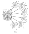
- the figure 4 represents a stack of six layers C1-C6 and the arrangement of the material M constituting the angular sectors (S i ) n of one layer (C) n to another.
- a first layer C1 comprises angular sectors (S i ) 1 comprising a woven material M comprising first fibers f1 and second oriented fibers f2 as defined above.
- the first fibers f1 of a first angular segment (S 1 ) 1 of the first layer (C) 1 are oriented in a first direction (d 11 ) 1 , the first direction (d 11 ) 1 forming an angle ( ⁇ 1 ) 1 with the radial direction d R of the first angular sector.
- the angle ( ⁇ 1 ) 1 is zero, in other words, the first fibers are oriented in the radial direction d R of the first angular sector (S 1 ) 1 .
- the first fibers f1 of a first angular sector (S 1 ) 2 of the second layer C 2 are oriented in a first direction (d 11 ) 2 , the first direction (d 11 ) 2 forming a second angle ( ⁇ 1 ) 2 with the first direction (d 11 ) 1 of the first sector (S 1 ) 1 of the first layer C 1 .
- the second angle ⁇ is equal to 60 °.
- the angular difference ⁇ is constant from one layer to another.
- the first fibers f1 of the first layer C 1 are oriented in the direction d radial R of the angular sector considered
- the first fibers f1 of the second layer C 2 are oriented in a direction forming a An angle of 60 ° with the radial direction d R
- the first fibers of the third layer are oriented in a direction forming an angle of 120 ° with the radial direction d R.
- the angular distance ⁇ is variable from one layer to another.
- the figure 5a represents the arrangement of the angular sectors (S i ) n as a function of the first angles in the center ( ⁇ i ) n .
- First sectors S A have an angle at the center ( ⁇ i + X) and second angular sectors S B have an angle at the center ( ⁇ i -X), the value of X being fixed beforehand.
- a layer C n alternately comprises a first angular sector S A and a second angular sector S B.
- the value of X is between 2 ° and 5 °.
- the figure 5b represents the arrangement of the angular sectors S A and S B on a first layer C n and a second layer C n + 1 successive.
- a first layer C n comprises first angular sectors S A with an angle in the center ( ⁇ + X) alternating with second angular sectors S B of central angle ( ⁇ -X).
- a second successive layer C n + 1 comprises an alternation of first sectors S A and second sectors S B.
- the angular sectors are arranged in such a way that a first angular sector S A of the layer C n covers a second angular sector S B of the successive layer C n + 1.
- the angular sectors (S i ) n may have random angles ⁇ i at the center, the angular sectors of a first layer (C) n at least partially covering the angular sectors of a second successive layer (C) n +1 .
- the antenna reflector developed according to one aspect of the invention has a mass less than 20% compared to a reflector developed using a "thick shell" technology, for example. This advantage is particularly interesting for applications on antennas positioned on the earth face of satellites. In this type of configuration, the reflectors are positioned on the upper part of the satellite, they are therefore subject to significant accelerations at launch.
- the reflector developed according to the proposed technology does not have cold bonding.
Abstract
Description
L'invention se situe dans le domaine des satellites de télécommunication comprenant des antennes passives équipées de réflecteurs. L'invention est particulièrement destinée pour des applications dans des bandes de très hautes fréquences de type Ka et Q/V mais répond aussi aux exigences techniques moindres de la bande de fréquences Ku.The invention is in the field of telecommunications satellites comprising passive antennas equipped with reflectors. The invention is particularly intended for applications in very high frequency bands Ka and Q / V but also meets the lower technical requirements of the Ku frequency band.
La bande de fréquences désignée Ku correspond aux fréquences comprises entre 12 et 18 GHz soit une longueur d'onde comprise entre 2,5 et 1,6 cm. La bande de fréquences désignée Ka correspond aux fréquences comprises entre 26,5 et 40 GHz soit une longueur d'onde comprise entre 11,3 et 7,5 mm.The frequency band designated Ku corresponds to the frequencies between 12 and 18 GHz, ie a wavelength of between 2.5 and 1.6 cm. The frequency band designated Ka corresponds to the frequencies between 26.5 and 40 GHz, ie a wavelength of between 11.3 and 7.5 mm.
La bande de fréquences désignée Q/V correspond aux fréquences comprises entre 33 et 75 GHz soit une longueur d'onde comprise entre 9, 1 et 3,3 mm.The frequency band designated Q / V corresponds to the frequencies between 33 and 75 GHz or a wavelength between 9, 1 and 3.3 mm.
Il existe une multitude d'application faisant intervenir les antennes à réflecteurs. Elles ont pour principal objectif d'atteindre des gains élevés en construisant des réflecteurs immenses, ce qui n'est envisageable que pour les radiotélescopes au sol.There is a multitude of applications involving reflector antennas. Their main objective is to achieve high gains by building huge reflectors, which is only feasible for ground radio telescopes.
Pour les satellites, les gains demandés sont moins importants (de l'ordre de 40 à 50 dB), mais la principale contrainte se situe au niveau de l'encombrement et de la masse à envoyer dans l'espace. En effet, il n'est pas possible de surdimensionner les réflecteurs pour améliorer le gain.For satellites, the gains requested are less important (of the order of 40 to 50 dB), but the main constraint is on the level of space and the mass to be sent into space. Indeed, it is not possible to oversize the reflectors to improve the gain.
Une des solutions consiste à utiliser le concept d'antenne de type grégorienne à deux réflecteurs positionnés en vis-à-vis et permettant d'obtenir dans un petit volume une antenne à focale équivalente plus importante.One solution is to use the concept of a Gregorian type antenna with two reflectors positioned vis-à-vis and to obtain in a small volume a larger equivalent focal length antenna.
Pour ce type d'antenne, les réflecteurs doivent :
- avoir un diamètre compris entre 250 et 1200 mm compatible avec un environnement spatial,
- présenter un profil réfléchissant fabriqué avec une très grande précision. Le défaut de fabrication d'une surface active peut être évalué à partir de la valeur RMS. La valeur RMS est la valeur moyenne des écarts type entre le profil de la surface élaborée et le profil de la surface théorique souhaitée. Les applications dans des bandes de fréquences Q/V nécessitent d'atteindre un RMS de l'ordre de 20 microns,
- afficher une grande stabilité du profil réfléchissant sur une large plage de température, allant de -200°C à +200C. Ceci impose l'utilisation de matériaux à faible coefficient de dilatation thermo élastique.
- être rigides, autrement dit, le premier mode de résonance doit être supérieur à une fréquence de 60Hz pour un type d'antenne défini.
- être de faibles poids, typiquement, une masse inférieure à 400 g pour un réflecteur de 500 mm de diamètre par exemple, et
- de mise en oeuvre facile de manière à limiter les coûts de production.
- have a diameter between 250 and 1200 mm compatible with a space environment,
- have a reflective profile manufactured with great precision. The manufacturing defect of an active surface can be evaluated from the RMS value. The RMS value is the average value of the standard deviations between the profile of the developed surface and the profile of the desired theoretical surface. Applications in Q / V frequency bands require an RMS of the order of 20 microns,
- display a high stability of the reflective profile over a wide temperature range, from -200 ° C to + 200C. This requires the use of materials with low coefficient of expansion thermo elastic.
- to be rigid, in other words, the first resonance mode must be greater than a frequency of 60Hz for a defined antenna type.
- be of low weight, typically a mass of less than 400 g for a reflector of 500 mm in diameter for example, and
- easy to implement in order to limit production costs.
Une première technologie classique dite technologie « coque épaisse » est largement répandue. Cette technologie repose sur une structure dite « sandwich ». Un réflecteur élaboré selon cette technologie comprend deux membranes ou peaux et un espaceur correspondant à une structure maintenant une position relative des membranes et assurant la rigidité de la structure « sandwich » ainsi formée. Pour les applications spatiales, les membranes sont généralement réalisées à base de renfort de carbone et l'espaceur est généralement de type « nid d'abeilles » ou CFRP (Carbon Fiber Renforced Polymer).A first conventional technology called "thick shell" technology is widespread. This technology is based on a structure called "sandwich". A reflector developed according to this technology comprises two membranes or skins and a spacer corresponding to a structure maintaining a relative position of the membranes and ensuring the rigidity of the "sandwich" structure thus formed. For space applications, the membranes are generally made of carbon reinforcement and the spacer is generally of the "honeycomb" or CFRP (Carbon Fiber Renforced Polymer) type.
Ce concept est particulièrement compétitif pour les réflecteurs dont le diamètre est compris entre 1 et 2 m, l'assemblage de ce type de structure est toutefois trop complexe et donc trop coûteux pour les réflecteurs de petit diamètre.This concept is particularly competitive for reflectors whose diameter is between 1 and 2 m, the assembly of this type of structure is however too complex and therefore too expensive for small diameter reflectors.
De plus, cette technologie requiert l'utilisation de grande quantité de colle, ce qui non compatible avec des applications à des températures élevées.In addition, this technology requires the use of a large amount of glue, which is not compatible with applications at high temperatures.
Par ailleurs, un réflecteur de diamètre 500 mm élaboré suivant la technologie dite « coque épaisse » pèse 550 g. Cette technologie ne permet pas d'atteindre les objectifs de poids fixés pour les applications dans un environnement spatial.In addition, a 500 mm diameter reflector developed according to the so-called "thick shell" technology weighs 550 g. This technology does not achieve the weight goals set for applications in a space environment.
Une deuxième technologie dite « métallique » est utilisée pour l'élaboration de réflecteurs de petit diamètre. Les réflecteurs sont classiquement réalisés par usinage. Cette technologie est économiquement intéressante.A second technology called "metallic" is used for the development of small diameter reflectors. The reflectors are conventionally made by machining. This technology is economically interesting.
Par contre, cette technologie est peu performante concernant les objectifs de poids. En effet, la masse d'un réflecteur principal de 500 mm diamètre comprenant un alliage de type Ta6V est d'environ 900 g, soit plus de deux fois les objectifs de poids souhaités pour des applications spatiales.On the other hand, this technology is not very efficient concerning the objectives of weight. Indeed, the mass of a 500 mm diameter main reflector comprising a Ta 6 V type alloy is about 900 g, more than twice the desired weight objectives for space applications.
Une troisième technologie dite « Isogrid » décrite dans la demande de brevet
Ce produit est un réflecteur comprenant une membrane sur laquelle est fixé un réseau de raidissage. Le réseau de raidissage est une grille de renfort formant un motif triangulaire dit « Isogrid » disposé de manière adjacente à la première structure, le réseau de raidissage étant fixé à la membrane par collage.This product is a reflector comprising a membrane on which is fixed a stiffening network. The stiffening network is a reinforcing grid forming a triangular pattern called "Isogrid" disposed adjacent to the first structure, the stiffening network being fixed to the membrane by gluing.
La complexité d'assemblage de la grille de renfort rend cette technologie peu performante économiquement pour les réflecteurs de petit diamètre, de la même manière que la technologie dite « coque épaisse ».The assembly complexity of the reinforcing grid makes this technology economically inefficient for small diameter reflectors, in the same way as the so-called "thick shell" technology.
Une quatrième technologie dite « technologie monolithique à raidisseur périphérique » permet de surmonter les problèmes liés au poids.A fourth technology called "monolithic technology with peripheral stiffener" overcomes the problems related to weight.
Cette technologie comprend une membrane monolithique sur laquelle une couronne de raidissage périphérique est collée. La couronne de raidissage est une nervure comprenant du carbone permettant de rigidifier le réflecteur et ainsi d'atteindre les objectifs de fréquence de résonance.This technology comprises a monolithic membrane on which a peripheral stiffening ring is glued. The stiffening ring is a rib comprising carbon to stiffen the reflector and thus achieve resonance frequency objectives.
Cette solution apporte une amélioration en terme de poids du réflecteur, toutefois le processus d'assemblage et de fabrication n'est pas optimisé.This solution provides an improvement in terms of weight of the reflector, however the assembly and manufacturing process is not optimized.
En effet, la réalisation d'un réflecteur selon cette technologie semble nécessiter la réalisation de deux moules distincts : un premier moule permettant la réalisation de la face active du réflecteur et un deuxième moule permettant la réalisation de la couronne de raidissage périphérique.Indeed, the realization of a reflector according to this technology seems to require the realization of two separate molds: a first mold for the realization of the active face of the reflector and a second mold for the realization of the peripheral stiffening ring.
D'autre part, le collage à froid de la couronne de raidissage périphérique sur la face active du réflecteur limite la gamme des températures d'utilisation.On the other hand, the cold bonding of the peripheral stiffening ring on the active face of the reflector limits the range of operating temperatures.
Un but de l'invention est d'élaborer un réflecteur d'antenne de télécommunication compatible avec des applications à hautes fréquences et adapté pour un environnement spatial et dont le processus d'élaboration nécessite peu de temps de main d'oeuvre.An object of the invention is to develop a telecommunication antenna reflector compatible with high frequency applications and adapted for a space environment and whose development process requires little manpower.
Selon un aspect de l'invention, il est proposé un réflecteur d'antenne compatible avec des applications à hautes fréquences comprises entre 12 et 75 GHz et adapté pour un environnement spatial géostationnaire de forme paraboloïdale ou ellipsoïdale comprenant une face réfléchissante permettant de focaliser un rayonnement électromagnétique. le réflecteur comprend une superposition d'au moins une couche comprenant un matériau composite fibré, caractérisé en ce qu'au moins une couche de matériau composite fibré comprend des secteurs angulaires disposés autour d'un centre, chacun des secteurs angulaires est défini par un premier angle au centre, et est orienté selon une direction radiale médiane de l'angle au centre, chacun des secteurs angulaires comprend le matériau composite fibré comprenant des premières fibres orientées dans une première direction et des deuxièmes fibres orientées dans une deuxième direction différente de la première direction, la première direction des premières fibres d'un secteur angulaire formant un deuxième angle avec la direction radiale du segment angulaire. Les secteurs angulaires comprennent trois zones concentriques : une zone centrale, une zone périphérique et une zone intermédiaire située entre la zone centrale et la zone périphérique, la zone intermédiaire formant un rebord.According to one aspect of the invention, there is provided an antenna reflector compatible with high frequency applications between 12 and 75 GHz and adapted for a paraboloidal or ellipsoidal geostationary space environment comprising a reflecting surface for focusing a radiation electromagnetic. the reflector comprises a superposition of at least one layer comprising a fiber composite material, characterized in that at least one layer of fiber composite material comprises angular sectors arranged around a center, each of the angular sectors is defined by a first angle at the center, and is oriented in a median radial direction of the angle at the center, each of the angular sectors comprises the fiber composite material comprising first fibers oriented in a first direction and second fibers oriented in a second direction different from the first direction, the first direction of the first fibers of an angular sector forming a second angle with the radial direction of the angular segment. The angular sectors comprise three concentric zones: a central zone, a peripheral zone and an intermediate zone located between the central zone and the peripheral zone, the intermediate zone forming a rim.
Avantageusement, le deuxième angle est compris entre 0 et 60°.Advantageously, the second angle is between 0 and 60 °.
L'utilisation d'un unique matériau composite fibré garantie de faibles déformations thermoplastiques.The use of a single fibered composite material guaranteed low thermoplastic deformations.
Le rebord formé à la périphérie de la surface active joue le rôle de couronne de raidissage directement intégrée dans le réflecteur évitant ainsi les inconvénients rencontrés dans la technologie dite « technologie monolithique à raidisseur périphérique » liés à la réalisation de moules et au collage à froid de la couronne sur la surface active. En effet, le réflecteur ainsi réalisé permet de limiter le nombre d'heures de main d'oeuvre nécessaires.The rim formed at the periphery of the active surface acts as a stiffening ring directly integrated in the reflector thus avoiding the disadvantages encountered in the so-called technology "monolithic technology with peripheral stiffener" related to the production of molds and the cold bonding of the crown on the active surface. In fact, the reflector thus produced makes it possible to limit the number of hours of labor required.
Avantageusement le réflecteur comprend au moins une couche possédant une partie centrale centrée sur le centre ce qui facilite l'assemblage des secteurs angulaires et évite que le chevauchement des segments angulaires au centre du réflecteurAdvantageously, the reflector comprises at least one layer having a central portion centered on the center which facilitates the assembly of the angular sectors and prevents the overlap of the angular segments in the center of the reflector
Selon un autre mode de réalisation de l'invention, il est proposé un réflecteur tel que décrit précédemment dans lequel l'écart angulaire entre le deuxième angle d'un premier secteur angulaire d'une première couche et le deuxième angle d'un premier secteur angulaire d'une deuxième couche successive est constant de manière à assurer une continuité mécanique entre des secteurs consécutifs.According to another embodiment of the invention, there is provided a reflector as described above wherein the angular difference between the second angle of a first angular sector of a first layer and the second angle of a first sector angle of a second successive layer is constant so as to ensure mechanical continuity between consecutive sectors.
Avantageusement, l'écart angulaire est compris entre 0°et 60°.Advantageously, the angular difference is between 0 ° and 60 °.
Avantageusement, l'empilement comprend entre 2 et 10 couches, et préférentiellement 6 couches. Cette valeur est un compromis entre le poids du réflecteur et la qualité géométrique du réflecteur.Advantageously, the stack comprises between 2 and 10 layers, and preferably 6 layers. This value is a compromise between the weight of the reflector and the geometric quality of the reflector.
Des premiers secteurs ont un angle au centre (αi + X) et des deuxièmes secteurs angulaires ont un angle au centre (αi -X), la valeur de X étant fixée préalablement. Une couche comprend alternativement un premier secteur angulaire puis un deuxième secteur angulaire.First sectors have an angle at the center (α i + X) and second angular sectors have an angle at the center (α i -X), the value of X being fixed beforehand. A layer alternately comprises a first angular sector and then a second angular sector.
Avantageusement, la valeur de X est comprise entre 2 ° et 5°.Advantageously, the value of X is between 2 ° and 5 °.
Les premiers secteurs angulaires d'une couche recouvrent les deuxièmes secteurs angulaires de la couche successive, de manière à assurer une continuité de la tenue mécanique entre secteurs consécutifs.The first angular sectors of a layer cover the second angular sectors of the successive layer, so as to ensure a continuity of the mechanical strength between consecutive sectors.
Réflecteur tel que décrit précédemment dans lequel la zone intermédiaire (Zi) forme un rebord de forme concave.Reflector as described above in which the intermediate zone (Zi) forms a concave rim.
Réflecteur tel que décrit précédemment lequel la direction de la zone périphérique (Zp) forme un troisième angle (γ) avec un axe vertical passant par les centres (c) des parties centrales (Pc) des couches [(C)n], le troisième angle (γ) étant compris entre 0 et 30°.Reflector as described above which the direction of the peripheral zone (Zp) forms a third angle (γ) with a vertical axis passing through the centers (c) of the central portions (Pc) of the layers [(C) n ], the third angle (γ) being between 0 and 30 °.
Les couches ont un diamètre compris entre 250 et 700 mm, et préférentiellement 500 mm.The layers have a diameter of between 250 and 700 mm, and preferably 500 mm.
Selon une variante de l'invention, le matériau composite tissé comprend un matériau fibré imprégné d'une résine thermodurcissable permettant au réflecteur d'atteindre des températures d'utilisation de 165°C.According to a variant of the invention, the woven composite material comprises a fiber material impregnated with a thermosetting resin allowing the reflector to reach operating temperatures of 165 ° C.
Selon une autre variante de l'invention, le matériau composite fibré comprend un matériau fibré imprégné d'une résine thermoplastique permettant d'atteindre des températures d'utilisation supérieures à 200°C.According to another variant of the invention, the fiber composite material comprises a fiber material impregnated with a thermoplastic resin making it possible to achieve operating temperatures greater than 200 ° C.
Préférentiellement, le matériau fibré est un tissu. Alternativement, le matériau fibré est de type NCF (ou non crimp Fabric).Preferably, the fiber material is a fabric. Alternatively, the fiber material is of the NCF (or non-crimp Fabric) type.
L'invention sera mieux comprise à l'étude de quelques modes de réalisation décrits à titre d'exemples nullement limitatifs, et illustrés par des dessins annexés sur lesquels :
- la
figure 1a représente un réflecteur, selon un aspect de l'invention, - la
figure 1b représente une superposition de couches constitutives du réflecteur, selon un aspect de l'invention, - la
figure 2 représente la structure d'une couche, selon un aspect de l'invention, - la
figure 3 illustre l'agencement et l'orientation du matériau fibré dans une couche du réflecteur, selon un aspect de l'invention, - La
figure 4 représente l'agencement relatif des secteurs comprenant le matériau fibré de l'ensemble des couches, selon un aspect de l'invention, et - les
figures 5a et 5b représente l'agencement des secteurs angulaires en fonction de l'angle au centre dans une couche et l'agencement des secteurs angulaires d'une couche à une autre, selon un aspect de l'invention.
- the
figure 1a represents a reflector, according to one aspect of the invention, - the
figure 1b represents a superposition of constituent layers of the reflector, according to one aspect of the invention, - the
figure 2 represents the structure of a layer, according to one aspect of the invention, - the
figure 3 illustrates the arrangement and orientation of the fiber material in a reflector layer, according to one aspect of the invention, - The
figure 4 represents the relative arrangement of the sectors comprising the fiber material of all the layers, according to one aspect of the invention, and - the
Figures 5a and 5b represents the arrangement of the angular sectors as a function of the center angle in a layer and the arrangement of the angular sectors from one layer to another, according to one aspect of the invention.
La
La surface concave de la couche constitue la surface réfléchissante du réflecteur R et est orientée vers le globe terrestre. Le rebord joue le rôle de couronne de raidissage permettant de rigidifier la structure et d'atteindre des fréquences de résonnances de 60 Hz à une température de 20°C.The concave surface of the layer constitutes the reflective surface of the reflector R and is oriented towards the terrestrial globe. The flange acts as a stiffening ring to stiffen the structure and reach resonance frequencies of 60 Hz at a temperature of 20 ° C.
La
La
Une couche Cn comprend une partie centrale PC et des secteurs angulaires (Si)n, les secteurs angulaires Si tronqués étant disposés autour de la partie centrale PC.A layer C n comprises a central portion P C and angular sectors (S i ) n , the truncated angular sectors S i being arranged around the central portion P C.
Dans une variante de l'invention, la couche peut comprendre un centre (c).In a variant of the invention, the layer may comprise a center (c).
Par ailleurs, la couche Cn comprend trois zones concentriques: une première zone Zc centrale, correspondant à la surface active du réflecteur, une deuxième zone Zp périphérique et une troisième zone Zi intermédiaire, la deuxième zone Zi intermédiaire formant un rebord.Moreover, the layer C n comprises three concentric zones: a first central zone Zc corresponding to the active surface of the reflector, a second zone Zp peripheral and a third zone Zi intermediate, the second zone Zi intermediate forming a rim.
La zone Zi intermédiaire est de forme concave de faible rayon de courbure, typiquement 5 mm de manière à limiter les effets de réflexions parasites des ondes électromagnétiques vers la source de l'antenne. Ce rayon ne peut être réduit davantage du fait de la faible capacité des tissus carbone à suivre sans se rompre des courbures de faible rayon.The intermediate zone Zi is of concave shape with a small radius of curvature, typically 5 mm so as to limit the effects of parasitic reflections of the electromagnetic waves towards the source of the antenna. This radius can not be reduced further because of the low capacity of carbon fabrics to follow without breaking small radii.
L'axe d'orientation de la zone Zp périphérique forme un angle γ avec un axe vertical passant par les centres des parties centrales PC des couches formant un raidisseur directement intégré à la structure du réflecteur permettant d'atteindre les objectifs de raideur fixés pour les applications de télécommunication à hautes fréquences.The axis of orientation of the peripheral zone Zp forms an angle γ with a vertical axis passing through the centers of the central portions P C of the layers forming a stiffener directly integrated into the reflector structure making it possible to reach the stiffness objectives set for high frequency telecommunications applications.
La
Préférentiellement, le concept de réflecteur proposé est compatible avec une utilisation d'un matériau M comprenant des fibres de carbone et une résine thermoplastique permettant d'atteindre une température d'utilisation supérieure à 200°C.Preferably, the proposed reflector concept is compatible with a use of a material M comprising carbon fibers and a thermoplastic resin making it possible to achieve a use temperature greater than 200 ° C.
Les secteurs angulaires (Si)n d'une couches Cn sont orientés selon une direction radiale dR du secteur angulaire (Si)n considéré.The angular sectors (S i ) n of a layer C n are oriented in a radial direction d R of the angular sector (S i ) n considered.
Un secteur angulaire (Si)n comprend un matériau M fibré thermoplastique comprenant des premières fibres f1 et des deuxièmes fibres f2. Les premières fibres f1 sont orientées selon une première direction (di1)n, i étant un indice correspondant au secteur considéré et n étant un indice correspondant à la couche considérée, les deuxièmes fibres f2 étant orientées selon une direction (di2)n, différente de la première direction (di1)n. Un deuxième angle (βi)n est défini comme l'écart angulaire entre la première direction (di1)n et la direction dR radiale du secteur angulaire.An angular sector (S i ) n comprises a thermoplastic fiber material M comprising first fibers f1 and second fibers f2. The first fibers f1 are oriented in a first direction (d i1 ) n , i being an index corresponding to the sector considered and n being an index corresponding to the layer considered, the second fibers f2 being oriented in a direction (d i2 ) n , different from the first direction (d i1 ) n . A second angle (β i ) n is defined as the angular difference between the first direction (d i1 ) n and the radial direction d R of the angular sector.
Le deuxième angle (βi)n est compris entre 0° et 180°, en l'espèce, le deuxième angle (βi)n est égal à 60° pour tous les secteurs angulaires de la première couche C1.The second angle (β i ) n is between 0 ° and 180 °, in this case the second angle (β i ) n is equal to 60 ° for all the angular sectors of the first layer C1.
Lorsque le deuxième angle (βi)n est égal à 0°, les premières fibres f1 du matériau M tissé sont orientées selon la direction dR radiale du secteur angulaire (Si)n considéré.When the second angle (β i ) n is equal to 0 °, the first fibers f1 of the woven material M are oriented in the direction d radial R of the angular sector (S i ) n considered.
La
Une première couches C1 comprend des secteurs angulaires (Si)1 comprenant un matériau M tissé comprenant des premières fibres f1 et des deuxièmes fibres f2 orientées telles que défini précédemment.A first layer C1 comprises angular sectors (S i ) 1 comprising a woven material M comprising first fibers f1 and second oriented fibers f2 as defined above.
Les premières fibres f1 d'un premier segment angulaire (S1)1 de la première couche (C)1 sont orientées selon une première direction (d11)1, la première direction (d11)1 formant un angle (β1)1 avec la direction radiale dR du premier secteur angulaire. En l'espèce, l'angle (β1)1 est nul, autrement dit, les premières fibres sont orientées selon la direction radiale dR du premier secteur angulaire (S1)1.The first fibers f1 of a first angular segment (S 1 ) 1 of the first layer (C) 1 are oriented in a first direction (d 11 ) 1 , the first direction (d 11 ) 1 forming an angle (β 1 ) 1 with the radial direction d R of the first angular sector. In this case, the angle (β 1 ) 1 is zero, in other words, the first fibers are oriented in the radial direction d R of the first angular sector (S 1 ) 1 .
Les premières fibres f1 d'un premier secteur angulaire (S1)2 de la deuxième couche C2 sont orientées selon une première direction (d11)2, la première direction (d11)2 formant un deuxième angle (β1)2 avec la première direction (d11)1 du premier secteur (S1)1 de la première couche C1. En l'espèce, le deuxième angle β est égal à 60°.The first fibers f1 of a first angular sector (S 1 ) 2 of the second layer C 2 are oriented in a first direction (d 11 ) 2 , the first direction (d 11 ) 2 forming a second angle (β 1 ) 2 with the first direction (d 11 ) 1 of the first sector (S 1 ) 1 of the first layer C 1 . In this case, the second angle β is equal to 60 °.
L'écart angulaire θ correspond à la différence d'angle entre la direction (d11)2 des premières fibres f1 du premier secteur angulaire (S1)2 de la deuxième couche C2 et la direction (d11)1 des premières fibres f1 du premier secteur (S1)2 de la première coucheC1, autrement dit θ=(β1)2-(β1)1. En l'espèce, l'écart angulaire θ est constant d'une couche à une autre.The angular difference θ corresponds to the difference in angle between the direction (d 11 ) 2 of the
Ainsi, les premières fibres f1 de la première couche C1 sont orientées selon la direction dR radiale du secteur angulaire considéré, les premières fibres f1 de la deuxième couche C2 sont orientées selon une direction formant un angle de 60° avec la direction dR radiale, les premières fibres de la troisième couche sont orientées selon une direction formant un angle de 120° avec la direction dR radiale.Thus, the first fibers f1 of the first layer C 1 are oriented in the direction d radial R of the angular sector considered, the first fibers f1 of the second layer C 2 are oriented in a direction forming a An angle of 60 ° with the radial direction d R , the first fibers of the third layer are oriented in a direction forming an angle of 120 ° with the radial direction d R.
Selon une variante de l'invention, l'écart angulaire θ est variable d'une couche à une autre.According to a variant of the invention, the angular distance θ is variable from one layer to another.
La
Des premiers secteurs SA ont un angle au centre (αi + X) et des deuxièmes secteurs angulaires SB ont un angle au centre (αi -X), la valeur de X étant fixée préalablement. Une couche Cn comprend alternativement un premier secteur angulaire SA puis un deuxième secteur angulaire SB. Avantageusement, la valeur de X est comprise entre 2° et 5°.First sectors S A have an angle at the center (α i + X) and second angular sectors S B have an angle at the center (α i -X), the value of X being fixed beforehand. A layer C n alternately comprises a first angular sector S A and a second angular sector S B. Advantageously, the value of X is between 2 ° and 5 °.
La
Une première couche Cn comprend des premiers secteurs angulaires SA d'angle au centre (α+X) en alternance avec des deuxièmes secteurs angulaires SB d'angle au centre (α-X). Une deuxième couche Cn+1 successive comprend une alternance de premiers secteurs SA et de deuxièmes secteurs SB. Les secteurs angulaires sont disposés de manière à ce qu'un premier secteur angulaire SA de la couche Cn recouvre un deuxième secteur angulaire SB de la couche successive Cn+1. En variante, les secteurs angulaires (Si)n peuvent avoir des angles au centre αi aléatoires, les secteurs angulaires d'une première couche (C)n recouvrant au moins partiellement les secteurs angulaires d'une deuxième couche successive (C)n+1. Le réflecteur d'antenne élaboré selon un aspect de l'invention a une masse inférieure de 20% par rapport à un réflecteur élaboré selon une technologie « coque épaisse », par exemple. Cet avantage est particulièrement intéressant pour les applications sur des antennes positionnées sur la face terre des satellites. Dans ce type de configuration, les réflecteurs sont positionnés sur la partie haute du satellite, ils sont donc soumis à d'importantes accélérations lors du lancement.A first layer C n comprises first angular sectors S A with an angle in the center (α + X) alternating with second angular sectors S B of central angle (α-X). A second successive layer C n + 1 comprises an alternation of first sectors S A and second sectors S B. The angular sectors are arranged in such a way that a first angular sector S A of the layer C n covers a second angular sector S B of the successive layer C n + 1. As a variant, the angular sectors (S i ) n may have random angles α i at the center, the angular sectors of a first layer (C) n at least partially covering the angular sectors of a second successive layer (C) n +1 . The antenna reflector developed according to one aspect of the invention has a mass less than 20% compared to a reflector developed using a "thick shell" technology, for example. This advantage is particularly interesting for applications on antennas positioned on the earth face of satellites. In this type of configuration, the reflectors are positioned on the upper part of the satellite, they are therefore subject to significant accelerations at launch.
De plus, le réflecteur élaboré selon la technologie proposée ne présente pas de collage à froid.In addition, the reflector developed according to the proposed technology does not have cold bonding.
Claims (15)
Applications Claiming Priority (1)
| Application Number | Priority Date | Filing Date | Title |
|---|---|---|---|
| FR1201995A FR2993414B1 (en) | 2012-07-13 | 2012-07-13 | TELECOMMUNICATION ANTENNA REFLECTOR FOR HIGH FREQUENCY APPLICATION IN A GEOSTATIONARY SPATIAL ENVIRONMENT |
Publications (2)
| Publication Number | Publication Date |
|---|---|
| EP2685560A1 true EP2685560A1 (en) | 2014-01-15 |
| EP2685560B1 EP2685560B1 (en) | 2019-08-21 |
Family
ID=47172694
Family Applications (1)
| Application Number | Title | Priority Date | Filing Date |
|---|---|---|---|
| EP13176211.4A Active EP2685560B1 (en) | 2012-07-13 | 2013-07-11 | Telecommunication antenna reflector for high-frequency applications in a geostationary space environment |
Country Status (4)
| Country | Link |
|---|---|
| US (1) | US9673535B2 (en) |
| EP (1) | EP2685560B1 (en) |
| ES (1) | ES2753969T3 (en) |
| FR (1) | FR2993414B1 (en) |
Families Citing this family (1)
| Publication number | Priority date | Publication date | Assignee | Title |
|---|---|---|---|---|
| US11088461B1 (en) * | 2020-10-12 | 2021-08-10 | Custom Microwave Inc. | Quad band petal reflector antenna |
Citations (5)
| Publication number | Priority date | Publication date | Assignee | Title |
|---|---|---|---|---|
| FR2294820A1 (en) * | 1974-12-21 | 1976-07-16 | Messerschmitt Boelkow Blohm | LIGHTWEIGHT THIN PLASTIC CONSTRUCTION ELEMENT REINFORCED WITH CARBON FIBERS |
| US4242686A (en) * | 1978-04-24 | 1980-12-30 | General Dynamics Corporation, Pomona Division | Three-dimensionally curved, knit wire electromagnetic wave reflector |
| US5488383A (en) * | 1994-01-21 | 1996-01-30 | Lockheed Missiles & Space Co., Inc. | Method for accurizing mesh fabric reflector panels of a deployable reflector |
| EP0948085A2 (en) | 1998-04-01 | 1999-10-06 | TRW Inc. | Composite isogrid structures for parabolic surfaces |
| US20070069970A1 (en) * | 2005-09-26 | 2007-03-29 | Gideon Argaman | Low wind load parabolic dish antenna fed by crosspolarized printed dipoles |
Family Cites Families (3)
| Publication number | Priority date | Publication date | Assignee | Title |
|---|---|---|---|---|
| US5686930A (en) * | 1994-01-31 | 1997-11-11 | Brydon; Louis B. | Ultra lightweight thin membrane antenna reflector |
| FR2944154B1 (en) * | 2009-04-02 | 2016-05-06 | Astrium Sas | RADIOELECTRIC ANTENNA HAVING IMPROVED RIGIDIFICATION MEANS |
| US9350083B2 (en) * | 2012-03-10 | 2016-05-24 | Harris Corporation | Portable satellite communication system |
-
2012
- 2012-07-13 FR FR1201995A patent/FR2993414B1/en active Active
-
2013
- 2013-07-11 EP EP13176211.4A patent/EP2685560B1/en active Active
- 2013-07-11 ES ES13176211T patent/ES2753969T3/en active Active
- 2013-07-12 US US13/941,410 patent/US9673535B2/en active Active
Patent Citations (5)
| Publication number | Priority date | Publication date | Assignee | Title |
|---|---|---|---|---|
| FR2294820A1 (en) * | 1974-12-21 | 1976-07-16 | Messerschmitt Boelkow Blohm | LIGHTWEIGHT THIN PLASTIC CONSTRUCTION ELEMENT REINFORCED WITH CARBON FIBERS |
| US4242686A (en) * | 1978-04-24 | 1980-12-30 | General Dynamics Corporation, Pomona Division | Three-dimensionally curved, knit wire electromagnetic wave reflector |
| US5488383A (en) * | 1994-01-21 | 1996-01-30 | Lockheed Missiles & Space Co., Inc. | Method for accurizing mesh fabric reflector panels of a deployable reflector |
| EP0948085A2 (en) | 1998-04-01 | 1999-10-06 | TRW Inc. | Composite isogrid structures for parabolic surfaces |
| US20070069970A1 (en) * | 2005-09-26 | 2007-03-29 | Gideon Argaman | Low wind load parabolic dish antenna fed by crosspolarized printed dipoles |
Also Published As
| Publication number | Publication date |
|---|---|
| ES2753969T3 (en) | 2020-04-15 |
| US20140015735A1 (en) | 2014-01-16 |
| FR2993414A1 (en) | 2014-01-17 |
| FR2993414B1 (en) | 2014-08-22 |
| US9673535B2 (en) | 2017-06-06 |
| EP2685560B1 (en) | 2019-08-21 |
Similar Documents
| Publication | Publication Date | Title |
|---|---|---|
| FR2550663A1 (en) | ELECTROMAGNETIC RADIATION REFLECTOR STRUCTURE | |
| EP2185345B1 (en) | Structural frame of a composite material and aircraft fuselage including such frame | |
| EP0519775A1 (en) | In service reconfigurable antenna reflector | |
| EP2808943B1 (en) | Method for producing an antenna reflector with formed surface, reflector with formed surface obtained by said method and antenna comprising such a reflector | |
| JP5330538B2 (en) | Broadband parabolic antenna radar dome | |
| EP2648281B1 (en) | Reconfigurable antenna reflector | |
| EP2362489B1 (en) | Deformable reflecting membrane for a reconfigurable reflector, reconfigurable antenna reflector and antenna comprising such a membrane | |
| EP2685560B1 (en) | Telecommunication antenna reflector for high-frequency applications in a geostationary space environment | |
| EP2690709A1 (en) | Antenna reflector, of diameter greater than 1 m, for high-frequency applications in a space environment | |
| CA2500990C (en) | 3-d reflector antenna for forming beams in different frequency bands | |
| FR2944155A1 (en) | RADIOELECTRONIC ANTENNA WITH IMPROVED DECOUPLING CORNERS | |
| EP0466579B1 (en) | Double reflector with grids | |
| FR3077270A1 (en) | FOLDABLE / DEPLOYABLE DEVICE COMPRISING AT LEAST FOUR LEFT SECTIONS CONNECTED BY HINGES | |
| FR2944154A1 (en) | RADIOELECTRIC ANTENNA HAVING IMPROVED RIGIDIFICATION MEANS | |
| US20230291095A1 (en) | Environmentally robust fabric radome for planar mmwave beam-steering antennas | |
| GB2616480A (en) | Environmentally Robust Fabric Radome for Planar mmWave Beam-steering Antennas | |
| FR2731846A1 (en) | WALL FOR RADOMES AND RADOMES SO OBTAINED | |
| FR2502852A1 (en) | Large receiving antenna for satellite communications - comprises several panels of sandwich of synthetic materials with metallised skins and contains heating elements for de-icing | |
| FR2579374A1 (en) | Device for supporting and/or reinforcing a surface element, in particular the convex rear face of an antenna reflector | |
| JPH11239019A (en) | Antenna system | |
| FR2902934A1 (en) | Airborne radome wall for radio detection and ranging of e.g. aircraft, has films made of resin and introduced in pores, where resin flows towards pores to fill pores during pressure of tissue layer on core and upper skin on tissue layer |
Legal Events
| Date | Code | Title | Description |
|---|---|---|---|
| PUAI | Public reference made under article 153(3) epc to a published international application that has entered the european phase |
Free format text: ORIGINAL CODE: 0009012 |
|
| AK | Designated contracting states |
Kind code of ref document: A1 Designated state(s): AL AT BE BG CH CY CZ DE DK EE ES FI FR GB GR HR HU IE IS IT LI LT LU LV MC MK MT NL NO PL PT RO RS SE SI SK SM TR |
|
| AX | Request for extension of the european patent |
Extension state: BA ME |
|
| 17P | Request for examination filed |
Effective date: 20140711 |
|
| RBV | Designated contracting states (corrected) |
Designated state(s): AL AT BE BG CH CY CZ DE DK EE ES FI FR GB GR HR HU IE IS IT LI LT LU LV MC MK MT NL NO PL PT RO RS SE SI SK SM TR |
|
| STAA | Information on the status of an ep patent application or granted ep patent |
Free format text: STATUS: EXAMINATION IS IN PROGRESS |
|
| 17Q | First examination report despatched |
Effective date: 20180927 |
|
| GRAP | Despatch of communication of intention to grant a patent |
Free format text: ORIGINAL CODE: EPIDOSNIGR1 |
|
| STAA | Information on the status of an ep patent application or granted ep patent |
Free format text: STATUS: GRANT OF PATENT IS INTENDED |
|
| RIC1 | Information provided on ipc code assigned before grant |
Ipc: H01Q 15/16 20060101AFI20190306BHEP Ipc: H01Q 15/14 20060101ALI20190306BHEP Ipc: H01Q 1/28 20060101ALI20190306BHEP |
|
| INTG | Intention to grant announced |
Effective date: 20190403 |
|
| GRAS | Grant fee paid |
Free format text: ORIGINAL CODE: EPIDOSNIGR3 |
|
| GRAA | (expected) grant |
Free format text: ORIGINAL CODE: 0009210 |
|
| STAA | Information on the status of an ep patent application or granted ep patent |
Free format text: STATUS: THE PATENT HAS BEEN GRANTED |
|
| RAP1 | Party data changed (applicant data changed or rights of an application transferred) |
Owner name: THALES |
|
| AK | Designated contracting states |
Kind code of ref document: B1 Designated state(s): AL AT BE BG CH CY CZ DE DK EE ES FI FR GB GR HR HU IE IS IT LI LT LU LV MC MK MT NL NO PL PT RO RS SE SI SK SM TR |
|
| REG | Reference to a national code |
Ref country code: GB Ref legal event code: FG4D Free format text: NOT ENGLISH |
|
| REG | Reference to a national code |
Ref country code: CH Ref legal event code: EP |
|
| REG | Reference to a national code |
Ref country code: DE Ref legal event code: R096 Ref document number: 602013059384 Country of ref document: DE |
|
| REG | Reference to a national code |
Ref country code: AT Ref legal event code: REF Ref document number: 1170806 Country of ref document: AT Kind code of ref document: T Effective date: 20190915 |
|
| REG | Reference to a national code |
Ref country code: IE Ref legal event code: FG4D Free format text: LANGUAGE OF EP DOCUMENT: FRENCH |
|
| REG | Reference to a national code |
Ref country code: SE Ref legal event code: TRGR |
|
| REG | Reference to a national code |
Ref country code: LT Ref legal event code: MG4D |
|
| REG | Reference to a national code |
Ref country code: NL Ref legal event code: MP Effective date: 20190821 |
|
| PG25 | Lapsed in a contracting state [announced via postgrant information from national office to epo] |
Ref country code: FI Free format text: LAPSE BECAUSE OF FAILURE TO SUBMIT A TRANSLATION OF THE DESCRIPTION OR TO PAY THE FEE WITHIN THE PRESCRIBED TIME-LIMIT Effective date: 20190821 Ref country code: LT Free format text: LAPSE BECAUSE OF FAILURE TO SUBMIT A TRANSLATION OF THE DESCRIPTION OR TO PAY THE FEE WITHIN THE PRESCRIBED TIME-LIMIT Effective date: 20190821 Ref country code: HR Free format text: LAPSE BECAUSE OF FAILURE TO SUBMIT A TRANSLATION OF THE DESCRIPTION OR TO PAY THE FEE WITHIN THE PRESCRIBED TIME-LIMIT Effective date: 20190821 Ref country code: NL Free format text: LAPSE BECAUSE OF FAILURE TO SUBMIT A TRANSLATION OF THE DESCRIPTION OR TO PAY THE FEE WITHIN THE PRESCRIBED TIME-LIMIT Effective date: 20190821 Ref country code: NO Free format text: LAPSE BECAUSE OF FAILURE TO SUBMIT A TRANSLATION OF THE DESCRIPTION OR TO PAY THE FEE WITHIN THE PRESCRIBED TIME-LIMIT Effective date: 20191121 Ref country code: BG Free format text: LAPSE BECAUSE OF FAILURE TO SUBMIT A TRANSLATION OF THE DESCRIPTION OR TO PAY THE FEE WITHIN THE PRESCRIBED TIME-LIMIT Effective date: 20191121 Ref country code: PT Free format text: LAPSE BECAUSE OF FAILURE TO SUBMIT A TRANSLATION OF THE DESCRIPTION OR TO PAY THE FEE WITHIN THE PRESCRIBED TIME-LIMIT Effective date: 20191223 |
|
| PG25 | Lapsed in a contracting state [announced via postgrant information from national office to epo] |
Ref country code: IS Free format text: LAPSE BECAUSE OF FAILURE TO SUBMIT A TRANSLATION OF THE DESCRIPTION OR TO PAY THE FEE WITHIN THE PRESCRIBED TIME-LIMIT Effective date: 20191221 Ref country code: GR Free format text: LAPSE BECAUSE OF FAILURE TO SUBMIT A TRANSLATION OF THE DESCRIPTION OR TO PAY THE FEE WITHIN THE PRESCRIBED TIME-LIMIT Effective date: 20191122 Ref country code: RS Free format text: LAPSE BECAUSE OF FAILURE TO SUBMIT A TRANSLATION OF THE DESCRIPTION OR TO PAY THE FEE WITHIN THE PRESCRIBED TIME-LIMIT Effective date: 20190821 Ref country code: AL Free format text: LAPSE BECAUSE OF FAILURE TO SUBMIT A TRANSLATION OF THE DESCRIPTION OR TO PAY THE FEE WITHIN THE PRESCRIBED TIME-LIMIT Effective date: 20190821 Ref country code: LV Free format text: LAPSE BECAUSE OF FAILURE TO SUBMIT A TRANSLATION OF THE DESCRIPTION OR TO PAY THE FEE WITHIN THE PRESCRIBED TIME-LIMIT Effective date: 20190821 |
|
| REG | Reference to a national code |
Ref country code: AT Ref legal event code: MK05 Ref document number: 1170806 Country of ref document: AT Kind code of ref document: T Effective date: 20190821 |
|
| PG25 | Lapsed in a contracting state [announced via postgrant information from national office to epo] |
Ref country code: TR Free format text: LAPSE BECAUSE OF FAILURE TO SUBMIT A TRANSLATION OF THE DESCRIPTION OR TO PAY THE FEE WITHIN THE PRESCRIBED TIME-LIMIT Effective date: 20190821 |
|
| REG | Reference to a national code |
Ref country code: ES Ref legal event code: FG2A Ref document number: 2753969 Country of ref document: ES Kind code of ref document: T3 Effective date: 20200415 |
|
| PG25 | Lapsed in a contracting state [announced via postgrant information from national office to epo] |
Ref country code: RO Free format text: LAPSE BECAUSE OF FAILURE TO SUBMIT A TRANSLATION OF THE DESCRIPTION OR TO PAY THE FEE WITHIN THE PRESCRIBED TIME-LIMIT Effective date: 20190821 Ref country code: DK Free format text: LAPSE BECAUSE OF FAILURE TO SUBMIT A TRANSLATION OF THE DESCRIPTION OR TO PAY THE FEE WITHIN THE PRESCRIBED TIME-LIMIT Effective date: 20190821 Ref country code: EE Free format text: LAPSE BECAUSE OF FAILURE TO SUBMIT A TRANSLATION OF THE DESCRIPTION OR TO PAY THE FEE WITHIN THE PRESCRIBED TIME-LIMIT Effective date: 20190821 Ref country code: AT Free format text: LAPSE BECAUSE OF FAILURE TO SUBMIT A TRANSLATION OF THE DESCRIPTION OR TO PAY THE FEE WITHIN THE PRESCRIBED TIME-LIMIT Effective date: 20190821 Ref country code: PL Free format text: LAPSE BECAUSE OF FAILURE TO SUBMIT A TRANSLATION OF THE DESCRIPTION OR TO PAY THE FEE WITHIN THE PRESCRIBED TIME-LIMIT Effective date: 20190821 |
|
| PG25 | Lapsed in a contracting state [announced via postgrant information from national office to epo] |
Ref country code: SM Free format text: LAPSE BECAUSE OF FAILURE TO SUBMIT A TRANSLATION OF THE DESCRIPTION OR TO PAY THE FEE WITHIN THE PRESCRIBED TIME-LIMIT Effective date: 20190821 Ref country code: IS Free format text: LAPSE BECAUSE OF FAILURE TO SUBMIT A TRANSLATION OF THE DESCRIPTION OR TO PAY THE FEE WITHIN THE PRESCRIBED TIME-LIMIT Effective date: 20200224 Ref country code: SK Free format text: LAPSE BECAUSE OF FAILURE TO SUBMIT A TRANSLATION OF THE DESCRIPTION OR TO PAY THE FEE WITHIN THE PRESCRIBED TIME-LIMIT Effective date: 20190821 Ref country code: CZ Free format text: LAPSE BECAUSE OF FAILURE TO SUBMIT A TRANSLATION OF THE DESCRIPTION OR TO PAY THE FEE WITHIN THE PRESCRIBED TIME-LIMIT Effective date: 20190821 |
|
| REG | Reference to a national code |
Ref country code: DE Ref legal event code: R097 Ref document number: 602013059384 Country of ref document: DE |
|
| PLBE | No opposition filed within time limit |
Free format text: ORIGINAL CODE: 0009261 |
|
| STAA | Information on the status of an ep patent application or granted ep patent |
Free format text: STATUS: NO OPPOSITION FILED WITHIN TIME LIMIT |
|
| PG2D | Information on lapse in contracting state deleted |
Ref country code: IS |
|
| 26N | No opposition filed |
Effective date: 20200603 |
|
| PG25 | Lapsed in a contracting state [announced via postgrant information from national office to epo] |
Ref country code: SI Free format text: LAPSE BECAUSE OF FAILURE TO SUBMIT A TRANSLATION OF THE DESCRIPTION OR TO PAY THE FEE WITHIN THE PRESCRIBED TIME-LIMIT Effective date: 20190821 |
|
| PG25 | Lapsed in a contracting state [announced via postgrant information from national office to epo] |
Ref country code: MC Free format text: LAPSE BECAUSE OF FAILURE TO SUBMIT A TRANSLATION OF THE DESCRIPTION OR TO PAY THE FEE WITHIN THE PRESCRIBED TIME-LIMIT Effective date: 20190821 |
|
| REG | Reference to a national code |
Ref country code: CH Ref legal event code: PL |
|
| REG | Reference to a national code |
Ref country code: BE Ref legal event code: MM Effective date: 20200731 |
|
| PG25 | Lapsed in a contracting state [announced via postgrant information from national office to epo] |
Ref country code: LU Free format text: LAPSE BECAUSE OF NON-PAYMENT OF DUE FEES Effective date: 20200711 Ref country code: LI Free format text: LAPSE BECAUSE OF NON-PAYMENT OF DUE FEES Effective date: 20200731 Ref country code: CH Free format text: LAPSE BECAUSE OF NON-PAYMENT OF DUE FEES Effective date: 20200731 |
|
| PG25 | Lapsed in a contracting state [announced via postgrant information from national office to epo] |
Ref country code: BE Free format text: LAPSE BECAUSE OF NON-PAYMENT OF DUE FEES Effective date: 20200731 |
|
| PG25 | Lapsed in a contracting state [announced via postgrant information from national office to epo] |
Ref country code: IE Free format text: LAPSE BECAUSE OF NON-PAYMENT OF DUE FEES Effective date: 20200711 |
|
| PG25 | Lapsed in a contracting state [announced via postgrant information from national office to epo] |
Ref country code: MT Free format text: LAPSE BECAUSE OF FAILURE TO SUBMIT A TRANSLATION OF THE DESCRIPTION OR TO PAY THE FEE WITHIN THE PRESCRIBED TIME-LIMIT Effective date: 20190821 Ref country code: CY Free format text: LAPSE BECAUSE OF FAILURE TO SUBMIT A TRANSLATION OF THE DESCRIPTION OR TO PAY THE FEE WITHIN THE PRESCRIBED TIME-LIMIT Effective date: 20190821 |
|
| PG25 | Lapsed in a contracting state [announced via postgrant information from national office to epo] |
Ref country code: MK Free format text: LAPSE BECAUSE OF FAILURE TO SUBMIT A TRANSLATION OF THE DESCRIPTION OR TO PAY THE FEE WITHIN THE PRESCRIBED TIME-LIMIT Effective date: 20190821 |
|
| PGFP | Annual fee paid to national office [announced via postgrant information from national office to epo] |
Ref country code: FR Payment date: 20230622 Year of fee payment: 11 |
|
| PGFP | Annual fee paid to national office [announced via postgrant information from national office to epo] |
Ref country code: SE Payment date: 20230626 Year of fee payment: 11 |
|
| PGFP | Annual fee paid to national office [announced via postgrant information from national office to epo] |
Ref country code: IT Payment date: 20230627 Year of fee payment: 11 Ref country code: GB Payment date: 20230615 Year of fee payment: 11 Ref country code: ES Payment date: 20230810 Year of fee payment: 11 |
|
| PGFP | Annual fee paid to national office [announced via postgrant information from national office to epo] |
Ref country code: DE Payment date: 20230613 Year of fee payment: 11 |