EP2362489B1 - Deformable reflecting membrane for a reconfigurable reflector, reconfigurable antenna reflector and antenna comprising such a membrane - Google Patents
Deformable reflecting membrane for a reconfigurable reflector, reconfigurable antenna reflector and antenna comprising such a membrane Download PDFInfo
- Publication number
- EP2362489B1 EP2362489B1 EP11155056A EP11155056A EP2362489B1 EP 2362489 B1 EP2362489 B1 EP 2362489B1 EP 11155056 A EP11155056 A EP 11155056A EP 11155056 A EP11155056 A EP 11155056A EP 2362489 B1 EP2362489 B1 EP 2362489B1
- Authority
- EP
- European Patent Office
- Prior art keywords
- membrane
- reflector
- patches
- reflective membrane
- deformable reflective
- Prior art date
- Legal status (The legal status is an assumption and is not a legal conclusion. Google has not performed a legal analysis and makes no representation as to the accuracy of the status listed.)
- Not-in-force
Links
Images


Classifications
-
- H—ELECTRICITY
- H01—ELECTRIC ELEMENTS
- H01Q—ANTENNAS, i.e. RADIO AERIALS
- H01Q15/00—Devices for reflection, refraction, diffraction or polarisation of waves radiated from an antenna, e.g. quasi-optical devices
- H01Q15/14—Reflecting surfaces; Equivalent structures
- H01Q15/147—Reflecting surfaces; Equivalent structures provided with means for controlling or monitoring the shape of the reflecting surface
Definitions
- the present invention relates to a deformable reflective membrane for a reconfigurable reflector, a reconfigurable reflector comprising such a membrane and an antenna comprising such a reflector. It applies to any antenna reflector which one wishes to be able to modify the shape of the beam in service and more particularly to the field of the space applications such as the telecommunications by satellite.
- a conventional method for obtaining a shaped contour beam is to use a multiple source illuminating, according to a suitable illumination law, a single or double eccentric reflector system, or even a multiple source direct radiation.
- the radiating elements of the source are excited with signals whose phases and amplitudes are optimized by means of a BFN (Beam Forming Network) beam forming network comprising a plurality of waveguides.
- BFN Beam Forming Network
- this type of antenna called a network antenna, is very complex and has losses of radio-electric energy and a large penalty for a satellite implantation.
- a single source associated with a single or double reflector system with a formed surface that is to say having a specific geometry defining the an area with a non-circular contour, for example a country or group of countries.
- the optical path variations between the source and different points of the reflector make it possible to generate beams having a phase and amplitude diagram corresponding to the characteristics of the desired radiation pattern.
- Another type of known reflecting surface consists in using a grid of orthogonal stiff wires whose edges are free, the grid being maintained and constrained to a predetermined shape only by points. control.
- a model was constructed using 0.3mm diameter piano string wires and a distance between each 10mm string for a 30cm reflector diameter. Nine control points have deformed the surface.
- the radiofrequency reflectivity of this reflecting surface is insufficient in Ku-band and the contacts between each wire of the gate are potential sources of unacceptable intermodulation products.
- the object of the invention is to overcome the drawbacks of known deformable reflective surfaces and to provide a deformable reflective membrane with high radiofrequency reflectivity having a high elastic zone allowing large deformations in multiple directions in the plane and out of the plane of the surface of the membrane, having a flexural stiffness and a low coefficient of thermal expansion allowing a dimensional stability of the membrane over a temperature range compatible with a spatial application, and good electrical homogeneity or electrical contacts isolated from each other for do not create significant levels of intermodulation products.
- the invention relates to a deformable reflective membrane for reconfigurable reflector, characterized in that it comprises in thickness, an alternating superposition of layers of conductive elastomer and at least two discontinuous reinforcing layers, each reinforcing layer being cut in elementary patches spaced from each other and periodically distributed in the plane of the membrane.
- the elementary reinforcing patches are staggered from one layer to another.
- the number of reinforcement layers is even.
- the distribution of reinforcement patches in the different reinforcement layers has a mirror symmetry with respect to the plane of the reinforcing layer located in the center of the membrane.
- the reinforcing layer is made of a material with a low coefficient of thermal expansion, such as fibers made of iron and nickel alloy, for example Invar, or carbon fibers.
- the constituents of the reinforcing layer may also be stainless steel or tungsten fibers or any other material having identical properties
- the conductive elastomer is an elastomer loaded with metal particles and has an electrical conductivity of between 2.10 -3 ⁇ / cm and 5.10 -3 ⁇ / cm.
- the conductive elastomer may comprise 30% silicone and 70% metal particles.
- the invention also relates to a reconfigurable antenna reflector and an antenna comprising such a deformable reflective membrane.
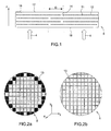
- the portion of membrane 5 shown on the figure 1 comprises in thickness along the Z axis, an alternating superposition of layers of conductive elastomer 10 and reinforcing layers 11, the reinforcing layers being non-homogeneous in the XY plane of the layer.
- the reinforcing layers 11 are discontinuous and consist of elementary patches 13 spaced from each other and periodically distributed in the plane of the membrane.
- the patches 13 may be, for example, constituted by discontinuous wire grids, the wire grids forming fabrics comprising steep wires 12 with a high Young's modulus of greater than 100Gpa and with a very short elastic zone, for example of the order of 0.2% elongation (remember that the percentage of elongation of an elastic material corresponds to the ratio between its stretching capacity and its length).
- the wires 12 are preferably made of a material with a low coefficient of thermal expansion of less than 10 ppm / ° C., such as, for example, carbon fibers or fibers made of iron and nickel alloy such as Invar (registered trademark) or Kovar (registered trademark) and the diameter of the son 12 is for example between 50 and 200 micrometers.
- the fibers could also be made in another type of material such as stainless steel or tungsten.
- the number of reinforcement layers 11 comprising the discontinuous patches 13 is greater than or equal to two, the patches 13 being staggered from one reinforcing layer to the other as shown in FIGS. Figures 2a and 2b , so that the patches 13 of the different reinforcing layers 11 overlap and the discontinuities 14 of each reinforcing layer 11 are not placed one below the other.
- the overlapping areas D of the patches 13 make it possible to have a membrane 5 having a uniform stiffness. Actuators 4 regularly fixed on the lower face 16 of the membrane 5 make it possible to vary its shape locally and to obtain, when the membrane 5 is mounted in a reflector antenna, a radiation pattern according to what is desired.
- the membrane 5 can be mounted for example as the reflector of a single reflector antenna or as the main reflector 40 of a Gregorian antenna as shown for example on the figure 4a or on the subreflector 41 of a Gregorian antenna having a main reflector and a subreflector as shown in the overview and detail views of Figures 4b and 4c .
- the conductive elastomer 10 is an elastomer loaded with metal particles.
- the metal particles are embedded in a binder, for example silicone, forming the base of the elastomer.
- This type of material has an elastic behavior and a high deformation capacity of the order of several tens of percent elongation.
- the radiofrequency reflectivity of the elastomer depends on its charge rate. For example, to have a satisfactory reflectivity Ku band, it is necessary that the electrical conductivity of the membrane is between 2.10 -3 ⁇ / cm and 5.10 -3 ⁇ / cm. The percentage of metal particles introduced into the elastomer is therefore determined to respect these electrical conductivity values of the membrane.
- a silicone elastomer comprising 70% metal fillers and 30% elastomeric base
- the conductive elastomer known under the trademark GT1000, consisting of a 30% silicone base loaded with 70% silver-copper particles has a measured reflectivity equal to -0.18dB at 14.5GHz and a elongation ability greater than 70% over the temperature range of -50 ° C to + 125 ° C.
- the metal particles which charge the elastomer are isolated from each other by the elastomer, such as, for example, silicone, which makes it possible to behave satisfactorily with respect to the intermodulation products of orders 3, 5 and 7 in Ku band which are of the order of -160 to -180 dBc for two carriers of 100Watts.
- the elastomer such as, for example, silicone, which makes it possible to behave satisfactorily with respect to the intermodulation products of orders 3, 5 and 7 in Ku band which are of the order of -160 to -180 dBc for two carriers of 100Watts.
- CV2 2646 which comprises a base consisting of a silicone copolymer containing metal particles, which is stable in a temperature range between -115 ° C and + 250 ° C and has an elongation capacity of 75%.
- the disadvantages of the loaded elastomers are a high coefficient of thermal expansion CTE, of the order of 150ppm / ° C and a lack of flexural stiffness. It is possible to reduce the coefficient of thermal expansion and to increase the stiffness of the loaded elastomers by increasing the charge rate, but this is to the detriment of its deformation capabilities.
- discontinuous reinforcing layers 11 in the loaded elastomer 10 ensures mechanical reinforcement of the loaded elastomer and dimensionally stabilize the membrane 5.
- the reinforcing layer is cut in the form of patches which are periodically distributed in the XY plane of the membrane 5 as shown in FIGS. Figures 3a and 3b .
- the patches 13 are arranged in a staggered position from one layer to the other. The number of reinforcement layers depends on the size and the period of the patches 13.
- the number of reinforcement layers in its thickness along the Z axis is even.
- the distribution of the patches 13 in the different reinforcement layers preferably has a mirror symmetry with respect to the plane of the reinforcing layer located in the center of the membrane. In this way, the position of the reinforcing patches 13 is symmetrical in the thickness of the membrane 5 which then has an identical behavior on its two lower faces 16 and 17.
- the embodiment of the membrane 5 comprises a first step during which is manufactured a preform consisting of a thin membrane of conductive elastomer of the order of 0.5 mm thick.
- the preform is placed in a mold having the shape of the desired average reference surface for the reflector.
- reinforcing patches comprising, for example, woven stiff yarns, the yarns being preferably in a low CTE material such as carbon fibers or Invar fibers, or in a material such as stainless steel or tungsten, are placed periodically over the entire surface of the preform, leaving a distance for example of a few millimeters between each patch.
- the patches may for example be 6 to 7 cm squares of fabric, or any other shape and dimension.
- a new conductive elastomer preform is placed on the first layer of patches, then a second layer of patches is laid, the patches of the second layer being arranged in staggered relation to the patches of the first layer of patches , and so on until the number of desired layers is obtained, the last layer being a conductive elastomer layer.
- the various layers placed in the mold are then secured by polymerization of the elastomer, either at room temperature, or in an oven or oven at a melting temperature of the silicone used, for example between 110 ° and 200 ° C., during one to two hours, depending on the type of silicone chosen.
- the membrane is then demolded and may be used as a deformable reflective surface of a reflector.
- the shape of the membrane can then be modified in use in known manner by using actuators 4 fixed on the lower surface 16 of the membrane 5 at selected positions.
- the actuators 4 may for example be of piezoelectric type or comprise rotary drive electric motors coupled with a nut system associated with a worm, the nut being fixed on the membrane.
- the actuators 4 push or pull on the membrane 5 to deform and give it the desired shape.
- the links between the actuators and the membrane are rotatable or flexible to minimize the radial forces induced in the actuators. Some actuators are more resistant than others to radial forces and depending on the actuators used, it may be necessary to use ball joints.
- the membrane can move in the plane, the coefficient of thermal expansion of the son is less critical and the son can be made in materials other than Invar and carbon.
- the wires may be made of materials such as stainless steel or tungsten.
- the Figures 4a, 4b , 4c show examples of Gregorian antennas comprising a main reflector 40 and a subreflector 41.
- a source 42 is placed in front of the subreflector 41.
- the membrane 5 can be used as the reflective surface of the main reflector 40 as on FIG. figure 4a or as reflective surface of the subreflector 41 as on the Figures 4b and 4c .
- the membrane can also be applied to a single reflector antenna.
Landscapes
- Physics & Mathematics (AREA)
- Electromagnetism (AREA)
- Aerials With Secondary Devices (AREA)
Description
La présente invention concerne une membrane réfléchissante déformable pour réflecteur reconfigurable, un réflecteur reconfigurable comportant une telle membrane et une antenne comportant un tel réflecteur. Elle s'applique à tout réflecteur d'antenne dont on souhaite pouvoir modifier la forme du faisceau en service et plus particulièrement au domaine des applications spatiales telles que les télécommunications par satellite.The present invention relates to a deformable reflective membrane for a reconfigurable reflector, a reconfigurable reflector comprising such a membrane and an antenna comprising such a reflector. It applies to any antenna reflector which one wishes to be able to modify the shape of the beam in service and more particularly to the field of the space applications such as the telecommunications by satellite.
Une méthode classique pour obtenir un faisceau à contour formé consiste à utiliser une source multiple éclairant, selon une loi d'illumination adaptée, un système de réflecteur excentré simple ou double, voire une source multiple en rayonnement direct. Les éléments rayonnants de la source sont excités avec des signaux dont les phases et les amplitudes sont optimisées, au moyen d'un réseau de formation de faisceaux BFN (en anglais : Beam Forming Network) comportant une pluralité de guides d'ondes. Cependant ce type d'antenne, dite antenne réseau, est très complexe et présente des pertes d'énergie radio-électrique et une masse importante pénalisante pour une implantation sur un satellite.
Pour obtenir un diagramme de rayonnement ayant un contour prédéfini, il est également connu d'utiliser une source unique associée à un système de réflecteur(s) simple ou double à surface formée, c'est-à-dire ayant une géométrie spécifique définissant au sol une zone ayant un contour non circulaire, par exemple un pays ou un groupe de pays. Les variations de chemin optique entre la source et différents points du réflecteur permettent de générer des faisceaux ayant un diagramme de phase et d'amplitude correspondant aux caractéristiques du diagramme de rayonnement souhaité.A conventional method for obtaining a shaped contour beam is to use a multiple source illuminating, according to a suitable illumination law, a single or double eccentric reflector system, or even a multiple source direct radiation. The radiating elements of the source are excited with signals whose phases and amplitudes are optimized by means of a BFN (Beam Forming Network) beam forming network comprising a plurality of waveguides. However, this type of antenna, called a network antenna, is very complex and has losses of radio-electric energy and a large penalty for a satellite implantation.
In order to obtain a radiation pattern having a predefined contour, it is also known to use a single source associated with a single or double reflector system with a formed surface, that is to say having a specific geometry defining the an area with a non-circular contour, for example a country or group of countries. The optical path variations between the source and different points of the reflector make it possible to generate beams having a phase and amplitude diagram corresponding to the characteristics of the desired radiation pattern.
En raison de l'allongement de la durée de vie des satellites, il devient nécessaire de pouvoir modifier, en orbite, la forme des faisceaux et donc le contour de la zone au sol, sans changer le réflecteur afin de compenser des variations de position orbitale ou de répondre à de nouvelles contraintes de service. Pour reconfigurer en orbite une antenne réseau, il est connu d'utiliser des BFNs mettant en oeuvre un contrôle dynamique des lois de phase et/ou d'amplitude permettant ainsi de modifier la loi d'illumination dans le cas d'une source multiple devant un système de réflecteurs ou directement le diagramme rayonné dans le cas d'une source multiple en rayonnement direct. Pour reconfigurer en orbite une antenne à réflecteur, il est également connu, notamment des documents
Il est connu notamment du document
Il est également connu d'utiliser une surface réfléchissante comportant une membrane à la fois flexible comme un tricot et stable dimensionnellement en utilisant des fibres de carbone liées par un silicone. Cependant ce type de membrane présente une raideur élevée ce qui a pour conséquence une difficulté à réaliser une surface déformée quelconque non-développable (on entend par surface développable, une surface qui peut être créée à partir d'une surface plane, tel qu'un cylindre ou un cône par exemple). Selon le profil de la surface à réaliser, la raideur de la membrane peut en particulier provoquer des plis. En outre, cette membrane crée des niveaux importants de produits d'intermodulation d'ordre 3 non conformes aux exigences usuelles en bande Ku.It is also known to use a reflective surface having a membrane both flexible as a knit and dimensionally stable using silicone-bonded carbon fibers. However, this type of membrane has a high stiffness which has the consequence of making it difficult to produce any non-developable deformed surface (the term developable surface is understood to mean a surface that can be created from a flat surface, such as a cylinder or a cone for example). Depending on the profile of the surface to be produced, the stiffness of the membrane may in particular cause wrinkles. In addition, this membrane creates significant levels of third-order intermodulation products that do not meet the usual Ku-band requirements.
Un autre type de surface réfléchissante connu consiste à utiliser une grille de fils raides orthogonaux dont les bords sont libres, la grille étant maintenue et contrainte à une forme prédéterminée seulement par des points de contrôle. Un modèle a été construit en utilisant des fils constitués de cordes de piano de diamètre 0,3mm et une distance entre chaque corde de 10mm pour un diamètre de réflecteur de 30cm. Neuf points de contrôle ont permis de déformer la surface. Cependant la réflectivité radiofréquence de cette surface réfléchissante est insuffisante en bande Ku et les contacts entre chaque fil de la grille sont des sources potentielles de produits d'intermodulation inacceptables.Another type of known reflecting surface consists in using a grid of orthogonal stiff wires whose edges are free, the grid being maintained and constrained to a predetermined shape only by points. control. A model was constructed using 0.3mm diameter piano string wires and a distance between each 10mm string for a 30cm reflector diameter. Nine control points have deformed the surface. However, the radiofrequency reflectivity of this reflecting surface is insufficient in Ku-band and the contacts between each wire of the gate are potential sources of unacceptable intermodulation products.
Le but de l'invention est de remédier aux inconvénients des surfaces réfléchissantes déformables connues et de réaliser une membrane réfléchissante déformable à réflectivité radiofréquence élevée présentant une zone élastique élevée permettant des déformations importantes dans des directions multiples dans le plan et hors du plan de la surface de la membrane, présentant une raideur de flexion et un faible coefficient de dilatation thermique permettant une stabilité dimensionnelle de la membrane sur une gamme de température compatible d'une application spatiale, et une bonne homogénéité électrique ou des contacts électriques isolés les uns des autres pour ne pas créer des niveaux importants de produits d'intermodulation.The object of the invention is to overcome the drawbacks of known deformable reflective surfaces and to provide a deformable reflective membrane with high radiofrequency reflectivity having a high elastic zone allowing large deformations in multiple directions in the plane and out of the plane of the surface of the membrane, having a flexural stiffness and a low coefficient of thermal expansion allowing a dimensional stability of the membrane over a temperature range compatible with a spatial application, and good electrical homogeneity or electrical contacts isolated from each other for do not create significant levels of intermodulation products.
Pour cela, l'invention concerne une membrane réfléchissante déformable pour réflecteur reconfigurable, caractérisée en ce qu'elle comporte en épaisseur, une superposition alternée de couches en élastomère conducteur et d'au moins deux couches de renfort discontinues, chaque couche de renfort étant découpée en patchs élémentaires espacés les uns des autres et répartis périodiquement dans le plan de la membrane.For this, the invention relates to a deformable reflective membrane for reconfigurable reflector, characterized in that it comprises in thickness, an alternating superposition of layers of conductive elastomer and at least two discontinuous reinforcing layers, each reinforcing layer being cut in elementary patches spaced from each other and periodically distributed in the plane of the membrane.
Avantageusement, les patchs de renfort élémentaires sont disposés en quinconce d'une couche à l'autre.Advantageously, the elementary reinforcing patches are staggered from one layer to another.
Préférentiellement, le nombre de couches de renfort est pair.Preferably, the number of reinforcement layers is even.
Dans le cas où le nombre de couches de renfort est impair, la répartition des patchs de renfort dans les différentes couches de renfort présente une symétrie miroir par rapport au plan de la couche de renfort située au centre de la membrane.In the case where the number of reinforcement layers is odd, the distribution of reinforcement patches in the different reinforcement layers has a mirror symmetry with respect to the plane of the reinforcing layer located in the center of the membrane.
Avantageusement, la couche de renfort est réalisée dans un matériau à faible coefficient de dilatation thermique tels que des fibres en alliage de fer et de nickel, par exemple en Invar, ou des fibres de carbone. Les constituants de la couche de renfort peuvent aussi être des fibres en inox ou en tungstène ou tout autre matériau ayant des propriétés identiquesAdvantageously, the reinforcing layer is made of a material with a low coefficient of thermal expansion, such as fibers made of iron and nickel alloy, for example Invar, or carbon fibers. The constituents of the reinforcing layer may also be stainless steel or tungsten fibers or any other material having identical properties
Avantageusement, l'élastomère conducteur est un élastomère chargé de particules métalliques et a une conductivité électrique comprise entre 2.10-3 Ω/cm et 5.10-3 Ω/cm.Advantageously, the conductive elastomer is an elastomer loaded with metal particles and has an electrical conductivity of between 2.10 -3 Ω / cm and 5.10 -3 Ω / cm.
Avantageusement, l'élastomère conducteur peut comporter 30% de silicone et 70% de particules métalliques.Advantageously, the conductive elastomer may comprise 30% silicone and 70% metal particles.
L'invention concerne aussi un réflecteur d'antenne reconfigurable et une antenne comportant une telle membrane réfléchissante déformable.The invention also relates to a reconfigurable antenna reflector and an antenna comprising such a deformable reflective membrane.
D'autres particularités et avantages de l'invention apparaîtront clairement dans la suite de la description donnée à titre d'exemple purement illustratif et non limitatif, en référence aux dessins schématiques annexés qui représentent :
-
figure 1 : un schéma en coupe d'un exemple de portion de membrane réfléchissante déformable, selon l'invention ; -
figures 2a et 2b : deux schémas, respectivement en perspective et en coupe transversale, de la disposition, en quinconce, des patchs de quatre couches de renfort différentes dans l'épaisseur de la membrane, selon l'invention; -
figures 3a et 3b : deux schémas de la répartition des patchs de renfort dans le plan du renfort pour deux couches de renfort différentes, selon l'invention ; -
figure 4a : un premier exemple d'antenne Grégorienne à double réflecteur avec une membrane réfléchissante déformable montée sur le réflecteur principal, selon l'invention ; -
figures 4b et4c : deux vues d'ensemble et de détail d'un deuxième exemple d'antenne Grégorienne à double réflecteur avec une membrane réfléchissante déformable montée sur le sous-réflecteur, selon l'invention.
-
figure 1 : a sectional diagram of an exemplary deformable reflective membrane portion, according to the invention; -
Figures 2a and 2b two diagrams, respectively in perspective and in cross-section, of the arrangement, staggered, of the patches of four different reinforcement layers in the thickness of the membrane, according to the invention; -
Figures 3a and 3b : two diagrams of the distribution of reinforcement patches in the plane of the reinforcement for two different reinforcement layers, according to the invention; -
figure 4a : a first example of a Gregorian double reflector antenna with a reflective membrane deformable mounted on the main reflector, according to the invention; -
Figures 4b and4c : two overviews and details of a second example of Gregorian antenna double reflector with a deformable reflective membrane mounted on the sub-reflector, according to the invention.
La portion de membrane 5 représentée sur la
L'élastomère conducteur 10 est un élastomère chargé de particules métalliques. Les particules métalliques sont noyées dans un liant, par exemple du silicone, formant la base de l'élastomère. Ce type de matériau a un comportement élastique et une grande capacité de déformation de l'ordre de plusieurs dizaines de pour cent d'élongation. La réflectivité radiofréquence de l'élastomère dépend de son taux de charges. Par exemple, pour avoir une réflectivité satisfaisante en bande Ku, il est nécessaire que la conductivité électrique de la membrane soit comprise entre 2.10-3 Ω/cm et 5.10-3 Ω/cm. Le pourcentage de particules métalliques introduit dans l'élastomère est donc déterminé pour respecter ces valeurs de conductivité électrique de la membrane.The
En particulier, à titre d'exemple non limitatif, un élastomère de silicone comportant 70% de charges métalliques et 30% de base élastomère, a une réflectivité satisfaisante en bande Ku sur une gamme de températures qui dépend de la base d'élastomère utilisée. Par exemple, l'élastomère conducteur, connu sous la marque déposée GT1000, constitué d'une base de 30% de silicone chargée de 70% de particules de cuivre argenté comporte une réflectivité mesurée égale à -0,18dB à 14,5GHz et une capacité à l'allongement supérieure à 70% sur la gamme de température comprise entre -50°C et +125°C. Les particules métalliques qui chargent l'élastomère sont isolées les unes des autres par l'élastomère, tel que par exemple du silicone, ce qui permet d'avoir un comportement satisfaisant vis-à-vis des produits d'intermodulation d'ordres 3, 5 et 7 en bande Ku qui sont de l'ordre de -160 à -180 dBc pour deux porteuses de 100Watts. Il est également possible d'utiliser d'autres types d'élastomère conducteur, tel que par exemple l'élastomère conducteur connu sous le nom de CV2 2646 qui comporte une base constituée d'un copolymère de silicone chargé de particules métalliques, qui est stable dans une gamme de températures comprises entre -115°C et +250°C et qui présente une capacité à l'allongement de 75%.In particular, by way of nonlimiting example, a silicone elastomer comprising 70% metal fillers and 30% elastomeric base, has a satisfactory reflectivity Ku band over a temperature range that depends on the elastomer base used. For example, the conductive elastomer, known under the trademark GT1000, consisting of a 30% silicone base loaded with 70% silver-copper particles has a measured reflectivity equal to -0.18dB at 14.5GHz and a elongation ability greater than 70% over the temperature range of -50 ° C to + 125 ° C. The metal particles which charge the elastomer are isolated from each other by the elastomer, such as, for example, silicone, which makes it possible to behave satisfactorily with respect to the intermodulation products of
Les inconvénients des élastomères chargés sont un coefficient de dilatation thermique CTE élevé, de l'ordre de 150ppm/°C et un manque de raideur de flexion. Il est possible de diminuer le coefficient de dilatation thermique et d'augmenter la raideur des élastomères chargés en augmentant le taux de charge, mais c'est au détriment de ses capacités de déformations.The disadvantages of the loaded elastomers are a high coefficient of thermal expansion CTE, of the order of 150ppm / ° C and a lack of flexural stiffness. It is possible to reduce the coefficient of thermal expansion and to increase the stiffness of the loaded elastomers by increasing the charge rate, but this is to the detriment of its deformation capabilities.
L'incorporation de couches de renfort discontinues 11 dans l'élastomère chargé 10 permet d'assurer un renfort mécanique de l'élastomère chargé et de stabiliser dimensionnellement la membrane 5. Pour autoriser de grandes déformations de la membrane 5 dans des directions hors de son plan, la couche de renfort est découpée sous forme de patchs qui sont répartis de manière périodique dans le plan XY de la membrane 5 comme représenté sur les
La réalisation de la membrane 5 comporte une première étape pendant laquelle est fabriquée une préforme constituée d'une membrane fine d'élastomère conducteur de l'ordre de 0,5mm d'épaisseur. La préforme est placée dans un moule ayant la forme de la surface de référence moyenne souhaitée pour le réflecteur. Dans une deuxième étape, des patchs de renfort comportant par exemple des fils raides tissés, les fils pouvant être de préférence dans un matériau à faible CTE telles que des fibres de carbone ou des fibres d'Invar, ou dans un matériau tel que l'inox ou le tungstène, sont posés périodiquement sur toute la surface de la préforme en laissant une distance par exemple de quelques millimètres entre chaque patch. Les patchs peuvent par exemple être des carrés de tissu de 6 à 7 cm de côté, ou toute autre forme et toute autre dimension. Dans une troisième étape, une nouvelle préforme d'élastomère conducteur est placé sur la première couche de patchs, puis une deuxième couche de patchs est posée, les patchs de la deuxième couche étant disposés en quinconce par rapport aux patchs de la première couche de patchs, et ainsi de suite jusqu'à l'obtention du nombre de couches souhaitées, la dernière couche étant une couche d'élastomère conducteur.The embodiment of the
En général, trois ou quatre couches de renfort dans l'épaisseur de la membrane sont suffisantes.In general, three or four layers of reinforcement in the thickness of the membrane are sufficient.
Les différentes couches placées dans le moule sont ensuite solidarisées par polymérisation de l'élastomère, soit à température ambiante, soit dans une étuve ou un four à une température de fusion du silicone utilisé, par exemple comprise entre 110° et 200°C, pendant une à deux heures, selon le type de silicone choisi. La membrane est ensuite démoulée et peut-être utilisée comme surface réfléchissante déformable d'un réflecteur.The various layers placed in the mold are then secured by polymerization of the elastomer, either at room temperature, or in an oven or oven at a melting temperature of the silicone used, for example between 110 ° and 200 ° C., during one to two hours, depending on the type of silicone chosen. The membrane is then demolded and may be used as a deformable reflective surface of a reflector.
La forme de la membrane peut alors être modifiée en service de façon connue en utilisant des actuateurs 4 fixés sur la surface inférieure 16 de la membrane 5 à des positions choisies. Les actuateurs 4 peuvent par exemple être de type piézoélectrique ou comporter des moteurs électriques d'entraînement rotatif couplés avec un système d'écrou associé à une vis sans fin, l'écrou étant fixé sur la membrane. Les actuateurs 4 poussent ou tirent sur la membrane 5 pour la déformer et lui donner la forme souhaitée. Il est également possible que les liaisons entre les actuateurs et la membrane soient rotulées ou souples pour minimiser les efforts radiaux induits dans les actuateurs. Certains actuateurs résistent mieux que d'autres aux efforts radiaux et en fonction des actuateurs utilisés, il peut être nécessaire d'utiliser des rotules. Dans le cas de l'utilisation de liaisons rotulées, la membrane pouvant bouger dans le plan, le coefficient de dilatation thermique des fils est moins critique et les fils peuvent être réalisés dans des matériaux autres que l'Invar et le carbone. Notamment, dans ce cas, les fils peuvent être réalisés dans des matériaux tels que l'inox ou le tungstène.The shape of the membrane can then be modified in use in known manner by using
Les
Bien que l'invention ait été décrite en liaison avec des modes de réalisation particuliers, il est bien évident qu'elle n'y est nullement limitée et qu'elle comprend tous les équivalents techniques des moyens décrits ainsi que leurs combinaisons si celles-ci entrent dans le cadre de l'invention.Although the invention has been described in connection with particular embodiments, it is obvious that it is not limited thereto and that it includes all the technical equivalents of the means described and their combinations if they are within the scope of the invention.
Claims (12)
- A deformable reflective membrane for a reconfigurable reflector, characterised in that it comprises, in its thickness, an alternating superposition of layers of conductive elastomer (10) and at least two discontinuous strengthening layers (11), each strengthening layer (11) being cut into elementary patches (13) separated from each other and evenly distributed along the plane of the membrane (5).
- The deformable reflective membrane according to claim 1, characterised in that the elementary patches (13) are disposed in a zig-zag manner from one layer to another.
- The deformable reflective membrane according to claim 2, characterised in that the number of strengthening layers (11) is even.
- The deformable reflective membrane according to claim 1 or 2, characterised in that the number of strengthening layers (11) is odd and in that the distribution of the patches (13) in the various strengthening layers has a mirror symmetry relative to the plane of the strengthening layer located at the centre of the membrane (5).
- The deformable reflective membrane according to claim 1 or 2, characterised in that the patches (13) of the strengthening layer (11) are constituted by a grid of wires (12), said wires being fibres made from iron and nickel alloy.
- The deformable reflective membrane according to claim 5, characterised in that the iron and nickel alloy is Invar.
- The deformable reflective membrane according to claim 1 or 2, characterised in that the patches (13) of the strengthening layer (11) are constituted by a grid of wires (12), said wires being carbon fibres.
- The deformable reflective membrane according to claim 1 or 2, characterised in that the patches (13) of the strengthening layer (11) are constituted by a grid of wires (12), said wires being stainless steel or tungsten fibres.
- The deformable reflective membrane according to claim 1, characterised in that the conductive elastomer (10) is an elastomer charged with metal particles and has electrical conductivity between 2.10-3 Ω/cm and 5.10-3 Ω/cm.
- The deformable reflective membrane according to claim 9, characterised in that the conductive elastomer (10) comprises 30% silicon and 70% metal particles.
- A reconfigurable reflective antenna, characterised in that it comprises a deformable reflective membrane (5) according to any one of the preceding claims.
- An antenna, characterised in that it comprises a reflector (40, 41) according to claim 11.
Applications Claiming Priority (1)
| Application Number | Priority Date | Filing Date | Title |
|---|---|---|---|
| FR1000805A FR2956927B1 (en) | 2010-02-26 | 2010-02-26 | DEFORMABLE REFLECTING MEMBRANE FOR RECONFIGURABLE REFLECTOR, RECONFIGURABLE ANTENNA REFLECTOR, AND ANTENNA COMPRISING SUCH A MEMBRANE |
Publications (2)
| Publication Number | Publication Date |
|---|---|
| EP2362489A1 EP2362489A1 (en) | 2011-08-31 |
| EP2362489B1 true EP2362489B1 (en) | 2012-11-21 |
Family
ID=43104443
Family Applications (1)
| Application Number | Title | Priority Date | Filing Date |
|---|---|---|---|
| EP11155056A Not-in-force EP2362489B1 (en) | 2010-02-26 | 2011-02-18 | Deformable reflecting membrane for a reconfigurable reflector, reconfigurable antenna reflector and antenna comprising such a membrane |
Country Status (6)
| Country | Link |
|---|---|
| US (1) | US20120092225A1 (en) |
| EP (1) | EP2362489B1 (en) |
| CN (1) | CN102170046B (en) |
| CA (1) | CA2732481A1 (en) |
| ES (1) | ES2398210T3 (en) |
| FR (1) | FR2956927B1 (en) |
Families Citing this family (7)
| Publication number | Priority date | Publication date | Assignee | Title |
|---|---|---|---|---|
| US9203156B2 (en) * | 2013-03-15 | 2015-12-01 | Orbital Sciences Corporation | Systems and methods for reconfigurable faceted reflector antennas |
| US10020576B2 (en) | 2013-03-15 | 2018-07-10 | Orbital Sciences Corporation | Systems and methods for reconfigurable faceted reflector antennas |
| FR3006504B1 (en) * | 2013-05-31 | 2016-09-02 | Thales Sa | METHOD FOR PRODUCING AN ANTENNA REFLECTOR WITH A FORMED SURFACE, REFLECTOR WITH A FORMED SURFACE OBTAINED BY THIS METHOD AND ANTENNA COMPRISING SUCH A REFLECTOR |
| US10916858B2 (en) * | 2014-12-05 | 2021-02-09 | Nsl Comm Ltd | System, device and method for tuning a remote antenna |
| CN106252896A (en) * | 2016-09-12 | 2016-12-21 | 中国电子科技集团公司第五十四研究所 | A kind of communication antenna based on carbon fiber grid |
| RU2741489C1 (en) * | 2017-04-10 | 2021-01-26 | Виасат, Инк. | Adjustment of coverage area for adaptation of satellite communication |
| GB201811459D0 (en) | 2018-07-12 | 2018-08-29 | Airbus Defence & Space Ltd | Reconfigurable active array-fed reflector antenna |
Family Cites Families (13)
| Publication number | Priority date | Publication date | Assignee | Title |
|---|---|---|---|---|
| US5231406A (en) * | 1991-04-05 | 1993-07-27 | Ball Corporation | Broadband circular polarization satellite antenna |
| FR2678111B1 (en) * | 1991-06-19 | 1993-10-22 | Aerospatiale Ste Nationale Indle | RECONFIGURABLE ANTENNA REFLECTOR IN SERVICE. |
| US5686930A (en) * | 1994-01-31 | 1997-11-11 | Brydon; Louis B. | Ultra lightweight thin membrane antenna reflector |
| US6143396A (en) * | 1997-05-01 | 2000-11-07 | Texas Instruments Incorporated | System and method for reinforcing a bond pad |
| JP4141122B2 (en) * | 2000-11-06 | 2008-08-27 | サカセ・アドテック株式会社 | Inflatable structure, array antenna provided with inflatable structure, and method for deploying inflatable structure |
| US6828949B2 (en) * | 2002-04-29 | 2004-12-07 | Harris Corporation | Solid surface implementation for deployable reflectors |
| WO2006005984A1 (en) * | 2004-06-16 | 2006-01-19 | Axalto Sa | Shielded contactless electronic document |
| JP4566678B2 (en) * | 2004-10-04 | 2010-10-20 | 日立オートモティブシステムズ株式会社 | Power module |
| DE602007004991D1 (en) * | 2007-09-21 | 2010-04-08 | Europ Agence Spatiale | Reconfigurable reflector for radio frequency waves |
| US8860627B2 (en) * | 2007-09-24 | 2014-10-14 | Agence Spatiale Europeenne | Reconfigurable reflector for electromagnetic waves |
| US7897225B2 (en) * | 2008-02-19 | 2011-03-01 | Composite Technology Development, Inc. | Deformable sandwich panel |
| US7710348B2 (en) * | 2008-02-25 | 2010-05-04 | Composite Technology Development, Inc. | Furlable shape-memory reflector |
| US8259033B2 (en) * | 2009-01-29 | 2012-09-04 | Composite Technology Development, Inc. | Furlable shape-memory spacecraft reflector with offset feed and a method for packaging and managing the deployment of same |
-
2010
- 2010-02-26 FR FR1000805A patent/FR2956927B1/en not_active Expired - Fee Related
-
2011
- 2011-02-18 ES ES11155056T patent/ES2398210T3/en active Active
- 2011-02-18 EP EP11155056A patent/EP2362489B1/en not_active Not-in-force
- 2011-02-25 CA CA2732481A patent/CA2732481A1/en not_active Abandoned
- 2011-02-25 CN CN201110048589.9A patent/CN102170046B/en not_active Expired - Fee Related
- 2011-02-25 US US13/035,860 patent/US20120092225A1/en not_active Abandoned
Also Published As
| Publication number | Publication date |
|---|---|
| CA2732481A1 (en) | 2011-08-26 |
| CN102170046A (en) | 2011-08-31 |
| FR2956927B1 (en) | 2012-04-20 |
| CN102170046B (en) | 2015-07-22 |
| FR2956927A1 (en) | 2011-09-02 |
| ES2398210T3 (en) | 2013-03-14 |
| US20120092225A1 (en) | 2012-04-19 |
| EP2362489A1 (en) | 2011-08-31 |
Similar Documents
| Publication | Publication Date | Title |
|---|---|---|
| EP2362489B1 (en) | Deformable reflecting membrane for a reconfigurable reflector, reconfigurable antenna reflector and antenna comprising such a membrane | |
| EP2808943B1 (en) | Method for producing an antenna reflector with formed surface, reflector with formed surface obtained by said method and antenna comprising such a reflector | |
| FR2678111A1 (en) | RECONFIGURABLE ANTENNA REFLECTOR IN SERVICE. | |
| EP0237429B1 (en) | Controlled-phase reflector array, and antenna comprising such an array | |
| EP0497249B1 (en) | Array antenna, particularly for space application | |
| CA2681548C (en) | Reflector network and antenna comprising such a reflector network | |
| CA2687161C (en) | Dual polarization planar emitting element and network antenna comprising such emitting element | |
| EP2573872A1 (en) | Lens antenna comprising a diffractive dielectric component able to shape a hyperfrequency wave front. | |
| FR2843238A1 (en) | MULTI-SOURCE ANTENNA IN PARTICULAR FOR A REFLECTOR SYSTEM | |
| FR2793499A1 (en) | THREE-DIMENSIONAL PHOTONIC BAND TYPE PERIODIC DIELECTRIC STRUCTURE AND MANUFACTURING METHOD THEREOF | |
| WO2013092821A1 (en) | Optically transparent printed antenna, and array of optically transparent printed antennas | |
| FR2558991A1 (en) | REFLECTOR ANTENNA FOR OPERATION IN MULTIPLE FREQUENCY RANGES | |
| EP1114488A1 (en) | Radio communication base station antenna | |
| EP1900064B1 (en) | Inhomogeneous lens with maxwell's fish-eye type gradient index, antenna system and corresponding applications | |
| FR2861897A1 (en) | MULTI-BEAM HIGH-FREQUENCY ANTENNA SYSTEM | |
| EP2685560B1 (en) | Telecommunication antenna reflector for high-frequency applications in a geostationary space environment | |
| FR3081083A1 (en) | REFLECTIVE REFLECTIVE NETWORK ANTENNA REFLECTOR WITH DEPLOYABLE AND LIGHT OPENING | |
| EP2351148B1 (en) | Deployable structure and antenna system with membranes comprising such a structure | |
| EP1825565B1 (en) | Optimisation of forbidden photon band antennae | |
| Kashyap et al. | Fabrication and Characterization of a 900-Element 222.5 GHz Single-bit Reflective Surface with Suppressed Quantization Lobes | |
| EP4189773A1 (en) | Metasurface device |
Legal Events
| Date | Code | Title | Description |
|---|---|---|---|
| PUAI | Public reference made under article 153(3) epc to a published international application that has entered the european phase |
Free format text: ORIGINAL CODE: 0009012 |
|
| AK | Designated contracting states |
Kind code of ref document: A1 Designated state(s): AL AT BE BG CH CY CZ DE DK EE ES FI FR GB GR HR HU IE IS IT LI LT LU LV MC MK MT NL NO PL PT RO RS SE SI SK SM TR |
|
| AX | Request for extension of the european patent |
Extension state: BA ME |
|
| 17P | Request for examination filed |
Effective date: 20120213 |
|
| RIC1 | Information provided on ipc code assigned before grant |
Ipc: H01Q 15/14 20060101AFI20120315BHEP |
|
| GRAP | Despatch of communication of intention to grant a patent |
Free format text: ORIGINAL CODE: EPIDOSNIGR1 |
|
| GRAS | Grant fee paid |
Free format text: ORIGINAL CODE: EPIDOSNIGR3 |
|
| GRAA | (expected) grant |
Free format text: ORIGINAL CODE: 0009210 |
|
| AK | Designated contracting states |
Kind code of ref document: B1 Designated state(s): AL AT BE BG CH CY CZ DE DK EE ES FI FR GB GR HR HU IE IS IT LI LT LU LV MC MK MT NL NO PL PT RO RS SE SI SK SM TR |
|
| REG | Reference to a national code |
Ref country code: GB Ref legal event code: FG4D Free format text: NOT ENGLISH |
|
| REG | Reference to a national code |
Ref country code: CH Ref legal event code: EP |
|
| REG | Reference to a national code |
Ref country code: AT Ref legal event code: REF Ref document number: 585490 Country of ref document: AT Kind code of ref document: T Effective date: 20121215 |
|
| REG | Reference to a national code |
Ref country code: IE Ref legal event code: FG4D Free format text: LANGUAGE OF EP DOCUMENT: FRENCH |
|
| REG | Reference to a national code |
Ref country code: DE Ref legal event code: R096 Ref document number: 602011000468 Country of ref document: DE Effective date: 20130117 |
|
| REG | Reference to a national code |
Ref country code: CH Ref legal event code: NV Representative=s name: SERVOPATENT GMBH, CH |
|
| REG | Reference to a national code |
Ref country code: CH Ref legal event code: NV Representative=s name: SERVOPATENT GMBH, CH |
|
| REG | Reference to a national code |
Ref country code: SE Ref legal event code: TRGR |
|
| REG | Reference to a national code |
Ref country code: ES Ref legal event code: FG2A Ref document number: 2398210 Country of ref document: ES Kind code of ref document: T3 Effective date: 20130314 |
|
| REG | Reference to a national code |
Ref country code: NL Ref legal event code: VDEP Effective date: 20121121 |
|
| REG | Reference to a national code |
Ref country code: AT Ref legal event code: MK05 Ref document number: 585490 Country of ref document: AT Kind code of ref document: T Effective date: 20121121 |
|
| REG | Reference to a national code |
Ref country code: LT Ref legal event code: MG4D |
|
| PG25 | Lapsed in a contracting state [announced via postgrant information from national office to epo] |
Ref country code: FI Free format text: LAPSE BECAUSE OF FAILURE TO SUBMIT A TRANSLATION OF THE DESCRIPTION OR TO PAY THE FEE WITHIN THE PRESCRIBED TIME-LIMIT Effective date: 20121121 Ref country code: NO Free format text: LAPSE BECAUSE OF FAILURE TO SUBMIT A TRANSLATION OF THE DESCRIPTION OR TO PAY THE FEE WITHIN THE PRESCRIBED TIME-LIMIT Effective date: 20130221 Ref country code: LT Free format text: LAPSE BECAUSE OF FAILURE TO SUBMIT A TRANSLATION OF THE DESCRIPTION OR TO PAY THE FEE WITHIN THE PRESCRIBED TIME-LIMIT Effective date: 20121121 Ref country code: HR Free format text: LAPSE BECAUSE OF FAILURE TO SUBMIT A TRANSLATION OF THE DESCRIPTION OR TO PAY THE FEE WITHIN THE PRESCRIBED TIME-LIMIT Effective date: 20121121 |
|
| PG25 | Lapsed in a contracting state [announced via postgrant information from national office to epo] |
Ref country code: PL Free format text: LAPSE BECAUSE OF FAILURE TO SUBMIT A TRANSLATION OF THE DESCRIPTION OR TO PAY THE FEE WITHIN THE PRESCRIBED TIME-LIMIT Effective date: 20121121 Ref country code: PT Free format text: LAPSE BECAUSE OF FAILURE TO SUBMIT A TRANSLATION OF THE DESCRIPTION OR TO PAY THE FEE WITHIN THE PRESCRIBED TIME-LIMIT Effective date: 20130321 Ref country code: LV Free format text: LAPSE BECAUSE OF FAILURE TO SUBMIT A TRANSLATION OF THE DESCRIPTION OR TO PAY THE FEE WITHIN THE PRESCRIBED TIME-LIMIT Effective date: 20121121 Ref country code: SI Free format text: LAPSE BECAUSE OF FAILURE TO SUBMIT A TRANSLATION OF THE DESCRIPTION OR TO PAY THE FEE WITHIN THE PRESCRIBED TIME-LIMIT Effective date: 20121121 Ref country code: GR Free format text: LAPSE BECAUSE OF FAILURE TO SUBMIT A TRANSLATION OF THE DESCRIPTION OR TO PAY THE FEE WITHIN THE PRESCRIBED TIME-LIMIT Effective date: 20130222 |
|
| PG25 | Lapsed in a contracting state [announced via postgrant information from national office to epo] |
Ref country code: AT Free format text: LAPSE BECAUSE OF FAILURE TO SUBMIT A TRANSLATION OF THE DESCRIPTION OR TO PAY THE FEE WITHIN THE PRESCRIBED TIME-LIMIT Effective date: 20121121 |
|
| PG25 | Lapsed in a contracting state [announced via postgrant information from national office to epo] |
Ref country code: CZ Free format text: LAPSE BECAUSE OF FAILURE TO SUBMIT A TRANSLATION OF THE DESCRIPTION OR TO PAY THE FEE WITHIN THE PRESCRIBED TIME-LIMIT Effective date: 20121121 Ref country code: EE Free format text: LAPSE BECAUSE OF FAILURE TO SUBMIT A TRANSLATION OF THE DESCRIPTION OR TO PAY THE FEE WITHIN THE PRESCRIBED TIME-LIMIT Effective date: 20121121 Ref country code: DK Free format text: LAPSE BECAUSE OF FAILURE TO SUBMIT A TRANSLATION OF THE DESCRIPTION OR TO PAY THE FEE WITHIN THE PRESCRIBED TIME-LIMIT Effective date: 20121121 Ref country code: SK Free format text: LAPSE BECAUSE OF FAILURE TO SUBMIT A TRANSLATION OF THE DESCRIPTION OR TO PAY THE FEE WITHIN THE PRESCRIBED TIME-LIMIT Effective date: 20121121 Ref country code: RS Free format text: LAPSE BECAUSE OF FAILURE TO SUBMIT A TRANSLATION OF THE DESCRIPTION OR TO PAY THE FEE WITHIN THE PRESCRIBED TIME-LIMIT Effective date: 20121121 Ref country code: BG Free format text: LAPSE BECAUSE OF FAILURE TO SUBMIT A TRANSLATION OF THE DESCRIPTION OR TO PAY THE FEE WITHIN THE PRESCRIBED TIME-LIMIT Effective date: 20130221 |
|
| PG25 | Lapsed in a contracting state [announced via postgrant information from national office to epo] |
Ref country code: RO Free format text: LAPSE BECAUSE OF FAILURE TO SUBMIT A TRANSLATION OF THE DESCRIPTION OR TO PAY THE FEE WITHIN THE PRESCRIBED TIME-LIMIT Effective date: 20121121 Ref country code: NL Free format text: LAPSE BECAUSE OF FAILURE TO SUBMIT A TRANSLATION OF THE DESCRIPTION OR TO PAY THE FEE WITHIN THE PRESCRIBED TIME-LIMIT Effective date: 20121121 |
|
| BERE | Be: lapsed |
Owner name: THALES Effective date: 20130228 Owner name: CENTRE NATIONAL D'ETUDES SPATIALES Effective date: 20130228 |
|
| PLBE | No opposition filed within time limit |
Free format text: ORIGINAL CODE: 0009261 |
|
| STAA | Information on the status of an ep patent application or granted ep patent |
Free format text: STATUS: NO OPPOSITION FILED WITHIN TIME LIMIT |
|
| PG25 | Lapsed in a contracting state [announced via postgrant information from national office to epo] |
Ref country code: MC Free format text: LAPSE BECAUSE OF NON-PAYMENT OF DUE FEES Effective date: 20130228 |
|
| 26N | No opposition filed |
Effective date: 20130822 |
|
| REG | Reference to a national code |
Ref country code: IE Ref legal event code: MM4A |
|
| REG | Reference to a national code |
Ref country code: DE Ref legal event code: R097 Ref document number: 602011000468 Country of ref document: DE Effective date: 20130822 |
|
| PG25 | Lapsed in a contracting state [announced via postgrant information from national office to epo] |
Ref country code: IE Free format text: LAPSE BECAUSE OF NON-PAYMENT OF DUE FEES Effective date: 20130218 Ref country code: AL Free format text: LAPSE BECAUSE OF FAILURE TO SUBMIT A TRANSLATION OF THE DESCRIPTION OR TO PAY THE FEE WITHIN THE PRESCRIBED TIME-LIMIT Effective date: 20121121 Ref country code: BE Free format text: LAPSE BECAUSE OF NON-PAYMENT OF DUE FEES Effective date: 20130228 |
|
| PG25 | Lapsed in a contracting state [announced via postgrant information from national office to epo] |
Ref country code: MT Free format text: LAPSE BECAUSE OF FAILURE TO SUBMIT A TRANSLATION OF THE DESCRIPTION OR TO PAY THE FEE WITHIN THE PRESCRIBED TIME-LIMIT Effective date: 20121121 |
|
| PG25 | Lapsed in a contracting state [announced via postgrant information from national office to epo] |
Ref country code: SM Free format text: LAPSE BECAUSE OF FAILURE TO SUBMIT A TRANSLATION OF THE DESCRIPTION OR TO PAY THE FEE WITHIN THE PRESCRIBED TIME-LIMIT Effective date: 20121121 |
|
| PG25 | Lapsed in a contracting state [announced via postgrant information from national office to epo] |
Ref country code: TR Free format text: LAPSE BECAUSE OF FAILURE TO SUBMIT A TRANSLATION OF THE DESCRIPTION OR TO PAY THE FEE WITHIN THE PRESCRIBED TIME-LIMIT Effective date: 20121121 Ref country code: CY Free format text: LAPSE BECAUSE OF FAILURE TO SUBMIT A TRANSLATION OF THE DESCRIPTION OR TO PAY THE FEE WITHIN THE PRESCRIBED TIME-LIMIT Effective date: 20121121 |
|
| PG25 | Lapsed in a contracting state [announced via postgrant information from national office to epo] |
Ref country code: MK Free format text: LAPSE BECAUSE OF FAILURE TO SUBMIT A TRANSLATION OF THE DESCRIPTION OR TO PAY THE FEE WITHIN THE PRESCRIBED TIME-LIMIT Effective date: 20121121 Ref country code: HU Free format text: LAPSE BECAUSE OF FAILURE TO SUBMIT A TRANSLATION OF THE DESCRIPTION OR TO PAY THE FEE WITHIN THE PRESCRIBED TIME-LIMIT; INVALID AB INITIO Effective date: 20110218 Ref country code: LU Free format text: LAPSE BECAUSE OF NON-PAYMENT OF DUE FEES Effective date: 20130218 |
|
| REG | Reference to a national code |
Ref country code: FR Ref legal event code: PLFP Year of fee payment: 6 |
|
| PG25 | Lapsed in a contracting state [announced via postgrant information from national office to epo] |
Ref country code: IS Free format text: LAPSE BECAUSE OF FAILURE TO SUBMIT A TRANSLATION OF THE DESCRIPTION OR TO PAY THE FEE WITHIN THE PRESCRIBED TIME-LIMIT Effective date: 20121121 |
|
| REG | Reference to a national code |
Ref country code: FR Ref legal event code: PLFP Year of fee payment: 7 |
|
| REG | Reference to a national code |
Ref country code: FR Ref legal event code: PLFP Year of fee payment: 8 |
|
| REG | Reference to a national code |
Ref country code: CH Ref legal event code: PCAR Free format text: NEW ADDRESS: WANNERSTRASSE 9/1, 8045 ZUERICH (CH) |
|
| PGFP | Annual fee paid to national office [announced via postgrant information from national office to epo] |
Ref country code: FR Payment date: 20210126 Year of fee payment: 11 Ref country code: IT Payment date: 20210126 Year of fee payment: 11 Ref country code: CH Payment date: 20210217 Year of fee payment: 11 |
|
| PGFP | Annual fee paid to national office [announced via postgrant information from national office to epo] |
Ref country code: ES Payment date: 20210309 Year of fee payment: 11 Ref country code: GB Payment date: 20210210 Year of fee payment: 11 Ref country code: DE Payment date: 20210202 Year of fee payment: 11 Ref country code: SE Payment date: 20210210 Year of fee payment: 11 |
|
| REG | Reference to a national code |
Ref country code: DE Ref legal event code: R119 Ref document number: 602011000468 Country of ref document: DE |
|
| REG | Reference to a national code |
Ref country code: SE Ref legal event code: EUG |
|
| REG | Reference to a national code |
Ref country code: CH Ref legal event code: PL |
|
| GBPC | Gb: european patent ceased through non-payment of renewal fee |
Effective date: 20220218 |
|
| PG25 | Lapsed in a contracting state [announced via postgrant information from national office to epo] |
Ref country code: SE Free format text: LAPSE BECAUSE OF NON-PAYMENT OF DUE FEES Effective date: 20220219 |
|
| PG25 | Lapsed in a contracting state [announced via postgrant information from national office to epo] |
Ref country code: FR Free format text: LAPSE BECAUSE OF NON-PAYMENT OF DUE FEES Effective date: 20220228 |
|
| PG25 | Lapsed in a contracting state [announced via postgrant information from national office to epo] |
Ref country code: LI Free format text: LAPSE BECAUSE OF NON-PAYMENT OF DUE FEES Effective date: 20220228 Ref country code: GB Free format text: LAPSE BECAUSE OF NON-PAYMENT OF DUE FEES Effective date: 20220218 Ref country code: DE Free format text: LAPSE BECAUSE OF NON-PAYMENT OF DUE FEES Effective date: 20220901 Ref country code: CH Free format text: LAPSE BECAUSE OF NON-PAYMENT OF DUE FEES Effective date: 20220228 |
|
| REG | Reference to a national code |
Ref country code: ES Ref legal event code: FD2A Effective date: 20230403 |
|
| PG25 | Lapsed in a contracting state [announced via postgrant information from national office to epo] |
Ref country code: ES Free format text: LAPSE BECAUSE OF NON-PAYMENT OF DUE FEES Effective date: 20220219 |
|
| PG25 | Lapsed in a contracting state [announced via postgrant information from national office to epo] |
Ref country code: IT Free format text: LAPSE BECAUSE OF NON-PAYMENT OF DUE FEES Effective date: 20220218 |