EP2685545A1 - Battery module - Google Patents
Battery module Download PDFInfo
- Publication number
- EP2685545A1 EP2685545A1 EP12757333.5A EP12757333A EP2685545A1 EP 2685545 A1 EP2685545 A1 EP 2685545A1 EP 12757333 A EP12757333 A EP 12757333A EP 2685545 A1 EP2685545 A1 EP 2685545A1
- Authority
- EP
- European Patent Office
- Prior art keywords
- battery
- battery module
- modules
- vehicle
- shells
- Prior art date
- Legal status (The legal status is an assumption and is not a legal conclusion. Google has not performed a legal analysis and makes no representation as to the accuracy of the status listed.)
- Withdrawn
Links
Images


Classifications
-
- H—ELECTRICITY
- H01—ELECTRIC ELEMENTS
- H01M—PROCESSES OR MEANS, e.g. BATTERIES, FOR THE DIRECT CONVERSION OF CHEMICAL ENERGY INTO ELECTRICAL ENERGY
- H01M10/00—Secondary cells; Manufacture thereof
- H01M10/60—Heating or cooling; Temperature control
- H01M10/64—Heating or cooling; Temperature control characterised by the shape of the cells
- H01M10/647—Prismatic or flat cells, e.g. pouch cells
-
- B—PERFORMING OPERATIONS; TRANSPORTING
- B60—VEHICLES IN GENERAL
- B60L—PROPULSION OF ELECTRICALLY-PROPELLED VEHICLES; SUPPLYING ELECTRIC POWER FOR AUXILIARY EQUIPMENT OF ELECTRICALLY-PROPELLED VEHICLES; ELECTRODYNAMIC BRAKE SYSTEMS FOR VEHICLES IN GENERAL; MAGNETIC SUSPENSION OR LEVITATION FOR VEHICLES; MONITORING OPERATING VARIABLES OF ELECTRICALLY-PROPELLED VEHICLES; ELECTRIC SAFETY DEVICES FOR ELECTRICALLY-PROPELLED VEHICLES
- B60L50/00—Electric propulsion with power supplied within the vehicle
- B60L50/50—Electric propulsion with power supplied within the vehicle using propulsion power supplied by batteries or fuel cells
- B60L50/60—Electric propulsion with power supplied within the vehicle using propulsion power supplied by batteries or fuel cells using power supplied by batteries
- B60L50/64—Constructional details of batteries specially adapted for electric vehicles
-
- B—PERFORMING OPERATIONS; TRANSPORTING
- B60—VEHICLES IN GENERAL
- B60L—PROPULSION OF ELECTRICALLY-PROPELLED VEHICLES; SUPPLYING ELECTRIC POWER FOR AUXILIARY EQUIPMENT OF ELECTRICALLY-PROPELLED VEHICLES; ELECTRODYNAMIC BRAKE SYSTEMS FOR VEHICLES IN GENERAL; MAGNETIC SUSPENSION OR LEVITATION FOR VEHICLES; MONITORING OPERATING VARIABLES OF ELECTRICALLY-PROPELLED VEHICLES; ELECTRIC SAFETY DEVICES FOR ELECTRICALLY-PROPELLED VEHICLES
- B60L50/00—Electric propulsion with power supplied within the vehicle
- B60L50/50—Electric propulsion with power supplied within the vehicle using propulsion power supplied by batteries or fuel cells
- B60L50/60—Electric propulsion with power supplied within the vehicle using propulsion power supplied by batteries or fuel cells using power supplied by batteries
- B60L50/66—Arrangements of batteries
-
- H—ELECTRICITY
- H01—ELECTRIC ELEMENTS
- H01M—PROCESSES OR MEANS, e.g. BATTERIES, FOR THE DIRECT CONVERSION OF CHEMICAL ENERGY INTO ELECTRICAL ENERGY
- H01M10/00—Secondary cells; Manufacture thereof
- H01M10/60—Heating or cooling; Temperature control
- H01M10/61—Types of temperature control
- H01M10/615—Heating or keeping warm
-
- H—ELECTRICITY
- H01—ELECTRIC ELEMENTS
- H01M—PROCESSES OR MEANS, e.g. BATTERIES, FOR THE DIRECT CONVERSION OF CHEMICAL ENERGY INTO ELECTRICAL ENERGY
- H01M10/00—Secondary cells; Manufacture thereof
- H01M10/60—Heating or cooling; Temperature control
- H01M10/62—Heating or cooling; Temperature control specially adapted for specific applications
- H01M10/625—Vehicles
-
- H—ELECTRICITY
- H01—ELECTRIC ELEMENTS
- H01M—PROCESSES OR MEANS, e.g. BATTERIES, FOR THE DIRECT CONVERSION OF CHEMICAL ENERGY INTO ELECTRICAL ENERGY
- H01M10/00—Secondary cells; Manufacture thereof
- H01M10/60—Heating or cooling; Temperature control
- H01M10/65—Means for temperature control structurally associated with the cells
- H01M10/657—Means for temperature control structurally associated with the cells by electric or electromagnetic means
- H01M10/6571—Resistive heaters
-
- H—ELECTRICITY
- H01—ELECTRIC ELEMENTS
- H01M—PROCESSES OR MEANS, e.g. BATTERIES, FOR THE DIRECT CONVERSION OF CHEMICAL ENERGY INTO ELECTRICAL ENERGY
- H01M50/00—Constructional details or processes of manufacture of the non-active parts of electrochemical cells other than fuel cells, e.g. hybrid cells
- H01M50/20—Mountings; Secondary casings or frames; Racks, modules or packs; Suspension devices; Shock absorbers; Transport or carrying devices; Holders
- H01M50/204—Racks, modules or packs for multiple batteries or multiple cells
- H01M50/207—Racks, modules or packs for multiple batteries or multiple cells characterised by their shape
- H01M50/209—Racks, modules or packs for multiple batteries or multiple cells characterised by their shape adapted for prismatic or rectangular cells
-
- H—ELECTRICITY
- H01—ELECTRIC ELEMENTS
- H01M—PROCESSES OR MEANS, e.g. BATTERIES, FOR THE DIRECT CONVERSION OF CHEMICAL ENERGY INTO ELECTRICAL ENERGY
- H01M50/00—Constructional details or processes of manufacture of the non-active parts of electrochemical cells other than fuel cells, e.g. hybrid cells
- H01M50/20—Mountings; Secondary casings or frames; Racks, modules or packs; Suspension devices; Shock absorbers; Transport or carrying devices; Holders
- H01M50/249—Mountings; Secondary casings or frames; Racks, modules or packs; Suspension devices; Shock absorbers; Transport or carrying devices; Holders specially adapted for aircraft or vehicles, e.g. cars or trains
-
- B—PERFORMING OPERATIONS; TRANSPORTING
- B60—VEHICLES IN GENERAL
- B60L—PROPULSION OF ELECTRICALLY-PROPELLED VEHICLES; SUPPLYING ELECTRIC POWER FOR AUXILIARY EQUIPMENT OF ELECTRICALLY-PROPELLED VEHICLES; ELECTRODYNAMIC BRAKE SYSTEMS FOR VEHICLES IN GENERAL; MAGNETIC SUSPENSION OR LEVITATION FOR VEHICLES; MONITORING OPERATING VARIABLES OF ELECTRICALLY-PROPELLED VEHICLES; ELECTRIC SAFETY DEVICES FOR ELECTRICALLY-PROPELLED VEHICLES
- B60L1/00—Supplying electric power to auxiliary equipment of vehicles
- B60L1/02—Supplying electric power to auxiliary equipment of vehicles to electric heating circuits
-
- B—PERFORMING OPERATIONS; TRANSPORTING
- B60—VEHICLES IN GENERAL
- B60L—PROPULSION OF ELECTRICALLY-PROPELLED VEHICLES; SUPPLYING ELECTRIC POWER FOR AUXILIARY EQUIPMENT OF ELECTRICALLY-PROPELLED VEHICLES; ELECTRODYNAMIC BRAKE SYSTEMS FOR VEHICLES IN GENERAL; MAGNETIC SUSPENSION OR LEVITATION FOR VEHICLES; MONITORING OPERATING VARIABLES OF ELECTRICALLY-PROPELLED VEHICLES; ELECTRIC SAFETY DEVICES FOR ELECTRICALLY-PROPELLED VEHICLES
- B60L2240/00—Control parameters of input or output; Target parameters
- B60L2240/40—Drive Train control parameters
- B60L2240/54—Drive Train control parameters related to batteries
- B60L2240/545—Temperature
-
- B—PERFORMING OPERATIONS; TRANSPORTING
- B60—VEHICLES IN GENERAL
- B60L—PROPULSION OF ELECTRICALLY-PROPELLED VEHICLES; SUPPLYING ELECTRIC POWER FOR AUXILIARY EQUIPMENT OF ELECTRICALLY-PROPELLED VEHICLES; ELECTRODYNAMIC BRAKE SYSTEMS FOR VEHICLES IN GENERAL; MAGNETIC SUSPENSION OR LEVITATION FOR VEHICLES; MONITORING OPERATING VARIABLES OF ELECTRICALLY-PROPELLED VEHICLES; ELECTRIC SAFETY DEVICES FOR ELECTRICALLY-PROPELLED VEHICLES
- B60L50/00—Electric propulsion with power supplied within the vehicle
- B60L50/50—Electric propulsion with power supplied within the vehicle using propulsion power supplied by batteries or fuel cells
- B60L50/51—Electric propulsion with power supplied within the vehicle using propulsion power supplied by batteries or fuel cells characterised by AC-motors
-
- B—PERFORMING OPERATIONS; TRANSPORTING
- B60—VEHICLES IN GENERAL
- B60L—PROPULSION OF ELECTRICALLY-PROPELLED VEHICLES; SUPPLYING ELECTRIC POWER FOR AUXILIARY EQUIPMENT OF ELECTRICALLY-PROPELLED VEHICLES; ELECTRODYNAMIC BRAKE SYSTEMS FOR VEHICLES IN GENERAL; MAGNETIC SUSPENSION OR LEVITATION FOR VEHICLES; MONITORING OPERATING VARIABLES OF ELECTRICALLY-PROPELLED VEHICLES; ELECTRIC SAFETY DEVICES FOR ELECTRICALLY-PROPELLED VEHICLES
- B60L58/00—Methods or circuit arrangements for monitoring or controlling batteries or fuel cells, specially adapted for electric vehicles
- B60L58/10—Methods or circuit arrangements for monitoring or controlling batteries or fuel cells, specially adapted for electric vehicles for monitoring or controlling batteries
- B60L58/18—Methods or circuit arrangements for monitoring or controlling batteries or fuel cells, specially adapted for electric vehicles for monitoring or controlling batteries of two or more battery modules
- B60L58/21—Methods or circuit arrangements for monitoring or controlling batteries or fuel cells, specially adapted for electric vehicles for monitoring or controlling batteries of two or more battery modules having the same nominal voltage
-
- B—PERFORMING OPERATIONS; TRANSPORTING
- B60—VEHICLES IN GENERAL
- B60L—PROPULSION OF ELECTRICALLY-PROPELLED VEHICLES; SUPPLYING ELECTRIC POWER FOR AUXILIARY EQUIPMENT OF ELECTRICALLY-PROPELLED VEHICLES; ELECTRODYNAMIC BRAKE SYSTEMS FOR VEHICLES IN GENERAL; MAGNETIC SUSPENSION OR LEVITATION FOR VEHICLES; MONITORING OPERATING VARIABLES OF ELECTRICALLY-PROPELLED VEHICLES; ELECTRIC SAFETY DEVICES FOR ELECTRICALLY-PROPELLED VEHICLES
- B60L58/00—Methods or circuit arrangements for monitoring or controlling batteries or fuel cells, specially adapted for electric vehicles
- B60L58/10—Methods or circuit arrangements for monitoring or controlling batteries or fuel cells, specially adapted for electric vehicles for monitoring or controlling batteries
- B60L58/24—Methods or circuit arrangements for monitoring or controlling batteries or fuel cells, specially adapted for electric vehicles for monitoring or controlling batteries for controlling the temperature of batteries
- B60L58/27—Methods or circuit arrangements for monitoring or controlling batteries or fuel cells, specially adapted for electric vehicles for monitoring or controlling batteries for controlling the temperature of batteries by heating
-
- H—ELECTRICITY
- H01—ELECTRIC ELEMENTS
- H01M—PROCESSES OR MEANS, e.g. BATTERIES, FOR THE DIRECT CONVERSION OF CHEMICAL ENERGY INTO ELECTRICAL ENERGY
- H01M2220/00—Batteries for particular applications
- H01M2220/20—Batteries in motive systems, e.g. vehicle, ship, plane
-
- Y—GENERAL TAGGING OF NEW TECHNOLOGICAL DEVELOPMENTS; GENERAL TAGGING OF CROSS-SECTIONAL TECHNOLOGIES SPANNING OVER SEVERAL SECTIONS OF THE IPC; TECHNICAL SUBJECTS COVERED BY FORMER USPC CROSS-REFERENCE ART COLLECTIONS [XRACs] AND DIGESTS
- Y02—TECHNOLOGIES OR APPLICATIONS FOR MITIGATION OR ADAPTATION AGAINST CLIMATE CHANGE
- Y02E—REDUCTION OF GREENHOUSE GAS [GHG] EMISSIONS, RELATED TO ENERGY GENERATION, TRANSMISSION OR DISTRIBUTION
- Y02E60/00—Enabling technologies; Technologies with a potential or indirect contribution to GHG emissions mitigation
- Y02E60/10—Energy storage using batteries
-
- Y—GENERAL TAGGING OF NEW TECHNOLOGICAL DEVELOPMENTS; GENERAL TAGGING OF CROSS-SECTIONAL TECHNOLOGIES SPANNING OVER SEVERAL SECTIONS OF THE IPC; TECHNICAL SUBJECTS COVERED BY FORMER USPC CROSS-REFERENCE ART COLLECTIONS [XRACs] AND DIGESTS
- Y02—TECHNOLOGIES OR APPLICATIONS FOR MITIGATION OR ADAPTATION AGAINST CLIMATE CHANGE
- Y02T—CLIMATE CHANGE MITIGATION TECHNOLOGIES RELATED TO TRANSPORTATION
- Y02T10/00—Road transport of goods or passengers
- Y02T10/60—Other road transportation technologies with climate change mitigation effect
- Y02T10/70—Energy storage systems for electromobility, e.g. batteries
Definitions
- the present invention relates to a battery module formed of plural battery shells stacked one on top of another.
- a battery module such as is described in Patent Literature 1, for example, has heretofore been known as a battery module including a thin heater module.
- a heater body is in close contact with an outer side surface of a case for a battery pack formed of many battery modules housed therein. Then, a heat insulating sheet material is interposed between the heater body and a heater unit case facing the heater body.
- Patent Literature 1 Japanese Patent Application Publication No. 2008-186621
- the thin heater module described in Patent Literature 1 is configured such that the case for the battery pack is heated by the heater body and the battery modules are indirectly heated by conduction of heat from the case for the battery pack to the battery modules. This leads to the problem of impairing heating efficiency of the battery modules.
- An object of the present invention is to provide a battery module capable of enhancing heating efficiency.
- the battery module including plural battery shells each formed in the shape of a rectangular parallelepiped and stacked one on top of another is provided with a heater module for heating the battery module, arranged in such a way as to face a side surface including a side along a stacking direction of the battery shells.
- reference numeral 1 denotes a vehicle body; 2, a vehicle interior; 3, a motor room in which an electric motor for traveling is mounted; 4, left and right front wheels; 5, left and right rear wheels; 6, front seats; 7, rear seats; and 11, a battery pack.
- the battery pack 11 is configured as a unit formed of first battery modules 13FL, 13FR arranged on the front side in a vehicle longitudinal direction, second battery modules 13CL, 13CR arranged on the center side in the vehicle longitudinal direction, and a third battery module 13R arranged on the rear side in the vehicle longitudinal direction.
- the battery modules 13FL, 13FR, 13CL, 13CR, 13R are arranged under a floor panel in their positions housed in a battery pack case 14 illustrated in Fig. 3 .
- the battery pack 11 is formed of the first battery modules 13FL, 13FR arranged below the left and right front seats 6, the third battery module 13R arranged below the left and right rear seats 7, and the second battery modules 13CL, 13CR arranged directly under the floor panel between the left and right front seats 6 and the left and right rear seats 7.
- the front left first battery module 13FL is formed of a longitudinal side-by-side arrangement of two battery modules each formed of a vertical stacking of four battery shells 12 in a horizontal position.
- the front right first battery module 13FR is formed of a longitudinal side-by-side arrangement of two battery modules each formed of a vertical stacking of four battery shells 12 in a horizontal position.
- the rear third battery module 13R is formed of many battery shells 12 stacked in a vertical position along a vehicle width direction in such a way as to have substantially the same length as the overall length of the rear seats 7.
- the central left second battery module 13CL is formed of a longitudinal side-by-side arrangement of two battery modules each formed of a vertical stacking of two battery shells 12 in a horizontal position.
- the central right second battery module 13CR is formed of a longitudinal side-by-side arrangement of two battery modules each formed of a vertical stacking of two battery shells 12 in a horizontal position.
- the first battery modules 13FL, 13FR are arranged in an orientation such that electrode terminals 12a of the battery shells 12 which form the left first battery module 13FL mutually face the electrode terminals 12a of the battery shells 12 which form the right first battery module 13FR (or in such a manner that both are oriented toward the center in the vehicle width direction).
- the rear third battery module 13R is arranged in such a manner that all electrode terminals 12a of the battery shells 12 face toward the vehicle front.
- the central left and right second battery modules 13CL, 13CR are arranged in an orientation such that the electrode terminals 12a of the battery shells 12 which form the left second battery module 13CL mutually face the electrode terminals 12a of the battery shells 12 which form the right second battery module 13CR (or in such a manner that both are oriented toward the center in the vehicle width direction).
- the electrode terminals 12a of the battery shells 12 which form the battery modules 13FL, 13FR, 13CL, 13CR, 13R are connected via a power supply cable to a motor power feeder 15 from the electric motor (or an inverter) in the motor room 3.
- the power supply cable is routed in a central space in the vehicle width direction between the front left and right first battery modules 13FL, 13FR, and in a central space in the vehicle width direction between the central left and right second battery modules 13CL, 13CR.
- Fig. 4 is a schematic perspective view of the battery shells.
- a configuration is such that the following relationship is established: h3 > h1 > h2, where h1 denotes the height of the first battery modules 13FL, 13FR (hereinafter, sometimes described as the first battery modules 13F) when mounted on the vehicle; h2, the height of the second battery modules 13CL, 13CR (hereinafter, sometimes described as the second battery modules 13C) when mounted on the vehicle; and h3, the height of the third battery module 13R when mounted on the vehicle.
- the first battery modules 13F are located below the left and right front seats 6, and the third battery module 13R is located below the left and right rear seats 7. Therefore, the above-mentioned heights h1, h3 are set greater than the height h2 thereby to enable effective utilization of a space below the seats in the vehicle interior 2 as a mounting space for the battery shells 12 and hence mounting of many batteries without impairing the comfort of the vehicle interior 2. Also, the height h3 is greater than the height h1, and thus, in the vehicle interior 2, the seat surfaces of the rear seats 32R are higher than the seat surfaces of the front seats 32F. This setting enables ensuring good visibility of passengers on the left and right rear seats 7.
- the total number of the battery shells 12 of the first battery modules 13F and the second battery modules 13C is the same as the total number of the battery shells 12 of the third battery module 13R. Meanwhile, in a plan view of the vehicle, an area occupied by the third battery module 13R is smaller than an area occupied by the first battery modules 13F and the second battery modules 13C.
- the center of gravity of the battery pack 11 is located on a relatively rear side of the vehicle in the vehicle longitudinal direction.
- the electric motor for traveling or the like is arranged in the vehicle front, and thus, the center of gravity of the battery pack 11 is arranged on a relatively rear side of the vehicle and thereby the weight distribution of the vehicle taken as a whole can be brought close to the center position in the longitudinal direction. This enables ensuring stability of vehicle behavior.
- Fig. 5 is a schematic view representing the second battery module.
- the battery shell 12 is formed substantially in the shape of a rectangular parallelepiped and has a long side p1, a short side p2, and a height side p3, the lengths of which are configured such that the following relationship is established: p1 > p2 > p3.
- the battery shell 12 has a flat surface 121 surrounded by the long side p1 and the short side p2, a long side surface 122 surrounded by the long side p1 and the height side p3, and a short side surface 123 surrounded by the short side p2 and the height side p3. Then, the electrode terminals 12a are provided on the short side surface 123.
- the first battery module 13F and the second battery module 13C are arranged with the short side p2 of the battery shell 12 along the vehicle longitudinal direction.
- the first battery module 13F and the second battery module 13C are modules arranged in a region where restrictions on their height direction are relatively stricter than restrictions on their width direction. Therefore, even if the battery modules are arranged with the long side p1 along the vehicle width direction, a space between the left and right battery modules can be ensured to thus facilitate wiring or the like.
- the packing density of the battery shells 12 can be increased by arranging the battery modules with the short side p2 along the vehicle longitudinal direction.
- the height of the battery modules can be adjusted in fine increments by arranging the battery modules with the height side p3 of the shortest length along a vehicle vertical direction.
- the battery shells 12 have their own common configuration, the height can be adjusted by how the battery shells 12 are stacked one on top of another. Therefore, the battery shells 12 can be efficiently mounted by setting the unit of adjustment in fine increments.
- the third battery module 13R is arranged with the height side p3 of the battery shell 12 along the vehicle width direction. Thereby, the number of the battery shells 12 stacked can be adjusted in fine increments, and thus, many battery shells 12 can be arranged by effective utilization of a space below the left and right rear seats 7.
- Figs. 2 and 3 the thin heater modules are represented by hatching for the sake of convenience for clarity.
- the thin heater module is what is called a PTC heater, which increases its temperature to a predetermined temperature by the passage of electric current therethrough and then changes in resistance value so as to maintain the temperature.
- a configuration is such that a combination of the PTC heater and a uniform heat plate for uniformly distributing heat enables uniform heating of a set area range.
- a method in which a nichrome wire is arranged in a meandering fashion a method in which hot water is circulated along a predetermined flow path, or the like, for example, may be applied to the heater, and the heater in itself is not particularly limited.
- thin heater modules 23L, 23R are provided in close proximity to the long side surfaces 122 of the battery shells 12. In other words, efficient heating of the overall battery module requires uniform heat transfer to the stacked battery shells 12. If the thin heater module is provided on the flat surface 121, only the battery shell 12 stacked at an upper end or a lower end in close proximity to the thin heater module is heated, and the battery shells 12 stacked in a central portion in the vertical direction are insufficiently heated, which in turn renders it difficult to achieve stabilization of performance.
- the thin heater modules 23L, 23R are provided facing the long side surfaces 122 thereby to achieve an improvement in the heating efficiency, as well as uniform heating of all battery shells 12.
- the front left and right first battery modules 13FL, 13FR are each formed of a four-layer stacking of the battery shells 12 and have a large heat capacity.
- the central left and right second battery modules 13CL, 13CR are each formed of a two-layer stacking of the battery shells 12 and have a small heat capacity and are thus prone to decrease in temperature.
- the front left and right first battery modules 13FL, 13FR are provided with thin heater modules 21L, 21R arranged only in front of the first battery modules 13FL, 13FR.
- the central left and right second battery modules 13CL, 13CR are provided with thin heater modules 22L, 22R arranged in front of the second battery modules 13CL, 13CR, and are also provided with the thin heater modules 23L, 23R arranged behind the second battery modules 13CL, 13CR.
- the reason why the thin heater modules 21L, 21R are arranged only in front of the first battery modules 13 is because the front is susceptible to traveling wind or the like and is relatively prone to cooling. Also, cost reduction can be achieved by narrowing an installation region for the thin heater modules.
- the rear third battery module 13R is different in stacking direction from the first battery module 13F and the second battery module 13C.
- the long side surface 122 is located toward an upper surface of the vehicle, and thus, thin battery heaters 24 are also arranged on the upper surface side of the vehicle.
- the third battery module 13R has a larger number of the battery shells 12 stacked than the front left and right first battery modules 13FL, 13FR and has the largest heat capacity and thus is less likely to decrease in temperature.
- the side surface side in the vehicle width direction is relatively susceptible to traveling wind or the like, and the third battery module 13R is least likely to be cooled near the center in the vehicle width direction.
- the rear third battery module 13R is provided with the thin heater modules 24L, 24R arranged only above the third battery module 13R in both end regions thereof in the stacking direction of the battery shells 12.
- the thin heater modules 24L, 24R are installed in both end regions and are not installed in a central region. Thereby, even if the installation region for the thin heater modules becomes narrow, the third battery module 13R can be efficiently heated throughout its entire area. Also, the cost reduction can be achieved by narrowing the installation region for the thin heater modules.
- the thin heater modules 21L, 21R are arranged in a standing position in close proximity to the front of the front left battery module 13FL and the front right battery module 13FR, respectively, and are mounted on a battery module mounting surface 14a of the battery pack case 14.
- the thin heater modules 22L, 22R are arranged in close proximity to the front of the central left battery module 13CL and the central right battery module 13CR, respectively, and are mounted on the battery module mounting surface 14a of the battery pack case 14.
- the thin heater modules 23L, 23R are arranged in close proximity to the rear of the central left battery module 13CL and the central right battery module 13CR, respectively, and are mounted on the battery module mounting surface 14a of the battery pack case 14.
- the thin heater modules 24L, 24R are located above and in close proximity to the rear battery module 13R at both ends thereof in the stacking direction of the battery shells, and are mounted on the battery module mounting surface 14a of the battery pack case 14.
- the battery power supply cable is routed in the central space in the vehicle width direction between the front left and right battery modules 13FL, 13FR, and in the central space in the vehicle width direction between the central left and right battery modules 13CL, 13CR. It is therefore desirable that electrode terminals of the thin heater modules 21L, 21R, 22L, 22R, 23L, 23R, 24L, 24R be installed on the side close to the central space in the vehicle width direction between the front left and right battery modules 13FL, 13FR, and close to the central space in the vehicle width direction between the central left and right battery modules 13CL, 13CR.
- the electrode terminals of the thin heater modules 21L, 21R arranged in a standing position in close proximity to the front of the front left battery module 13FL and the front right battery module 13FR, respectively, are arranged in end portions, close to each other, of the thin heater modules 21L, 21R.
- the electrode terminals of the thin heater modules 23L, 23R arranged in a standing position in close proximity to the rear of the central left battery module 13CL and the central right battery module 13CR, respectively, are arranged in end portions, close to each other, of the thin heater modules 23L, 23R.
- the thin heater modules 21L, 21R and the thin heater modules 23L, 23R can be configured in the form of flat plate, as illustrated in Figs. 2 and 3 .
- the electrode terminals of the thin heater modules 21L, 21R can be arranged in the manner as above described, because there are no battery modules adjacent to the front of the front left battery module 13FL and the front right battery module 13FR and thus a space for installation of the electrode terminals can be ensured around the end portions, close to each other, of the thin heater modules 21 L, 21 R.
- the electrode terminals of the thin heater modules 23L, 23R can be arranged in the manner as above described, because there are no battery modules adjacent to the rear of the central left battery module 13CL and the central right battery module 13CR and thus a space for installation of the electrode terminals can be ensured around the end portions, close to each other, of the thin heater modules 23L, 23R.
- the thin heater modules 21, 22, 23, 24 are each provided in such a way as to face the side surface including the side along the stacking direction. Thereby, all battery shells 12 are uniformly heated, and also, heating takes place inside the battery pack case 14 to thus enable achieving an improvement in heating efficiency.
- the battery shells 12 each have the shape of a rectangular parallelepiped having the long side p1, the short side p2, and the height side p3 shorter than the long side p1 and the short side p2, and the stacking direction is a direction along the height side p3, and the thin heater modules 21, 22, 23, 24 are each arranged in such a way as to face the long side surface 122 as a side surface including the long side p1.
- the battery shells 12 are stacked in the direction along the shortest height side p3, and thereby, length adjustment of the battery module 13 in the direction along the height side p3 can be set in fine increments to thus enable efficient mounting on the vehicle.
- the thin heater modules are each arranged in such a way as to face the long side surface 122 thereby to enable achieving the improvement in the heating efficiency, as well as uniform heating of all battery shells 12.
- the battery module 13 includes the first battery module 13F located below the front seat and having the first height h1, the second battery module 13C located below the floor panel at the foot of the rear seat between the front seat and the rear seat and having the second height h2, and the third battery module 13R located below the rear seat and having the third height h3, which are arranged below the floor panel of the vehicle in order from the vehicle front, and the second height h2 is less than the first and third heights h1, h3.
- the thin heater module 21 is arranged in front of the first battery module 13F in the vehicle longitudinal direction.
- the first battery module 13F arranged in the vehicle front is susceptible to traveling wind or the like and is prone to cooling.
- installation in a cooling-prone location alone enables achieving cost reduction as well as ensuring heating performance.
- the first battery module 13F has a larger volumetric capacity and hence also a larger heat capacity, as compared to the second battery module 13C. Therefore, the vehicle rear side is relatively less likely to be cooled, and thus, sufficient heating performance can be achieved even if the thin heater module 21 is installed only in the vehicle front.
- the first battery module 13F is installed below the front seat, and thus, its height direction is difficult to ensure. Therefore, the battery shells 12 are stacked along the vehicle vertical direction and the long side surface 122 is arranged along the vehicle width direction, and thereby, the battery shells 12 can be efficiently arranged.
- the thin heater modules 22, 23 are arranged in front of and behind the second battery module 13C in the vehicle longitudinal direction.
- the second battery module 13C although located in a central portion of the battery pack 11, has a smaller volumetric capacity and hence also a smaller heat capacity and is more prone to cooling, as compared to the other battery modules. Therefore, the thin heater modules 21 are arranged in both the front and rear sides in the vehicle longitudinal direction thereby to enable ensuring the heating performance.
- the second battery module 13F is installed below the floor panel at the foot of the rear seat arranged between the front seat and the rear seat, and thus, its height direction is difficult to ensure. Therefore, the battery shells 12 are stacked along the vehicle vertical direction and the long side surface 122 is arranged along the vehicle width direction, and thereby, the battery shells 12 can be efficiently arranged.
- the thin heater module 24 is arranged above the third battery module 13R in the vehicle vertical direction.
- the third battery module 13C is installed below the rear seat, and thus, restrictions on its height direction are relatively less strict. Therefore, the battery shells 12 are stacked in the vehicle width direction and the thin heater module 24 is installed above the stacked battery shells 12, and thereby, a sufficient space can be ensured in the vehicle width direction to thus enable efficient arrangement of the battery shells 12.
- the thin heater modules 24 are arranged in both end regions of the third battery module 13R in the vehicle width direction.
- the third battery module 13C has a larger volumetric capacity and hence also a larger heat capacity, as compared to the second battery module 13C.
- the center in the vehicle width direction in particular, is unsusceptible to the outside air and does not tend to be cooled. Therefore, the thin heater modules 24 are installed in both end regions in the vehicle width direction, or equivalently, are not installed in the center region in the vehicle width direction, thereby to enable achieving sufficient heating performance as well as cost reduction.
- all battery shells are uniformly heated, and also, the battery shells are directly heated to thus enable achieving an improvement in heating efficiency.
Landscapes
- Engineering & Computer Science (AREA)
- Chemical & Material Sciences (AREA)
- Chemical Kinetics & Catalysis (AREA)
- Electrochemistry (AREA)
- General Chemical & Material Sciences (AREA)
- Power Engineering (AREA)
- Mechanical Engineering (AREA)
- Transportation (AREA)
- Sustainable Energy (AREA)
- Sustainable Development (AREA)
- Life Sciences & Earth Sciences (AREA)
- Manufacturing & Machinery (AREA)
- Aviation & Aerospace Engineering (AREA)
- Physics & Mathematics (AREA)
- Electromagnetism (AREA)
- Battery Mounting, Suspending (AREA)
- Secondary Cells (AREA)
- Arrangement Or Mounting Of Propulsion Units For Vehicles (AREA)
- Electric Propulsion And Braking For Vehicles (AREA)
Abstract
Description
- The present invention relates to a battery module formed of plural battery shells stacked one on top of another.
- A battery module such as is described in Patent Literature 1, for example, has heretofore been known as a battery module including a thin heater module.
- In the thin heater module described in Patent Literature 1, a heater body is in close contact with an outer side surface of a case for a battery pack formed of many battery modules housed therein. Then, a heat insulating sheet material is interposed between the heater body and a heater unit case facing the heater body.
- Patent Literature 1: Japanese Patent Application Publication No.
2008-186621 - However, the thin heater module described in Patent Literature 1 is configured such that the case for the battery pack is heated by the heater body and the battery modules are indirectly heated by conduction of heat from the case for the battery pack to the battery modules. This leads to the problem of impairing heating efficiency of the battery modules.
- An object of the present invention is to provide a battery module capable of enhancing heating efficiency.
- In order to solve the foregoing problem, in a battery module of the present invention, the battery module including plural battery shells each formed in the shape of a rectangular parallelepiped and stacked one on top of another is provided with a heater module for heating the battery module, arranged in such a way as to face a side surface including a side along a stacking direction of the battery shells.
-
- [
Fig. 1] Fig. 1 is a side view of a vehicle, illustrating a battery pack according to an embodiment of the present invention as arranged under a floor panel. - [
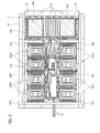
Fig. 2] Fig. 2 is a plan view ofFig. 1 , illustrating the vehicle with the floor panel removed. - [
Fig. 3] Fig. 3 is an enlarged view of the battery pack illustrated inFig. 2 . - [
Fig. 4] Fig. 4 is a schematic perspective view of the battery pack according to the embodiment of the present invention. - [
Fig. 5] Fig. 5 is a schematic perspective view illustrating a second battery module according to the embodiment of the present invention. - Firstly, a battery pack illustrated in
Figs. 1 to 3 will be described. InFigs. 1 and2 , reference numeral 1 denotes a vehicle body; 2, a vehicle interior; 3, a motor room in which an electric motor for traveling is mounted; 4, left and right front wheels; 5, left and right rear wheels; 6, front seats; 7, rear seats; and 11, a battery pack. - The
battery pack 11 is configured as a unit formed of first battery modules 13FL, 13FR arranged on the front side in a vehicle longitudinal direction, second battery modules 13CL, 13CR arranged on the center side in the vehicle longitudinal direction, and athird battery module 13R arranged on the rear side in the vehicle longitudinal direction. The battery modules 13FL, 13FR, 13CL, 13CR, 13R are arranged under a floor panel in their positions housed in abattery pack case 14 illustrated inFig. 3 . - More specifically, as illustrated in
Figs. 1 and2 , thebattery pack 11 is formed of the first battery modules 13FL, 13FR arranged below the left and right front seats 6, thethird battery module 13R arranged below the left and right rear seats 7, and the second battery modules 13CL, 13CR arranged directly under the floor panel between the left and right front seats 6 and the left and right rear seats 7. - As illustrated in
Figs. 1 to 3 , the front left first battery module 13FL is formed of a longitudinal side-by-side arrangement of two battery modules each formed of a vertical stacking of fourbattery shells 12 in a horizontal position. Likewise, the front right first battery module 13FR is formed of a longitudinal side-by-side arrangement of two battery modules each formed of a vertical stacking of fourbattery shells 12 in a horizontal position. - As illustrated in
Figs. 1 to 3 , the rearthird battery module 13R is formed ofmany battery shells 12 stacked in a vertical position along a vehicle width direction in such a way as to have substantially the same length as the overall length of the rear seats 7. - As illustrated in
Figs. 1 to 3 , the central left second battery module 13CL is formed of a longitudinal side-by-side arrangement of two battery modules each formed of a vertical stacking of twobattery shells 12 in a horizontal position. Likewise, the central right second battery module 13CR is formed of a longitudinal side-by-side arrangement of two battery modules each formed of a vertical stacking of twobattery shells 12 in a horizontal position. - As illustrated in
Fig. 3 , the first battery modules 13FL, 13FR are arranged in an orientation such thatelectrode terminals 12a of thebattery shells 12 which form the left first battery module 13FL mutually face theelectrode terminals 12a of thebattery shells 12 which form the right first battery module 13FR (or in such a manner that both are oriented toward the center in the vehicle width direction). - Also, as illustrated in
Fig. 3 , the rearthird battery module 13R is arranged in such a manner that allelectrode terminals 12a of thebattery shells 12 face toward the vehicle front. - Further, as illustrated in
Fig. 3 , the central left and right second battery modules 13CL, 13CR are arranged in an orientation such that theelectrode terminals 12a of thebattery shells 12 which form the left second battery module 13CL mutually face theelectrode terminals 12a of thebattery shells 12 which form the right second battery module 13CR (or in such a manner that both are oriented toward the center in the vehicle width direction). - Then, as illustrated in
Figs. 2 and3 , theelectrode terminals 12a of thebattery shells 12 which form the battery modules 13FL, 13FR, 13CL, 13CR, 13R are connected via a power supply cable to amotor power feeder 15 from the electric motor (or an inverter) in themotor room 3. The power supply cable is routed in a central space in the vehicle width direction between the front left and right first battery modules 13FL, 13FR, and in a central space in the vehicle width direction between the central left and right second battery modules 13CL, 13CR. -
Fig. 4 is a schematic perspective view of the battery shells. A configuration is such that the following relationship is established: h3 > h1 > h2, where h1 denotes the height of the first battery modules 13FL, 13FR (hereinafter, sometimes described as the first battery modules 13F) when mounted on the vehicle; h2, the height of the second battery modules 13CL, 13CR (hereinafter, sometimes described as the second battery modules 13C) when mounted on the vehicle; and h3, the height of thethird battery module 13R when mounted on the vehicle. - The first battery modules 13F are located below the left and right front seats 6, and the
third battery module 13R is located below the left and right rear seats 7. Therefore, the above-mentioned heights h1, h3 are set greater than the height h2 thereby to enable effective utilization of a space below the seats in thevehicle interior 2 as a mounting space for thebattery shells 12 and hence mounting of many batteries without impairing the comfort of thevehicle interior 2. Also, the height h3 is greater than the height h1, and thus, in thevehicle interior 2, the seat surfaces of the rear seats 32R are higher than the seat surfaces of the front seats 32F. This setting enables ensuring good visibility of passengers on the left and right rear seats 7. - In the embodiment, here, the total number of the
battery shells 12 of the first battery modules 13F and the second battery modules 13C is the same as the total number of thebattery shells 12 of thethird battery module 13R. Meanwhile, in a plan view of the vehicle, an area occupied by thethird battery module 13R is smaller than an area occupied by the first battery modules 13F and the second battery modules 13C. - Thus, the center of gravity of the
battery pack 11 is located on a relatively rear side of the vehicle in the vehicle longitudinal direction. The electric motor for traveling or the like is arranged in the vehicle front, and thus, the center of gravity of thebattery pack 11 is arranged on a relatively rear side of the vehicle and thereby the weight distribution of the vehicle taken as a whole can be brought close to the center position in the longitudinal direction. This enables ensuring stability of vehicle behavior. - Description will now be given with regard to a configuration of the
battery shell 12.Fig. 5 is a schematic view representing the second battery module. Thebattery shell 12 is formed substantially in the shape of a rectangular parallelepiped and has a long side p1, a short side p2, and a height side p3, the lengths of which are configured such that the following relationship is established: p1 > p2 > p3. Thebattery shell 12 has aflat surface 121 surrounded by the long side p1 and the short side p2, along side surface 122 surrounded by the long side p1 and the height side p3, and ashort side surface 123 surrounded by the short side p2 and the height side p3. Then, theelectrode terminals 12a are provided on theshort side surface 123. - The first battery module 13F and the second battery module 13C are arranged with the short side p2 of the
battery shell 12 along the vehicle longitudinal direction. The first battery module 13F and the second battery module 13C are modules arranged in a region where restrictions on their height direction are relatively stricter than restrictions on their width direction. Therefore, even if the battery modules are arranged with the long side p1 along the vehicle width direction, a space between the left and right battery modules can be ensured to thus facilitate wiring or the like. Also, the packing density of thebattery shells 12 can be increased by arranging the battery modules with the short side p2 along the vehicle longitudinal direction. Also, the height of the battery modules can be adjusted in fine increments by arranging the battery modules with the height side p3 of the shortest length along a vehicle vertical direction. - In other words, there are various limitations on the vehicle vertical direction, depending on the vehicle; however, in a case where the
battery shells 12 have their own common configuration, the height can be adjusted by how thebattery shells 12 are stacked one on top of another. Therefore, thebattery shells 12 can be efficiently mounted by setting the unit of adjustment in fine increments. - The
third battery module 13R is arranged with the height side p3 of thebattery shell 12 along the vehicle width direction. Thereby, the number of thebattery shells 12 stacked can be adjusted in fine increments, and thus,many battery shells 12 can be arranged by effective utilization of a space below the left and right rear seats 7. - Next, description will be given below with reference to
Figs. 2 and3 with regard to thin heater modules (or heater modules) for heating the battery modules for anti-freezing or other purposes under unused conditions. Incidentally, inFigs. 2 and3 , the thin heater modules are represented by hatching for the sake of convenience for clarity. The thin heater module is what is called a PTC heater, which increases its temperature to a predetermined temperature by the passage of electric current therethrough and then changes in resistance value so as to maintain the temperature. A configuration is such that a combination of the PTC heater and a uniform heat plate for uniformly distributing heat enables uniform heating of a set area range. Incidentally, a method in which a nichrome wire is arranged in a meandering fashion, a method in which hot water is circulated along a predetermined flow path, or the like, for example, may be applied to the heater, and the heater in itself is not particularly limited. - As represented by the diagonally shaded area in
Fig. 5 ,thin heater modules battery shells 12. In other words, efficient heating of the overall battery module requires uniform heat transfer to the stackedbattery shells 12. If the thin heater module is provided on theflat surface 121, only thebattery shell 12 stacked at an upper end or a lower end in close proximity to the thin heater module is heated, and thebattery shells 12 stacked in a central portion in the vertical direction are insufficiently heated, which in turn renders it difficult to achieve stabilization of performance. - Also, in a case where the thin heater module is provided on the short side surfaces 123, all
battery shells 12 can be heated; however, there arises the problem of low heating efficiency because of a small area facing the thin heater module. - In the embodiment, therefore, the
thin heater modules battery shells 12. - As previously mentioned, the front left and right first battery modules 13FL, 13FR are each formed of a four-layer stacking of the
battery shells 12 and have a large heat capacity. On the other hand, as previously mentioned, the central left and right second battery modules 13CL, 13CR are each formed of a two-layer stacking of thebattery shells 12 and have a small heat capacity and are thus prone to decrease in temperature. - In the embodiment, therefore, as illustrated in
Figs. 2 and3 , the front left and right first battery modules 13FL, 13FR are provided withthin heater modules thin heater modules thin heater modules thin heater modules - Incidentally, air warmed by the thin heater modules 22, which heat the second battery modules 13C, moves upward as indicated by arrows of
Fig. 4 . The warm air can also heat the first battery modules 13F. Likewise, air warmed by the thin heater modules 23, which heat the second battery modules 13C, moves upward. The warm air can also heat thethird battery module 13R. In other words, the second battery modules 13C are located at a position lower than the other battery modules, and thus, the relative positions of these are utilized to heat also the other battery modules. - The rear
third battery module 13R is different in stacking direction from the first battery module 13F and the second battery module 13C. Here, thelong side surface 122 is located toward an upper surface of the vehicle, and thus, thin battery heaters 24 are also arranged on the upper surface side of the vehicle. In this case, thethird battery module 13R has a larger number of thebattery shells 12 stacked than the front left and right first battery modules 13FL, 13FR and has the largest heat capacity and thus is less likely to decrease in temperature. However, the side surface side in the vehicle width direction is relatively susceptible to traveling wind or the like, and thethird battery module 13R is least likely to be cooled near the center in the vehicle width direction. Thus, the rearthird battery module 13R is provided with thethin heater modules third battery module 13R in both end regions thereof in the stacking direction of thebattery shells 12. - More specifically, when three regions divided in the stacking direction are set, the
thin heater modules third battery module 13R can be efficiently heated throughout its entire area. Also, the cost reduction can be achieved by narrowing the installation region for the thin heater modules. - The
thin heater modules module mounting surface 14a of thebattery pack case 14. - The
thin heater modules module mounting surface 14a of thebattery pack case 14. Thethin heater modules module mounting surface 14a of thebattery pack case 14. - The
thin heater modules rear battery module 13R at both ends thereof in the stacking direction of the battery shells, and are mounted on the batterymodule mounting surface 14a of thebattery pack case 14. - Incidentally, as previously mentioned, the battery power supply cable is routed in the central space in the vehicle width direction between the front left and right battery modules 13FL, 13FR, and in the central space in the vehicle width direction between the central left and right battery modules 13CL, 13CR. It is therefore desirable that electrode terminals of the
thin heater modules - Therefore, the electrode terminals of the
thin heater modules thin heater modules thin heater modules thin heater modules - Therefore, the
thin heater modules thin heater modules Figs. 2 and3 . - Here, the electrode terminals of the
thin heater modules thin heater modules - Also, the electrode terminals of the
thin heater modules thin heater modules - Advantageous effects of the embodiment will be described below.
- (1) The battery module includes the battery module 13 including the
plural battery shells 12 stacked one on top of another and each having the shape of a rectangular parallelepiped having three sides, and the thin heater modules 21, 22, 23, 24 each arranged in such a way as to face a side surface including a side along the stacking direction, of the battery module 13, and each configured to heat the battery module 13. - Specifically, the thin heater modules 21, 22, 23, 24 are each provided in such a way as to face the side surface including the side along the stacking direction. Thereby, all
battery shells 12 are uniformly heated, and also, heating takes place inside thebattery pack case 14 to thus enable achieving an improvement in heating efficiency. - (2) The
battery shells 12 each have the shape of a rectangular parallelepiped having the long side p1, the short side p2, and the height side p3 shorter than the long side p1 and the short side p2, and the stacking direction is a direction along the height side p3, and the thin heater modules 21, 22, 23, 24 are each arranged in such a way as to face thelong side surface 122 as a side surface including the long side p1. - Specifically, the
battery shells 12 are stacked in the direction along the shortest height side p3, and thereby, length adjustment of the battery module 13 in the direction along the height side p3 can be set in fine increments to thus enable efficient mounting on the vehicle. Also, the thin heater modules are each arranged in such a way as to face thelong side surface 122 thereby to enable achieving the improvement in the heating efficiency, as well as uniform heating of allbattery shells 12. - (3) The battery module 13 includes the first battery module 13F located below the front seat and having the first height h1, the second battery module 13C located below the floor panel at the foot of the rear seat between the front seat and the rear seat and having the second height h2, and the
third battery module 13R located below the rear seat and having the third height h3, which are arranged below the floor panel of the vehicle in order from the vehicle front, and the second height h2 is less than the first and third heights h1, h3. - This enables effective utilization of the space below the seats in the
vehicle interior 2 as the mounting space for thebattery shells 12 and hence mounting of many batteries without impairing the comfort of thevehicle interior 2. - (4) The thin heater module 21 is arranged in front of the first battery module 13F in the vehicle longitudinal direction.
- Specifically, the first battery module 13F arranged in the vehicle front is susceptible to traveling wind or the like and is prone to cooling. Thus, installation in a cooling-prone location alone enables achieving cost reduction as well as ensuring heating performance. Incidentally, the first battery module 13F has a larger volumetric capacity and hence also a larger heat capacity, as compared to the second battery module 13C. Therefore, the vehicle rear side is relatively less likely to be cooled, and thus, sufficient heating performance can be achieved even if the thin heater module 21 is installed only in the vehicle front. Incidentally, the first battery module 13F is installed below the front seat, and thus, its height direction is difficult to ensure. Therefore, the
battery shells 12 are stacked along the vehicle vertical direction and thelong side surface 122 is arranged along the vehicle width direction, and thereby, thebattery shells 12 can be efficiently arranged. - (5) The thin heater modules 22, 23 are arranged in front of and behind the second battery module 13C in the vehicle longitudinal direction.
- Specifically, the second battery module 13C, although located in a central portion of the
battery pack 11, has a smaller volumetric capacity and hence also a smaller heat capacity and is more prone to cooling, as compared to the other battery modules. Therefore, the thin heater modules 21 are arranged in both the front and rear sides in the vehicle longitudinal direction thereby to enable ensuring the heating performance. Incidentally, the second battery module 13F is installed below the floor panel at the foot of the rear seat arranged between the front seat and the rear seat, and thus, its height direction is difficult to ensure. Therefore, thebattery shells 12 are stacked along the vehicle vertical direction and thelong side surface 122 is arranged along the vehicle width direction, and thereby, thebattery shells 12 can be efficiently arranged. - (6) The thin heater module 24 is arranged above the
third battery module 13R in the vehicle vertical direction. - Specifically, the third battery module 13C is installed below the rear seat, and thus, restrictions on its height direction are relatively less strict. Therefore, the
battery shells 12 are stacked in the vehicle width direction and the thin heater module 24 is installed above the stackedbattery shells 12, and thereby, a sufficient space can be ensured in the vehicle width direction to thus enable efficient arrangement of thebattery shells 12. - (7) The thin heater modules 24 are arranged in both end regions of the
third battery module 13R in the vehicle width direction. - Specifically, the third battery module 13C has a larger volumetric capacity and hence also a larger heat capacity, as compared to the second battery module 13C. The center in the vehicle width direction, in particular, is unsusceptible to the outside air and does not tend to be cooled. Therefore, the thin heater modules 24 are installed in both end regions in the vehicle width direction, or equivalently, are not installed in the center region in the vehicle width direction, thereby to enable achieving sufficient heating performance as well as cost reduction.
- Incidentally, the entire contents of Japanese Patent Application No.
2011-054086 (filed on March 11, 2011 - Also, while the contents of the present invention have been described with reference to the form of the embodiment, it is to be understood that the present invention is not limited to the description, and it would be obvious to those skilled in the art that various modifications and improvements could be made thereto.
- According to the battery module according to the present invention, all battery shells are uniformly heated, and also, the battery shells are directly heated to thus enable achieving an improvement in heating efficiency.
-
- 1
- vehicle body
- 2
- vehicle interior
- 3
- motor room
- 4
- left and right front wheels
- 5
- left and right rear wheels
- 6
- front seat
- 7
- rear seat
- 11
- battery pack
- 12
- battery shell
- 12a
- electrode terminal
- 13FL
- front left battery module (battery module)
- 13FR
- front right battery module (battery module)
- 13CL
- central left battery module (battery module)
- 13CR
- central right battery module (battery module)
- 13R
- rear battery module (battery module)
- 14
- battery pack case
- 14a
- battery module mounting surface
- 15
- motor power feeder
- 21L, 22R, 22L, 22R, 23L, 23R
- thin heater modules (heater modules)
Claims (7)
- A battery module comprising:a battery module including a plurality of battery shells each in the shape of a rectangular parallelepiped, stacked one on top of another; anda heater module arranged in such a way as to face a side surface including a side along a stacking direction, of the battery module, and configured to heat the battery module.
- The battery module according to claim 1, wherein
the battery shells each have the shape of a rectangular parallelepiped having a long side, a short side, and a height side shorter than the long side and the short side,
the stacking direction is a direction along the height side, and
the heater module is arranged in such a way as to face a side surface including the long side. - The battery module according to any one of claims 1 and 2, wherein
the battery module includes a first battery module located below a front seat and having a first height, a second battery module located below a floor panel at the foot of a rear seat between the front seat and the rear seat and having a second height, and a third battery module located below the rear seat and having a third height, which are arranged below the floor panel of a vehicle in order from the vehicle front, and
the second height is less than the first and third heights. - The battery module according to claim 3, wherein the heater module is arranged in front of the first battery module in a vehicle longitudinal direction.
- The battery module according to any one of claims 3 and 4, wherein the heater modules are arranged in front of and behind the second battery module in the vehicle longitudinal direction.
- The battery module according to any one of claims 3 to 5, wherein the heater module is arranged above the third battery module in a vehicle vertical direction.
- The battery module according to claim 6, wherein the heater modules are arranged in both end regions of the third battery module in a vehicle width direction.
Applications Claiming Priority (2)
| Application Number | Priority Date | Filing Date | Title |
|---|---|---|---|
| JP2011054086A JP2012190691A (en) | 2011-03-11 | 2011-03-11 | Battery module |
| PCT/JP2012/055124 WO2012124481A1 (en) | 2011-03-11 | 2012-02-29 | Battery module |
Publications (2)
| Publication Number | Publication Date |
|---|---|
| EP2685545A1 true EP2685545A1 (en) | 2014-01-15 |
| EP2685545A4 EP2685545A4 (en) | 2014-08-27 |
Family
ID=46830556
Family Applications (1)
| Application Number | Title | Priority Date | Filing Date |
|---|---|---|---|
| EP12757333.5A Withdrawn EP2685545A4 (en) | 2011-03-11 | 2012-02-29 | Battery module |
Country Status (8)
| Country | Link |
|---|---|
| US (1) | US20130344371A1 (en) |
| EP (1) | EP2685545A4 (en) |
| JP (1) | JP2012190691A (en) |
| KR (1) | KR20130133279A (en) |
| CN (1) | CN103430377A (en) |
| CA (1) | CA2829867A1 (en) |
| RU (1) | RU2539351C1 (en) |
| WO (1) | WO2012124481A1 (en) |
Families Citing this family (8)
| Publication number | Priority date | Publication date | Assignee | Title |
|---|---|---|---|---|
| WO2013084936A1 (en) * | 2011-12-09 | 2013-06-13 | 本田技研工業株式会社 | Vehicle-mounted battery pack structure |
| US20160056418A1 (en) * | 2014-08-21 | 2016-02-25 | Ford Global Technologies, Llc | Li-ion monoblock battery for stop/start applications |
| US20160093848A1 (en) | 2014-09-30 | 2016-03-31 | Johnson Controls Technology Company | Modular approach for advanced battery modules having different electrical characteristics |
| RU2625461C2 (en) * | 2015-01-27 | 2017-07-14 | Сергей Борисович Орлов | Current power supply |
| EP3633761B1 (en) * | 2017-05-30 | 2021-08-04 | Nissan Motor Co., Ltd. | Battery pack for mounting on vehicle |
| WO2019039116A1 (en) * | 2017-08-22 | 2019-02-28 | 日立オートモティブシステムズ株式会社 | Battery pack |
| JP7339065B2 (en) * | 2019-08-21 | 2023-09-05 | マツダ株式会社 | vehicle battery pack |
| DE102020209492A1 (en) * | 2020-07-28 | 2022-02-03 | Robert Bosch Gesellschaft mit beschränkter Haftung | Heated battery module |
Citations (3)
| Publication number | Priority date | Publication date | Assignee | Title |
|---|---|---|---|---|
| JP2008047371A (en) * | 2006-08-11 | 2008-02-28 | Toshiba Corp | Battery pack and charge and discharge method of battery pack |
| WO2011007537A1 (en) * | 2009-07-17 | 2011-01-20 | Nissan Motor Co., Ltd. | Battery pack |
| EP2685547A1 (en) * | 2011-03-11 | 2014-01-15 | Nissan Motor Co., Ltd | Vehicle battery |
Family Cites Families (15)
| Publication number | Priority date | Publication date | Assignee | Title |
|---|---|---|---|---|
| JP2702372B2 (en) * | 1993-03-26 | 1998-01-21 | 日本碍子株式会社 | Heating device for high temperature secondary battery |
| US6085854A (en) * | 1994-12-13 | 2000-07-11 | Nissan Motor Co., Ltd. | Battery frame structure for electric motorcar |
| RU2088001C1 (en) * | 1995-05-15 | 1997-08-20 | Военный автомобильный институт | Storage battery with inner heating |
| JP3733629B2 (en) * | 1995-12-08 | 2006-01-11 | 日産自動車株式会社 | Secondary battery temperature control device |
| JP3767004B2 (en) * | 1996-03-11 | 2006-04-19 | マツダ株式会社 | Engine secondary air supply device |
| US5948298A (en) * | 1996-04-26 | 1999-09-07 | Ford Global Technologies, Inc. | Battery heating system |
| JPH11213962A (en) * | 1998-01-30 | 1999-08-06 | Yuasa Corp | Storage battery |
| DE10260551A1 (en) * | 2002-12-21 | 2004-07-01 | Otto Hans Happe | Battery for a motor vehicle with heater elements in an acid-proof jacket starts up an internal combustion engine to drive a motor vehicle |
| US7556885B2 (en) * | 2003-11-14 | 2009-07-07 | Sony Corporation | Battery pack |
| US7531270B2 (en) * | 2006-10-13 | 2009-05-12 | Enerdel, Inc. | Battery pack with integral cooling and bussing devices |
| JP4948187B2 (en) | 2007-01-26 | 2012-06-06 | プライムアースEvエナジー株式会社 | Laminated thin heater, laminated thin heater with lead wire, battery structure with heater, and heater unit |
| JP5326503B2 (en) * | 2008-11-05 | 2013-10-30 | 株式会社デンソー | Battery cooling device |
| JP5185876B2 (en) * | 2009-03-31 | 2013-04-17 | 本田技研工業株式会社 | Battery assembly |
| JP5640382B2 (en) * | 2009-05-26 | 2014-12-17 | 日産自動車株式会社 | Vehicle battery assembly cooling structure and battery assembly with water jacket |
| JP2011014436A (en) * | 2009-07-03 | 2011-01-20 | Panasonic Corp | Battery heating device |
-
2011
- 2011-03-11 JP JP2011054086A patent/JP2012190691A/en active Pending
-
2012
- 2012-02-29 CN CN2012800129223A patent/CN103430377A/en active Pending
- 2012-02-29 US US14/004,067 patent/US20130344371A1/en not_active Abandoned
- 2012-02-29 RU RU2013145549/07A patent/RU2539351C1/en not_active IP Right Cessation
- 2012-02-29 EP EP12757333.5A patent/EP2685545A4/en not_active Withdrawn
- 2012-02-29 KR KR1020137026229A patent/KR20130133279A/en not_active Application Discontinuation
- 2012-02-29 WO PCT/JP2012/055124 patent/WO2012124481A1/en active Application Filing
- 2012-02-29 CA CA2829867A patent/CA2829867A1/en not_active Abandoned
Patent Citations (3)
| Publication number | Priority date | Publication date | Assignee | Title |
|---|---|---|---|---|
| JP2008047371A (en) * | 2006-08-11 | 2008-02-28 | Toshiba Corp | Battery pack and charge and discharge method of battery pack |
| WO2011007537A1 (en) * | 2009-07-17 | 2011-01-20 | Nissan Motor Co., Ltd. | Battery pack |
| EP2685547A1 (en) * | 2011-03-11 | 2014-01-15 | Nissan Motor Co., Ltd | Vehicle battery |
Non-Patent Citations (1)
| Title |
|---|
| See also references of WO2012124481A1 * |
Also Published As
| Publication number | Publication date |
|---|---|
| KR20130133279A (en) | 2013-12-06 |
| WO2012124481A1 (en) | 2012-09-20 |
| CA2829867A1 (en) | 2012-09-20 |
| RU2539351C1 (en) | 2015-01-20 |
| US20130344371A1 (en) | 2013-12-26 |
| JP2012190691A (en) | 2012-10-04 |
| CN103430377A (en) | 2013-12-04 |
| EP2685545A4 (en) | 2014-08-27 |
Similar Documents
| Publication | Publication Date | Title |
|---|---|---|
| EP2685545A1 (en) | Battery module | |
| CA2810826C (en) | In-vehicle battery | |
| EP2685548A1 (en) | Vehicle battery | |
| CN105470604B (en) | Vehicle battery | |
| JP6099194B2 (en) | Storage device cooling structure | |
| EP2685782B1 (en) | Heater module | |
| US20150244039A1 (en) | Traction battery thermal plate with transverse channel configuration | |
| JP6766174B2 (en) | Electrical connection device, heating device, and ventilation, heating and / or air conditioning unit | |
| JP7112974B2 (en) | Automotive battery temperature controller | |
| JP5790041B2 (en) | Thin heater module |
Legal Events
| Date | Code | Title | Description |
|---|---|---|---|
| PUAI | Public reference made under article 153(3) epc to a published international application that has entered the european phase |
Free format text: ORIGINAL CODE: 0009012 |
|
| 17P | Request for examination filed |
Effective date: 20131001 |
|
| AK | Designated contracting states |
Kind code of ref document: A1 Designated state(s): AL AT BE BG CH CY CZ DE DK EE ES FI FR GB GR HR HU IE IS IT LI LT LU LV MC MK MT NL NO PL PT RO RS SE SI SK SM TR |
|
| DAX | Request for extension of the european patent (deleted) | ||
| A4 | Supplementary search report drawn up and despatched |
Effective date: 20140728 |
|
| RIC1 | Information provided on ipc code assigned before grant |
Ipc: H01M 10/60 20140101ALI20140722BHEP Ipc: B60L 11/18 20060101ALI20140722BHEP Ipc: B60L 1/02 20060101ALI20140722BHEP Ipc: H01M 10/647 20140101ALI20140722BHEP Ipc: H01M 2/10 20060101ALI20140722BHEP Ipc: H01M 10/625 20140101ALI20140722BHEP Ipc: H01M 10/615 20140101ALI20140722BHEP Ipc: B60K 1/04 20060101AFI20140722BHEP |
|
| 17Q | First examination report despatched |
Effective date: 20170530 |
|
| STAA | Information on the status of an ep patent application or granted ep patent |
Free format text: STATUS: THE APPLICATION HAS BEEN WITHDRAWN |
|
| 18W | Application withdrawn |
Effective date: 20170704 |