EP2685465A1 - Flat cable and wire harness - Google Patents
Flat cable and wire harness Download PDFInfo
- Publication number
- EP2685465A1 EP2685465A1 EP11860445.3A EP11860445A EP2685465A1 EP 2685465 A1 EP2685465 A1 EP 2685465A1 EP 11860445 A EP11860445 A EP 11860445A EP 2685465 A1 EP2685465 A1 EP 2685465A1
- Authority
- EP
- European Patent Office
- Prior art keywords
- electric wires
- flat cable
- weft
- wiring harness
- electric
- Prior art date
- Legal status (The legal status is an assumption and is not a legal conclusion. Google has not performed a legal analysis and makes no representation as to the accuracy of the status listed.)
- Withdrawn
Links
- 230000000630 rising effect Effects 0.000 claims abstract description 8
- 239000000463 material Substances 0.000 description 8
- 239000004020 conductor Substances 0.000 description 6
- 230000001012 protector Effects 0.000 description 6
- 230000013011 mating Effects 0.000 description 4
- 239000002184 metal Substances 0.000 description 4
- 229910052751 metal Inorganic materials 0.000 description 4
- 238000005452 bending Methods 0.000 description 3
- 238000009941 weaving Methods 0.000 description 3
- OKTJSMMVPCPJKN-UHFFFAOYSA-N Carbon Chemical compound [C] OKTJSMMVPCPJKN-UHFFFAOYSA-N 0.000 description 2
- 229920000742 Cotton Polymers 0.000 description 2
- 239000004743 Polypropylene Substances 0.000 description 2
- 238000013459 approach Methods 0.000 description 2
- 229910052799 carbon Inorganic materials 0.000 description 2
- 239000004744 fabric Substances 0.000 description 2
- 239000012212 insulator Substances 0.000 description 2
- 229920006122 polyamide resin Polymers 0.000 description 2
- 229920000728 polyester Polymers 0.000 description 2
- -1 polypropylene Polymers 0.000 description 2
- 229920001155 polypropylene Polymers 0.000 description 2
- 229920003002 synthetic resin Polymers 0.000 description 2
- 239000000057 synthetic resin Substances 0.000 description 2
- RYGMFSIKBFXOCR-UHFFFAOYSA-N Copper Chemical compound [Cu] RYGMFSIKBFXOCR-UHFFFAOYSA-N 0.000 description 1
- 229910052802 copper Inorganic materials 0.000 description 1
- 239000010949 copper Substances 0.000 description 1
- 230000000694 effects Effects 0.000 description 1
- 238000012986 modification Methods 0.000 description 1
- 230000004048 modification Effects 0.000 description 1
- 229920005672 polyolefin resin Polymers 0.000 description 1
- 229920000915 polyvinyl chloride Polymers 0.000 description 1
- 239000004800 polyvinyl chloride Substances 0.000 description 1
Images


Classifications
-
- H—ELECTRICITY
- H01—ELECTRIC ELEMENTS
- H01B—CABLES; CONDUCTORS; INSULATORS; SELECTION OF MATERIALS FOR THEIR CONDUCTIVE, INSULATING OR DIELECTRIC PROPERTIES
- H01B7/00—Insulated conductors or cables characterised by their form
- H01B7/08—Flat or ribbon cables
-
- H—ELECTRICITY
- H01—ELECTRIC ELEMENTS
- H01B—CABLES; CONDUCTORS; INSULATORS; SELECTION OF MATERIALS FOR THEIR CONDUCTIVE, INSULATING OR DIELECTRIC PROPERTIES
- H01B7/00—Insulated conductors or cables characterised by their form
- H01B7/08—Flat or ribbon cables
- H01B7/083—Parallel wires, incorporated in a fabric
-
- H—ELECTRICITY
- H01—ELECTRIC ELEMENTS
- H01B—CABLES; CONDUCTORS; INSULATORS; SELECTION OF MATERIALS FOR THEIR CONDUCTIVE, INSULATING OR DIELECTRIC PROPERTIES
- H01B13/00—Apparatus or processes specially adapted for manufacturing conductors or cables
- H01B13/012—Apparatus or processes specially adapted for manufacturing conductors or cables for manufacturing wire harnesses
- H01B13/01263—Tying, wrapping, binding, lacing, strapping or sheathing harnesses
-
- H—ELECTRICITY
- H02—GENERATION; CONVERSION OR DISTRIBUTION OF ELECTRIC POWER
- H02G—INSTALLATION OF ELECTRIC CABLES OR LINES, OR OF COMBINED OPTICAL AND ELECTRIC CABLES OR LINES
- H02G3/00—Installations of electric cables or lines or protective tubing therefor in or on buildings, equivalent structures or vehicles
- H02G3/02—Details
- H02G3/04—Protective tubing or conduits, e.g. cable ladders or cable troughs
- H02G3/0462—Tubings, i.e. having a closed section
- H02G3/0487—Tubings, i.e. having a closed section with a non-circular cross-section
Definitions
- the present invention relates to a flat cable having a plurality of electric wires arranged in various electric machines, and a wiring harness provided with the flat cable.
- this wiring harness is arranged for electrically connecting various electronic devices to each other.
- this wiring harness includes: a flat cable formed in a flat shape by integrating covering sections made of insulator with a connecting section made of insulator, each of the covering section covering each of conductors having the same diameter and arranged parallel to each other at regular intervals; a connector attached to ends of the conductors of this flat cable; and a corrugate tube, a protector, and the like for receiving and protecting the flat cable.
- the above wiring harness is arranged in the above electric machine when the connector is fitted to a connector provided on various electronic devices.
- the wiring harness supplies necessary signals and the like to the various electronic devices of the above electric machine.
- the above conventional wiring harness is provided with a corrugate tube, a protector, and the like for receiving and protecting the flat cable.
- the conventional wiring harness is provided with the corrugate tube and the protector independent from the flat cable, the number of components is increased, and the wiring harness becomes large-sized for receiving the flat cable in the corrugate tube and the protector.
- an object of the present invention is to provide a flat cable able to decrease the number of components and able to be small-sized, and to provide a wiring harness provided with the flat cable.
- a flat cable including:
- the flat cable as described in the first aspect wherein outer diameters of at least two electric wires among the plurality of electric wires are different from each other.
- the flat cable as described in the first or second aspect further including a warp disposed parallel to the plurality of electric wires in between the plurality of electric wires.
- a wiring harness including:
- the flat cable of the present invention described in the first aspect, because the flat cable is provided with the weft woven with the electric wires so as to prevent the weft from moving relative to the electric wires, the weft covers a periphery of the plurality of electric wires.
- the flat cable is formed by weaving a plurality of electric wires and an elongated weft interlaced in a certain rule, an outer diameter and the number of the electric wires woven with the weft can be easily changed.
- the warp is provided in between the plurality of electric wires, tensile stress and bending stress acting on the flat cable can be born by the warp.
- the weft covers the periphery of the plurality of electric wires at the end of the flat cable.
- the weft covers the periphery of the plurality of electric wires, the weft protects the electric wires. Therefore, the plurality of electric wires, namely, the flat cable can be protected without using the corrugate tube or the protector independent from the flat cable. Therefore, the number of components of the wiring harness can be reduced. Further, because the weft is tightly woven with the electric wires so as to prevent the weft from moving, the weft tightly contacts the electric wires. Therefore, the flat cable, namely, the wiring harness provided with the flat cable can be small-sized.
- the flat cable is formed by weaving a plurality of electric wires and an elongated weft interlaced in a certain rule, an outer diameter and the number of the electric wires woven with the weft can be easily changed. Therefore, the conductors having various shapes can be integrated without increasing the production cost.
- the conductors having various shapes can be surely integrated without increasing the production cost.
- the mechanical strength of the flat cable can be improved.
- the wiring harness is provided with the above flat cable, the number of components of the wiring harness can be reduced, and the wiring harness can be small-sized.
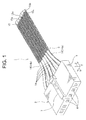
- a wiring harness and a flat cable according to an embodiment of the present invention will be explained with reference to Figs. 1 to 4 .
- a wiring harness 1 is arranged in a vehicle as an electric machine, and electrically connects various electronic devices mounted on the vehicle to each other. As shown in Figs. 1 and 2 , the wiring harness 1 includes a connector 2 and a flat cable 3.
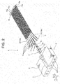
- the connector 2 includes: a connector housing 4; and a plurality of female terminals 5 (hereinafter only referred to as female terminal and Fig. 2 shows only one terminal and others are omitted).
- a longitudinal direction of a later-described electric wire 14 and a terminal receiving chamber 6 is referred to as a depth direction, and denoted by an arrow Y.
- a direction perpendicular to the depth direction Y and an arranging direction of a later-described plurality of terminal receiving chambers 6 is referred to as a width direction, and denoted by an arrow X.
- a direction perpendicular to both the depth direction Y and the width direction X is referred to as a thickness direction, and denoted by an arrow Z.
- the connector housing 4 is made of insulating synthetic resin, and formed in a tubular (boxy) shape.
- a plurality of terminal receiving chambers 6 is provided at an inside of the connector housing 4, and a locking arm 7 is provided on an outer surface of the connector housing 4.
- the terminal receiving chamber 6 is a straight space (hole).
- a longitudinal direction of the terminal receiving chamber 6 is parallel to the depth direction Y.
- the plurality of terminal receiving chambers 6 is arranged parallel to each other. Both ends of the terminal receiving chamber 6 are opened on the outer surface of the connector housing 4.
- the locking arm 7 is fitted to a connector housing of a mating connector.
- the female terminal 5 After an electric wire 14 is attached to a later-described wire connecting portion 8 of the female terminal 5, the female terminal 5 is received in the terminal receiving chamber 6. Then, the female terminal 5 is electrically connected to a core wire 17 of the electric wire 14, namely, to the electric wire 14.
- the female terminal 5 is made of conductive plate metal, and integrally includes: a wire connecting portion 8; and an electric contact portion 9.
- the wire connecting portion 8 integrally includes: a flat-plate-shaped bottom plate 10; a pair of core wire 17 caulking pieces 11; and a pair of cover caulking pieces 12.
- the bottom plate 10 is formed in a rectangular shape in plan view.
- the pair of core wire 17 caulking pieces 11 is provided at the center in a longitudinal direction of the bottom plate 10.
- the pair of core wire 17 caulking pieces 11 stands up from both edges in a width direction of the bottom plate 10.
- the pair of core 17 wire caulking pieces 11 is bent so that an edge away from the bottom plate 10 approaches the bottom plate 10, and holds the core wire 17 with the bottom plate 10 to caulk the core wire 17.
- the pair of cover caulking pieces 12 is provided at one end in a longitudinal direction of the bottom plate 10.
- the pair of cover caulking pieces 12 stands up from both edges in a width direction of the bottom plate 10.
- the pair of cover caulking pieces 12 is bent so that an edge away from the bottom plate 10 approaches the bottom plate 10, and holds the cover 18, namely, the electric wire 14 with the bottom plate 10 to caulk the electric wire 14.
- the wire connecting portion 8 When the pair of core wire 17 caulking pieces 11 caulks the core wire 17, and the pair of cover caulking pieces 12 caulks the cover 18, the wire connecting portion 8 is electrically and mechanically connected to the electric wire 14.
- a longitudinal direction of the wire connecting portion 8 and a longitudinal direction of the electric wire 14 connected to the wire connecting portion 8 are parallel to each other.
- the electric contact portion 9 integrally includes: a tubular shaped portion 13; and a not-shown spring piece provided in the tubular shaped portion 13.
- the tubular shaped portion 13 is continued to the bottom plate 10 of the wire connecting portion 8.
- the spring piece holds a tab of a mating male terminal (hereinafter referred to as male terminal) inserted into the tubular shaped portion 13 with an inner surface of the tubular shaped portion 13 to electrically connect the male and female terminals.
- male terminal a mating male terminal
- the above connector 2 is assembled. Then, the connector 2 is fitted to a mating connector. Incidentally, in the embodiment shown in Fig. 2 , only the connector 2 attached to one end of the flat cable 3 is shown. However, according to the present invention, the connector 2 is properly attached to a necessary position such as the other end of the flat cable 3.
- the flat cable 3 includes: a plurality of electric wires 14 arranged parallel to each other with a gap; and an elongated weft 15. Namely, the electric wires 14 adjacent to each other among the plurality of electric wires 14 are disposed with a gap therebetween.
- the electric wire 14 includes: a conductive core wire 17; and an insulating cover 18.
- the core wire 17 is defined by bundling a plurality of element wires.
- the element wire is made of metal such as copper.
- the cover 18 is made of insulating synthetic resin such as polyvinyl chloride or polyolefin resin, and covers the core wire 17.
- outer diameters of the plurality of electric wires 14 are the same.
- the weft 15 is formed in a deformable long filament.
- the material of the weft 15 one or more materials can be properly selected and used from among the materials used for defining a conventional woven (fabric) such as polyester, polyamide resin, polypropylene, cotton, carbon, metal, or the like.
- a second parallel section 15d (corresponding to the parallel section) overlapped with the electric wire 14a is formed and caught by the crossing section 15a.
- a third parallel portion (corresponding to the parallel section) again overlapped with the electric wire 14a is formed.
- the crossing section alternately rising and falling from the electric wire 14a and crossing to the electric wires 14 is formed.
- the weft 15 is crossed with respect to the plurality of electric wires 14, 14a, 14b by a certain rule to be woven, by forming sequentially and repeatedly the crossing section 15a, the parallel section 15b, the second crossing section 15c, the second parallel section 15d, the third parallel section 15e, and the crossing section 15a, and by catching the second parallel section 15d together with the crossing section 15a by the second crossing section 15c.
- the crossing sections 15a, 15b are arranged rising and falling by a certain rule. Further, the crossing sections 15a, 15c adjacent to each other are arranged with a gap therebetween. At each of the crossing sections 15a, 15c, the weft 15 is perpendicular to (crossing) the longitudinal direction of the electric wires 14, 14a, 14b.
- the weft 15 is woven with respect to only the plurality of electric wires 14, 14a, 14b in the above described manner, the plurality of electric wires 14, 14a, 14b are arranged in the same plane with a gap therebetween and parallel to each other, and fixed to each other.
- the weft 15 and the electric wires 14, 14a, 14b are tightly woven with each other so as to prevent the weft 15 from moving along the longitudinal direction of electric wires 14, 14a, 14b relative to the electric wires 14, 14a, 14b.
- the phrase "the weft 15 and the electric wires 14, 14a, 14b are tightly woven with each other" indicates that the weft 15 is prevented from moving along the longitudinal direction of electric wires 14, 14a, 14b relative to the electric wires 14, 14a, 14b.
- the above wiring harness 1 is assembled as follows. First, the above plurality of electric wires 14, 14a, 14b having a specific length is arranged parallel to each other, and the weft 15 is tightly woven with respect to the plurality of electric wires 14, 14a, 14b in a manner that the crossing section 15a, the parallel section 15b, the second crossing section 15c, the second parallel section 15d the third parallel section 15e, and the crossing section 15a are sequentially and repeatedly formed. In this way, as shown in Fig. 3 , the flat cable 3 is assembled. Then, the female terminals 5 are attached to ends of the electric wires 14, 14a, 14b of the flat cable 3, and inserted into the terminal receiving chambers 6 of the connector housing 4. Thereby, the above wiring harness 1 is assembled. The wiring harness 1 assembled in this way is arranged in a vehicle, and the connector 2 is fitted to a mating connector provided on electronic devices mounted on the vehicle.
- the flat cable 3 is provided with the weft 15 woven with respect to the plurality of electric wires 14, 14a, 14b so as to prevent the weft 15 from moving relative to the plurality of electric wires 14, 14a, 14b. Therefore, as shown in Fig. 4 , the weft 15 covers a periphery of the plurality of electric wires 14, 14a, 14b. Therefore, the plurality of electric wires 14, 14a, 14b, namely, the flat cable 3 can be protected without using the corrugate tube or the protector independent from the flat cable 3. Therefore, the number of components of the wiring harness 1 can be reduced.
- the weft 15 is tightly woven with the electric wires 14, 14a, 14b so as to prevent the weft 15 from moving, the weft 15 tightly contacts the electric wires 14, 14a, 14b. Therefore, the flat cable 3, namely, the wiring harness 1 provided with the flat cable 3 can be small-sized.
- the flat cable 3 is formed by weaving the plurality of electric wires 14, 14a, 14b and the elongated weft 15 interlaced in a certain rule, an outer diameter and the number of the electric wires 14, 14a, 14b woven with the weft 15 can be easily changed. Therefore, the conductors having various shapes can be integrated without increasing the production cost.
- the weft 15 is prevented from separating from the electric wires 14, 14a, 14b.
- the wiring harness 1 of this embodiment includes the above flat cable 3, the number of the components of the wiring harness 1 can be reduced, and the wiring harness 1 can be small-sized.
- the above flat cable 3 includes the plurality of electric wires 14, 14a, 14b having the same outer diameters.
- the electric wires 14, 14a, 14b defining the flat cable 3 the electric wires 14, 14a, 14b having the different outer diameters can be properly selected.
- an outer diameter of one electric wire 14b positioned at the topmost in Fig. 5 is larger than those of the other electric wires 14, 14a, and the outer diameters of the electric wires 14, 14a are the same.
- outer diameters of at least two electric wires are different from each other.
- the same components as the above embodiments are denoted by the same reference signs, and an explanation thereof is omitted.
- outer diameters of at least two among the plurality of electric wires 14, 14a, 14b are different from each other. Therefore, the electric wires 14, 14a, 14b having necessary diameters can be properly used. Therefore, the conductors having various shapes can be surely integrated without increasing the production cost.
- the weft 15 is woven with respect to only the plurality of electric wires 14, 14a, 14b.
- a warp 16 may be provided in between the plurality of electric wires 14, 14a, 14b.
- the configuration of the warp 16 may be completely the same as the weft 15 or may be different from the weft 15.
- the material of the warp 16 may be the same as the weft 15, and may be different from the weft 15.
- one or more materials can be properly selected and used from among the materials used for defining a conventional woven (fabric) such as polyester, polyamide resin, polypropylene, cotton, carbon, metal, or the like.
- a conventional woven (fabric) such as polyester, polyamide resin, polypropylene, cotton, carbon, metal, or the like.
- the crossing sections 15a, 15c alternately rises and falls with respect to the plurality of electric wires 14, 14a, 14b and the warp 16.
- the same components as the above embodiments are denoted by the same reference signs, and an explanation thereof is omitted.
- a plurality of warps 16 may be provided in between the electric wires 14, 14a, 14b adjacent to each other.
- the warp 16 made of the same material as the weft 15 is provided in between the plurality of electric wires 14, 14a, 14b. Therefore, the tensile stress and the bending stress acting on the flat cable 3 can be born by the warp 16. Therefore, the mechanical strength of the flat cable 3 can be improved.
- the wiring harness 1 arranged in a vehicle is provided.
- the wiring harness 1 can be used not only for a vehicle but also for an electronic device and an electric machine such as a portable computer or a mobile terminal.
- the weft 15 can be woven with respect to the plurality of electric wires 14, 14a, 14b by not only a weave shown in the above embodiment, but also the other weaves such as plane weave, twill weave, or satin weave. Further, even in a case of the weave shown in the above embodiment, at the crossing sections 15a, 15c, the weft 15 may be woven in a manner to rise and fall with respect to some of the plurality of electric wires 14, 14a, 14b and the warp 16 by a certain rule.
- the above embodiment only shows a representative example of the present invention.
- the present invention is not limited to the embodiment. Namely, various modifications can be practiced within a scope of the present invention.
Landscapes
- Insulated Conductors (AREA)
Abstract
Description
- The present invention relates to a flat cable having a plurality of electric wires arranged in various electric machines, and a wiring harness provided with the flat cable.
- In an electric machine such as a vehicle as a moving object, a wiring harness is arranged for electrically connecting various electronic devices to each other. In some cases, this wiring harness includes: a flat cable formed in a flat shape by integrating covering sections made of insulator with a connecting section made of insulator, each of the covering section covering each of conductors having the same diameter and arranged parallel to each other at regular intervals; a connector attached to ends of the conductors of this flat cable; and a corrugate tube, a protector, and the like for receiving and protecting the flat cable.
- The above wiring harness is arranged in the above electric machine when the connector is fitted to a connector provided on various electronic devices. The wiring harness supplies necessary signals and the like to the various electronic devices of the above electric machine.
- The above conventional wiring harness is provided with a corrugate tube, a protector, and the like for receiving and protecting the flat cable. In this way, because the conventional wiring harness is provided with the corrugate tube and the protector independent from the flat cable, the number of components is increased, and the wiring harness becomes large-sized for receiving the flat cable in the corrugate tube and the protector.
- Accordingly, an object of the present invention is to provide a flat cable able to decrease the number of components and able to be small-sized, and to provide a wiring harness provided with the flat cable.
- For solving the above problems, according to a first aspect of the present invention, there is provided a flat cable including:
- a plurality of electric wires parallel to each other, and terminals being attached to ends thereof; and
- an elongated weft provided with crossing sections perpendicular to the plurality of electric wires and rising and falling with respect to the plurality of electric wires by a certain rule, and parallel sections continuous with the crossing sections and overlapping the electric wires positioned at an edge of the plurality of electric wires,
- wherein the electric wires are tightly woven with the weft so as to prevent the weft from moving along a longitudinal direction of the electric wires relative to the electric wires.
- According to a second aspect of the present invention, there is provided the flat cable as described in the first aspect, wherein outer diameters of at least two electric wires among the plurality of electric wires are different from each other.
- According to a third aspect of the present invention, there is provided the flat cable as described in the first or second aspect, further including a warp disposed parallel to the plurality of electric wires in between the plurality of electric wires.
- According to a fourth aspect of the present invention, there is provided a wiring harness including:
- a flat cable having a plurality of electric wires parallel to each other; and
- a connector attached to an end of the flat cable,
- wherein as the flat cable, the flat cable described in any one of the first to third aspects is provided.
- According to the flat cable of the present invention described in the first aspect, because the flat cable is provided with the weft woven with the electric wires so as to prevent the weft from moving relative to the electric wires, the weft covers a periphery of the plurality of electric wires.
- Further, because the flat cable is formed by weaving a plurality of electric wires and an elongated weft interlaced in a certain rule, an outer diameter and the number of the electric wires woven with the weft can be easily changed.
- According to the flat cable of the present invention described in the second aspect, because the outer diameters of at least two electric wires among the plurality of electric wires are different from each other, an electric wire having a necessary diameter can be properly used.
- According to the flat cable of the present invention described in the third aspect, because the warp is provided in between the plurality of electric wires, tensile stress and bending stress acting on the flat cable can be born by the warp.
- According to the wiring harness of the present invention described in the fourth aspect, because the wiring harness is provided with the above flat cable, the weft covers the periphery of the plurality of electric wires at the end of the flat cable.
- As explained above, according to the present invention described in the first aspect, because the weft covers the periphery of the plurality of electric wires, the weft protects the electric wires. Therefore, the plurality of electric wires, namely, the flat cable can be protected without using the corrugate tube or the protector independent from the flat cable. Therefore, the number of components of the wiring harness can be reduced. Further, because the weft is tightly woven with the electric wires so as to prevent the weft from moving, the weft tightly contacts the electric wires. Therefore, the flat cable, namely, the wiring harness provided with the flat cable can be small-sized.
- Further, because the flat cable is formed by weaving a plurality of electric wires and an elongated weft interlaced in a certain rule, an outer diameter and the number of the electric wires woven with the weft can be easily changed. Therefore, the conductors having various shapes can be integrated without increasing the production cost.
- According to the present invention described in the second aspect, because the electric wire having the necessary diameter can be properly used, the conductors having various shapes can be surely integrated without increasing the production cost.
- According to the present invention described in the third aspect, because the tensile stress and the bending stress acting on the flat cable can be born by the warp, the mechanical strength of the flat cable can be improved.
- According to the present invention described in the fourth aspect, because the wiring harness is provided with the above flat cable, the number of components of the wiring harness can be reduced, and the wiring harness can be small-sized.
-
- [
Fig. 1 ]
Fig. 1 is a perspective view showing a wiring harness according to an embodiment of the present invention. - [
Fig. 2 ]
Fig. 2 is an exploded perspective view showing a connector of the wiring harness shown inFig. 1 . - [
Fig. 3 ]
Fig. 3 is a plan view showing a flat cable of the wiring harness shown inFig. 1 . - [
Fig. 4 ]
Fig. 4 is a sectional view taken along IV-IV ofFig. 3 . - [
Fig. 5 ]
Fig. 5 is a plan view showing a modified embodiment of the flat cable shown inFig. 3 . - [
Fig. 6 ]
Fig. 6 is a plan view showing another modified embodiment of the flat cable shown inFig. 3 . - A wiring harness and a flat cable according to an embodiment of the present invention will be explained with reference to
Figs. 1 to 4 . - A
wiring harness 1 according to an embodiment of the present invention is arranged in a vehicle as an electric machine, and electrically connects various electronic devices mounted on the vehicle to each other. As shown inFigs. 1 and2 , thewiring harness 1 includes aconnector 2 and aflat cable 3. - As shown in
Fig. 2 , theconnector 2 includes: aconnector housing 4; and a plurality of female terminals 5 (hereinafter only referred to as female terminal andFig. 2 shows only one terminal and others are omitted). Incidentally, inFig. 1 , hereinafter, a longitudinal direction of a later-describedelectric wire 14 and aterminal receiving chamber 6 is referred to as a depth direction, and denoted by an arrow Y. A direction perpendicular to the depth direction Y and an arranging direction of a later-described plurality ofterminal receiving chambers 6 is referred to as a width direction, and denoted by an arrow X. A direction perpendicular to both the depth direction Y and the width direction X is referred to as a thickness direction, and denoted by an arrow Z. - The
connector housing 4 is made of insulating synthetic resin, and formed in a tubular (boxy) shape. A plurality ofterminal receiving chambers 6 is provided at an inside of theconnector housing 4, and alocking arm 7 is provided on an outer surface of theconnector housing 4. Theterminal receiving chamber 6 is a straight space (hole). A longitudinal direction of theterminal receiving chamber 6 is parallel to the depth direction Y. The plurality of terminal receivingchambers 6 is arranged parallel to each other. Both ends of theterminal receiving chamber 6 are opened on the outer surface of theconnector housing 4. The lockingarm 7 is fitted to a connector housing of a mating connector. - After an
electric wire 14 is attached to a later-describedwire connecting portion 8 of the female terminal 5, the female terminal 5 is received in theterminal receiving chamber 6. Then, the female terminal 5 is electrically connected to acore wire 17 of theelectric wire 14, namely, to theelectric wire 14. - As shown in
Fig. 2 , the female terminal 5 is made of conductive plate metal, and integrally includes: awire connecting portion 8; and an electric contact portion 9. Thewire connecting portion 8 integrally includes: a flat-plate-shapedbottom plate 10; a pair ofcore wire 17caulking pieces 11; and a pair ofcover caulking pieces 12. Thebottom plate 10 is formed in a rectangular shape in plan view. The pair ofcore wire 17caulking pieces 11 is provided at the center in a longitudinal direction of thebottom plate 10. The pair ofcore wire 17caulking pieces 11 stands up from both edges in a width direction of thebottom plate 10. The pair ofcore 17wire caulking pieces 11 is bent so that an edge away from thebottom plate 10 approaches thebottom plate 10, and holds thecore wire 17 with thebottom plate 10 to caulk thecore wire 17. - The pair of
cover caulking pieces 12 is provided at one end in a longitudinal direction of thebottom plate 10. The pair ofcover caulking pieces 12 stands up from both edges in a width direction of thebottom plate 10. The pair ofcover caulking pieces 12 is bent so that an edge away from thebottom plate 10 approaches thebottom plate 10, and holds thecover 18, namely, theelectric wire 14 with thebottom plate 10 to caulk theelectric wire 14. - When the pair of
core wire 17caulking pieces 11 caulks thecore wire 17, and the pair ofcover caulking pieces 12 caulks thecover 18, thewire connecting portion 8 is electrically and mechanically connected to theelectric wire 14. A longitudinal direction of thewire connecting portion 8 and a longitudinal direction of theelectric wire 14 connected to thewire connecting portion 8 are parallel to each other. - As shown in
Fig. 2 , the electric contact portion 9 integrally includes: a tubular shapedportion 13; and a not-shown spring piece provided in the tubular shapedportion 13. The tubular shapedportion 13 is continued to thebottom plate 10 of thewire connecting portion 8. The spring piece holds a tab of a mating male terminal (hereinafter referred to as male terminal) inserted into the tubular shapedportion 13 with an inner surface of the tubular shapedportion 13 to electrically connect the male and female terminals. - When the female terminal 5 attached to an end of the
electric wire 14 is received in theterminal receiving chamber 6 of theconnector housing 4, theabove connector 2 is assembled. Then, theconnector 2 is fitted to a mating connector. Incidentally, in the embodiment shown inFig. 2 , only theconnector 2 attached to one end of theflat cable 3 is shown. However, according to the present invention, theconnector 2 is properly attached to a necessary position such as the other end of theflat cable 3. - As shown in
Figs. 1 to 4 , theflat cable 3 includes: a plurality ofelectric wires 14 arranged parallel to each other with a gap; and anelongated weft 15. Namely, theelectric wires 14 adjacent to each other among the plurality ofelectric wires 14 are disposed with a gap therebetween. - As shown in
Fig. 4 , theelectric wire 14 includes: aconductive core wire 17; and an insulatingcover 18. Thecore wire 17 is defined by bundling a plurality of element wires. The element wire is made of metal such as copper. Thecover 18 is made of insulating synthetic resin such as polyvinyl chloride or polyolefin resin, and covers thecore wire 17. Incidentally, in this embodiment, outer diameters of the plurality ofelectric wires 14 are the same. - The
weft 15 is formed in a deformable long filament. As the material of theweft 15, one or more materials can be properly selected and used from among the materials used for defining a conventional woven (fabric) such as polyester, polyamide resin, polypropylene, cotton, carbon, metal, or the like. - As shown in
Fig. 3 , at ends of the plurality ofelectric wires 14, acrossing section 15a of theweft 15 alternately rising and falling, and crossing with respect to the plurality ofelectric wires 14 started from theelectric wire 14 disposed at the lowest end (hereinafter denoted byreference sign 14a) among the plurality of theelectric wire 14 is formed. Then, aparallel section 15b overlapped with theelectric wire 14 disposed at the highest end (hereinafter denoted byreference sign 14b) is formed. Then, asecond crossing section 15c (corresponding to the crossing section) alternately rising and falling, and crossing with respect to the plurality ofelectric wires 14 started from theelectric wire 14b is formed. Then, a secondparallel section 15d (corresponding to the parallel section) overlapped with theelectric wire 14a is formed and caught by thecrossing section 15a. Then, a third parallel portion (corresponding to the parallel section) again overlapped with theelectric wire 14a is formed. Thereby, the crossing section alternately rising and falling from theelectric wire 14a and crossing to theelectric wires 14 is formed. Theweft 15 is crossed with respect to the plurality ofelectric wires crossing section 15a, theparallel section 15b, thesecond crossing section 15c, the secondparallel section 15d, the thirdparallel section 15e, and thecrossing section 15a, and by catching the secondparallel section 15d together with thecrossing section 15a by thesecond crossing section 15c. - In this way, when alternately rising and falling with respect to the plurality of
electric wires crossing sections crossing sections crossing sections weft 15 is perpendicular to (crossing) the longitudinal direction of theelectric wires weft 15 is woven with respect to only the plurality ofelectric wires electric wires - Though the above
electric wires crossing sections weft 15 and theelectric wires weft 15 from moving along the longitudinal direction ofelectric wires electric wires weft 15 and theelectric wires weft 15 is prevented from moving along the longitudinal direction ofelectric wires electric wires - The
above wiring harness 1 is assembled as follows. First, the above plurality ofelectric wires weft 15 is tightly woven with respect to the plurality ofelectric wires crossing section 15a, theparallel section 15b, thesecond crossing section 15c, the secondparallel section 15d the thirdparallel section 15e, and thecrossing section 15a are sequentially and repeatedly formed. In this way, as shown inFig. 3 , theflat cable 3 is assembled. Then, the female terminals 5 are attached to ends of theelectric wires flat cable 3, and inserted into theterminal receiving chambers 6 of theconnector housing 4. Thereby, theabove wiring harness 1 is assembled. Thewiring harness 1 assembled in this way is arranged in a vehicle, and theconnector 2 is fitted to a mating connector provided on electronic devices mounted on the vehicle. - According to this embodiment, the
flat cable 3 is provided with theweft 15 woven with respect to the plurality ofelectric wires weft 15 from moving relative to the plurality ofelectric wires Fig. 4 , theweft 15 covers a periphery of the plurality ofelectric wires electric wires flat cable 3 can be protected without using the corrugate tube or the protector independent from theflat cable 3. Therefore, the number of components of thewiring harness 1 can be reduced. Further, because theweft 15 is tightly woven with theelectric wires weft 15 from moving, theweft 15 tightly contacts theelectric wires flat cable 3, namely, thewiring harness 1 provided with theflat cable 3 can be small-sized. - Further, because the
flat cable 3 is formed by weaving the plurality ofelectric wires elongated weft 15 interlaced in a certain rule, an outer diameter and the number of theelectric wires weft 15 can be easily changed. Therefore, the conductors having various shapes can be integrated without increasing the production cost. - Further, because the second
parallel section 15d is caught by the crossingsections weft 15 is movable in the longitudinal direction of theelectric wires weft 15 is prevented from separating from theelectric wires - Because the
wiring harness 1 of this embodiment includes the aboveflat cable 3, the number of the components of thewiring harness 1 can be reduced, and thewiring harness 1 can be small-sized. - The above
flat cable 3 includes the plurality ofelectric wires Fig. 5 , as theelectric wires flat cable 3, theelectric wires Fig. 5 , an outer diameter of oneelectric wire 14b positioned at the topmost inFig. 5 is larger than those of the otherelectric wires electric wires Fig. 5 , outer diameters of at least two electric wires are different from each other. Further, inFig. 5 , the same components as the above embodiments are denoted by the same reference signs, and an explanation thereof is omitted. - In this case shown in
Fig. 5 , outer diameters of at least two among the plurality ofelectric wires electric wires - Further, in the
flat cable 3 of the above embodiment, theweft 15 is woven with respect to only the plurality ofelectric wires Fig. 6 , awarp 16 may be provided in between the plurality ofelectric wires Fig. 6 , the configuration of thewarp 16 may be completely the same as theweft 15 or may be different from theweft 15. Further, the material of thewarp 16 may be the same as theweft 15, and may be different from theweft 15. Incidentally, as the material of thewarp 16, one or more materials can be properly selected and used from among the materials used for defining a conventional woven (fabric) such as polyester, polyamide resin, polypropylene, cotton, carbon, metal, or the like. Further, in the case shown inFig. 6 , thecrossing sections electric wires warp 16. Further, inFig. 6 , the same components as the above embodiments are denoted by the same reference signs, and an explanation thereof is omitted. Further, a plurality ofwarps 16 may be provided in between theelectric wires - In the case shown in
Fig. 6 , thewarp 16 made of the same material as theweft 15 is provided in between the plurality ofelectric wires flat cable 3 can be born by thewarp 16. Therefore, the mechanical strength of theflat cable 3 can be improved. - In the above embodiment, the
wiring harness 1 arranged in a vehicle is provided. However, according to the present invention, thewiring harness 1 can be used not only for a vehicle but also for an electronic device and an electric machine such as a portable computer or a mobile terminal. - Further, according to the present invention, the
weft 15 can be woven with respect to the plurality ofelectric wires crossing sections weft 15 may be woven in a manner to rise and fall with respect to some of the plurality ofelectric wires warp 16 by a certain rule. - Incidentally, the above embodiment only shows a representative example of the present invention. The present invention is not limited to the embodiment. Namely, various modifications can be practiced within a scope of the present invention.
-
- 1
- wiring harness
- 2
- connector
- 3
- flat cable
- 5
- female terminal (terminal fitting)
- 14, 14a, 14b
- electric wire
- 15
- weft
- 15a
- crossing section
- 15b
- parallel section
- 15c
- second crossing section (crossing section)
- 15d
- second parallel section (parallel section)
- 15e
- third parallel section (parallel section)
- 16
- warp
Claims (4)
- A flat cable comprising:a plurality of electric wires parallel to each other, and terminals being attached to ends thereof; andan elongated weft provided with crossing sections perpendicular to the plurality of electric wires and rising and falling with respect to the plurality of electric wires by a certain rule, and parallel sections continuous with the crossing sections and overlapping the electric wires positioned at an edge of the plurality of electric wires,wherein the electric wires are tightly woven with the weft so as to prevent the weft from moving along a longitudinal direction of the electric wires relative to the electric wires.
- The flat cable as claimed in claim 1,
wherein outer diameters of at least two electric wires among the plurality of electric wires are different from each other. - The flat cable as claimed in claim 1 or claim 2,
further comprising a warp disposed parallel to the plurality of electric wires in between the plurality of electric wires. - A wiring harness comprising:a flat cable having a plurality of electric wires parallel to each other; anda connector attached to an end of the flat cable,wherein as the flat cable, the flat cable claimed in any one of claims 1 to 3 is provided.
Applications Claiming Priority (1)
| Application Number | Priority Date | Filing Date | Title |
|---|---|---|---|
| PCT/JP2011/055354 WO2012120640A1 (en) | 2011-03-08 | 2011-03-08 | Flat cable and wire harness |
Publications (2)
| Publication Number | Publication Date |
|---|---|
| EP2685465A1 true EP2685465A1 (en) | 2014-01-15 |
| EP2685465A4 EP2685465A4 (en) | 2015-01-21 |
Family
ID=46797643
Family Applications (1)
| Application Number | Title | Priority Date | Filing Date |
|---|---|---|---|
| EP11860445.3A Withdrawn EP2685465A4 (en) | 2011-03-08 | 2011-03-08 | FLAT CABLE, AND ELECTRICAL BEAM |
Country Status (4)
| Country | Link |
|---|---|
| US (1) | US20140000962A1 (en) |
| EP (1) | EP2685465A4 (en) |
| CN (1) | CN103415896A (en) |
| WO (1) | WO2012120640A1 (en) |
Cited By (3)
| Publication number | Priority date | Publication date | Assignee | Title |
|---|---|---|---|---|
| WO2018203357A1 (en) * | 2017-05-03 | 2018-11-08 | Elexa Cavi S.R.L. | Flat cable with braided harness for electrotechnical and electronical use |
| WO2025247450A1 (en) | 2024-05-29 | 2025-12-04 | Bizlink Industry Germany Gmbh | Flat flexible cable and method for the production thereof |
| WO2026082244A1 (en) | 2024-10-17 | 2026-04-23 | Bizlink Industry Germany Gmbh | Woven flat cable with common shielding |
Families Citing this family (2)
| Publication number | Priority date | Publication date | Assignee | Title |
|---|---|---|---|---|
| JP6939704B2 (en) * | 2018-05-25 | 2021-09-22 | 株式会社オートネットワーク技術研究所 | Wiring member |
| CN116853151A (en) * | 2023-07-26 | 2023-10-10 | 重庆长安汽车股份有限公司 | A connection method, device and vehicle for automobile electrical system |
Family Cites Families (23)
| Publication number | Priority date | Publication date | Assignee | Title |
|---|---|---|---|---|
| US3447120A (en) * | 1967-06-05 | 1969-05-27 | Southern Weaving Co | Woven high-frequency transmission line |
| US3582537A (en) * | 1969-11-26 | 1971-06-01 | Haveg Industries Inc | Woven cable with bonded woven lattice structure |
| SU647747A1 (en) * | 1972-02-08 | 1979-02-15 | Научно-Исследовательский Институт По Переработке Искусственных И Синтетических Волокон | Woven cable |
| JPS5538766B2 (en) * | 1972-12-20 | 1980-10-06 | ||
| US4158104A (en) * | 1977-06-03 | 1979-06-12 | Southern Weaving Company | Curved woven cable and method |
| JPS6118514U (en) * | 1984-07-06 | 1986-02-03 | 日立電線株式会社 | woven cable |
| JPS6132309A (en) * | 1984-07-20 | 1986-02-15 | 第一電工株式会社 | Flat cable and method of producing same |
| US4712298A (en) * | 1986-02-19 | 1987-12-15 | Woven Electronics Corporation | Flat woven cable for insulation displaceable connector termination and method |
| US4741707A (en) * | 1986-02-19 | 1988-05-03 | Woven Electronics Corporation | Method and woven cable termination with insulation displaceable connector |
| JPS6321911U (en) * | 1986-07-29 | 1988-02-13 | ||
| US4910358A (en) * | 1988-12-05 | 1990-03-20 | The Advance Group | Woven cable controlling cross-talk and impedance |
| US4956524A (en) * | 1989-05-02 | 1990-09-11 | Gsi Corporation | Woven electrical transmission cable |
| US5089669A (en) * | 1990-07-16 | 1992-02-18 | Woven Electronics Corporation | Multi-conductor electrical transmission ribbon cable with variable conductor spacing |
| US5126512A (en) * | 1990-10-26 | 1992-06-30 | Gsi Corporaiton | Electrical cable with curved portion |
| US5481069A (en) * | 1994-01-03 | 1996-01-02 | International Business Machines Corporation | Ribbon cable with terminal edge reinforcement |
| JP4212754B2 (en) * | 1999-07-09 | 2009-01-21 | 日星電気株式会社 | Terminal processed coaxial cable and manufacturing method thereof |
| US6472602B1 (en) * | 2000-07-18 | 2002-10-29 | Gary Pokrandt | Electric fence line and method of weaving |
| JP2007257889A (en) * | 2006-03-20 | 2007-10-04 | Junkosha Co Ltd | Flat cable and aggregate cable of the flat cable |
| JP4816480B2 (en) * | 2007-02-05 | 2011-11-16 | 住友電気工業株式会社 | Harness manufacturing method |
| EP1953768A3 (en) * | 2007-02-05 | 2010-12-22 | Fujikura, Ltd. | Electronic device and harness for wiring electronic device |
| JP5159132B2 (en) * | 2007-03-20 | 2013-03-06 | 株式会社潤工社 | Flat cable |
| CN102037522B (en) * | 2009-02-20 | 2014-05-07 | 住友电气工业株式会社 | Coaxial wire distributed element, method for producing the same, and electronic device |
| JP5204730B2 (en) * | 2009-07-23 | 2013-06-05 | 日立電線ファインテック株式会社 | Flat cable harness |
-
2011
- 2011-03-08 EP EP11860445.3A patent/EP2685465A4/en not_active Withdrawn
- 2011-03-08 WO PCT/JP2011/055354 patent/WO2012120640A1/en not_active Ceased
- 2011-03-08 CN CN2011800691409A patent/CN103415896A/en active Pending
-
2013
- 2013-09-03 US US14/016,527 patent/US20140000962A1/en not_active Abandoned
Cited By (4)
| Publication number | Priority date | Publication date | Assignee | Title |
|---|---|---|---|---|
| WO2018203357A1 (en) * | 2017-05-03 | 2018-11-08 | Elexa Cavi S.R.L. | Flat cable with braided harness for electrotechnical and electronical use |
| WO2025247450A1 (en) | 2024-05-29 | 2025-12-04 | Bizlink Industry Germany Gmbh | Flat flexible cable and method for the production thereof |
| DE102024115109A1 (en) * | 2024-05-29 | 2025-12-04 | Bizlink Industry Germany Gmbh | Flat ribbon cables and methods for their manufacture |
| WO2026082244A1 (en) | 2024-10-17 | 2026-04-23 | Bizlink Industry Germany Gmbh | Woven flat cable with common shielding |
Also Published As
| Publication number | Publication date |
|---|---|
| US20140000962A1 (en) | 2014-01-02 |
| WO2012120640A1 (en) | 2012-09-13 |
| EP2685465A4 (en) | 2015-01-21 |
| CN103415896A (en) | 2013-11-27 |
Similar Documents
| Publication | Publication Date | Title |
|---|---|---|
| US20140000961A1 (en) | Flat cable and wire harness | |
| CN102106049A (en) | Connector | |
| US20140000962A1 (en) | Flat cable and wiring harness | |
| EP3535790B1 (en) | Connector assembly for a battery system | |
| US9065194B2 (en) | Connector | |
| US10122007B2 (en) | Cover assembly for a battery module | |
| CN108075241A (en) | The electric wire installing component and connector of electric wire installing component, live line | |
| CN113437705B (en) | Wire harness | |
| WO2013022124A1 (en) | Waterproof connector and manufacturing method thereof | |
| JP6448925B2 (en) | connector | |
| US8754330B2 (en) | Electronic cable | |
| KR20050085717A (en) | Flexible cable electrical connector | |
| CN113437706B (en) | Wire harness | |
| JP5511321B2 (en) | Flat cable and wire harness | |
| JP5511330B2 (en) | Flat cable and wire harness | |
| US8917526B2 (en) | Flat cable and cable harness using the same | |
| JP5511418B2 (en) | Flat cable and wire harness | |
| JP5455691B2 (en) | Flat cable and wire harness | |
| JP5511417B2 (en) | Flat cable and wire harness | |
| JP2011030323A (en) | Shield member and wire harness | |
| JP2011165332A (en) | Flat cable and wire harness | |
| WO2012093665A1 (en) | Cable assembly | |
| EP3182518B1 (en) | Electrical connector | |
| EP2541698B1 (en) | Communication connector assembly | |
| JP2019220318A (en) | Connector and method of manufacturing the same |
Legal Events
| Date | Code | Title | Description |
|---|---|---|---|
| PUAI | Public reference made under article 153(3) epc to a published international application that has entered the european phase |
Free format text: ORIGINAL CODE: 0009012 |
|
| 17P | Request for examination filed |
Effective date: 20131008 |
|
| AK | Designated contracting states |
Kind code of ref document: A1 Designated state(s): AL AT BE BG CH CY CZ DE DK EE ES FI FR GB GR HR HU IE IS IT LI LT LU LV MC MK MT NL NO PL PT RO RS SE SI SK SM TR |
|
| DAX | Request for extension of the european patent (deleted) | ||
| A4 | Supplementary search report drawn up and despatched |
Effective date: 20150105 |
|
| RIC1 | Information provided on ipc code assigned before grant |
Ipc: H01B 7/08 20060101AFI20141217BHEP Ipc: H01B 13/012 20060101ALN20141217BHEP Ipc: H02G 3/04 20060101ALN20141217BHEP Ipc: H01B 7/00 20060101ALI20141217BHEP |
|
| 17Q | First examination report despatched |
Effective date: 20170208 |
|
| STAA | Information on the status of an ep patent application or granted ep patent |
Free format text: STATUS: THE APPLICATION IS DEEMED TO BE WITHDRAWN |
|
| 18D | Application deemed to be withdrawn |
Effective date: 20181031 |