EP2685218A2 - Flugzeugsystem und Verfahren zur Verbesserung der Navigationsleistung - Google Patents
Flugzeugsystem und Verfahren zur Verbesserung der Navigationsleistung Download PDFInfo
- Publication number
- EP2685218A2 EP2685218A2 EP13173676.1A EP13173676A EP2685218A2 EP 2685218 A2 EP2685218 A2 EP 2685218A2 EP 13173676 A EP13173676 A EP 13173676A EP 2685218 A2 EP2685218 A2 EP 2685218A2
- Authority
- EP
- European Patent Office
- Prior art keywords
- flight path
- flight
- aircraft
- processor
- display
- Prior art date
- Legal status (The legal status is an assumption and is not a legal conclusion. Google has not performed a legal analysis and makes no representation as to the accuracy of the status listed.)
- Ceased
Links
- 238000000034 method Methods 0.000 title claims abstract description 38
- 238000013459 approach Methods 0.000 claims abstract description 48
- 125000004122 cyclic group Chemical group 0.000 claims abstract description 35
- 230000004044 response Effects 0.000 claims description 9
- 230000006870 function Effects 0.000 description 19
- 230000008569 process Effects 0.000 description 14
- 238000007726 management method Methods 0.000 description 12
- 238000012544 monitoring process Methods 0.000 description 10
- 238000004891 communication Methods 0.000 description 5
- 238000012545 processing Methods 0.000 description 5
- 238000013479 data entry Methods 0.000 description 4
- 230000007704 transition Effects 0.000 description 3
- 238000013461 design Methods 0.000 description 2
- 238000005516 engineering process Methods 0.000 description 2
- 238000000883 frequency modulation spectroscopy Methods 0.000 description 2
- 230000036541 health Effects 0.000 description 2
- 238000009434 installation Methods 0.000 description 2
- 238000009877 rendering Methods 0.000 description 2
- 206010009944 Colon cancer Diseases 0.000 description 1
- 238000004458 analytical method Methods 0.000 description 1
- 238000007796 conventional method Methods 0.000 description 1
- 230000008878 coupling Effects 0.000 description 1
- 238000010168 coupling process Methods 0.000 description 1
- 238000005859 coupling reaction Methods 0.000 description 1
- 238000010586 diagram Methods 0.000 description 1
- 230000009977 dual effect Effects 0.000 description 1
- 230000000694 effects Effects 0.000 description 1
- 239000004973 liquid crystal related substance Substances 0.000 description 1
- 230000003287 optical effect Effects 0.000 description 1
- 230000005236 sound signal Effects 0.000 description 1
- 239000010409 thin film Substances 0.000 description 1
- 230000000007 visual effect Effects 0.000 description 1
Images

Classifications
-
- G—PHYSICS
- G01—MEASURING; TESTING
- G01C—MEASURING DISTANCES, LEVELS OR BEARINGS; SURVEYING; NAVIGATION; GYROSCOPIC INSTRUMENTS; PHOTOGRAMMETRY OR VIDEOGRAMMETRY
- G01C23/00—Combined instruments indicating more than one navigational value, e.g. for aircraft; Combined measuring devices for measuring two or more variables of movement, e.g. distance, speed or acceleration
Definitions
- the exemplary embodiments described herein generally relates to aircraft navigation and more particularly to a system and method for improving the ability of an aircraft to navigate by Required Navigation Performance (RNP).
- RNP Required Navigation Performance
- the approach and landing is the most difficult phase of a flight due to the precision actions required and increased pilot workload.
- pilots are trained to monitor progress and make adjustment with reference to the flight instruments, e.g., the Flight Director (FD), the glide path deviation scale, and the Horizontal Situation Indicator (HSI).
- FD Flight Director
- HAI Horizontal Situation Indicator
- FMS Flight Management System
- DAL Design Assurance Level
- DAL C software DAL C
- DO-178B Software Considerations in Airborne Systems and Equipment Certification.
- a navigation system certified to DAL B Therefore, a level C FMS is not able to fly these more stringent approaches.
- RNP is RNAV with the addition of an onboard performance monitoring and alerting capability.
- a defining characteristic of RNP operations is the ability of the aircraft navigation system to monitor the navigation performance it achieves and inform the crew if the requirement is not met during an operation.
- This onboard monitoring and alerting capability enhances the pilot's situation awareness and can enable reduced obstacle clearance or closer route spacing without intervention by air traffic control.
- RNP is a type of performance-based navigation that defines the level of performance required by an aircraft for a specific maneuver, for example, the approach to an airport.
- the current specific requirements of an RNP system include the capability to follow a desired ground track, including curved paths, with reliability, repeatability and predictability; and where vertical profiles are included for vertical guidance, use of vertical angles or specific altitude constraints are used to define a desired vertical path.
- Performance monitoring and alerting capabilities may be provided in different forms depending on the system installation, architecture and configurations, including display and indication of both the required and the estimated navigation system performance; monitoring of the system performance and alerting the crew when RNP requirements are not met; and cross track deviation displays scaled to RNP, in conjunction with separate monitoring and alerting for navigation integrity.
- An RNP system utilizes its navigation sensors, system architecture, and modes of operation to satisfy the RNP navigation specification requirements. It must perform the integrity and reasonableness checks of the sensors and data, and may provide a means to deselect specific types of navigation aids to prevent reversion to an inadequate sensor. RNP requirements may limit the modes of operation of the aircraft where flight technical error (FTE) is a significant factor. Dual system/sensor installations may also be required depending on the intended operation or need.
- FTE flight technical error
- a system and method improve the ability of an aircraft to navigate by improving navigation reliability.
- a first exemplary embodiment comprises a method allowing an aircraft to navigate by required navigation performance, the aircraft including a flight management system, a processor, and a display, the method comprising storing a plurality of flight paths and a first cyclic redundancy check for each of the flight paths in the flight management system; identifying one of the flight paths as a desired flight path in the flight management system; displaying the desired flight path; computing a second cyclic redundancy check by the processor for the desired flight path; comparing by the processor the first cyclic redundancy check of the identified flight path with the second cyclic redundancy check; providing a first alert signal by the processor to the display when the comparison of the first cyclic redundancy check of the identified flight path with the second cyclic redundancy check exceeds a first threshold; determining a sensor position of the aircraft by an external sensor of the aircraft; comparing within the processor the sensor position with the high integrity flight path; and providing by the processor a second alert signal and the high integrity flight path to the display when the comparison of the sensor
- a second exemplary embodiment comprises a method allowing an aircraft to navigate by required navigation performance, the aircraft including a flight management system, a processor, and a display, the method comprising storing a plurality of flight paths and a first cyclic redundancy check for each of the flight paths in the flight management system; identifying one of the flight paths as a desired flight path in the flight management system; computing a second cyclic redundancy check by the processor for the desired flight path; comparing by the processor the first cyclic redundancy check of the identified flight path with the second cyclic redundancy check; providing a first alert signal by the processor to the display when the comparison of the first cyclic redundancy check of the identified flight path with the second cyclic redundancy check exceeds a first threshold; performing at least one of the actions selected from the group consisting of comparing within the processor a sensor position of the aircraft as determined by the processor with a high integrity flight path; determining a defined flight path by the flight management system and comparing the defined flight path with the high integrity flight path
- a third exemplary embodiment comprises an aircraft navigation system comprising a flight management system including a navigation database and configured to store a plurality of flight paths and a first cyclic redundancy check for each of the flight paths; and identify one of the flight paths; determine a sensor position of the aircraft; a processor coupled to the flight management system, the processor configured to compute a second cyclic redundancy check for the identified flight path; compare the first cyclic redundancy check with the second cyclic redundancy check; and provide a first alert signal to the display when the comparison of the first cyclic redundancy check with the second cyclic redundancy check exceeds a first threshold; determine a high integrity flight path; compare the sensor position with the high integrity flight path; and provide a second alert signal and the high integrity flight path when the comparison of the sensor position with the high integrity flight path exceeds a second threshold; and a display coupled to the flight management system and configured to display a first alert in response to the first alert signal; and display a second alert in response to the second alert signal.
- FIG. 1 is a block diagram of a navigation system in accordance with the exemplary embodiments.
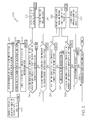
- FIG. 2 is a flow chart of a method for navigating an aircraft in accordance with an exemplary embodiment
- a monitor independently performs a cyclic redundancy check (CRC) of an identified flight path of an aircraft, for example an approach to an airport, and compares the CRC with another CRC performed on the identified flight path from a plurality of stored flight paths. If the comparison exceeds a first threshold, a first alert is provided wherein the pilot is to perform a published missed approach. If the first threshold is not exceeded, the aircraft actual flight path is determined, and a comparison of the aircraft's position determined by the FMS with the identified flight path is made. If this comparison exceeds a second threshold, a second alert and a new flight path are provided, wherein the pilot is to perform a missed approach using the new flight path. If the second threshold is not exceeded, the approach may be continued.
- CRC cyclic redundancy check
- Additional comparisons may include the actual flight path with the identified flight path, and the sensor position with a position determined by the FMS. If these thresholds are exceeded, the second alert and the new flight path are provided, wherein the pilot is to perform a missed approach using the new flight path. If these thresholds are not exceeded, the approach may be continued.
- This monitor and method provides a rating of level design assurance level B (DAL-B) or better, as defined in DO-178B, Software Considerations in Airborne Systems and Equipment Certification.
- DAL-B level design assurance level B
- an embodiment of a system or a component may employ various integrated circuit components, e.g., memory elements, digital signal processing elements, logic elements, look-up tables, or the like, which may carry out a variety of functions under the control of one or more microprocessors or other control devices.
- integrated circuit components e.g., memory elements, digital signal processing elements, logic elements, look-up tables, or the like, which may carry out a variety of functions under the control of one or more microprocessors or other control devices.
- the system 100 includes a user interface 102, a navigation computer 104 (for example, an FMS), a processor 106, one or more navigation databases 108, various optional sensors 112, various external data sources 114, and a display device 116.
- the user interface 102 and the display device 116 may be combined in the same device, for example, a touch pad.
- the user interface 102 is in operable communication with the FMS 104 and the processor 106 and is configured to receive input from a user 109 (e.g., a pilot) and, in response to the user input, supply command signals to the FMS 104 and the processor 106.
- a user 109 e.g., a pilot
- the user interface 102 may be any one, or combination, of various known user interface devices including, but not limited to, a cursor control device (not shown), such as a mouse, a trackball, or joystick, and/or a keyboard, one or more buttons, switches, or knobs.
- a cursor control device such as a mouse, a trackball, or joystick
- a keyboard such as a mouse, a trackball, or joystick
- buttons, switches, or knobs such as a keyboard, one or more buttons, switches, or knobs.
- the FMS 104 may include one of numerous known general-purpose microprocessors 103 or an application specific processor that operates in response to program instructions.
- the FMS 104 includes on-board memory 105.
- the program instructions that control the processor 103 may be stored in the memory 105. It will be appreciated that this is merely exemplary of one scheme for storing operating system software and software routines, and that various other storage schemes may be implemented. It will also be appreciated that the processor 104 may be implemented using various other circuits, not just a programmable processor. For example, digital logic circuits and analog signal processing circuits could also be used.
- the processor 106 operates to monitor the navigation of the aircraft, and is coupled to the FMS 104, GPS receiver 122 and the other avionics receivers 118.
- the processor includes memory (107) for storing instructions (software) and data from the FMS 104, GPS receiver 122, and other avionics receivers 118.
- the memory 105, 107 may be realized as RAM memory, flash memory, EPROM memory, EEPROM memory, registers, a hard disk, a removable disk, a CD-ROM, or any other form of storage medium known in the art.
- the memory 105, 107 can be coupled to the processor 103, 106, respectively, such that the processors 103, 106 can be read information from, and write information to, the memory 105, 107.
- the memory 105 may be integral to the processor 103, and the memory 107 may be integral to the processor 106.
- the processor 106 and the memory 107 may reside in an ASIC.
- a functional or logical module/component of the navigation system 100 might be realized using program code that is maintained in the memory 107.
- the processors 103, 106 may be implemented or realized with a general purpose processor, a content addressable memory, a digital signal processor, an application specific integrated circuit, a field programmable gate array, any suitable programmable logic device, discrete gate or transistor logic, discrete hardware components, or any combination designed to perform the functions described herein.
- a processor device may be realized as a microprocessor, a controller, a microcontroller, or a state machine.
- a processor device may be implemented as a combination of computing devices, e.g., a combination of a digital signal processor and a microprocessor, a plurality of microprocessors, one or more microprocessors in conjunction with a digital signal processor core, or any other such configuration.
- the processor 103 is in operable communication with the processor 106, the navigation databases 108, and the display device 116, and is coupled to receive various types of aircraft state data from the various sensors 112, and various other environment related data from the external data sources 114.
- the processor 103 is configured, in response to the inertial data and the avionics-related data, to selectively retrieve navigation data from one or more of the navigation databases 108, and to supply appropriate display commands to the display device 116.
- the display device 116 in response to the display commands from, for example, a touch screen, keypad, cursor control, line select, concentric knobs, voice control, and data link message, selectively renders various types of textual, graphic, and/or iconic information.
- the navigation databases 108 include various types of navigation-related data. These navigation-related data include various flight plan related data such as, for example, waypoints, distances between waypoints, headings between waypoints, data related to different airports, navigational aids, obstructions, special use airspace, political boundaries, communication frequencies, and aircraft approach information. It will be appreciated that, although the navigation databases 108 are, for clarity and convenience, shown as being stored separate from the FMS 104, all or portions of either or both of these databases 108 could be loaded into the memory 105, or integrally formed as part of the processor 103, and/or memory 105. The navigation databases 108 could also be part of a device or system that is physically separate from the system 100.
- the sensors 112 may be implemented using various types of sensors, systems, and or subsystems, now known or developed in the future, for supplying various types of aircraft state data.
- the state data may also vary, but preferably include data representative of the geographic position of the aircraft and also other data such as, for example, aircraft speed, heading, altitude, and attitude.
- the number and type of external data sources 114 may also vary, but typically include for example, a GPS receiver 122, other avionics receivers 118 including, for example, a VOR/ILS, and a data link unit 119.
- the other avionics receivers would include, for example, a terrain avoidance and warning system (TAWS), a traffic and collision avoidance system (TCAS), a runway awareness and advisory system (RAAS), a flight director, and a navigation computer.
- the GPS receiver 122 is a multi-channel receiver, with each channel tuned to receive one or more of the GPS broadcast signals transmitted by the constellation of GPS satellites (not illustrated) orbiting the earth. Each GPS satellite encircles the earth two times each day, and the orbits are arranged so that at least four satellites are always within line of sight from almost anywhere on the earth.
- the GPS receiver 122 upon receipt of the GPS broadcast signals from at least three, and preferably four, or more of the GPS satellites, determines the distance between the GPS receiver 122 and the GPS satellites and the position of the GPS satellites. Based on these determinations, the GPS receiver 122, using a technique known as trilateration, determines, for example, aircraft position, groundspeed, and ground track angle. These data may be supplied to the processor 104, which may determine aircraft glide slope deviation therefrom. Preferably, however, the GPS receiver 122 is configured to determine, and supply data representative of, aircraft glide slope deviation to the processor 104.
- the display device 116 in response to display commands supplied from the processor 104, selectively renders various textual, graphic, and/or iconic information, and thereby supply visual feedback to the user 109.
- the display device 116 may be implemented using any one of numerous known display devices suitable for rendering textual, graphic, and/or iconic information in a format viewable by the user 109.
- Non-limiting examples of such display devices include various cathode ray tube (CRT) displays, and various flat panel displays such as various types of LCD (liquid crystal display) and TFT (thin film transistor) displays.
- the display device 116 may additionally be implemented as a panel mounted display, a HUD (head-up display) projection, or any one of numerous known technologies.
- the display device 116 may be configured as any one of numerous types of aircraft flight deck displays. For example, it may be configured as a multi-function display, a horizontal situation indicator, or a vertical situation indicator, just to name a few. In the depicted embodiment, however, the display device 116 is configured as a primary flight display (PFD).
- PFD primary flight display
- the display device 116 is also configured to process the current flight status data for the host aircraft.
- the sources of flight status data generate, measure, and/or provide different types of data related to the operational status of the host aircraft, the environment in which the host aircraft is operating, flight parameters, and the like.
- the sources of flight status data may be realized using line replaceable units (LRUs), transducers, accelerometers, instruments, sensors, and other well known devices.
- LRUs line replaceable units
- the data provided by the sources of flight status data may include, without limitation: airspeed data; groundspeed data; altitude data; attitude data, including pitch data and roll data; yaw data; geographic position data, such as GPS data; time/date information; heading information; weather information; flight path data; track data; radar altitude data; geometric altitude data; wind speed data; wind direction data; etc.
- the display device 116 is suitably designed to process data obtained from the sources of flight status data in the manner described in more detail herein. In particular, the display device 116 can use the flight status data of the host aircraft when rendering the SVS display.
- Onboard data link 119 is coupled to external data link 120 and is configured to receive data from ground stations and other aircraft. Examples of the data received include, for example, weather information, traffic information, route changes, and clearances and alerts (including NOTAMS).
- the onboard data link unit 119 receives navigation routes, for example, approaches to an airport, and a cyclic redundancy check (CRC) for each of the navigation routes.
- CRC cyclic redundancy check
- FIG. 2 is a flow chart that illustrates an exemplary embodiment of a navigation process 200 suitable for use with a flight deck display system such as the navigation system 100.
- Process 200 represents one implementation of a method for displaying aircraft traffic information on an onboard display element of a host aircraft.
- the various tasks performed in connection with process 200 may be performed by software, hardware, firmware, or any combination thereof.
- the following description of process 200 may refer to elements mentioned above in connection with FIG. 1 .
- portions of process 200 may be performed by different elements of the described system, e.g., a processor, a display element, or a data communication component. It should be appreciated that process 200 may include any number of additional or alternative tasks, the tasks shown in FIG.
- process 200 need not be performed in the illustrated order, and process 200 may be incorporated into a more comprehensive procedure or process having additional functionality not described in detail herein. Moreover, one or more of the tasks shown in FIG. 2 could be omitted from an embodiment of the process 200 as long as the intended overall functionality remains intact.
- the method includes computing 202 a first cyclic redundancy check (CRC) for each of a plurality of flight paths, for example, approaches to airports.
- This step 202 is preferably accomplished on the ground and provided to the aircraft typically once every 28 days.
- the flight paths and the first CRCs are stored 204 in the FMS 104 of the aircraft.
- a desired flight path is identified 206 (which may be accomplished by a stored flight plan in the FMS 104 or selected by the pilot), and a second CRC is calculated 208 in the processor 106 for the identified flight path.
- a first alert is provided 212 to the display 116 and optionally to the speaker 117, wherein the pilot would initiate 214 the published missed approach.
- the FMS 104 determines 220 an actual flight path, and if 222 a comparison 218 of the defined flight path with the high integrity flight path by the processor 106 does not exceed a second threshold 218, if 224 the FMS 104 information is available, and if 226 the high integrity flight path is not completed, the comparison 216 is repeated. If any of the second, third, and fourth thresholds are exceeded, the second alert signal and the high integrity flight path are provided 228 to the display 116 and optionally to the speaker 117. The pilot would then execute 230 a missed approach using the high integrity flight path.
- the monitor includes creation of a data entry, FMS functions, and a monitoring function.
- the data entry is the generation of the navigation database for the FMS 104. This data entry preferably happens every 28 days and includes a new storage element, called an RNP Final Approach Segment (RFAS) datablock.
- RFAS RNP Final Approach Segment
- the process that generates 202 the navigation database will collect the waypoints and legs of a plurality of final approach segment flight paths and store 204 them separately in the RFAS datablock.
- the process will also compute 208 a cyclic redundancy check (CRC) based on the contents of the RFAS datablock and append the resultant value to the RFAS datablock.
- CRC cyclic redundancy check
- the RFAS datablock represents a high-integrity data representation of at least a portion of the flightplan, for example, the final approach portion. It is preferred the RFAS datablock is created for each approach in the database that makes use of the monitoring function, and preferably an RFAS datablock will be generated for each low RNP minimum within an RNP approach.
- the data entry creating 202 the RFAS datablock is loaded prior to a flight (when the navigation database is created).
- Data included in the RFAS data block may include for each airport at least one runway, a route type, an RNP level requirement, final approach fix latitude and longitude, the number of legs between the final approach fix and the missed approach point, the calculated CRC, and for each leg: leg type, for example, track-to-fix or radius-to-fix, waypoint latitude and longitude, arc center latitude and longitude, radius, and turn direction.
- the FMS stores 204 the navigation database including the RFAS datablock.
- the FMS will make the RFAS datablock available via a databus.
- the monitoring function will read the RFAS datablock that has been posted on the databus, compute 208 the CRC of the data using the same algorithm as the database generator element, and will compare 210 the results of this computation with the CRC value embedded in the RFAS datablock. If the values do not agree, then it is concluded the data in the RFAS datablock has been corrupted and the monitor cannot be used for the approach. Assuming the CRC comparison agrees, the monitoring function will use the aircraft position from navigation sensors, for example, the GPS or ILS, and compute the aircraft position along the flight path, for example, the final approach course, as described in the RFAS datablock. From this the monitoring function will compute the cross-track deviation from the final approach course.
- the monitor may issue 228 an alarm when the cross-track value exceeds a given value, e.g., the RNP value of the approach (which is listed in units of nautical miles), or the monitor may issue an alarm after the cross-track value is compared to a different cross-track value, for example, the crosstrack value computed by the FMS, and the difference is found to exceed a threshold.
- the monitor could issue an alarm for either condition.
- the monitor determines an alarm condition has been detected, it will alert the crew through the crew interface (a display and optionally, an audio signal).
- the preferred embodiment includes five states that the display and monitor function may display to the aircrew.
- State 1 the monitor and display function are not active (the approach field is displayed in a first format, for example, white).
- State 2 the monitor and display function indicate the system is within tolerance during the approach segment (displayed in a second format, for example, green).
- State 3 the monitor and display function cannot support the selected minimums (displayed in a third format, for example, yellow), for which the aircrew may continue the approach to an alternate minimum or execute a missed approach.
- State 4 the monitor and display function indicate a missed approach because the system cannot support any minimums for the selected approach (displayed in a fourth format, for example, orange).
- the system When an approach has been loaded into the FMS, the system will transition to state 1 when the approach is selected. The system will transition to state 0 if the aircrew initiates a missed approach, changes the destination or approach, or completes the approach. The system will transition to state 3 if the minimum is a low-RNP value and the desired minimum is available, and to state 4 if the desired minimum is not available.
- the display function will initiate an alarm if a threshold is exceeded in one of several situations, for example, position estimation, path steering, path definition, and FMS health.
- a position estimation algorithm will compute the absolute distance between the FMS position and the raw sensor (GPS or Hybrid IRS) position.
- the alarm threshold will be the computed distance compared to the greater of 1.5 times the current figure of merit (FOM) of the sensor and 1.0 times the current RNP value.
- FOM current figure of merit
- a path steering algorithm will compute the crosstrack distance between the raw sensor position and the monitor-computed path centerline of the approach.
- the alarm threshold will be the computed distance compared to the greater of 1.5 times the current RNP value. This alarm algorithm will only be active if the autopilot is engaged and the lateral flight-director mode is LNAV.
- a path definition algorithm will compute the delta distance between the FMS current-leg crosstrack error and the monitor-computed cross-track error.
- the alarm threshold will be the greater of 1.5 times the current FOM ( Figure Of Merit) of the sensor and 1.0 times the current RNP value.
- a FMS health algorithm will monitor key output data from the FMS. If that data is not fresh and valid for 6 seconds, the alarm threshold will be met.
Landscapes
- Engineering & Computer Science (AREA)
- Radar, Positioning & Navigation (AREA)
- Remote Sensing (AREA)
- Aviation & Aerospace Engineering (AREA)
- Physics & Mathematics (AREA)
- General Physics & Mathematics (AREA)
- Traffic Control Systems (AREA)
- Navigation (AREA)
- Position Fixing By Use Of Radio Waves (AREA)
Applications Claiming Priority (1)
| Application Number | Priority Date | Filing Date | Title |
|---|---|---|---|
| US13/547,167 US9097529B2 (en) | 2012-07-12 | 2012-07-12 | Aircraft system and method for improving navigation performance |
Publications (2)
| Publication Number | Publication Date |
|---|---|
| EP2685218A2 true EP2685218A2 (de) | 2014-01-15 |
| EP2685218A3 EP2685218A3 (de) | 2016-03-23 |
Family
ID=48672483
Family Applications (1)
| Application Number | Title | Priority Date | Filing Date |
|---|---|---|---|
| EP13173676.1A Ceased EP2685218A3 (de) | 2012-07-12 | 2013-06-25 | Flugzeugsystem und Verfahren zur Verbesserung der Navigationsleistung |
Country Status (3)
| Country | Link |
|---|---|
| US (1) | US9097529B2 (de) |
| EP (1) | EP2685218A3 (de) |
| CN (1) | CN103543749B (de) |
Cited By (4)
| Publication number | Priority date | Publication date | Assignee | Title |
|---|---|---|---|---|
| FR3028975A1 (fr) * | 2014-11-26 | 2016-05-27 | Thales Sa | Procede de detection d'erreur d'un systeme de gestion de vol et de guidage d'un aeronef et syteme de gestion de vol et de guidage a haute integrite |
| CN112715508A (zh) * | 2020-12-15 | 2021-04-30 | 广州极飞科技有限公司 | 确定下料口位置的方法和装置 |
| CN114415728A (zh) * | 2022-01-21 | 2022-04-29 | 广东汇天航空航天科技有限公司 | 飞行汽车的控制方法、装置、交通工具及存储介质 |
| WO2022185002A1 (fr) * | 2021-03-02 | 2022-09-09 | Safran Electronics & Defense | Procédé et centrale de calcul de données de navigation inertielle |
Families Citing this family (25)
| Publication number | Priority date | Publication date | Assignee | Title |
|---|---|---|---|---|
| US8862290B1 (en) * | 2013-04-18 | 2014-10-14 | Ge Aviation Systems Llc | Flight system for an aircraft having an autoland system |
| US9746562B2 (en) * | 2014-06-30 | 2017-08-29 | The Boeing Company | Portable ground based augmentation system |
| US9688416B2 (en) * | 2014-10-20 | 2017-06-27 | Honeywell International Inc | System and method for isolating attitude failures in aircraft |
| CN105059557B (zh) * | 2015-08-07 | 2018-04-10 | 中国商用飞机有限责任公司 | 所需导航性能(rnp)显示方法和设备 |
| FR3044758B1 (fr) * | 2015-12-08 | 2018-01-12 | Airbus Operations | Ensemble de gestion de vol d’un aeronef et procede de surveillance de consignes de guidage d’un tel ensemble. |
| CN106054915A (zh) | 2016-05-24 | 2016-10-26 | 北京小米移动软件有限公司 | 无人机的控制方法及装置 |
| CN106403995B (zh) * | 2016-08-26 | 2019-08-06 | 中国航空无线电电子研究所 | 一种用于rnp机载性能监视与告警的装置 |
| EP3855270A1 (de) * | 2016-11-14 | 2021-07-28 | SZ DJI Technology Co., Ltd. | Flugbahnbestimmung |
| DE102016015689B4 (de) * | 2016-12-23 | 2026-02-12 | Mbda Deutschland Gmbh | Flugpfadbestimmungsvorrichtung und Flugpfadbestimmungsverfahren |
| US10386202B2 (en) * | 2017-02-17 | 2019-08-20 | The Charles Stark Draper Laboratory, Inc. | Systems and methods for determining quality and integrity of source information to determine navigation information of an object |
| US11043132B1 (en) | 2017-02-17 | 2021-06-22 | The Charles Stark Draper Laboratory, Inc. | Systems and methods for determining quality and integrity of source information to determine navigation information of an object |
| US11774602B1 (en) | 2017-04-24 | 2023-10-03 | The Charles Stark Draper Laboratory, Inc. | Multi-source distributed navigation system architecture |
| US11079757B1 (en) * | 2017-11-20 | 2021-08-03 | Amazon Technologies, Inc. | Unmanned aerial vehicles to survey locations and collect data about different signal sources |
| US20200013243A1 (en) * | 2018-07-03 | 2020-01-09 | Honeywell International Inc. | Systems and methods for enhanced cyber security by data corruption detection monitoring |
| US10861341B2 (en) * | 2018-12-11 | 2020-12-08 | Honeywell International Inc. | Method and system for prompting aircraft task reminders |
| US11024187B2 (en) * | 2018-12-19 | 2021-06-01 | The Boeing Company | Aircraft positioning on a taxiway |
| EP3719777B1 (de) * | 2019-04-03 | 2025-07-30 | Honeywell International Inc. | Systeme und verfahren zur überwachung und identifizierung von fehlern in dualen flugmanagementsystemen |
| US11222548B2 (en) * | 2019-05-08 | 2022-01-11 | The Boeing Company | Navigation performance in urban air vehicles |
| US11379344B2 (en) * | 2019-06-26 | 2022-07-05 | Honeywell International Inc. | Method to assure integrity of integrated certified and non-certified sensors |
| CN110798661A (zh) * | 2019-10-16 | 2020-02-14 | 中国航空工业集团公司洛阳电光设备研究所 | 一种平视显示器非等角符号完整性监控系统及监控方法 |
| CN111080144A (zh) * | 2019-12-20 | 2020-04-28 | 西安靖轩航空科技有限公司 | 一种智能感知的机场保障能力实时评估系统及评估方法 |
| US12126427B2 (en) | 2020-07-20 | 2024-10-22 | The Board Of Regents Of The University Of Oklahoma | VHF-omnidirectional range/instrument landing system receiver and methods of use |
| US11645928B2 (en) | 2020-09-28 | 2023-05-09 | Honeywell International Inc. | Method of using multiple approach guidance systems to provide higher integrity with improved performance and availability |
| CN113703419B (zh) * | 2021-08-08 | 2024-05-17 | 中国航空工业集团公司沈阳飞机设计研究所 | 一种飞行控制系统余度管理算法的自动测试方法及装置 |
| CN119094009B (zh) * | 2024-11-08 | 2025-11-04 | 之江实验室 | 一种卫星组网构建方法、装置、介质以及设备 |
Family Cites Families (36)
| Publication number | Priority date | Publication date | Assignee | Title |
|---|---|---|---|---|
| US4806940A (en) * | 1986-04-30 | 1989-02-21 | Honeywell Inc. | Navigation mode selection apparatus |
| US5771484A (en) * | 1996-02-28 | 1998-06-23 | Sun Microsystems, Inc. | Automated positive control traffic system for weather |
| US5884223A (en) * | 1996-04-29 | 1999-03-16 | Sun Microsystems, Inc. | Altitude sparse aircraft display |
| US5872526A (en) * | 1996-05-23 | 1999-02-16 | Sun Microsystems, Inc. | GPS collision avoidance system |
| US5703591A (en) * | 1996-06-03 | 1997-12-30 | Sun Microsystems, Inc. | Aircraft N-number control system |
| US5906657A (en) * | 1996-07-01 | 1999-05-25 | Sun Microsystems, Inc. | System using position detector to determine location and orientation between computers to select information to be transferred via wireless medium |
| US6118401A (en) * | 1996-07-01 | 2000-09-12 | Sun Microsystems, Inc. | Aircraft ground collision avoidance system and method |
| US6278965B1 (en) * | 1998-06-04 | 2001-08-21 | The United States Of America As Represented By The Administrator Of The National Aeronautics And Space Administration | Real-time surface traffic adviser |
| US7131136B2 (en) * | 2002-07-10 | 2006-10-31 | E-Watch, Inc. | Comprehensive multi-media surveillance and response system for aircraft, operations centers, airports and other commercial transports, centers and terminals |
| US6259977B1 (en) * | 1998-11-17 | 2001-07-10 | Austin Digital Inc. | Aircraft flight data analysis system and method |
| WO2002008057A1 (en) * | 2000-07-20 | 2002-01-31 | Kapadia Viraf S | System and method for transportation vehicle monitoring, feedback and control |
| US6606035B2 (en) * | 2000-11-17 | 2003-08-12 | Safe Landing Systems Inc. | System and method for airport runway monitoring |
| US6571155B2 (en) | 2001-07-02 | 2003-05-27 | The Boeing Company | Assembly, computer program product and method for displaying navigation performance based flight path deviation information |
| WO2003038750A2 (en) * | 2001-10-30 | 2003-05-08 | Polydimension, Inc. | Method and apparatus for utilizing representational images in analytical activities |
| BR0304563A (pt) * | 2002-05-07 | 2004-07-06 | Argo Tech Corp | Sistema de rastreamento e método associado |
| US20030225492A1 (en) * | 2002-05-29 | 2003-12-04 | Cope Gary G. | Flight data transmission via satellite link and ground storage of data |
| US6763289B2 (en) * | 2002-07-19 | 2004-07-13 | The Boeing Company | System, bypass apparatus and method of operating a store of a first predetermined type |
| ITBO20020724A1 (it) * | 2002-11-15 | 2004-05-16 | L E A T S R L | Metodo e sistema per l'acquisizione e la registrazione di dati relativi allo spostamento di un veicolo |
| US7735005B2 (en) * | 2003-09-11 | 2010-06-08 | The Boeing Company | Style guide and formatting methods for pilot quick reference handbooks |
| US7685384B2 (en) * | 2004-02-06 | 2010-03-23 | Globalscape, Inc. | System and method for replicating files in a computer network |
| WO2006011141A2 (en) * | 2004-07-25 | 2006-02-02 | Israel Aerospace Industries Ltd. | Method and system for the acquisition of data and for the display of data |
| US7353090B2 (en) * | 2004-10-04 | 2008-04-01 | The Boeing Company | System, bus monitor assembly and method of monitoring at least one data bus of an aircraft |
| DE05858477T1 (de) * | 2004-11-08 | 2008-01-31 | Bell Helicopter Textron, Inc., Fort Worth | Flugsteuerungssystem mit dreifachem steuerkreisdesign |
| FR2887329B1 (fr) * | 2005-06-21 | 2007-08-03 | Airbus France Sas | Procede et dispositif d'affichage pour un aeronef qui suit un plan de vol |
| FR2888636B1 (fr) * | 2005-07-13 | 2007-09-28 | Airbus France Sas | Dispositif d'aide a une approche avec guidage vertical pour aeronef |
| US20070219831A1 (en) * | 2005-08-15 | 2007-09-20 | Ne Meth Louis G | Flight risk management system |
| FR2896071A1 (fr) * | 2006-01-11 | 2007-07-13 | Airbus France Sas | Procede et dispositif d'aide au pilotage d'un aeronef lors d'une approche autonome. |
| US7555372B2 (en) * | 2006-04-21 | 2009-06-30 | Honeywell International Inc. | Method and apparatus to display landing performance data |
| US8160758B2 (en) * | 2006-05-22 | 2012-04-17 | Honeywell International Inc. | Methods and systems for radar aided aircraft positioning for approaches and landings |
| FR2901893B1 (fr) | 2006-06-06 | 2008-09-12 | Airbus France Sas | Dispositif de surveillance d'informations de commande d'un aeronef |
| US8027756B2 (en) | 2006-12-07 | 2011-09-27 | The Boeing Company | Integrated approach navigation system, method, and computer program product |
| US8718931B2 (en) * | 2007-10-31 | 2014-05-06 | The Boeing Company | Method and apparatus for cross checking required navigation performance procedures |
| TW200926709A (en) * | 2007-12-03 | 2009-06-16 | Inst Information Industry | Network address assignment method and routing method for a long thin ZigBee network |
| US8494693B2 (en) | 2009-08-05 | 2013-07-23 | The Boeing Company | Vertical required navigation performance containment with radio altitude |
| US20110246002A1 (en) * | 2010-04-02 | 2011-10-06 | Cloudahoy Inc. | Systems and methods for aircraft flight tracking and analysis |
| US8972083B2 (en) * | 2011-08-18 | 2015-03-03 | Pc Krause And Associates, Inc. | System and method for aircraft thermal capacity prediction |
-
2012
- 2012-07-12 US US13/547,167 patent/US9097529B2/en active Active
-
2013
- 2013-06-25 EP EP13173676.1A patent/EP2685218A3/de not_active Ceased
- 2013-07-11 CN CN201310290332.3A patent/CN103543749B/zh not_active Expired - Fee Related
Non-Patent Citations (1)
| Title |
|---|
| None |
Cited By (9)
| Publication number | Priority date | Publication date | Assignee | Title |
|---|---|---|---|---|
| FR3028975A1 (fr) * | 2014-11-26 | 2016-05-27 | Thales Sa | Procede de detection d'erreur d'un systeme de gestion de vol et de guidage d'un aeronef et syteme de gestion de vol et de guidage a haute integrite |
| CN105632246A (zh) * | 2014-11-26 | 2016-06-01 | 泰勒斯公司 | 飞行器飞行管理和引导系统以及高完整性飞行管理和引导系统的误差检测方法 |
| US9575489B2 (en) | 2014-11-26 | 2017-02-21 | Thales | Method of error detection of an aircraft flight management and guidance system and high-integrity flight management and guidance system |
| CN105632246B (zh) * | 2014-11-26 | 2020-06-26 | 泰勒斯公司 | 飞行器飞行管理和引导系统及其误差检测方法 |
| CN112715508A (zh) * | 2020-12-15 | 2021-04-30 | 广州极飞科技有限公司 | 确定下料口位置的方法和装置 |
| WO2022185002A1 (fr) * | 2021-03-02 | 2022-09-09 | Safran Electronics & Defense | Procédé et centrale de calcul de données de navigation inertielle |
| FR3120437A1 (fr) * | 2021-03-02 | 2022-09-09 | Safran Electronics & Defense | Procede et centrale de calcul de donnees de navigation inertielle |
| CN114415728A (zh) * | 2022-01-21 | 2022-04-29 | 广东汇天航空航天科技有限公司 | 飞行汽车的控制方法、装置、交通工具及存储介质 |
| CN114415728B (zh) * | 2022-01-21 | 2023-11-03 | 广东汇天航空航天科技有限公司 | 飞行汽车的控制方法、装置、交通工具及存储介质 |
Also Published As
| Publication number | Publication date |
|---|---|
| EP2685218A3 (de) | 2016-03-23 |
| US20140019038A1 (en) | 2014-01-16 |
| CN103543749A (zh) | 2014-01-29 |
| CN103543749B (zh) | 2018-06-26 |
| US9097529B2 (en) | 2015-08-04 |
Similar Documents
| Publication | Publication Date | Title |
|---|---|---|
| US9097529B2 (en) | Aircraft system and method for improving navigation performance | |
| US8589071B2 (en) | Aircraft vision system including a runway position indicator | |
| US9640081B2 (en) | System and method for displaying a runway position indicator | |
| US9499279B2 (en) | System and method for displaying runway approach information | |
| US10214300B2 (en) | System and method for displaying runway overrun information | |
| CN105549938B (zh) | 用于显示跑道着陆信息的系统和方法 | |
| CN106017505B (zh) | 飞行器合成视觉系统及操作方法 | |
| US20130041529A1 (en) | Aircraft vision system having redundancy for low altitude approaches | |
| US8718931B2 (en) | Method and apparatus for cross checking required navigation performance procedures | |
| US8392039B2 (en) | Method and system displaying crosswind correction for approach to a runway | |
| US20110025530A1 (en) | Method and system displaying a flight path to intercept an ils glide path | |
| EP2775469B1 (de) | System und Verfahren zur Verwaltung eines Intervalls zwischen Flugzeugen | |
| US9159241B1 (en) | Methods, systems, and apparatus for synthetic instrument landing system (SILS) | |
| EP2980772B1 (de) | System und verfahren zur automatischen identifizierung von angezeigtem, von der flugsicherung erwähntem verkehr | |
| US9875659B2 (en) | System and method for exocentric display of integrated navigation | |
| EP4239293A1 (de) | Systeme und verfahren zur konstruktion von geländeentwussten kundenspezifischen verfahren | |
| US8938356B1 (en) | Tactical flight data validating systems and methods for a multi-channel topological architecture | |
| US12175879B2 (en) | Systems and methods for constructing terrain deconflicted custom procedures |
Legal Events
| Date | Code | Title | Description |
|---|---|---|---|
| PUAI | Public reference made under article 153(3) epc to a published international application that has entered the european phase |
Free format text: ORIGINAL CODE: 0009012 |
|
| 17P | Request for examination filed |
Effective date: 20130625 |
|
| AK | Designated contracting states |
Kind code of ref document: A2 Designated state(s): AL AT BE BG CH CY CZ DE DK EE ES FI FR GB GR HR HU IE IS IT LI LT LU LV MC MK MT NL NO PL PT RO RS SE SI SK SM TR |
|
| AX | Request for extension of the european patent |
Extension state: BA ME |
|
| RAP1 | Party data changed (applicant data changed or rights of an application transferred) |
Owner name: HONEYWELL INTERNATIONAL INC. |
|
| PUAL | Search report despatched |
Free format text: ORIGINAL CODE: 0009013 |
|
| AK | Designated contracting states |
Kind code of ref document: A3 Designated state(s): AL AT BE BG CH CY CZ DE DK EE ES FI FR GB GR HR HU IE IS IT LI LT LU LV MC MK MT NL NO PL PT RO RS SE SI SK SM TR |
|
| AX | Request for extension of the european patent |
Extension state: BA ME |
|
| RIC1 | Information provided on ipc code assigned before grant |
Ipc: G01C 23/00 20060101AFI20160216BHEP |
|
| 17Q | First examination report despatched |
Effective date: 20160309 |
|
| APBK | Appeal reference recorded |
Free format text: ORIGINAL CODE: EPIDOSNREFNE |
|
| APBN | Date of receipt of notice of appeal recorded |
Free format text: ORIGINAL CODE: EPIDOSNNOA2E |
|
| APAF | Appeal reference modified |
Free format text: ORIGINAL CODE: EPIDOSCREFNE |
|
| APAX | Date of receipt of notice of appeal deleted |
Free format text: ORIGINAL CODE: EPIDOSDNOA2E |
|
| APBK | Appeal reference recorded |
Free format text: ORIGINAL CODE: EPIDOSNREFNE |
|
| APBN | Date of receipt of notice of appeal recorded |
Free format text: ORIGINAL CODE: EPIDOSNNOA2E |
|
| APBT | Appeal procedure closed |
Free format text: ORIGINAL CODE: EPIDOSNNOA9E |
|
| STAA | Information on the status of an ep patent application or granted ep patent |
Free format text: STATUS: THE APPLICATION HAS BEEN REFUSED |
|
| 18R | Application refused |
Effective date: 20190531 |
|
| P01 | Opt-out of the competence of the unified patent court (upc) registered |
Effective date: 20230525 |