EP2685068B1 - Steuerungssystem und Verfahren zur steuerung einer Gasturbine zur Flugzeugleistungsversorgung - Google Patents
Steuerungssystem und Verfahren zur steuerung einer Gasturbine zur Flugzeugleistungsversorgung Download PDFInfo
- Publication number
- EP2685068B1 EP2685068B1 EP13173975.7A EP13173975A EP2685068B1 EP 2685068 B1 EP2685068 B1 EP 2685068B1 EP 13173975 A EP13173975 A EP 13173975A EP 2685068 B1 EP2685068 B1 EP 2685068B1
- Authority
- EP
- European Patent Office
- Prior art keywords
- engine
- power
- control signal
- outtake
- measurement
- Prior art date
- Legal status (The legal status is an assumption and is not a legal conclusion. Google has not performed a legal analysis and makes no representation as to the accuracy of the status listed.)
- Active
Links
Images





Classifications
-
- F—MECHANICAL ENGINEERING; LIGHTING; HEATING; WEAPONS; BLASTING
- F02—COMBUSTION ENGINES; HOT-GAS OR COMBUSTION-PRODUCT ENGINE PLANTS
- F02C—GAS-TURBINE PLANTS; AIR INTAKES FOR JET-PROPULSION PLANTS; CONTROLLING FUEL SUPPLY IN AIR-BREATHING JET-PROPULSION PLANTS
- F02C9/00—Controlling gas-turbine plants; Controlling fuel supply in air- breathing jet-propulsion plants
- F02C9/26—Control of fuel supply
- F02C9/28—Regulating systems responsive to plant or ambient parameters, e.g. temperature, pressure, rotor speed
-
- B—PERFORMING OPERATIONS; TRANSPORTING
- B64—AIRCRAFT; AVIATION; COSMONAUTICS
- B64D—EQUIPMENT FOR FITTING IN OR TO AIRCRAFT; FLIGHT SUITS; PARACHUTES; ARRANGEMENT OR MOUNTING OF POWER PLANTS OR PROPULSION TRANSMISSIONS IN AIRCRAFT
- B64D31/00—Power plant control systems; Arrangement of power plant control systems in aircraft
- B64D31/02—Initiating means
- B64D31/06—Initiating means actuated automatically
-
- F—MECHANICAL ENGINEERING; LIGHTING; HEATING; WEAPONS; BLASTING
- F01—MACHINES OR ENGINES IN GENERAL; ENGINE PLANTS IN GENERAL; STEAM ENGINES
- F01D—NON-POSITIVE DISPLACEMENT MACHINES OR ENGINES, e.g. STEAM TURBINES
- F01D21/00—Shutting-down of machines or engines, e.g. in emergency; Regulating, controlling, or safety means not otherwise provided for
- F01D21/003—Arrangements for testing or measuring
-
- F—MECHANICAL ENGINEERING; LIGHTING; HEATING; WEAPONS; BLASTING
- F02—COMBUSTION ENGINES; HOT-GAS OR COMBUSTION-PRODUCT ENGINE PLANTS
- F02C—GAS-TURBINE PLANTS; AIR INTAKES FOR JET-PROPULSION PLANTS; CONTROLLING FUEL SUPPLY IN AIR-BREATHING JET-PROPULSION PLANTS
- F02C7/00—Features, components parts, details or accessories, not provided for in, or of interest apart form groups F02C1/00 - F02C6/00; Air intakes for jet-propulsion plants
- F02C7/04—Air intakes for gas-turbine plants or jet-propulsion plants
- F02C7/042—Air intakes for gas-turbine plants or jet-propulsion plants having variable geometry
-
- F—MECHANICAL ENGINEERING; LIGHTING; HEATING; WEAPONS; BLASTING
- F02—COMBUSTION ENGINES; HOT-GAS OR COMBUSTION-PRODUCT ENGINE PLANTS
- F02C—GAS-TURBINE PLANTS; AIR INTAKES FOR JET-PROPULSION PLANTS; CONTROLLING FUEL SUPPLY IN AIR-BREATHING JET-PROPULSION PLANTS
- F02C9/00—Controlling gas-turbine plants; Controlling fuel supply in air- breathing jet-propulsion plants
- F02C9/26—Control of fuel supply
-
- F—MECHANICAL ENGINEERING; LIGHTING; HEATING; WEAPONS; BLASTING
- F02—COMBUSTION ENGINES; HOT-GAS OR COMBUSTION-PRODUCT ENGINE PLANTS
- F02C—GAS-TURBINE PLANTS; AIR INTAKES FOR JET-PROPULSION PLANTS; CONTROLLING FUEL SUPPLY IN AIR-BREATHING JET-PROPULSION PLANTS
- F02C9/00—Controlling gas-turbine plants; Controlling fuel supply in air- breathing jet-propulsion plants
- F02C9/48—Control of fuel supply conjointly with another control of the plant
- F02C9/50—Control of fuel supply conjointly with another control of the plant with control of working fluid flow
- F02C9/54—Control of fuel supply conjointly with another control of the plant with control of working fluid flow by throttling the working fluid, by adjusting vanes
-
- G—PHYSICS
- G05—CONTROLLING; REGULATING
- G05B—CONTROL OR REGULATING SYSTEMS IN GENERAL; FUNCTIONAL ELEMENTS OF SUCH SYSTEMS; MONITORING OR TESTING ARRANGEMENTS FOR SUCH SYSTEMS OR ELEMENTS
- G05B13/00—Adaptive control systems, i.e. systems automatically adjusting themselves to have a performance which is optimum according to some preassigned criterion
- G05B13/02—Adaptive control systems, i.e. systems automatically adjusting themselves to have a performance which is optimum according to some preassigned criterion electric
- G05B13/0205—Adaptive control systems, i.e. systems automatically adjusting themselves to have a performance which is optimum according to some preassigned criterion electric not using a model or a simulator of the controlled system
- G05B13/024—Adaptive control systems, i.e. systems automatically adjusting themselves to have a performance which is optimum according to some preassigned criterion electric not using a model or a simulator of the controlled system in which a parameter or coefficient is automatically adjusted to optimise the performance
-
- F—MECHANICAL ENGINEERING; LIGHTING; HEATING; WEAPONS; BLASTING
- F05—INDEXING SCHEMES RELATING TO ENGINES OR PUMPS IN VARIOUS SUBCLASSES OF CLASSES F01-F04
- F05D—INDEXING SCHEME FOR ASPECTS RELATING TO NON-POSITIVE-DISPLACEMENT MACHINES OR ENGINES, GAS-TURBINES OR JET-PROPULSION PLANTS
- F05D2220/00—Application
- F05D2220/30—Application in turbines
- F05D2220/32—Application in turbines in gas turbines
- F05D2220/323—Application in turbines in gas turbines for aircraft propulsion, e.g. jet engines
-
- F—MECHANICAL ENGINEERING; LIGHTING; HEATING; WEAPONS; BLASTING
- F05—INDEXING SCHEMES RELATING TO ENGINES OR PUMPS IN VARIOUS SUBCLASSES OF CLASSES F01-F04
- F05D—INDEXING SCHEME FOR ASPECTS RELATING TO NON-POSITIVE-DISPLACEMENT MACHINES OR ENGINES, GAS-TURBINES OR JET-PROPULSION PLANTS
- F05D2260/00—Function
- F05D2260/83—Testing, e.g. methods, components or tools therefor
-
- F—MECHANICAL ENGINEERING; LIGHTING; HEATING; WEAPONS; BLASTING
- F05—INDEXING SCHEMES RELATING TO ENGINES OR PUMPS IN VARIOUS SUBCLASSES OF CLASSES F01-F04
- F05D—INDEXING SCHEME FOR ASPECTS RELATING TO NON-POSITIVE-DISPLACEMENT MACHINES OR ENGINES, GAS-TURBINES OR JET-PROPULSION PLANTS
- F05D2270/00—Control
- F05D2270/01—Purpose of the control system
- F05D2270/05—Purpose of the control system to affect the output of the engine
- F05D2270/053—Explicitly mentioned power
Definitions
- the application relates generally to a system and method for aircraft power outtake management and engine control.
- the present invention further provides a method for controlling a gas turbine engine supplying power to an aircraft, as defined in claim 8.
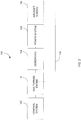
- the system 100 illustratively comprises a control system 102 for controlling the gas turbine engine 10, a generator 104 driven by the gas turbine engine 10, a power system 106 coupled to the generator 104, and at least one aircraft load 108.
- the gas turbine engine 10 which illustratively receives as input control signals from the control system 102, may be arranged to drive the generator 104 via a rotating shaft, spool, or the like.
- the generator 104 may be an electrical generator, a gas generator, a hydraulic pump, or any other generator suitable for supplying energy to the power system 104 to power the aircraft, as known to those skilled in the art.
- the generator 104 is connected to the power system 106, which may comprise a network of electrically, mechanically, or hydraulically connected machines and devices (not shown).
- the demands of such devices are illustratively represented collectively as aircraft loads 108, which draw power from the power system 106 via a power distribution bus (not shown), such as an AC or DC power bus, or the like.
- the aircraft loads 108 may be attributed to machines and devices, such as aircraft navigational equipment, safety equipment, communication equipment, lighting and multimedia equipment, cabin heating and ventilation, aircraft or engine controls, or the like.
- the amount of power drawn or consumed by the aircraft loads 108 may be monitored by a device (not shown), such as a sensor, and fed directly to the control system 102, either in a wired manner or wirelessly over a suitable network (not shown).
- the information is transmitted to the control system 102 in a wired manner using a direct link 110, such as a wire, to connect the control system 102 to the aircraft loads 108.
- the power outtake of the aircraft loads 108 may be received at the control system 102 in real-time during a flight and acted upon to enhance the performance, stability, and reliability of the turbine engine 10 as well as control the amount of power drawn from the power system 106 by the aircraft loads 108, as will be described further below.
- pneumatic or hydraulic systems may be pressurized with pumps mechanically driven by the engine 10 for a variety of aircraft applications, such as operating wheel brakes, retractable landing gear, or constant-speed propellers.
- the power outtake may also result from pressurized bleed air, which may be drawn off the compressor section 12 of the engine 10 and used for pressurization, cooling, and/or heating of the aircraft. It will be understood that other power outtakes may apply.
- the power outtake may further result from use of a mechanical winch coupled to the engine 10 through the reduction gearbox with a clutching system. Such a winch may be used to haul back rescuees to helicopters during search and rescue missions. It will also be understood that combinations of power outtakes, e.g. electrical and mechanical, may apply.
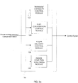
- Fig. 3a is an exemplary embodiment of the control system 102.
- the power outtake from the aircraft loads 108 is illustratively received by a receiving module or unit 112, which produces an output that is either transmitted to a comparison module 114 or directly to a command generation module 116.
- the received power outtake data may be sent to the comparison module 114 for comparing the current power outtake reading to a predetermined threshold fixed by the engine manufacturer for optimal performance of the engine 10. It may therefore be possible to determine whether the current power outtake reading is higher or lower than the threshold.
- the comparison module 114 may also compare the current power outtake to a previous power outtake reading, which may be stored in a memory, to identify an increase or decrease in power outtake drawn by the aircraft loads 108.
- Fig. 3b illustrates the command generation module 116 in more detail.
- the command generation module 116 illustratively comprises a performance and stability optimization module 118 and a power extraction control module 120, which each receive input from the receiving module 112 or the comparison module 114, depending on the parameter of the gas turbine engine 10 that is to be controlled, e.g. an acceleration reference signal, fuel flow, variable geometry position, load shedding, or the like, as will be discussed further below.
- the power extraction control module 120 Upon receiving the current power outtake reading, the power extraction control module 120 is illustratively used to control the amount of power extracted from the gas turbine engine 10. Using the received power outtake, the power extraction control module 120 may for instance determine the acceleration capability of the engine 10. This may be achieved through at least one of empirical correlations or characterization of the impact of power outtake on the engine 10 and analytical calculations to compute the tradeoff between extracted power and the equivalent acceleration power. If more acceleration is needed, the power extraction control module 120 may generate a command to the aircraft engine 10 and accordingly to the power system 106 to shed excess load by selectively disconnecting at least one of the aircraft loads 108 from the bus connecting the latter to the power system 106.
- the engine 10 may need to accelerate in order to prevent low rotor rpm, also referred to as rotor droop, which occurs when the engine 10 cannot drive the rotor blades at sufficient rpm to maintain flight.
- rotor droop low rotor rpm
- the power extraction control module 120 may only shed excess load from the aircraft loads 108 when additional acceleration capability is needed. As excess load may be shed as needed, higher load conditions may be accommodated and the transient capability of the engine 10 optimized.
- the power extraction control module 120 may further issue a command to control the power outtake when the engine 10 reaches a thermal limit or when a temperature overshoot level needs to be reduced. Also, when unpredicted events occur, the power extraction control module 120 may, on the basis of the received power outtake reading, limit or stop power extraction in order to recover from the compressor or electrical surge condition affecting the engine 10. Examples of such conditions include, but are not limited to, power surges, overload of the generator 104, and failure of the engine 10. The received power outtake reading may further be used by the power extraction control module 120 to limit or stop power extraction in order to force the aircraft to meet installation manual or operability limits.
- the transient capability control module 122 may be used to optimize the transient capability of the gas turbine engine 10 according to the power outtake received at the receiving module 112.
- the acceleration reference signal sent to the engine 10 by the control system 102 may be adjusted in the transient capability control module 122 according to the received power outtake reading. For instance, upon receiving the current reading of the power outtake at the receiving module 112, the received data may be sent to the comparison module 114, which may compare the received power outtake data to a predetermined threshold. The result of the comparison may then be sent to the transient capability control module 122.
- the transient capability control module 122 may then issue a command to the gas turbine engine 10 for opening the engine's bleed valve and closing the IGVs. As a result, the flow of air into the engine 10 may be restricted and the power outtake decreased.
- the power delivery control module 126 may be used to ensure that a predetermined level of power is output to the shaft of the gas turbine engine 10. Indeed, the engine 10 may be designed for the worst predicted operating conditions where conservative power outtake estimates are made according to limits imposed by engine specifications. Once the reading of the actual power outtake is received at the receiving module 112 and the power outtake reading is compared to a predetermined threshold at the comparison module 114, the power delivery control module 126 may receive the result of the comparison and accordingly issue a command to adjust the power supplied to the engine 10. For example, the command may result in an increase of the power supply if it is determined that the worst operating conditions have not been reached or in a decrease of the power supply in the opposite case.
- Adjustment of the power supply may be effected by the power delivery control module 126 generating a command for changing the position of variable geometries of the gas turbine engine 10. For instance, the command issued may result in opening the IGVs or closing the bleed valve when low power outtake is required. Also, as the engine 10 ages, the variable geometries may be adjusted towards a position where fuel consumption is sacrificed for providing additional power to the engine 10. As a result, cycle efficiency can be optimized.
- the accuracy of algorithms used for performing power assurance checks may further be increased when the engine condition monitoring module 128 receives the power outtake as input. Indeed, such assurance checks may be performed to monitor the condition of the engine 10. The results of the assurance checks indicate when maintenance action might be required and repair results may be recorded for scheduling maintenance. Since the accuracy of such assurance checks is dependant on the accuracy of the input provided to the algorithm, using the power outtake reading as an additional input may provide more reliable results. In turn, more timely responses to malfunctions may be achieved.
- the accuracy of the results may be enhanced by having the power outtake readings directly fed to the control system 10 and, as such, they are more reliable than inputs received from traditional monitoring devices.
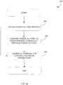
- the method 200 comprises obtaining at step 202 a current reading of power outtake on the power system 206 of Fig. 2 . Once the reading is obtained, the latter may be compared at step 204 to a predetermined threshold to evaluate whether the current power outtake is within predefined limits or to a previous power outtake reading obtained at step 202 to identify a trend, i.e. increase or decrease, in the power outtake.
- a command may be generated at step 206 to control at least one aircraft engine parameter, such as an acceleration reference signal, fuel flow, variable geometry position, load shedding, according to the current power outtake. Alternatively, the command may be generated directly from the power outtake reading without comparison.
- the command generation step 206 illustratively comprises an engine performance and stability optimization step 208 and an engine power extraction control step 210.
- the power extraction control step 210 may be used to generate a command for the purpose of relaxing or increasing the power outtake levels allowed to the aircraft loads as well as controlling the amount of power extracted from the gas turbine engine 10 to adjust the acceleration capability of the engine 10 or recover from unpredicted events, as discussed above with reference to the system 100 of Figure 2 .
- the engine performance and stability optimization step 208 illustratively comprises at least one of a control transient capability step 212, a control fuel consumption step 214, a control power delivery step 216, and a monitor engine condition step 218.
- the control transient capability step 212 may involve generating a command for optimizing the transient capability of the engine 10 according to the power outtake reading. For instance, and as discussed above with reference to the system 100 of Figure 2 , the control transient capability step 212 may involve generating a command for adjusting the engine's acceleration reference signal or adjusting the position of the engine's variable geometries in real-time to optimize engine performance and achieve optimal power capability.
- the control fuel consumption step 214 may involve generating a command for adjusting in real-time the amount of fuel flowing through the engine 10 in reaction to a change in power outtake.
- the issued command may also enhance the stability of the engine 10, for example by controlling the throttle setting.
- the monitor engine condition step 218 may involve using the power outtake reading obtained at step 202 to more accurately monitor the condition of the engine 10, for example to enhance the reliability of power assurance checks or temperature estimates.
Landscapes
- Engineering & Computer Science (AREA)
- Chemical & Material Sciences (AREA)
- Combustion & Propulsion (AREA)
- Mechanical Engineering (AREA)
- General Engineering & Computer Science (AREA)
- Physics & Mathematics (AREA)
- Aviation & Aerospace Engineering (AREA)
- Fluid Mechanics (AREA)
- Geometry (AREA)
- Health & Medical Sciences (AREA)
- Artificial Intelligence (AREA)
- Computer Vision & Pattern Recognition (AREA)
- Evolutionary Computation (AREA)
- Medical Informatics (AREA)
- Software Systems (AREA)
- General Physics & Mathematics (AREA)
- Automation & Control Theory (AREA)
- Control Of Turbines (AREA)
- Output Control And Ontrol Of Special Type Engine (AREA)
Claims (14)
- System (102) zur Steuerung eines Gasturbinenmotors (10) zur Flugzeugleistungsversorgung, wobei das System Folgendes umfasst:eine Empfangseinheit (112), die dazu konfiguriert ist, ein Messsignal zu empfangen, das einen Messwert des Leistungsausgangs, der derzeit durch mindestens eine an den Motor gekoppelte Last (108) verbraucht wird, umfasst; undeine Verarbeitungseinheit, die dazu konfiguriert ist:den Messwert aus dem Messsignal zu extrahieren; undeine Beschleunigungsfähigkeit des Motors auf Grundlage zumindest des extrahierten Messwerts zu bestimmen,dadurch gekennzeichnet, dass die Verarbeitungseinheit ferner dazu konfiguriert ist:zu bestimmen, ob, wenn zusätzliche Beschleunigung benötigt wird, der Leistungsausgang erhöht werden kann;wenn der Leistungsausgang erhöht werden kann, ein Steuersignal als Befehl zum Verstärken des Beschleunigungsablaufs des Motors zu erzeugen, um einen zugelassenen Leistungsausgang dynamisch zu erhöhen;wenn der Leistungsausgang nicht erhöht werden kann, das Steuersignal als Lastabwurfbefehl zum Steigern der Beschleunigungsfähigkeit zu erzeugen und das Steuersignal an den Motor (10) zu senden, um zumindest eine der mindestens einen an den Motor gekoppelten Last selektiv abzutrennen oder den Beschleunigungsablauf zu modifizieren.
- System nach Anspruch 1, wobei die Verarbeitungseinheit dazu konfiguriert ist, den extrahierten Messwert mit einem vorher festgelegten Schwellenwert zu vergleichen und das Steuersignal auf Grundlage des Vergleichs zu erzeugen.
- System nach Anspruch 2, wobei die Verarbeitungseinheit dazu konfiguriert ist, eine Reaktion des Motors auf eine Veränderung des durch die mindestens eine Last (108) verbrauchten Leistungsausgangs, der anhand des Vergleichs bestimmt wurde, vorherzusagen und das Steuersignal gemäß der vorhergesagten Reaktion zu erzeugen.
- System nach einem der Ansprüche 1 bis 3, wobei die Verarbeitungseinheit dazu konfiguriert ist, ein zweites Steuersignal als mindestens ein Leistungssteuersignal zum Modifizieren einer Menge der durch die mindestens eine Last (108) verbrauchten Leistung zu erzeugen.
- System nach Anspruch 4, wobei die Verarbeitungseinheit dazu konfiguriert ist, das zweite Steuersignal als Befehl zum Einstellen einer Position mindestens einer variablen Geometrie des Motors in Richtung einer Position, die mindestens eines von einem Zykluswirkungsgrad des Motors und einer Leistungsfähigkeit des Pumpgrenzenabstands des Motors optimiert, zu erzeugen.
- System nach Anspruch 4 oder 5, wobei die Verarbeitungseinheit dazu konfiguriert ist, das zweite Steuersignal als Befehl zum Einstellen eines Kraftstoffstroms durch den Motor zu erzeugen.
- System nach einem der Ansprüche 1 bis 6, wobei die Verarbeitungseinheit dazu konfiguriert ist, den Messwert des derzeit durch die mindestens eine Last verbrauchten Leistungsausgangs beim Durchführen von zumindest einer von einer Leistungssicherungsprüfungsberechnung und einer Turbinentemperaturberechnung zu verwenden.
- Verfahren zur Steuerung eines Gasturbinenmotors (10) zur Flugzeugleistungsversorgung, der ein System nach Anspruch 1 umfasst, wobei das Verfahren Folgendes umfasst:Empfangen eines Messsignals, das einen Messwert eines Leistungsausgangs, der derzeit durch mindestens eine an den Motor (10) gekoppelte Last (108) verbraucht wird, umfasst;Extrahieren des Messwerts aus dem Messsignal; undBestimmen einer Beschleunigungsfähigkeit des Motors (10) auf Grundlage des extrahierten Messwerts,dadurch gekennzeichnet, dass es ferner Folgendes umfasst:Bestimmen, ob, wenn zusätzliche Beschleunigung benötigt wird, der Leistungsausgang erhöht werden kann;wenn der Leistungsausgang erhöht werden kann, Erzeugen eines Steuersignals als Befehl zum Verstärken des Beschleunigungsablaufs des Motors, um einen zugelassenen Leistungsausgang dynamisch zu erhöhen;wenn der Leistungsausgang nicht erhöht werden kann, Erzeugen des Steuersignals als Lastabwurfbefehl zum Steigern der Beschleunigungsfähigkeit undSenden des Steuersignals an den Motor (10), um zumindest eine der mindestens einen an den Motor gekoppelten Last selektiv abzutrennen oder den Beschleunigungsablauf zu modifizieren.
- Verfahren nach Anspruch 8, ferner umfassend das Vergleichen des extrahierten Messwerts mit einem vorher festgelegten Schwellenwert und das Erzeugen des Steuersignals auf Grundlage des Vergleichs.
- Verfahren nach Anspruch 9, ferner umfassend das Vorhersagen einer Reaktion des Motors (10) auf eine Veränderung des durch die mindestens eine Last (108) verbrauchten Leistungsausgangs, der anhand des Vergleichs bestimmt wird, und wobei das Erzeugen des Steuersignals das Erzeugen des Steuersignals gemäß der vorhergesagten Reaktion umfasst.
- Verfahren nach einem der Ansprüche 8 bis 10, wobei das Erzeugen des Steuersignals das Erzeugen eines zweiten Steuersignals als mindestens ein Leistungssteuersignal zum Modifizieren einer Menge der durch die mindestens eine Last (108) verbrauchten Leistung.
- Verfahren nach Anspruch 11, wobei das Erzeugen des Steuersignals das Erzeugen des zweiten Steuersignals als Befehl zum Einstellen einer Position mindestens einer variablen Geometrie des Motors (10) in Richtung einer Position, die mindestens eines von einem Zykluswirkungsgrad des Motors und einer Leistungsfähigkeit des Pumpgrenzenabstands des Motors optimiert, umfasst.
- Verfahren nach Anspruch 11 oder 12, wobei das Erzeugen des Steuersignals das Erzeugen des zweiten Steuersignals als Befehl zum Einstellen eines Kraftstoffstroms durch den Motor (10) umfasst.
- Verfahren nach einem der Ansprüche 8 bis 13, ferner umfassend das Verwenden des Messwerts des derzeit durch die mindestens eine Last (108) verbrauchten Leistungsausgangs beim Durchführen mindestens einer von einer Leistungssicherheitsprüfungsberechnung und einer Turbinentemperaturberechnung.
Applications Claiming Priority (1)
| Application Number | Priority Date | Filing Date | Title |
|---|---|---|---|
| US201261670785P | 2012-07-12 | 2012-07-12 |
Publications (3)
| Publication Number | Publication Date |
|---|---|
| EP2685068A2 EP2685068A2 (de) | 2014-01-15 |
| EP2685068A3 EP2685068A3 (de) | 2017-01-11 |
| EP2685068B1 true EP2685068B1 (de) | 2018-05-02 |
Family
ID=48793875
Family Applications (1)
| Application Number | Title | Priority Date | Filing Date |
|---|---|---|---|
| EP13173975.7A Active EP2685068B1 (de) | 2012-07-12 | 2013-06-27 | Steuerungssystem und Verfahren zur steuerung einer Gasturbine zur Flugzeugleistungsversorgung |
Country Status (3)
| Country | Link |
|---|---|
| US (2) | US9382010B2 (de) |
| EP (1) | EP2685068B1 (de) |
| CA (2) | CA2804462C (de) |
Families Citing this family (34)
| Publication number | Priority date | Publication date | Assignee | Title |
|---|---|---|---|---|
| CA2804462C (en) | 2012-07-12 | 2021-05-25 | Pratt & Whitney Canada Corp. | Aircraft power outtake management |
| FR3004701B1 (fr) * | 2013-04-22 | 2015-04-03 | Snecma | Dispositif de delestage des alternateurs d'un turboreacteur pendant ses accelerations |
| FR3007787B1 (fr) * | 2013-06-27 | 2015-06-26 | Eurocopter France | Procede et dispositif de protection dun moteur de giravion en survitesse |
| US9944400B2 (en) | 2014-02-11 | 2018-04-17 | Sikorsky Aircraft Corporation | Adaptive engine acceleration for accessory loads |
| US10850863B2 (en) * | 2014-03-04 | 2020-12-01 | Pratt & Whitney Canada Corp. | System and method for operating a multi-engine aircraft in an auxiliary power unit mode |
| US9979337B2 (en) * | 2014-04-24 | 2018-05-22 | Generac Power Systems, Inc. | Method of loadshedding for a variable speed, constant frequency generator |
| EP2945244B1 (de) * | 2014-05-15 | 2022-07-06 | Airbus Operations GmbH | Leistungs- und Datenverteilungsmodul und Verfahren zur Leistungs- und Datenverteilung in einem Flugkörper |
| US10196923B2 (en) | 2014-08-28 | 2019-02-05 | Pratt & Whitney Canada Corp. | Operation of aircraft engines during transient conditions |
| US10144527B2 (en) | 2015-03-25 | 2018-12-04 | Skyfront Corp. | Flight controller with generator control |
| GB201515279D0 (en) * | 2015-08-28 | 2015-10-14 | Rolls Royce Plc | Propulsion system |
| US10883424B2 (en) | 2016-07-19 | 2021-01-05 | Pratt & Whitney Canada Corp. | Multi-spool gas turbine engine architecture |
| US11415063B2 (en) | 2016-09-15 | 2022-08-16 | Pratt & Whitney Canada Corp. | Reverse-flow gas turbine engine |
| US10584646B2 (en) * | 2016-07-29 | 2020-03-10 | Pratt & Whitney Canada Corp. | System and method for control of gas turbine engine |
| US11035293B2 (en) | 2016-09-15 | 2021-06-15 | Pratt & Whitney Canada Corp. | Reverse flow gas turbine engine with offset RGB |
| US10465611B2 (en) | 2016-09-15 | 2019-11-05 | Pratt & Whitney Canada Corp. | Reverse flow multi-spool gas turbine engine with aft-end accessory gearbox drivingly connected to both high pressure spool and low pressure spool |
| US10815899B2 (en) | 2016-11-15 | 2020-10-27 | Pratt & Whitney Canada Corp. | Gas turbine engine accessories arrangement |
| FR3059734A1 (fr) | 2016-12-06 | 2018-06-08 | Airbus Operations Gmbh | Procede et dispositif de controle des prelevements sur une turbomachine limitant le risque de pompage par echange d'informations entre un gestionnaire d'energie et un systeme de controle de la turbomachine |
| US10808624B2 (en) | 2017-02-09 | 2020-10-20 | Pratt & Whitney Canada Corp. | Turbine rotor with low over-speed requirements |
| US10746188B2 (en) | 2017-03-14 | 2020-08-18 | Pratt & Whitney Canada Corp. | Inter-shaft bearing connected to a compressor boost system |
| US11008111B2 (en) * | 2017-06-26 | 2021-05-18 | General Electric Company | Propulsion system for an aircraft |
| US11139992B1 (en) * | 2017-10-30 | 2021-10-05 | Rockwell Collins, Inc. | Systems and methods for remotely powered data concentrators for distributed IMA system |
| US11528165B2 (en) * | 2018-01-19 | 2022-12-13 | Textron Innovations, Inc. | Remote sensor data acquisition |
| US11085321B2 (en) | 2018-01-30 | 2021-08-10 | Honeywell International Inc. | Bleed air compensated continuous power assurance analysis system and method |
| US10822996B2 (en) * | 2018-03-12 | 2020-11-03 | General Electric Company | Gas turbine engine health determination |
| US11536153B2 (en) | 2018-08-08 | 2022-12-27 | Pratt & Whitney Canada Corp. | Turboshaft gas turbine engine |
| WO2020093264A1 (zh) * | 2018-11-07 | 2020-05-14 | 大连理工大学 | 一种航空发动机过渡态控制规律优化的设计方法 |
| US12241426B2 (en) * | 2019-01-03 | 2025-03-04 | General Electric Company | Systems and methods of controlling load share and speed of engines in multiple-engine propulsion systems |
| CN109782584B (zh) * | 2019-01-21 | 2022-05-17 | 杭州澎康自动化科技有限公司 | 一种抽背型汽轮机自整定控制方法 |
| US11591075B2 (en) | 2019-06-13 | 2023-02-28 | Hamilton Sundstrand Corporation | Intelligent engine offload of auxiliary loads for enhanced engine durability |
| US11346290B2 (en) | 2020-02-21 | 2022-05-31 | Raytheon Technologies Corporation | Speed limiting for power turbine governing and protection in a turboshaft engine |
| US20220097864A1 (en) * | 2020-09-30 | 2022-03-31 | Ge Avio S.R.L. | Aircraft performance optimization based on engine performance monitoring |
| US11773782B2 (en) * | 2020-12-23 | 2023-10-03 | Rtx Corporation | Gas turbine engines having cryogenic fuel systems |
| FR3129377B1 (fr) * | 2021-11-25 | 2023-11-24 | Safran | Fourniture d’energie dans un aeronef utilisant un contrôle de statisme |
| CN117818949B (zh) * | 2023-05-05 | 2026-03-13 | 无锡沃研科技有限公司 | 一种自适应定量计量控制方法 |
Family Cites Families (30)
| Publication number | Priority date | Publication date | Assignee | Title |
|---|---|---|---|---|
| US4687946A (en) | 1972-04-26 | 1987-08-18 | Westinghouse Electric Corp. | System and method for operating a steam turbine with digital computer control and with improved monitoring |
| US4529887A (en) * | 1983-06-20 | 1985-07-16 | General Electric Company | Rapid power response turbine |
| AU2002220089A1 (en) | 2000-11-14 | 2002-05-27 | Capstone Turbine Corporation | Method and apparatus for turbogenerator anti-surge control |
| US6820429B2 (en) * | 2001-11-15 | 2004-11-23 | Goodrich Pump & Engine Control Systems, Inc. | Adaptive acceleration schedules for gas turbine engine control systems |
| US6931856B2 (en) | 2003-09-12 | 2005-08-23 | Mes International, Inc. | Multi-spool turbogenerator system and control method |
| US7975465B2 (en) * | 2003-10-27 | 2011-07-12 | United Technologies Corporation | Hybrid engine accessory power system |
| US7814491B1 (en) | 2004-04-14 | 2010-10-12 | Oracle America, Inc. | Method and apparatus for managing system resources using a container model |
| US7254465B2 (en) * | 2004-06-04 | 2007-08-07 | Honeywell International, Inc. | No-break-power-transfer control system for variable frequency electrical power systems |
| US20060174629A1 (en) * | 2004-08-24 | 2006-08-10 | Honeywell International, Inc | Method and system for coordinating engine operation with electrical power extraction in a more electric vehicle |
| US7285871B2 (en) * | 2004-08-25 | 2007-10-23 | Honeywell International, Inc. | Engine power extraction control system |
| JP2006274868A (ja) * | 2005-03-29 | 2006-10-12 | Honda Motor Co Ltd | ガスタービン発電機の運転制御装置 |
| GB2435529B (en) | 2006-02-23 | 2008-06-18 | Rolls Royce Plc | A generator control arrangement |
| US8209101B2 (en) | 2006-08-29 | 2012-06-26 | The Boeing Company | Method and system for adaptive power management |
| FR2909233B1 (fr) | 2006-11-23 | 2011-03-04 | Hispano Suiza Sa | Alimentation d'un aeronef en energie electrique |
| US7615881B2 (en) | 2006-12-20 | 2009-11-10 | Hamilton Sundstrand Corporation | Power turbine speed control using electrical load following |
| US8098054B2 (en) | 2007-10-10 | 2012-01-17 | John Alexander Verschuur | Optimal load controller method and device |
| US8237308B2 (en) * | 2007-12-12 | 2012-08-07 | The Boeing Company | Dynamic electrical load management |
| US7795825B2 (en) | 2008-09-15 | 2010-09-14 | Caterpillar Inc | Over-voltage and under-voltage management for electric drive system |
| US7969038B2 (en) | 2008-12-12 | 2011-06-28 | Honeywell International Inc. | Power regeneration management system |
| US8099227B2 (en) * | 2009-03-19 | 2012-01-17 | Pratt & Whitney Canada Corp. | Control of gas turbine engine |
| US8295995B2 (en) | 2009-04-22 | 2012-10-23 | Hamilton Sundstrand Corporation | Distributed approach to electronic engine control for gas turbine engines |
| US8078342B2 (en) * | 2009-05-01 | 2011-12-13 | Honeywell International Inc. | Method for active power management and allocation of functionality |
| GB0912340D0 (en) * | 2009-07-16 | 2009-08-26 | Rolls Royce Plc | Aircraft power management system |
| GB0915616D0 (en) | 2009-09-08 | 2009-10-07 | Rolls Royce Plc | Surge margin regulation |
| JP5356967B2 (ja) * | 2009-09-29 | 2013-12-04 | 本田技研工業株式会社 | 航空機用ガスタービン・エンジン |
| FR2952130B1 (fr) | 2009-10-30 | 2018-09-07 | Safran Electrical & Power | Demarreur-generateur de turbomachine et procede pour sa commande. |
| US8489246B2 (en) | 2010-02-26 | 2013-07-16 | Pratt & Whitney Canada Corp. | Hybrid control system |
| FR2968716B1 (fr) | 2010-12-13 | 2012-12-28 | Turbomeca | Procede de controle de la generation electrique appliquee a une turbine a gaz d'aeronef et turbomoteur mettant en oeuvre un tel procede |
| FR2972711B1 (fr) | 2011-03-17 | 2013-04-19 | Hispano Suiza Sa | Alimentation en energie electrique d'un aeronef |
| CA2804462C (en) | 2012-07-12 | 2021-05-25 | Pratt & Whitney Canada Corp. | Aircraft power outtake management |
-
2013
- 2013-01-29 CA CA2804462A patent/CA2804462C/en active Active
- 2013-01-29 CA CA3114227A patent/CA3114227C/en active Active
- 2013-01-29 US US13/753,158 patent/US9382010B2/en active Active
- 2013-06-27 EP EP13173975.7A patent/EP2685068B1/de active Active
-
2016
- 2016-06-07 US US15/175,467 patent/US10280788B2/en active Active
Non-Patent Citations (1)
| Title |
|---|
| None * |
Also Published As
| Publication number | Publication date |
|---|---|
| CA3114227A1 (en) | 2014-01-12 |
| US9382010B2 (en) | 2016-07-05 |
| CA2804462C (en) | 2021-05-25 |
| EP2685068A3 (de) | 2017-01-11 |
| US10280788B2 (en) | 2019-05-07 |
| US20160281529A1 (en) | 2016-09-29 |
| EP2685068A2 (de) | 2014-01-15 |
| CA3114227C (en) | 2023-09-19 |
| CA2804462A1 (en) | 2014-01-12 |
| US20140297155A1 (en) | 2014-10-02 |
Similar Documents
| Publication | Publication Date | Title |
|---|---|---|
| US10280788B2 (en) | Aircraft power outtake management | |
| CA2896470C (en) | Engine health monitoring and power allocation control for a turbine engine using electric generators | |
| US10965231B2 (en) | Lifing and performance optimization limit management for turbine engine | |
| CN110844088B (zh) | 用于飞行器的容错性混合电动推进系统 | |
| US9346553B2 (en) | Balancing the power of two turboshaft engines of an aircraft | |
| JP5923515B2 (ja) | 航空機ガスタービンに使用される発電制御方法および該方法を実施する装置 | |
| EP2356327B1 (de) | Adaptives system mit integrierter sicherheit für fadec-gesteuerte gasturbinentriebwerke | |
| EP1990506B1 (de) | Betrieb eines Flugzeugmotors nach Not-Abschaltung | |
| US9841038B2 (en) | Controlling method and system for compressed air supply to a pneumatic network, in particular in an aircraft | |
| US9303566B2 (en) | Method for optimizing the control of a free turbine power package for an aircraft, and control for implementing same | |
| US12291344B2 (en) | Aircraft performance optimization based on engine performance monitoring | |
| EP2762707B1 (de) | Verfahren zur Steuerung eines Kühlsystems | |
| KR101444383B1 (ko) | 터빈 엔진의 조절 장치 및 방법과 항공기 | |
| US10677251B2 (en) | Method and device for testing samples on a turbine engine minimizing the risk of surge by the exchange of information between an energy manager and a system for testing the turbine engine | |
| EP4368500B1 (de) | Systeme und verfahren zur steuerung des fluiddrucks einer propellersteuereinheit |
Legal Events
| Date | Code | Title | Description |
|---|---|---|---|
| PUAI | Public reference made under article 153(3) epc to a published international application that has entered the european phase |
Free format text: ORIGINAL CODE: 0009012 |
|
| AK | Designated contracting states |
Kind code of ref document: A2 Designated state(s): AL AT BE BG CH CY CZ DE DK EE ES FI FR GB GR HR HU IE IS IT LI LT LU LV MC MK MT NL NO PL PT RO RS SE SI SK SM TR |
|
| AX | Request for extension of the european patent |
Extension state: BA ME |
|
| PUAL | Search report despatched |
Free format text: ORIGINAL CODE: 0009013 |
|
| AK | Designated contracting states |
Kind code of ref document: A3 Designated state(s): AL AT BE BG CH CY CZ DE DK EE ES FI FR GB GR HR HU IE IS IT LI LT LU LV MC MK MT NL NO PL PT RO RS SE SI SK SM TR |
|
| AX | Request for extension of the european patent |
Extension state: BA ME |
|
| RIC1 | Information provided on ipc code assigned before grant |
Ipc: F02C 9/54 20060101ALI20161208BHEP Ipc: F01D 21/00 20060101ALI20161208BHEP Ipc: F02C 7/042 20060101ALI20161208BHEP Ipc: F02C 9/26 20060101ALI20161208BHEP Ipc: F02C 9/28 20060101AFI20161208BHEP Ipc: G05B 13/02 20060101ALI20161208BHEP Ipc: B64D 31/06 20060101ALI20161208BHEP |
|
| STAA | Information on the status of an ep patent application or granted ep patent |
Free format text: STATUS: REQUEST FOR EXAMINATION WAS MADE |
|
| 17P | Request for examination filed |
Effective date: 20170711 |
|
| RBV | Designated contracting states (corrected) |
Designated state(s): AL AT BE BG CH CY CZ DE DK EE ES FI FR GB GR HR HU IE IS IT LI LT LU LV MC MK MT NL NO PL PT RO RS SE SI SK SM TR |
|
| RIC1 | Information provided on ipc code assigned before grant |
Ipc: F02C 7/042 20060101ALI20171018BHEP Ipc: F02C 9/28 20060101AFI20171018BHEP Ipc: G05B 13/02 20060101ALI20171018BHEP Ipc: F01D 21/00 20060101ALI20171018BHEP Ipc: F02C 9/54 20060101ALI20171018BHEP Ipc: F02C 9/26 20060101ALI20171018BHEP Ipc: B64D 31/06 20060101ALI20171018BHEP |
|
| GRAP | Despatch of communication of intention to grant a patent |
Free format text: ORIGINAL CODE: EPIDOSNIGR1 |
|
| STAA | Information on the status of an ep patent application or granted ep patent |
Free format text: STATUS: GRANT OF PATENT IS INTENDED |
|
| INTG | Intention to grant announced |
Effective date: 20171124 |
|
| GRAS | Grant fee paid |
Free format text: ORIGINAL CODE: EPIDOSNIGR3 |
|
| GRAA | (expected) grant |
Free format text: ORIGINAL CODE: 0009210 |
|
| STAA | Information on the status of an ep patent application or granted ep patent |
Free format text: STATUS: THE PATENT HAS BEEN GRANTED |
|
| AK | Designated contracting states |
Kind code of ref document: B1 Designated state(s): AL AT BE BG CH CY CZ DE DK EE ES FI FR GB GR HR HU IE IS IT LI LT LU LV MC MK MT NL NO PL PT RO RS SE SI SK SM TR |
|
| REG | Reference to a national code |
Ref country code: GB Ref legal event code: FG4D |
|
| REG | Reference to a national code |
Ref country code: CH Ref legal event code: EP Ref country code: AT Ref legal event code: REF Ref document number: 995509 Country of ref document: AT Kind code of ref document: T Effective date: 20180515 |
|
| REG | Reference to a national code |
Ref country code: DE Ref legal event code: R096 Ref document number: 602013036788 Country of ref document: DE Ref country code: IE Ref legal event code: FG4D |
|
| REG | Reference to a national code |
Ref country code: FR Ref legal event code: PLFP Year of fee payment: 6 |
|
| REG | Reference to a national code |
Ref country code: NL Ref legal event code: MP Effective date: 20180502 |
|
| REG | Reference to a national code |
Ref country code: LT Ref legal event code: MG4D |
|
| PG25 | Lapsed in a contracting state [announced via postgrant information from national office to epo] |
Ref country code: SE Free format text: LAPSE BECAUSE OF FAILURE TO SUBMIT A TRANSLATION OF THE DESCRIPTION OR TO PAY THE FEE WITHIN THE PRESCRIBED TIME-LIMIT Effective date: 20180502 Ref country code: FI Free format text: LAPSE BECAUSE OF FAILURE TO SUBMIT A TRANSLATION OF THE DESCRIPTION OR TO PAY THE FEE WITHIN THE PRESCRIBED TIME-LIMIT Effective date: 20180502 Ref country code: BG Free format text: LAPSE BECAUSE OF FAILURE TO SUBMIT A TRANSLATION OF THE DESCRIPTION OR TO PAY THE FEE WITHIN THE PRESCRIBED TIME-LIMIT Effective date: 20180802 Ref country code: NO Free format text: LAPSE BECAUSE OF FAILURE TO SUBMIT A TRANSLATION OF THE DESCRIPTION OR TO PAY THE FEE WITHIN THE PRESCRIBED TIME-LIMIT Effective date: 20180802 Ref country code: LT Free format text: LAPSE BECAUSE OF FAILURE TO SUBMIT A TRANSLATION OF THE DESCRIPTION OR TO PAY THE FEE WITHIN THE PRESCRIBED TIME-LIMIT Effective date: 20180502 Ref country code: ES Free format text: LAPSE BECAUSE OF FAILURE TO SUBMIT A TRANSLATION OF THE DESCRIPTION OR TO PAY THE FEE WITHIN THE PRESCRIBED TIME-LIMIT Effective date: 20180502 |
|
| PG25 | Lapsed in a contracting state [announced via postgrant information from national office to epo] |
Ref country code: GR Free format text: LAPSE BECAUSE OF FAILURE TO SUBMIT A TRANSLATION OF THE DESCRIPTION OR TO PAY THE FEE WITHIN THE PRESCRIBED TIME-LIMIT Effective date: 20180803 Ref country code: HR Free format text: LAPSE BECAUSE OF FAILURE TO SUBMIT A TRANSLATION OF THE DESCRIPTION OR TO PAY THE FEE WITHIN THE PRESCRIBED TIME-LIMIT Effective date: 20180502 Ref country code: LV Free format text: LAPSE BECAUSE OF FAILURE TO SUBMIT A TRANSLATION OF THE DESCRIPTION OR TO PAY THE FEE WITHIN THE PRESCRIBED TIME-LIMIT Effective date: 20180502 Ref country code: NL Free format text: LAPSE BECAUSE OF FAILURE TO SUBMIT A TRANSLATION OF THE DESCRIPTION OR TO PAY THE FEE WITHIN THE PRESCRIBED TIME-LIMIT Effective date: 20180502 Ref country code: RS Free format text: LAPSE BECAUSE OF FAILURE TO SUBMIT A TRANSLATION OF THE DESCRIPTION OR TO PAY THE FEE WITHIN THE PRESCRIBED TIME-LIMIT Effective date: 20180502 |
|
| REG | Reference to a national code |
Ref country code: AT Ref legal event code: MK05 Ref document number: 995509 Country of ref document: AT Kind code of ref document: T Effective date: 20180502 |
|
| PG25 | Lapsed in a contracting state [announced via postgrant information from national office to epo] |
Ref country code: AT Free format text: LAPSE BECAUSE OF FAILURE TO SUBMIT A TRANSLATION OF THE DESCRIPTION OR TO PAY THE FEE WITHIN THE PRESCRIBED TIME-LIMIT Effective date: 20180502 Ref country code: CZ Free format text: LAPSE BECAUSE OF FAILURE TO SUBMIT A TRANSLATION OF THE DESCRIPTION OR TO PAY THE FEE WITHIN THE PRESCRIBED TIME-LIMIT Effective date: 20180502 Ref country code: RO Free format text: LAPSE BECAUSE OF FAILURE TO SUBMIT A TRANSLATION OF THE DESCRIPTION OR TO PAY THE FEE WITHIN THE PRESCRIBED TIME-LIMIT Effective date: 20180502 Ref country code: EE Free format text: LAPSE BECAUSE OF FAILURE TO SUBMIT A TRANSLATION OF THE DESCRIPTION OR TO PAY THE FEE WITHIN THE PRESCRIBED TIME-LIMIT Effective date: 20180502 Ref country code: PL Free format text: LAPSE BECAUSE OF FAILURE TO SUBMIT A TRANSLATION OF THE DESCRIPTION OR TO PAY THE FEE WITHIN THE PRESCRIBED TIME-LIMIT Effective date: 20180502 Ref country code: DK Free format text: LAPSE BECAUSE OF FAILURE TO SUBMIT A TRANSLATION OF THE DESCRIPTION OR TO PAY THE FEE WITHIN THE PRESCRIBED TIME-LIMIT Effective date: 20180502 Ref country code: SK Free format text: LAPSE BECAUSE OF FAILURE TO SUBMIT A TRANSLATION OF THE DESCRIPTION OR TO PAY THE FEE WITHIN THE PRESCRIBED TIME-LIMIT Effective date: 20180502 |
|
| REG | Reference to a national code |
Ref country code: CH Ref legal event code: PL |
|
| REG | Reference to a national code |
Ref country code: DE Ref legal event code: R097 Ref document number: 602013036788 Country of ref document: DE |
|
| PG25 | Lapsed in a contracting state [announced via postgrant information from national office to epo] |
Ref country code: IT Free format text: LAPSE BECAUSE OF FAILURE TO SUBMIT A TRANSLATION OF THE DESCRIPTION OR TO PAY THE FEE WITHIN THE PRESCRIBED TIME-LIMIT Effective date: 20180502 Ref country code: SM Free format text: LAPSE BECAUSE OF FAILURE TO SUBMIT A TRANSLATION OF THE DESCRIPTION OR TO PAY THE FEE WITHIN THE PRESCRIBED TIME-LIMIT Effective date: 20180502 |
|
| REG | Reference to a national code |
Ref country code: BE Ref legal event code: MM Effective date: 20180630 |
|
| PLBE | No opposition filed within time limit |
Free format text: ORIGINAL CODE: 0009261 |
|
| STAA | Information on the status of an ep patent application or granted ep patent |
Free format text: STATUS: NO OPPOSITION FILED WITHIN TIME LIMIT |
|
| PG25 | Lapsed in a contracting state [announced via postgrant information from national office to epo] |
Ref country code: MC Free format text: LAPSE BECAUSE OF FAILURE TO SUBMIT A TRANSLATION OF THE DESCRIPTION OR TO PAY THE FEE WITHIN THE PRESCRIBED TIME-LIMIT Effective date: 20180502 Ref country code: LU Free format text: LAPSE BECAUSE OF NON-PAYMENT OF DUE FEES Effective date: 20180627 |
|
| REG | Reference to a national code |
Ref country code: IE Ref legal event code: MM4A |
|
| 26N | No opposition filed |
Effective date: 20190205 |
|
| PG25 | Lapsed in a contracting state [announced via postgrant information from national office to epo] |
Ref country code: CH Free format text: LAPSE BECAUSE OF NON-PAYMENT OF DUE FEES Effective date: 20180630 Ref country code: LI Free format text: LAPSE BECAUSE OF NON-PAYMENT OF DUE FEES Effective date: 20180630 Ref country code: IE Free format text: LAPSE BECAUSE OF NON-PAYMENT OF DUE FEES Effective date: 20180627 |
|
| PG25 | Lapsed in a contracting state [announced via postgrant information from national office to epo] |
Ref country code: SI Free format text: LAPSE BECAUSE OF FAILURE TO SUBMIT A TRANSLATION OF THE DESCRIPTION OR TO PAY THE FEE WITHIN THE PRESCRIBED TIME-LIMIT Effective date: 20180502 Ref country code: BE Free format text: LAPSE BECAUSE OF NON-PAYMENT OF DUE FEES Effective date: 20180630 |
|
| PG25 | Lapsed in a contracting state [announced via postgrant information from national office to epo] |
Ref country code: AL Free format text: LAPSE BECAUSE OF FAILURE TO SUBMIT A TRANSLATION OF THE DESCRIPTION OR TO PAY THE FEE WITHIN THE PRESCRIBED TIME-LIMIT Effective date: 20180502 |
|
| PG25 | Lapsed in a contracting state [announced via postgrant information from national office to epo] |
Ref country code: MT Free format text: LAPSE BECAUSE OF NON-PAYMENT OF DUE FEES Effective date: 20180627 |
|
| PG25 | Lapsed in a contracting state [announced via postgrant information from national office to epo] |
Ref country code: TR Free format text: LAPSE BECAUSE OF FAILURE TO SUBMIT A TRANSLATION OF THE DESCRIPTION OR TO PAY THE FEE WITHIN THE PRESCRIBED TIME-LIMIT Effective date: 20180502 |
|
| PG25 | Lapsed in a contracting state [announced via postgrant information from national office to epo] |
Ref country code: HU Free format text: LAPSE BECAUSE OF FAILURE TO SUBMIT A TRANSLATION OF THE DESCRIPTION OR TO PAY THE FEE WITHIN THE PRESCRIBED TIME-LIMIT; INVALID AB INITIO Effective date: 20130627 Ref country code: PT Free format text: LAPSE BECAUSE OF FAILURE TO SUBMIT A TRANSLATION OF THE DESCRIPTION OR TO PAY THE FEE WITHIN THE PRESCRIBED TIME-LIMIT Effective date: 20180502 |
|
| PG25 | Lapsed in a contracting state [announced via postgrant information from national office to epo] |
Ref country code: MK Free format text: LAPSE BECAUSE OF NON-PAYMENT OF DUE FEES Effective date: 20180502 Ref country code: CY Free format text: LAPSE BECAUSE OF FAILURE TO SUBMIT A TRANSLATION OF THE DESCRIPTION OR TO PAY THE FEE WITHIN THE PRESCRIBED TIME-LIMIT Effective date: 20180502 |
|
| PG25 | Lapsed in a contracting state [announced via postgrant information from national office to epo] |
Ref country code: IS Free format text: LAPSE BECAUSE OF FAILURE TO SUBMIT A TRANSLATION OF THE DESCRIPTION OR TO PAY THE FEE WITHIN THE PRESCRIBED TIME-LIMIT Effective date: 20180902 |
|
| P01 | Opt-out of the competence of the unified patent court (upc) registered |
Effective date: 20230530 |
|
| PGFP | Annual fee paid to national office [announced via postgrant information from national office to epo] |
Ref country code: DE Payment date: 20250520 Year of fee payment: 13 |
|
| PGFP | Annual fee paid to national office [announced via postgrant information from national office to epo] |
Ref country code: GB Payment date: 20250520 Year of fee payment: 13 |
|
| PGFP | Annual fee paid to national office [announced via postgrant information from national office to epo] |
Ref country code: FR Payment date: 20250520 Year of fee payment: 13 |