EP2685046A1 - Crown-shaped separation device for separating oil and water in well - Google Patents
Crown-shaped separation device for separating oil and water in well Download PDFInfo
- Publication number
- EP2685046A1 EP2685046A1 EP11860600.3A EP11860600A EP2685046A1 EP 2685046 A1 EP2685046 A1 EP 2685046A1 EP 11860600 A EP11860600 A EP 11860600A EP 2685046 A1 EP2685046 A1 EP 2685046A1
- Authority
- EP
- European Patent Office
- Prior art keywords
- central tube
- cup
- separator
- crown
- sedimentation
- Prior art date
- Legal status (The legal status is an assumption and is not a legal conclusion. Google has not performed a legal analysis and makes no representation as to the accuracy of the status listed.)
- Granted
Links
Images


Classifications
-
- E—FIXED CONSTRUCTIONS
- E21—EARTH OR ROCK DRILLING; MINING
- E21B—EARTH OR ROCK DRILLING; OBTAINING OIL, GAS, WATER, SOLUBLE OR MELTABLE MATERIALS OR A SLURRY OF MINERALS FROM WELLS
- E21B43/00—Methods or apparatus for obtaining oil, gas, water, soluble or meltable materials or a slurry of minerals from wells
- E21B43/34—Arrangements for separating materials produced by the well
- E21B43/38—Arrangements for separating materials produced by the well in the well
-
- B—PERFORMING OPERATIONS; TRANSPORTING
- B01—PHYSICAL OR CHEMICAL PROCESSES OR APPARATUS IN GENERAL
- B01D—SEPARATION
- B01D17/00—Separation of liquids, not provided for elsewhere, e.g. by thermal diffusion
- B01D17/02—Separation of non-miscible liquids
- B01D17/0208—Separation of non-miscible liquids by sedimentation
Definitions
- the invention relates to a downhole separating device for separating oil and water, particularly a downhole Crown-shaped separating device for separating oil and water.
- the conventional oil well lifting equipment of the oil field draws three-phase mixture of gas, oil and water during the downhole operation, and a small amount of which carry part of oil layer sand along with swabbing fluid.
- water and sand contained in the swabbing fluid increase. If water content is too high during the production of oil well, the production cost will increase; if oil layer sand enters into the oil pump along with the fluid, the probability of stuck pump is greatly increased, which may result in unnecessary downhole servicing operation. Therefore, the prior separator used in the oil field can not effectively separate oil and water underground.
- the object of invention is to solve the problem that the prior separator used in the oil field can not effectively separate oil and water when the downhole fluid is drawn by the pumping unit, and to provide a dwonhole crown-shaped separating device for separating oil and water.
- a downhole crown-shaped separating device for separating oil and water in accordance with the present invention, the separating device comprising a oil pump joint, a coupling collar, a tube joint, a central tube and a well-washing valve which are fixedly connected with one another from top to bottom in sequence.
- the crown-shaped separating device further comprises N sections of separators sleeved on the central tube, and N+1 separator joints sleeved on the central tube sequentially from top to bottom, N being the natural number, one section of the separator being provided between two adjacent separator joints.
- Each section of separator includes an upper locating sleeve, a lower locating sleeve, a plurality of sedimentation cups sleeved on the central tube sequentially from top to bottom, in which the two neighboring sedimentation cups are nested into each other and form a gap between them, the uppermost sedimentation cup on each section of separator being fixedly connected to the central tube by the upper locating sleeve, and the lowermost sedimentation cup on each section of separator being fixedly connected to the central tube by the lower locating sleeve, and a plurality of ribbed separating bowls, each sedimentation cup being provided with the ribbed separating bowl embedded therein.
- the sedimentation cup is crown-shaped and has a multi-ribbed polygon bottom, the rib of which forms an pitch angle of 30 to 60 degrees with the horizontal line, and the middle part of the sedimentation cup is a hollow cylinder, the upper edge of the sedimentation cup being zigzag-shaped which corresponds to the shape of the bottom, the sedimentation cup having a cup holder for holding said sedimentation cup which forms an annular space with the central tube.
- a group of intake holes are provided on the central tube corresponding to the annular space, a bar-shaped gap is opened on the cup holder of the sedimentation cup, the ribbed separating bowl has same shape as that of the bottom of the sedimentation cup, the ribbed separating bowl is provided with several liquid passages, and the outer diameter of the sedimentation cup is smaller than that of the separator joint.
- N stands for the natural number.
- the separator 6 divides the extracted fluid into several parts, and aggregate and lift the oil rapidly by means of the pitch angle formed between the rib of the bottom 10-1 of the sedimentation cup 10 and the horizontal line; the shape of the ribbed separating bowl 11 in the separator 6 is consistent with the shape of the bottom 10-1 of the sedimentation cup, and the ribbed separating bowl 11 is provided with several liquid passages 11-1, so that the fluid entered into the separator 6 aggregated and lifted again, which ensures the effective separation of oil and water in the separator.
- the device according to the present invention realizes the separation of oil and water in fluid when the viscosity of the underground fluid is greater than 2mPa.s, reduces the water cut of the fluid swabbed by the oil pump, and increases oil-production efficiency.
- the downhole crown-shaped separating device for separating oil and water in accordance with the present embodiment comprises an oil pump joint 1, a coupling collar 2, a tube joint 3, a central tube 4 and a well-flushing valve5 which are fixedly connected with one another from top to bottom in sequence.
- the crown-shaped separating device further comprises N sections of separators 6 sleeved on the central tube, and N+1 separator joints 7 sleeved on the central tube sequentially from top to bottom, N being the natural number.
- One section of the separator 6 is provided between two adjacent separator joints 7.
- Each section of separator 6 includes an upper locating sleeve 8, a lower locating sleeve 9, a plurality of sedimentation cups 10 and a plurality of ribbed separating bowls 11.
- the plurality of sedimentation cups 10 are sleeved on the central tube 4 sequentially from top to bottom, in which the two neighboring sedimentation cups are nested into each other and form a gap between them.
- the uppermost sedimentation cup 10 on each section of separator is fixedly connected to the central tube 4 by the upper locating sleeve 8, and the lowermost sedimentation cup 10 on each section of separator 6 is fixedly connected to the central tube 4 by the lower locating sleeve 9, each sedimentation cup being provided with the ribbed separating bowl 11 embedded therein.
- the sedimentation cup is crown-shaped and has a multi-ribbed polygon bottom 10-1.
- the rib 10-1-1 of the bottom 10-1 forms an pitch angle ⁇ of 30 to 60 degrees with the horizontal line
- the middle part of the sedimentation cup 10 is a hollow cylinder, the upper edge of the sedimentation cup 10 being zigzag-shaped which corresponds to the shape of the bottom 10-1.
- the sedimentation cup 10 has a cup holder 10-2 for holding said sedimentation cup which forms an annular space with the central tube 4.
- a group of intake holes 12 are provided on the central tube 4 corresponding to the annular space.
- a bar-shaped gap 10-2-1 is opened on the cup holder 10-2 of the sedimentation cup 10.
- the ribbed separating bowl 11 has the same shape as that of the bottom 10-1 of the sedimentation cup 10, and the ribbed separating bowl 11 is provided with several liquid passages 11-1.
- the outer diameter of the sedimentation cup 10 is smaller than that of the separator joint 7. N stands for the natural number.
- Example 2 the present embodiment is described with reference to figure 1 .
- the number of the separator 6 of the embodiment is 60-80.
- the separating effect is good.
- Other constitution and connection relationship is the same as that of example 1.
- Example 3 the present embodiment is described with reference to figure 3 .
- the number of each group of intake holes 12 on the central tube 4 corresponding to the annular space of the embodiment is 3-12.
- the separating effect is good.
- Other constitution and connection relationship is the same as that of example 1 or example 2.
- Example 4 the present embodiment is described with reference to figure 3 .
- the aperture of the intake hole 12 on the central tube 4 corresponding to the annular space of the embodiment is 0.9mm-1.2mm.
- the separating effect is good.
- Other constitution and connection relationship is the same as that of example 1, example 2 or example 3.
- Example 5 the present embodiment is described with reference to figure 2 .
- the upper locating sleeve 8 and the central tube 4 are fixedly connected by bolts, and the lower locating sleeve 9 and the central tube 4 are fixedly connected by bolts.
- the structure is stable.
- Other constitution and connection relationship is the same as that of example 1, example 2, example 3 or example 4.
- the oil pump joint 1 is connected with the oil pump; the mixture of oil and water passes through the lowest separator firstly; the separator 6 divides the extracted fluid into several parts, and aggregates and lift the oil rapidly by means of the pitch angle formed between the rib of the bottom 10-1 of the sedimentation cup 10 and the horizontal line.
- the shape of the ribbed separating bowl 11 in the separator 6 is consistent with the shape of the bottom 10-1 of the sedimentation cup 10, and the ribbed separating bowl 11 is provided with several liquid passages 11-1, so that the fluid entered into the separator 6 is aggregated and lifted again.
- the oil is further aggregated and lifted to a separator 6 by means of density difference of oil and water. Water then passes into the central tube 8 through the intake holes 12 and are extracted by the oil pump and pressurized and then injected into the objective interval.
Landscapes
- Geology (AREA)
- Life Sciences & Earth Sciences (AREA)
- Engineering & Computer Science (AREA)
- Mining & Mineral Resources (AREA)
- Physics & Mathematics (AREA)
- Environmental & Geological Engineering (AREA)
- Fluid Mechanics (AREA)
- General Life Sciences & Earth Sciences (AREA)
- Geochemistry & Mineralogy (AREA)
- Thermal Sciences (AREA)
- Chemical & Material Sciences (AREA)
- Chemical Kinetics & Catalysis (AREA)
- Removal Of Floating Material (AREA)
Abstract
Description
- The invention relates to a downhole separating device for separating oil and water, particularly a downhole Crown-shaped separating device for separating oil and water.
- The conventional oil well lifting equipment of the oil field draws three-phase mixture of gas, oil and water during the downhole operation, and a small amount of which carry part of oil layer sand along with swabbing fluid. With lengthening of the development time of multiply formation field, water and sand contained in the swabbing fluid increase. If water content is too high during the production of oil well, the production cost will increase; if oil layer sand enters into the oil pump along with the fluid, the probability of stuck pump is greatly increased, which may result in unnecessary downhole servicing operation. Therefore, the prior separator used in the oil field can not effectively separate oil and water underground.
- The object of invention is to solve the problem that the prior separator used in the oil field can not effectively separate oil and water when the downhole fluid is drawn by the pumping unit, and to provide a dwonhole crown-shaped separating device for separating oil and water.
- The technical solution of the present invention is as follows: there is provided a downhole crown-shaped separating device for separating oil and water in accordance with the present invention, the separating device comprising a oil pump joint, a coupling collar, a tube joint, a central tube and a well-washing valve which are fixedly connected with one another from top to bottom in sequence. The crown-shaped separating device further comprises N sections of separators sleeved on the central tube, and N+1 separator joints sleeved on the central tube sequentially from top to bottom, N being the natural number, one section of the separator being provided between two adjacent separator joints. Each section of separator includes an upper locating sleeve, a lower locating sleeve, a plurality of sedimentation cups sleeved on the central tube sequentially from top to bottom, in which the two neighboring sedimentation cups are nested into each other and form a gap between them, the uppermost sedimentation cup on each section of separator being fixedly connected to the central tube by the upper locating sleeve, and the lowermost sedimentation cup on each section of separator being fixedly connected to the central tube by the lower locating sleeve, and a plurality of ribbed separating bowls, each sedimentation cup being provided with the ribbed separating bowl embedded therein. The sedimentation cup is crown-shaped and has a multi-ribbed polygon bottom, the rib of which forms an pitch angle of 30 to 60 degrees with the horizontal line, and the middle part of the sedimentation cup is a hollow cylinder, the upper edge of the sedimentation cup being zigzag-shaped which corresponds to the shape of the bottom, the sedimentation cup having a cup holder for holding said sedimentation cup which forms an annular space with the central tube. A group of intake holes are provided on the central tube corresponding to the annular space, a bar-shaped gap is opened on the cup holder of the sedimentation cup, the ribbed separating bowl has same shape as that of the bottom of the sedimentation cup, the ribbed separating bowl is provided with several liquid passages, and the outer diameter of the sedimentation cup is smaller than that of the separator joint. N stands for the natural number.
- This invention has following advantages compared with the prior art: the
separator 6 divides the extracted fluid into several parts, and aggregate and lift the oil rapidly by means of the pitch angle formed between the rib of the bottom 10-1 of thesedimentation cup 10 and the horizontal line; the shape of the ribbed separatingbowl 11 in theseparator 6 is consistent with the shape of the bottom 10-1 of the sedimentation cup, and the ribbed separatingbowl 11 is provided with several liquid passages 11-1, so that the fluid entered into theseparator 6 aggregated and lifted again, which ensures the effective separation of oil and water in the separator. The device according to the present invention realizes the separation of oil and water in fluid when the viscosity of the underground fluid is greater than 2mPa.s, reduces the water cut of the fluid swabbed by the oil pump, and increases oil-production efficiency. -
-
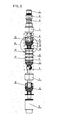
Figure 1 is the front view of the overall structure of the separating device in accordance with the present invention; -
Figure 2 is a partial cross-sectional view of the overall structure of the separating device in accordance with the present invention; -
Figure 3 is an enlarged view of A shown in theFigure 2 ; -
Figure 4 is a diagram showing the positional relation of two neighboringsedimentation cups 10 and the ribbed separatingbowl 11; -
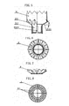
Figure 5 is a front view of thesedimentation cup 10 in accordance with the present invention; -
Figure 6 is a top view of thesedimentation cup 10 in accordance with the present invention; -
Figure 7 is a front view of the ribbed separatingbowl 11 in accordance with the present invention; -
Figure 8 is a top view of the ribbed separatingbowl 11 in accordance with the present invention. - Example 1: the present embodiment is now described with reference to
Figures 1-8 . The downhole crown-shaped separating device for separating oil and water in accordance with the present embodiment comprises anoil pump joint 1, acoupling collar 2, atube joint 3, acentral tube 4 and a well-flushing valve5 which are fixedly connected with one another from top to bottom in sequence. The crown-shaped separating device further comprises N sections ofseparators 6 sleeved on the central tube, and N+1separator joints 7 sleeved on the central tube sequentially from top to bottom, N being the natural number. One section of theseparator 6 is provided between twoadjacent separator joints 7. Each section ofseparator 6 includes an upper locatingsleeve 8, a lower locatingsleeve 9, a plurality ofsedimentation cups 10 and a plurality of ribbed separatingbowls 11. The plurality ofsedimentation cups 10 are sleeved on thecentral tube 4 sequentially from top to bottom, in which the two neighboring sedimentation cups are nested into each other and form a gap between them. Theuppermost sedimentation cup 10 on each section of separator is fixedly connected to thecentral tube 4 by the upper locatingsleeve 8, and thelowermost sedimentation cup 10 on each section ofseparator 6 is fixedly connected to thecentral tube 4 by the lower locatingsleeve 9, each sedimentation cup being provided with the ribbed separatingbowl 11 embedded therein. The sedimentation cup is crown-shaped and has a multi-ribbed polygon bottom 10-1. The rib 10-1-1 of the bottom 10-1 forms an pitch angle α of 30 to 60 degrees with the horizontal line, and the middle part of thesedimentation cup 10 is a hollow cylinder, the upper edge of thesedimentation cup 10 being zigzag-shaped which corresponds to the shape of the bottom 10-1. Thesedimentation cup 10 has a cup holder 10-2 for holding said sedimentation cup which forms an annular space with thecentral tube 4. A group ofintake holes 12 are provided on thecentral tube 4 corresponding to the annular space. A bar-shaped gap 10-2-1 is opened on the cup holder 10-2 of thesedimentation cup 10. The ribbed separatingbowl 11 has the same shape as that of the bottom 10-1 of thesedimentation cup 10, and the ribbed separatingbowl 11 is provided with several liquid passages 11-1. The outer diameter of thesedimentation cup 10 is smaller than that of theseparator joint 7. N stands for the natural number. - Example 2: the present embodiment is described with reference to
figure 1 . The number of theseparator 6 of the embodiment is 60-80. The separating effect is good. Other constitution and connection relationship is the same as that of example 1. - Example 3: the present embodiment is described with reference to
figure 3 . The number of each group ofintake holes 12 on thecentral tube 4 corresponding to the annular space of the embodiment is 3-12. The separating effect is good. Other constitution and connection relationship is the same as that of example 1 or example 2. - Example 4: the present embodiment is described with reference to
figure 3 . The aperture of theintake hole 12 on thecentral tube 4 corresponding to the annular space of the embodiment is 0.9mm-1.2mm. The separating effect is good. Other constitution and connection relationship is the same as that of example 1, example 2 or example 3. - Example 5: the present embodiment is described with reference to
figure 2 . The upper locatingsleeve 8 and thecentral tube 4 are fixedly connected by bolts, and the lower locatingsleeve 9 and thecentral tube 4 are fixedly connected by bolts. The structure is stable. Other constitution and connection relationship is the same as that of example 1, example 2, example 3 or example 4. - The working process of the downhole crown-shaped separating device for separating underground oil and water according to the present invention: the
oil pump joint 1 is connected with the oil pump; the mixture of oil and water passes through the lowest separator firstly; theseparator 6 divides the extracted fluid into several parts, and aggregates and lift the oil rapidly by means of the pitch angle formed between the rib of the bottom 10-1 of thesedimentation cup 10 and the horizontal line. The shape of the ribbed separatingbowl 11 in theseparator 6 is consistent with the shape of the bottom 10-1 of thesedimentation cup 10, and the ribbed separatingbowl 11 is provided with several liquid passages 11-1, so that the fluid entered into theseparator 6 is aggregated and lifted again. The oil is further aggregated and lifted to aseparator 6 by means of density difference of oil and water. Water then passes into thecentral tube 8 through theintake holes 12 and are extracted by the oil pump and pressurized and then injected into the objective interval.
Claims (5)
- A downhole crown-shaped separating device for separating oil and water, comprising a oil pump joint (1), a coupling collar (2), a tube joint (3), a central tube (4) and a well-flushing valve (5) which are fixedly connected with one another from top to bottom in sequence;
wherein the crown-shaped separating device further comprises N sections of separators (6) sleeved on the central tube (4), and N+1 separator joints (7) sleeved on the central tube (4) sequentially from top to bottom, N being the natural number, one section of the separator (6) being provided between two adjacent separator joints (7),
wherein each section of separator (6) includes
an upper locating sleeve (8),
a lower locating sleeve (9),
a plurality of sedimentation cups (10) sleeved on the central tube (4) sequentially from top to bottom, in which the two neighboring sedimentation cups (10) are nested into each other and form a gap between them, the uppermost sedimentation cup (10) on each section of separator (6) being fixedly connected to the central tube (4) by the upper locating sleeve (8), and the lowermost sedimentation cup (10) on each section of separator (6) being fixedly connected to the central tube (4) by the lower locating sleeve (9), and
a plurality of ribbed separating bowls (11), each sedimentation cup (10) being provided with the ribbed separating bowl (11) embedded therein,
wherein the sedimentation cup (10) is crown-shaped and has a multi-ribbed polygon bottom (10-1), the rib (10-1-1) of which forms an pitch angle (α) of 30 to 60 degrees with the horizontal line, and the middle part of the sedimentation cup (10) is a hollow cylinder, the upper edge of the sedimentation cup (10) being zigzag-shaped which corresponds to the shape of the bottom (10-1), the sedimentation cup (10) having a cup holder (10-2) for holding said sedimentation cup which forms an annular space with the central tube (4), and
wherein a group of intake holes (12) are provided on the central tube (4) corresponding to the annular space, a bar-shaped gap (10-2-1) is opened on the cup holder (10-2) of the sedimentation cup (10), the ribbed separating bowl (11) has same shape as that of the bottom (10-1) of the sedimentation cup (10), the ribbed separating bowl (11) is provided with several liquid passages (11-1), and the outer diameter of the sedimentation cup (10) is smaller than that of the separator joint (7). N stands for the natural number. - The downhole crown-shaped separating device according to claim 1, characterized in that the number of the separator (6) is 60 to 80.
- The downhole crown-shaped separating device according to claim 1 or 2, characterized in that the number of each group of intake holes (12) on the central tube (4) corresponding to the annular space is 3 to 12.
- The downhole crown-shaped separating device according to claim 3, characterized in that the aperture of the intake hole (12) on the central tube (4) corresponding to the annular space is 0.9mm to 1.2mm.
- The downhole crown-shaped separating device according to claim 1, 2 or 4, characterized in that the upper locating sleeve (8) and the central tube (4) are fixedly connected together by bolts, and the lower locating sleeve (9) and the central tube (4) are fixedly connected by bolts.
Applications Claiming Priority (3)
| Application Number | Priority Date | Filing Date | Title |
|---|---|---|---|
| CN2011200601749U CN201943683U (en) | 2011-03-09 | 2011-03-09 | Crown-shaped separating device for realizing separation of underground oil and water |
| CN2011200601753U CN201943684U (en) | 2011-03-09 | 2011-03-09 | Crown-shaped gas anchor capable of realizing underground gas-liquid separation |
| PCT/CN2011/001640 WO2012119283A1 (en) | 2011-03-09 | 2011-09-28 | Crown-shaped separation device for separating oil and water in well |
Publications (4)
| Publication Number | Publication Date |
|---|---|
| EP2685046A1 true EP2685046A1 (en) | 2014-01-15 |
| EP2685046A4 EP2685046A4 (en) | 2014-10-08 |
| EP2685046B1 EP2685046B1 (en) | 2016-12-21 |
| EP2685046B8 EP2685046B8 (en) | 2017-04-05 |
Family
ID=46797393
Family Applications (1)
| Application Number | Title | Priority Date | Filing Date |
|---|---|---|---|
| EP11860600.3A Active EP2685046B8 (en) | 2011-03-09 | 2011-09-28 | Crown-shaped separation device for separating oil and water in well |
Country Status (4)
| Country | Link |
|---|---|
| US (1) | US8757257B2 (en) |
| EP (1) | EP2685046B8 (en) |
| CA (1) | CA2828993C (en) |
| WO (1) | WO2012119283A1 (en) |
Families Citing this family (4)
| Publication number | Priority date | Publication date | Assignee | Title |
|---|---|---|---|---|
| CN106801599A (en) | 2017-02-03 | 2017-06-06 | 中国石油天然气股份有限公司 | Downhole Oil-Gas-Water-Sand Separation Method and Separator |
| CN108854163A (en) * | 2018-07-10 | 2018-11-23 | 中国石油天然气股份有限公司 | An oil-water separation device and separation method for gravity separation of lipophilic packing |
| RU200894U1 (en) * | 2019-12-27 | 2020-11-17 | Александр Васильевич Николаев | CENTRIFUGAL-GRAVITATION GAS-SESSION FILTER |
| CN120487012B (en) * | 2025-06-17 | 2026-06-26 | 中海油田服务股份有限公司 | An internal labyrinth-type sand control, water control, and oil stabilization device |
Family Cites Families (10)
| Publication number | Priority date | Publication date | Assignee | Title |
|---|---|---|---|---|
| US3931011A (en) * | 1973-11-19 | 1976-01-06 | Racor Industries, Inc. | Fluid separation apparatus |
| US4241788A (en) * | 1979-01-31 | 1980-12-30 | Armco Inc. | Multiple cup downwell gas separator |
| RU2269649C2 (en) * | 2002-06-04 | 2006-02-10 | Закрытое акционерное общество "РА-Кубаньнефтемаш" | Bottom hole separator |
| CN100532782C (en) * | 2003-12-08 | 2009-08-26 | 大庆油田有限责任公司第一采油厂 | Oil well downhole gas-liquid separation method and multiple settling cup isoflow gas anchor |
| CN101025080B (en) * | 2006-12-26 | 2011-05-11 | 大庆油田有限责任公司 | Method for realizing high-water containing same-well injection-production by multi-cup equi-flow type down-hole oil-water separator |
| CN101377126B (en) | 2007-08-28 | 2013-04-17 | 大庆油田有限责任公司 | Corrugation-shaped sedimentation cup and multiple-cup equal flow type gas anchor |
| CN201599019U (en) * | 2009-12-11 | 2010-10-06 | 大庆石油管理局 | Settlement cup of producing well |
| CN101773742B (en) * | 2010-02-21 | 2011-09-28 | 大庆油田有限责任公司 | Multilayer uniform-flow-type coalescence oil-water separator and separation method |
| CN201943683U (en) * | 2011-03-09 | 2011-08-24 | 大庆油田有限责任公司 | Crown-shaped separating device for realizing separation of underground oil and water |
| CN201943684U (en) * | 2011-03-09 | 2011-08-24 | 大庆油田有限责任公司 | Crown-shaped gas anchor capable of realizing underground gas-liquid separation |
-
2011
- 2011-09-28 CA CA2828993A patent/CA2828993C/en active Active
- 2011-09-28 WO PCT/CN2011/001640 patent/WO2012119283A1/en not_active Ceased
- 2011-09-28 EP EP11860600.3A patent/EP2685046B8/en active Active
-
2013
- 2013-09-09 US US14/020,942 patent/US8757257B2/en active Active
Also Published As
| Publication number | Publication date |
|---|---|
| US20140000872A1 (en) | 2014-01-02 |
| EP2685046A4 (en) | 2014-10-08 |
| EP2685046B1 (en) | 2016-12-21 |
| WO2012119283A1 (en) | 2012-09-13 |
| CA2828993C (en) | 2017-03-07 |
| CA2828993A1 (en) | 2012-09-13 |
| EP2685046B8 (en) | 2017-04-05 |
| US8757257B2 (en) | 2014-06-24 |
Similar Documents
| Publication | Publication Date | Title |
|---|---|---|
| CN101377126B (en) | Corrugation-shaped sedimentation cup and multiple-cup equal flow type gas anchor | |
| CA2828993C (en) | A downhole crown-shaped separating device for separating oil and water | |
| CN201943683U (en) | Crown-shaped separating device for realizing separation of underground oil and water | |
| CN115232637B (en) | Vertical crude oil dehydration equipment | |
| CN207111067U (en) | Tandem type quantifies shear force separation gas anchor and the combination of multi-stage quantization gas anchor | |
| RU2335658C2 (en) | Electrohydraulic method of oil production and method to this effect | |
| CN200996291Y (en) | Oil-vapour separater under well | |
| CN203362134U (en) | Sand-preventing gas-preventing desilting device | |
| CN102102507B (en) | Double-cavity sand and gas anchor | |
| CN103939319B (en) | Three-tube type linear dynamo oil pump | |
| CN202970674U (en) | Degassing, silt removing and liquid separating device at wellhead | |
| CN201943684U (en) | Crown-shaped gas anchor capable of realizing underground gas-liquid separation | |
| CN201068792Y (en) | Corrugated settling cup and multi-cup iso-flow rate anchor | |
| CN204627948U (en) | Oil well deep pump | |
| CN201696020U (en) | High-efficiency exhaust anchor | |
| CN201599019U (en) | Settlement cup of producing well | |
| CN204476387U (en) | The oil gas sand separator of efficient energy-saving | |
| CN103071321A (en) | Downhole Liquid Sand Multistage Separator | |
| CN203214038U (en) | Long-acting degassing sand-prevention device suitable for 7-inch casing pipe production well | |
| CN202431258U (en) | Flow string for oil well | |
| CN111005711A (en) | Oil well underground oil-gas separation device and method | |
| CN201627574U (en) | High-efficient gas-sand anchor | |
| CN104912495A (en) | Drill pipe air operated slip capable of clearing impurities | |
| CN218794089U (en) | Sand and scale sedimentation cyclone separation device | |
| CN204082117U (en) | A kind of new-type waterpower swab |
Legal Events
| Date | Code | Title | Description |
|---|---|---|---|
| PUAI | Public reference made under article 153(3) epc to a published international application that has entered the european phase |
Free format text: ORIGINAL CODE: 0009012 |
|
| 17P | Request for examination filed |
Effective date: 20130917 |
|
| AK | Designated contracting states |
Kind code of ref document: A1 Designated state(s): AL AT BE BG CH CY CZ DE DK EE ES FI FR GB GR HR HU IE IS IT LI LT LU LV MC MK MT NL NO PL PT RO RS SE SI SK SM TR |
|
| DAX | Request for extension of the european patent (deleted) | ||
| RAP3 | Party data changed (applicant data changed or rights of an application transferred) |
Owner name: DAQING OILFIELD CO. LIT Owner name: PETROCHINA COMPANY LIMITED |
|
| A4 | Supplementary search report drawn up and despatched |
Effective date: 20140908 |
|
| RIC1 | Information provided on ipc code assigned before grant |
Ipc: B01D 17/02 20060101ALI20140902BHEP Ipc: E21B 43/38 20060101AFI20140902BHEP Ipc: B01D 45/02 20060101ALI20140902BHEP |
|
| RIC1 | Information provided on ipc code assigned before grant |
Ipc: B01D 45/02 20060101ALI20160614BHEP Ipc: B01D 17/02 20060101ALI20160614BHEP Ipc: E21B 43/38 20060101AFI20160614BHEP |
|
| GRAP | Despatch of communication of intention to grant a patent |
Free format text: ORIGINAL CODE: EPIDOSNIGR1 |
|
| INTG | Intention to grant announced |
Effective date: 20160803 |
|
| GRAS | Grant fee paid |
Free format text: ORIGINAL CODE: EPIDOSNIGR3 |
|
| GRAA | (expected) grant |
Free format text: ORIGINAL CODE: 0009210 |
|
| AK | Designated contracting states |
Kind code of ref document: B1 Designated state(s): AL AT BE BG CH CY CZ DE DK EE ES FI FR GB GR HR HU IE IS IT LI LT LU LV MC MK MT NL NO PL PT RO RS SE SI SK SM TR |
|
| REG | Reference to a national code |
Ref country code: GB Ref legal event code: FG4D |
|
| REG | Reference to a national code |
Ref country code: CH Ref legal event code: EP |
|
| REG | Reference to a national code |
Ref country code: IE Ref legal event code: FG4D |
|
| REG | Reference to a national code |
Ref country code: AT Ref legal event code: REF Ref document number: 855686 Country of ref document: AT Kind code of ref document: T Effective date: 20170115 |
|
| REG | Reference to a national code |
Ref country code: DE Ref legal event code: R096 Ref document number: 602011033735 Country of ref document: DE |
|
| RAP2 | Party data changed (patent owner data changed or rights of a patent transferred) |
Owner name: PETROCHINA COMPANY LIMITED Owner name: DAQING OILFIELD CO. LTD. |
|
| PG25 | Lapsed in a contracting state [announced via postgrant information from national office to epo] |
Ref country code: LV Free format text: LAPSE BECAUSE OF FAILURE TO SUBMIT A TRANSLATION OF THE DESCRIPTION OR TO PAY THE FEE WITHIN THE PRESCRIBED TIME-LIMIT Effective date: 20161221 |
|
| REG | Reference to a national code |
Ref country code: LT Ref legal event code: MG4D |
|
| REG | Reference to a national code |
Ref country code: NL Ref legal event code: MP Effective date: 20161221 |
|
| PG25 | Lapsed in a contracting state [announced via postgrant information from national office to epo] |
Ref country code: LT Free format text: LAPSE BECAUSE OF FAILURE TO SUBMIT A TRANSLATION OF THE DESCRIPTION OR TO PAY THE FEE WITHIN THE PRESCRIBED TIME-LIMIT Effective date: 20161221 Ref country code: GR Free format text: LAPSE BECAUSE OF FAILURE TO SUBMIT A TRANSLATION OF THE DESCRIPTION OR TO PAY THE FEE WITHIN THE PRESCRIBED TIME-LIMIT Effective date: 20170322 Ref country code: SE Free format text: LAPSE BECAUSE OF FAILURE TO SUBMIT A TRANSLATION OF THE DESCRIPTION OR TO PAY THE FEE WITHIN THE PRESCRIBED TIME-LIMIT Effective date: 20161221 |
|
| REG | Reference to a national code |
Ref country code: NO Ref legal event code: T2 Effective date: 20161221 |
|
| REG | Reference to a national code |
Ref country code: AT Ref legal event code: MK05 Ref document number: 855686 Country of ref document: AT Kind code of ref document: T Effective date: 20161221 |
|
| PG25 | Lapsed in a contracting state [announced via postgrant information from national office to epo] |
Ref country code: RS Free format text: LAPSE BECAUSE OF FAILURE TO SUBMIT A TRANSLATION OF THE DESCRIPTION OR TO PAY THE FEE WITHIN THE PRESCRIBED TIME-LIMIT Effective date: 20161221 Ref country code: HR Free format text: LAPSE BECAUSE OF FAILURE TO SUBMIT A TRANSLATION OF THE DESCRIPTION OR TO PAY THE FEE WITHIN THE PRESCRIBED TIME-LIMIT Effective date: 20161221 Ref country code: FI Free format text: LAPSE BECAUSE OF FAILURE TO SUBMIT A TRANSLATION OF THE DESCRIPTION OR TO PAY THE FEE WITHIN THE PRESCRIBED TIME-LIMIT Effective date: 20161221 |
|
| PG25 | Lapsed in a contracting state [announced via postgrant information from national office to epo] |
Ref country code: NL Free format text: LAPSE BECAUSE OF FAILURE TO SUBMIT A TRANSLATION OF THE DESCRIPTION OR TO PAY THE FEE WITHIN THE PRESCRIBED TIME-LIMIT Effective date: 20161221 |
|
| PG25 | Lapsed in a contracting state [announced via postgrant information from national office to epo] |
Ref country code: EE Free format text: LAPSE BECAUSE OF FAILURE TO SUBMIT A TRANSLATION OF THE DESCRIPTION OR TO PAY THE FEE WITHIN THE PRESCRIBED TIME-LIMIT Effective date: 20161221 Ref country code: IS Free format text: LAPSE BECAUSE OF FAILURE TO SUBMIT A TRANSLATION OF THE DESCRIPTION OR TO PAY THE FEE WITHIN THE PRESCRIBED TIME-LIMIT Effective date: 20170421 Ref country code: SK Free format text: LAPSE BECAUSE OF FAILURE TO SUBMIT A TRANSLATION OF THE DESCRIPTION OR TO PAY THE FEE WITHIN THE PRESCRIBED TIME-LIMIT Effective date: 20161221 Ref country code: CZ Free format text: LAPSE BECAUSE OF FAILURE TO SUBMIT A TRANSLATION OF THE DESCRIPTION OR TO PAY THE FEE WITHIN THE PRESCRIBED TIME-LIMIT Effective date: 20161221 Ref country code: RO Free format text: LAPSE BECAUSE OF FAILURE TO SUBMIT A TRANSLATION OF THE DESCRIPTION OR TO PAY THE FEE WITHIN THE PRESCRIBED TIME-LIMIT Effective date: 20161221 |
|
| PG25 | Lapsed in a contracting state [announced via postgrant information from national office to epo] |
Ref country code: IT Free format text: LAPSE BECAUSE OF FAILURE TO SUBMIT A TRANSLATION OF THE DESCRIPTION OR TO PAY THE FEE WITHIN THE PRESCRIBED TIME-LIMIT Effective date: 20161221 Ref country code: PT Free format text: LAPSE BECAUSE OF FAILURE TO SUBMIT A TRANSLATION OF THE DESCRIPTION OR TO PAY THE FEE WITHIN THE PRESCRIBED TIME-LIMIT Effective date: 20170421 Ref country code: PL Free format text: LAPSE BECAUSE OF FAILURE TO SUBMIT A TRANSLATION OF THE DESCRIPTION OR TO PAY THE FEE WITHIN THE PRESCRIBED TIME-LIMIT Effective date: 20161221 Ref country code: SM Free format text: LAPSE BECAUSE OF FAILURE TO SUBMIT A TRANSLATION OF THE DESCRIPTION OR TO PAY THE FEE WITHIN THE PRESCRIBED TIME-LIMIT Effective date: 20161221 Ref country code: ES Free format text: LAPSE BECAUSE OF FAILURE TO SUBMIT A TRANSLATION OF THE DESCRIPTION OR TO PAY THE FEE WITHIN THE PRESCRIBED TIME-LIMIT Effective date: 20161221 Ref country code: BG Free format text: LAPSE BECAUSE OF FAILURE TO SUBMIT A TRANSLATION OF THE DESCRIPTION OR TO PAY THE FEE WITHIN THE PRESCRIBED TIME-LIMIT Effective date: 20170321 Ref country code: AT Free format text: LAPSE BECAUSE OF FAILURE TO SUBMIT A TRANSLATION OF THE DESCRIPTION OR TO PAY THE FEE WITHIN THE PRESCRIBED TIME-LIMIT Effective date: 20161221 Ref country code: BE Free format text: LAPSE BECAUSE OF FAILURE TO SUBMIT A TRANSLATION OF THE DESCRIPTION OR TO PAY THE FEE WITHIN THE PRESCRIBED TIME-LIMIT Effective date: 20161221 |
|
| REG | Reference to a national code |
Ref country code: DE Ref legal event code: R097 Ref document number: 602011033735 Country of ref document: DE |
|
| PLBE | No opposition filed within time limit |
Free format text: ORIGINAL CODE: 0009261 |
|
| STAA | Information on the status of an ep patent application or granted ep patent |
Free format text: STATUS: NO OPPOSITION FILED WITHIN TIME LIMIT |
|
| 26N | No opposition filed |
Effective date: 20170922 |
|
| PG25 | Lapsed in a contracting state [announced via postgrant information from national office to epo] |
Ref country code: DK Free format text: LAPSE BECAUSE OF FAILURE TO SUBMIT A TRANSLATION OF THE DESCRIPTION OR TO PAY THE FEE WITHIN THE PRESCRIBED TIME-LIMIT Effective date: 20161221 |
|
| PG25 | Lapsed in a contracting state [announced via postgrant information from national office to epo] |
Ref country code: SI Free format text: LAPSE BECAUSE OF FAILURE TO SUBMIT A TRANSLATION OF THE DESCRIPTION OR TO PAY THE FEE WITHIN THE PRESCRIBED TIME-LIMIT Effective date: 20161221 |
|
| REG | Reference to a national code |
Ref country code: DE Ref legal event code: R119 Ref document number: 602011033735 Country of ref document: DE |
|
| REG | Reference to a national code |
Ref country code: CH Ref legal event code: PL |
|
| PG25 | Lapsed in a contracting state [announced via postgrant information from national office to epo] |
Ref country code: MC Free format text: LAPSE BECAUSE OF FAILURE TO SUBMIT A TRANSLATION OF THE DESCRIPTION OR TO PAY THE FEE WITHIN THE PRESCRIBED TIME-LIMIT Effective date: 20161221 |
|
| REG | Reference to a national code |
Ref country code: IE Ref legal event code: MM4A |
|
| PG25 | Lapsed in a contracting state [announced via postgrant information from national office to epo] |
Ref country code: LU Free format text: LAPSE BECAUSE OF NON-PAYMENT OF DUE FEES Effective date: 20170928 |
|
| REG | Reference to a national code |
Ref country code: FR Ref legal event code: ST Effective date: 20180531 |
|
| PG25 | Lapsed in a contracting state [announced via postgrant information from national office to epo] |
Ref country code: LI Free format text: LAPSE BECAUSE OF NON-PAYMENT OF DUE FEES Effective date: 20170930 Ref country code: DE Free format text: LAPSE BECAUSE OF NON-PAYMENT OF DUE FEES Effective date: 20180404 Ref country code: IE Free format text: LAPSE BECAUSE OF NON-PAYMENT OF DUE FEES Effective date: 20170928 Ref country code: CH Free format text: LAPSE BECAUSE OF NON-PAYMENT OF DUE FEES Effective date: 20170930 |
|
| PG25 | Lapsed in a contracting state [announced via postgrant information from national office to epo] |
Ref country code: FR Free format text: LAPSE BECAUSE OF NON-PAYMENT OF DUE FEES Effective date: 20171002 |
|
| PG25 | Lapsed in a contracting state [announced via postgrant information from national office to epo] |
Ref country code: MT Free format text: LAPSE BECAUSE OF NON-PAYMENT OF DUE FEES Effective date: 20170928 |
|
| PG25 | Lapsed in a contracting state [announced via postgrant information from national office to epo] |
Ref country code: HU Free format text: LAPSE BECAUSE OF FAILURE TO SUBMIT A TRANSLATION OF THE DESCRIPTION OR TO PAY THE FEE WITHIN THE PRESCRIBED TIME-LIMIT; INVALID AB INITIO Effective date: 20110928 |
|
| PG25 | Lapsed in a contracting state [announced via postgrant information from national office to epo] |
Ref country code: CY Free format text: LAPSE BECAUSE OF NON-PAYMENT OF DUE FEES Effective date: 20161221 |
|
| PG25 | Lapsed in a contracting state [announced via postgrant information from national office to epo] |
Ref country code: MK Free format text: LAPSE BECAUSE OF FAILURE TO SUBMIT A TRANSLATION OF THE DESCRIPTION OR TO PAY THE FEE WITHIN THE PRESCRIBED TIME-LIMIT Effective date: 20161221 |
|
| PG25 | Lapsed in a contracting state [announced via postgrant information from national office to epo] |
Ref country code: TR Free format text: LAPSE BECAUSE OF FAILURE TO SUBMIT A TRANSLATION OF THE DESCRIPTION OR TO PAY THE FEE WITHIN THE PRESCRIBED TIME-LIMIT Effective date: 20161221 |
|
| PG25 | Lapsed in a contracting state [announced via postgrant information from national office to epo] |
Ref country code: AL Free format text: LAPSE BECAUSE OF FAILURE TO SUBMIT A TRANSLATION OF THE DESCRIPTION OR TO PAY THE FEE WITHIN THE PRESCRIBED TIME-LIMIT Effective date: 20161221 |
|
| PGFP | Annual fee paid to national office [announced via postgrant information from national office to epo] |
Ref country code: NO Payment date: 20250909 Year of fee payment: 15 |
|
| PGFP | Annual fee paid to national office [announced via postgrant information from national office to epo] |
Ref country code: GB Payment date: 20250703 Year of fee payment: 15 |