EP2685014A1 - Steuerungsvorrichtung für ein Ablassventil eines Spültanks - Google Patents
Steuerungsvorrichtung für ein Ablassventil eines Spültanks Download PDFInfo
- Publication number
- EP2685014A1 EP2685014A1 EP13398009.4A EP13398009A EP2685014A1 EP 2685014 A1 EP2685014 A1 EP 2685014A1 EP 13398009 A EP13398009 A EP 13398009A EP 2685014 A1 EP2685014 A1 EP 2685014A1
- Authority
- EP
- European Patent Office
- Prior art keywords
- shutter
- chamber
- vent hole
- circuit
- water
- Prior art date
- Legal status (The legal status is an assumption and is not a legal conclusion. Google has not performed a legal analysis and makes no representation as to the accuracy of the status listed.)
- Granted
Links
Images


Classifications
-
- E—FIXED CONSTRUCTIONS
- E03—WATER SUPPLY; SEWERAGE
- E03D—WATER-CLOSETS OR URINALS WITH FLUSHING DEVICES; FLUSHING VALVES THEREFOR
- E03D5/00—Special constructions of flushing devices, e.g. closed flushing system
- E03D5/02—Special constructions of flushing devices, e.g. closed flushing system operated mechanically or hydraulically (or pneumatically) also details such as push buttons, levers and pull-card therefor
- E03D5/024—Operated hydraulically or pneumatically
Definitions
- the present invention relates to a flush tank drain valve control device.
- flush tank drain valves are normally operated by a control device, which is either user-operated, e.g. by one or more pushbuttons, or operated automatically, e.g. by a presence sensor.
- the control device normally comprises a mechanism which acts on a valve body of the drain valve to open a drain hole; the valve body is defined by a tube (which also acts as an overflow) with an end seal, and the control device raises the valve body vertically.
- the actuators In the case of control devices assisted, for example, by pneumatic or electric actuators, the actuators must be designed to provide sufficient force to raise the valve body.
- a flush tank drain valve control device as defined substantially in the attached Claim 1 and, as regards its preferred features, in the dependent Claims.
- the control device according to the invention is easy to produce, assemble and install, while at the same time being highly efficient and reliable.
- the invention is substantially based on using the force of the water fed (at normal mains pressure) into the flush tank to reduce the effort required to operate the drain valve.
- the effort required to raise the valve body of the drain valve is, in fact, reduced, thus making the drain valve easier to operate.
- Number 1 in Figures 1 and 2 indicates as a whole a flush tank drain valve control device.
- device 1 is designed to fit inside the flush tank (known and not shown for the sake of simplicity), and is connectable to a known drain valve (also not shown) housed inside the flush tank.
- Device 1 comprises at least one hydraulic assembly 2 connectable to and to open the drain valve; and at least one actuator assembly 3 which acts on hydraulic assembly 2.
- device 1 comprises one hydraulic assembly 2 connected to one actuator assembly 3, or two hydraulic assemblies 2 connected to respective actuator assemblies 3, depending on whether device 1 is designed for use, respectively, with a single-flush drain valve (i.e. that always discharges the same amount of water), or with a dual-flush drain valve (i.e. for selectively discharging two different amounts of water).
- a single-flush drain valve i.e. that always discharges the same amount of water
- a dual-flush drain valve i.e. for selectively discharging two different amounts of water
- device 1 comprises two hydraulic assemblies 2, but only one actuator assembly 3 is shown for the sake of simplicity.
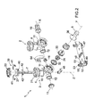
- each hydraulic assembly 2 comprises a casing 4 with a hydraulic circuit 5; a shutter 6 which acts on circuit 5 and is operated by actuator assembly 3; and a movable piston 7 inserted partly in circuit 5 and connected in use to the drain valve, and more specifically to a valve body of the drain valve.
- Casing 4 comprises a hollow body 10 having an inlet 11 and outlet 12, e.g. substantially aligned along an axis X and on opposite sides of body 10; and, internally, body 10 has a slide chamber 13 and a pressure chamber 14, which, for example, are substantially cylindrical, extend along respective perpendicular axes Z and Y, and are connected hydraulically to each other by a channel 15.
- Inlet 11 is connected to a water feed conduit 16 (in turn connected to the water mains feeding the flush tank); outlet 12 is closed by a cap 17; when device 1 comprises two hydraulic assemblies 2 and therefore two bodies 10, the hydraulic assemblies 2 are connected hydraulically in series, so that body 10 of the first hydraulic assembly 2 has its inlet 11 connected to a feed conduit 16, and its outlet 12 connected by a further feed conduit 16 to inlet 11 of body 10 of the second hydraulic assembly 2; and outlet 12 of body 10 of the second hydraulic assembly 2 is closed by cap 17.
- Slide chamber 13 extends (substantially vertically in use) along axis Z, and is bounded by a lateral, e.g. substantially cylindrical, wall 18; slide chamber 13 has an open top end 21 with one or more outlet holes 22, and a bottom end 23 opposite top end 21 and closed by a bottom wall 24; bottom wall 24 has a central through hole 25 communicating with channel 15 and therefore with pressure chamber 14.
- Pressure chamber 14 extends along axis Y and houses a cap 26, which is positioned crosswise to pressure chamber 14 to divide pressure chamber 14 into two adjacent zones 27, 28 aligned along axis Y; zone 27 communicates with inlet 11 and, via a passage 29 in an end wall of pressure chamber 14, with channel 15; passage 29 is bounded by a sealing seat 30 defined, for example, by a front edge of an annular collar; and zone 28 has a vent hole 31 opposite passage 29.
- Cap 26 advantageously has a substantially rigid disk body made of plastic, and a flexible, e.g. rubber, hood 32, the outer peripheral edge of which contacts a lateral wall of pressure chamber 14.
- Cap 26 is movable inside pressure chamber 14 to selectively open/close passage 29. For example, guided by a guide 33, cap 26 slides along axis Y for selectively resting against sealing seat 30 (thus closing passage 29) and releasing sealing seat 30 (thus opening passage 29). Cap 26 has two opposite faces facing zones 27 and 28 respectively.
- Zones 27 and 28 communicate via at least one service conduit 34 formed, for example, through cap 26.
- Shutter 6 is movable to allow or cut off water flow through vent hole 31. More specifically, shutter 6 cooperates with, and is movable to selectively open/close, vent hole 31. For example, shutter 6 is fitted to a lever 36 hinged to body 10 and connected to actuator assembly 3.
- Actuator assembly 3 is generally designed to move lever 36, or more generally speaking shutter 6, to open/close vent hole 31, and so comprises a mechanism for moving shutter 6 (e.g. together with lever 36) from a closed position, in which shutter 6 closes vent hole 31, to an open position, in which shutter 6 leaves vent hole 31 open, and then restoring lever 36 and shutter 6 to the closed position.
- Actuator assembly 3 may be a known type, such as a pneumatic actuator assembly as shown in Figure 1 , or a mechanical or electromechanical actuator assembly, and may be either user-operated directly, e.g. by means of a pushbutton, or automatically, e.g. by a presence sensor.
- Piston 7 comprises a head 37 and a rod 38.
- Head 37 is housed in slide chamber 13, and has an annular gasket 39 surrounding head 37 and cooperating radially with lateral wall 18. More specifically, gasket 39 is housed in a peripheral groove 40 on head 37.
- Gasket 39 is substantially annular, and comprises a number of sectors 41, which cooperate with and slide laterally with respect to one another to alter the radial size of gasket 39.
- each sector 41 has two opposite stepped portions 42 located at respective angularly opposite ends of sector 41; and angularly adjacent sectors 41 are connected to one another by respective axially overlapping stepped portions 42 cooperating radially with one another.
- Rod 38 projects axially from head 37, and is inserted loosely through hole 25, so as not to close hole 25 completely, and so as to define about rod 38 an annular passage communicating with channel 15; rod 38 is then inserted inside a seat 45 through body 10; between rod 38 and seat 45, there is a small radial clearance (smaller than that between rod 38 and hole 25); and rod 38 projects downwards from seat 45 and body 10, and has a hook 46 which hooks onto the valve body of the drain valve.
- Device 1 advantageously comprises a support 47, which fits to the flush tank and supports hydraulic assemblies 2.
- Support 47 comprises a plate 48, which has fasteners 49 for fixing plate 48 to the flush tank, and supporting members 50 located on the top face of plate 48 to receive and support one or more hydraulic assemblies 2.
- each supporting member 50 has a seat 51 shaped to receive a tubular member and/or a flange on the tubular member. More specifically, seat 51 has a curved bottom surface 52, on which a tubular member rests, and which has a slot 53 in which to insert a flange on the tubular member.
- support 47 has three substantially aligned supporting members 50; and one of supporting members 50, e.g. the middle one, has a fastening bracket 54, which fits onto plate 48 to close the top of seat 51 of supporting member 50.
- device 1 is connected to the water mains by feed conduit 16.
- each hydraulic assembly 2 assumes a rest position ( Figure 3 ), in which vent hole 31 is closed by shutter 6, passage 29 is closed by cap 26, and piston 7 rests on bottom wall 24 of slide chamber 13.
- the water fed into hydraulic assembly 2 through inlet 11 fills both zones 27, 28 of pressure chamber 14, thus balancing the pressure on the opposite faces of cap 26, which therefore remains positioned against sealing seat 30 to prevent water from flowing into channel 15 and reaching slide chamber 13.
- actuator assembly 3 moves lever 36 of respective hydraulic assembly 2 to move shutter 6 and open vent hole 31.
- Hydraulic assembly 2 assumes a flush position ( Figure 4 ), in which shutter 6 leaves vent hole 31 open; the water flows out through vent hole 31, so the water pressure in zone 27 is higher than that in zone 28, and pushes cap 26 away from sealing seat 30 and towards vent hole 31 to open passage 29. The water then flows along channel 15 to slide chamber 13, thus pushing head 37 of piston 7 upwards, and raising piston 7 together with the valve body of the drain valve.
- the water then flows out of hydraulic assembly 2 through outlet holes 22 and into the flush tank; and part of the water may also seep into seat 45 of rod 38. Water is allowed to flow out through outlet holes 22 by the water pressure in slide chamber 13 expanding and parting sectors 41 of gasket 39, to allow water to flow between sectors 41 to outlet holes 22.
- hydraulic assembly 2 moves back to the rest position : shutter 6 again closes vent hole 31, and cap 26 again closes passage 29; slide chamber 13 empties, piston 7 moves down, and the drain valve closes.
- shutter 6 is located remotely with respect to hydraulic assembly 2, and, more specifically, is integrated in actuator assembly 3 and, as opposed to directly contacting vent hole 31, cooperates with an auxiliary hole 61 communicating with vent hole 31, to allow or cut off water flow through vent hole 31.
- actuator assembly 3 (or each actuator assembly 3) comprises a hollow supporting body 62, which is connected hydraulically to hydraulic assembly 2 by a tube 63, and supports shutter 6, and a pushbutton 64 connected to and for moving shutter 6.
- Chamber 66 has an inlet 74 formed, for example, in a lateral wall 75 of chamber 66; and tube 63 connects inlet 74 to vent hole 31 of hydraulic assembly 2.
- Member 76 for example, comprises a flexible membrane 81 with a peripheral edge 82 fixed to lateral wall 75 of chamber 66, and a rigid insert 83 located in zone 78 and guided by a guide 84 which also closes chamber 66. Auxiliary hole 61 and inlet 74 are located in zone 77.
- shutter 6 is normally set to a closed position ( Figure 6 ) closing auxiliary hole 61 to prevent water flow from chamber 66 into chamber 65.
- Shutter 6 is kept in the closed position by member 76 and by the pressure of the water filling both zones 77, 78 and exerting the same pressure on the opposite faces of member 76.
Landscapes
- Engineering & Computer Science (AREA)
- Mechanical Engineering (AREA)
- Aviation & Aerospace Engineering (AREA)
- Health & Medical Sciences (AREA)
- Life Sciences & Earth Sciences (AREA)
- Hydrology & Water Resources (AREA)
- Public Health (AREA)
- Water Supply & Treatment (AREA)
- Fluid-Driven Valves (AREA)
- Sliding Valves (AREA)
- Self-Closing Valves And Venting Or Aerating Valves (AREA)
- Sanitary Device For Flush Toilet (AREA)
Applications Claiming Priority (1)
| Application Number | Priority Date | Filing Date | Title |
|---|---|---|---|
| IT001209A ITMI20121209A1 (it) | 2012-07-11 | 2012-07-11 | Dispositivo di comando di una valvola di scarico di una cassetta di risciacquo |
Publications (3)
| Publication Number | Publication Date |
|---|---|
| EP2685014A1 true EP2685014A1 (de) | 2014-01-15 |
| EP2685014A8 EP2685014A8 (de) | 2014-07-09 |
| EP2685014B1 EP2685014B1 (de) | 2016-11-02 |
Family
ID=46758875
Family Applications (1)
| Application Number | Title | Priority Date | Filing Date |
|---|---|---|---|
| EP13398009.4A Not-in-force EP2685014B1 (de) | 2012-07-11 | 2013-07-10 | Steuerungsvorrichtung für ein Ablassventil eines Spültanks |
Country Status (5)
| Country | Link |
|---|---|
| EP (1) | EP2685014B1 (de) |
| AU (1) | AU2013206761A1 (de) |
| IL (1) | IL227392A0 (de) |
| IT (1) | ITMI20121209A1 (de) |
| RU (1) | RU2013132017A (de) |
Cited By (1)
| Publication number | Priority date | Publication date | Assignee | Title |
|---|---|---|---|---|
| EP4242387A1 (de) * | 2022-03-08 | 2023-09-13 | Kohler (China) Investment Co. Ltd. | Verborgener wassertank zur anpassung verschiedener antriebstafeln |
Citations (4)
| Publication number | Priority date | Publication date | Assignee | Title |
|---|---|---|---|---|
| DE2519871A1 (de) * | 1975-05-03 | 1976-11-11 | Reed International Ltd | Schwimmergesteuertes ventil |
| US20040025238A1 (en) * | 2000-11-20 | 2004-02-12 | Arichell Technologies, Inc. | Toilet flusher with novel valves and controls |
| EP1582637A2 (de) * | 2004-03-30 | 2005-10-05 | VALSIR S.p.A. | Betätigungsvorrichtung eines Ablaufventils eines Spülkastens und Spülkasten mit einer solchen Vorrichtung |
| EP1749941A1 (de) * | 2005-08-01 | 2007-02-07 | Sanimatic Ag | Hydraulischer Aktuator, insbesondere für eine Spülsteuerung |
-
2012
- 2012-07-11 IT IT001209A patent/ITMI20121209A1/it unknown
-
2013
- 2013-07-09 IL IL227392A patent/IL227392A0/en unknown
- 2013-07-09 AU AU2013206761A patent/AU2013206761A1/en not_active Abandoned
- 2013-07-10 EP EP13398009.4A patent/EP2685014B1/de not_active Not-in-force
- 2013-07-10 RU RU2013132017/13A patent/RU2013132017A/ru not_active Application Discontinuation
Patent Citations (4)
| Publication number | Priority date | Publication date | Assignee | Title |
|---|---|---|---|---|
| DE2519871A1 (de) * | 1975-05-03 | 1976-11-11 | Reed International Ltd | Schwimmergesteuertes ventil |
| US20040025238A1 (en) * | 2000-11-20 | 2004-02-12 | Arichell Technologies, Inc. | Toilet flusher with novel valves and controls |
| EP1582637A2 (de) * | 2004-03-30 | 2005-10-05 | VALSIR S.p.A. | Betätigungsvorrichtung eines Ablaufventils eines Spülkastens und Spülkasten mit einer solchen Vorrichtung |
| EP1749941A1 (de) * | 2005-08-01 | 2007-02-07 | Sanimatic Ag | Hydraulischer Aktuator, insbesondere für eine Spülsteuerung |
Cited By (1)
| Publication number | Priority date | Publication date | Assignee | Title |
|---|---|---|---|---|
| EP4242387A1 (de) * | 2022-03-08 | 2023-09-13 | Kohler (China) Investment Co. Ltd. | Verborgener wassertank zur anpassung verschiedener antriebstafeln |
Also Published As
| Publication number | Publication date |
|---|---|
| ITMI20121209A1 (it) | 2014-01-12 |
| RU2013132017A (ru) | 2015-01-20 |
| AU2013206761A1 (en) | 2014-01-30 |
| EP2685014A8 (de) | 2014-07-09 |
| EP2685014B1 (de) | 2016-11-02 |
| IL227392A0 (en) | 2013-12-31 |
Similar Documents
| Publication | Publication Date | Title |
|---|---|---|
| US6934976B2 (en) | Toilet flusher with novel valves and controls | |
| US9695582B2 (en) | Drainage fitting for a cistern | |
| EP3325730B1 (de) | Sanitärartikel | |
| EP3133216B1 (de) | Toilettenspülungssystem | |
| CA2588769C (en) | Vacuum sewer system | |
| JP6031603B2 (ja) | 浮力のある可動浮き部材を内蔵したトイレ排水弁組立体 | |
| EP2685014B1 (de) | Steuerungsvorrichtung für ein Ablassventil eines Spültanks | |
| JP5198286B2 (ja) | 液圧作動装置 | |
| EP3156549B1 (de) | Starrer kolbenschieber mit einem solenoid | |
| US2971525A (en) | Float-operated valve | |
| EP1582637B1 (de) | Betätigungsvorrichtung eines Ablaufventils eines Spülkastens und Spülkasten mit einer solchen Vorrichtung | |
| JP2004332470A (ja) | ロータンク装置における排水弁の制御方法およびその装置 | |
| JP4292060B2 (ja) | 常閉形フロート式オートドレン | |
| KR20160145392A (ko) | 전자제어 양변기 및 비데 일체형 양변기용 배수밸브장치 | |
| CN210713100U (zh) | 一种手动电动一体化的排水装置 | |
| IL156012A (en) | Toilet flusher with novel valves and controls | |
| KR200421785Y1 (ko) | 소변기용 자동 급수 장치 | |
| EP3452666B1 (de) | Betätigung für spülventil | |
| JP2001081819A (ja) | 給水栓 | |
| EP1491691A2 (de) | Pneumatische Vorrichtung zur Aktivierung eines Ablaufventils eines Spülkastens | |
| EP1258570A2 (de) | Doppelfunktionzuführvorrichting für Toilettenspülkästen | |
| KR20120011995A (ko) | 절수형 플래시밸브 | |
| HK1256291B (en) | Sanitary-ware |
Legal Events
| Date | Code | Title | Description |
|---|---|---|---|
| PUAI | Public reference made under article 153(3) epc to a published international application that has entered the european phase |
Free format text: ORIGINAL CODE: 0009012 |
|
| AK | Designated contracting states |
Kind code of ref document: A1 Designated state(s): AL AT BE BG CH CY CZ DE DK EE ES FI FR GB GR HR HU IE IS IT LI LT LU LV MC MK MT NL NO PL PT RO RS SE SI SK SM TR |
|
| AX | Request for extension of the european patent |
Extension state: BA ME |
|
| 17P | Request for examination filed |
Effective date: 20140714 |
|
| RBV | Designated contracting states (corrected) |
Designated state(s): AL AT BE BG CH CY CZ DE DK EE ES FI FR GB GR HR HU IE IS IT LI LT LU LV MC MK MT NL NO PL PT RO RS SE SI SK SM TR |
|
| GRAP | Despatch of communication of intention to grant a patent |
Free format text: ORIGINAL CODE: EPIDOSNIGR1 |
|
| RIC1 | Information provided on ipc code assigned before grant |
Ipc: E03D 5/02 20060101AFI20160429BHEP |
|
| INTG | Intention to grant announced |
Effective date: 20160530 |
|
| GRAS | Grant fee paid |
Free format text: ORIGINAL CODE: EPIDOSNIGR3 |
|
| GRAA | (expected) grant |
Free format text: ORIGINAL CODE: 0009210 |
|
| AK | Designated contracting states |
Kind code of ref document: B1 Designated state(s): AL AT BE BG CH CY CZ DE DK EE ES FI FR GB GR HR HU IE IS IT LI LT LU LV MC MK MT NL NO PL PT RO RS SE SI SK SM TR |
|
| REG | Reference to a national code |
Ref country code: GB Ref legal event code: FG4D |
|
| REG | Reference to a national code |
Ref country code: AT Ref legal event code: REF Ref document number: 842009 Country of ref document: AT Kind code of ref document: T Effective date: 20161115 Ref country code: CH Ref legal event code: EP |
|
| REG | Reference to a national code |
Ref country code: IE Ref legal event code: FG4D |
|
| REG | Reference to a national code |
Ref country code: DE Ref legal event code: R096 Ref document number: 602013013444 Country of ref document: DE |
|
| PG25 | Lapsed in a contracting state [announced via postgrant information from national office to epo] |
Ref country code: LV Free format text: LAPSE BECAUSE OF FAILURE TO SUBMIT A TRANSLATION OF THE DESCRIPTION OR TO PAY THE FEE WITHIN THE PRESCRIBED TIME-LIMIT Effective date: 20161102 |
|
| REG | Reference to a national code |
Ref country code: NL Ref legal event code: MP Effective date: 20161102 |
|
| REG | Reference to a national code |
Ref country code: LT Ref legal event code: MG4D |
|
| REG | Reference to a national code |
Ref country code: AT Ref legal event code: MK05 Ref document number: 842009 Country of ref document: AT Kind code of ref document: T Effective date: 20161102 |
|
| PG25 | Lapsed in a contracting state [announced via postgrant information from national office to epo] |
Ref country code: NO Free format text: LAPSE BECAUSE OF FAILURE TO SUBMIT A TRANSLATION OF THE DESCRIPTION OR TO PAY THE FEE WITHIN THE PRESCRIBED TIME-LIMIT Effective date: 20170202 Ref country code: NL Free format text: LAPSE BECAUSE OF FAILURE TO SUBMIT A TRANSLATION OF THE DESCRIPTION OR TO PAY THE FEE WITHIN THE PRESCRIBED TIME-LIMIT Effective date: 20161102 Ref country code: SE Free format text: LAPSE BECAUSE OF FAILURE TO SUBMIT A TRANSLATION OF THE DESCRIPTION OR TO PAY THE FEE WITHIN THE PRESCRIBED TIME-LIMIT Effective date: 20161102 Ref country code: LT Free format text: LAPSE BECAUSE OF FAILURE TO SUBMIT A TRANSLATION OF THE DESCRIPTION OR TO PAY THE FEE WITHIN THE PRESCRIBED TIME-LIMIT Effective date: 20161102 |
|
| PG25 | Lapsed in a contracting state [announced via postgrant information from national office to epo] |
Ref country code: FI Free format text: LAPSE BECAUSE OF FAILURE TO SUBMIT A TRANSLATION OF THE DESCRIPTION OR TO PAY THE FEE WITHIN THE PRESCRIBED TIME-LIMIT Effective date: 20161102 Ref country code: IS Free format text: LAPSE BECAUSE OF FAILURE TO SUBMIT A TRANSLATION OF THE DESCRIPTION OR TO PAY THE FEE WITHIN THE PRESCRIBED TIME-LIMIT Effective date: 20170302 Ref country code: PL Free format text: LAPSE BECAUSE OF FAILURE TO SUBMIT A TRANSLATION OF THE DESCRIPTION OR TO PAY THE FEE WITHIN THE PRESCRIBED TIME-LIMIT Effective date: 20161102 Ref country code: PT Free format text: LAPSE BECAUSE OF FAILURE TO SUBMIT A TRANSLATION OF THE DESCRIPTION OR TO PAY THE FEE WITHIN THE PRESCRIBED TIME-LIMIT Effective date: 20170302 Ref country code: HR Free format text: LAPSE BECAUSE OF FAILURE TO SUBMIT A TRANSLATION OF THE DESCRIPTION OR TO PAY THE FEE WITHIN THE PRESCRIBED TIME-LIMIT Effective date: 20161102 Ref country code: RS Free format text: LAPSE BECAUSE OF FAILURE TO SUBMIT A TRANSLATION OF THE DESCRIPTION OR TO PAY THE FEE WITHIN THE PRESCRIBED TIME-LIMIT Effective date: 20161102 Ref country code: ES Free format text: LAPSE BECAUSE OF FAILURE TO SUBMIT A TRANSLATION OF THE DESCRIPTION OR TO PAY THE FEE WITHIN THE PRESCRIBED TIME-LIMIT Effective date: 20161102 Ref country code: AT Free format text: LAPSE BECAUSE OF FAILURE TO SUBMIT A TRANSLATION OF THE DESCRIPTION OR TO PAY THE FEE WITHIN THE PRESCRIBED TIME-LIMIT Effective date: 20161102 |
|
| REG | Reference to a national code |
Ref country code: FR Ref legal event code: PLFP Year of fee payment: 5 |
|
| PG25 | Lapsed in a contracting state [announced via postgrant information from national office to epo] |
Ref country code: EE Free format text: LAPSE BECAUSE OF FAILURE TO SUBMIT A TRANSLATION OF THE DESCRIPTION OR TO PAY THE FEE WITHIN THE PRESCRIBED TIME-LIMIT Effective date: 20161102 Ref country code: SK Free format text: LAPSE BECAUSE OF FAILURE TO SUBMIT A TRANSLATION OF THE DESCRIPTION OR TO PAY THE FEE WITHIN THE PRESCRIBED TIME-LIMIT Effective date: 20161102 Ref country code: DK Free format text: LAPSE BECAUSE OF FAILURE TO SUBMIT A TRANSLATION OF THE DESCRIPTION OR TO PAY THE FEE WITHIN THE PRESCRIBED TIME-LIMIT Effective date: 20161102 Ref country code: CZ Free format text: LAPSE BECAUSE OF FAILURE TO SUBMIT A TRANSLATION OF THE DESCRIPTION OR TO PAY THE FEE WITHIN THE PRESCRIBED TIME-LIMIT Effective date: 20161102 Ref country code: RO Free format text: LAPSE BECAUSE OF FAILURE TO SUBMIT A TRANSLATION OF THE DESCRIPTION OR TO PAY THE FEE WITHIN THE PRESCRIBED TIME-LIMIT Effective date: 20161102 |
|
| REG | Reference to a national code |
Ref country code: DE Ref legal event code: R097 Ref document number: 602013013444 Country of ref document: DE |
|
| PG25 | Lapsed in a contracting state [announced via postgrant information from national office to epo] |
Ref country code: SM Free format text: LAPSE BECAUSE OF FAILURE TO SUBMIT A TRANSLATION OF THE DESCRIPTION OR TO PAY THE FEE WITHIN THE PRESCRIBED TIME-LIMIT Effective date: 20161102 Ref country code: BE Free format text: LAPSE BECAUSE OF FAILURE TO SUBMIT A TRANSLATION OF THE DESCRIPTION OR TO PAY THE FEE WITHIN THE PRESCRIBED TIME-LIMIT Effective date: 20161102 Ref country code: BG Free format text: LAPSE BECAUSE OF FAILURE TO SUBMIT A TRANSLATION OF THE DESCRIPTION OR TO PAY THE FEE WITHIN THE PRESCRIBED TIME-LIMIT Effective date: 20170202 |
|
| PLBE | No opposition filed within time limit |
Free format text: ORIGINAL CODE: 0009261 |
|
| STAA | Information on the status of an ep patent application or granted ep patent |
Free format text: STATUS: NO OPPOSITION FILED WITHIN TIME LIMIT |
|
| 26N | No opposition filed |
Effective date: 20170803 |
|
| PGFP | Annual fee paid to national office [announced via postgrant information from national office to epo] |
Ref country code: FR Payment date: 20170727 Year of fee payment: 5 |
|
| PG25 | Lapsed in a contracting state [announced via postgrant information from national office to epo] |
Ref country code: SI Free format text: LAPSE BECAUSE OF FAILURE TO SUBMIT A TRANSLATION OF THE DESCRIPTION OR TO PAY THE FEE WITHIN THE PRESCRIBED TIME-LIMIT Effective date: 20161102 |
|
| REG | Reference to a national code |
Ref country code: CH Ref legal event code: PL |
|
| GBPC | Gb: european patent ceased through non-payment of renewal fee |
Effective date: 20170710 |
|
| REG | Reference to a national code |
Ref country code: IE Ref legal event code: MM4A |
|
| PG25 | Lapsed in a contracting state [announced via postgrant information from national office to epo] |
Ref country code: LI Free format text: LAPSE BECAUSE OF NON-PAYMENT OF DUE FEES Effective date: 20170731 Ref country code: IE Free format text: LAPSE BECAUSE OF NON-PAYMENT OF DUE FEES Effective date: 20170710 Ref country code: GB Free format text: LAPSE BECAUSE OF NON-PAYMENT OF DUE FEES Effective date: 20170710 Ref country code: CH Free format text: LAPSE BECAUSE OF NON-PAYMENT OF DUE FEES Effective date: 20170731 |
|
| PG25 | Lapsed in a contracting state [announced via postgrant information from national office to epo] |
Ref country code: LU Free format text: LAPSE BECAUSE OF NON-PAYMENT OF DUE FEES Effective date: 20170710 |
|
| PG25 | Lapsed in a contracting state [announced via postgrant information from national office to epo] |
Ref country code: IT Free format text: LAPSE BECAUSE OF NON-PAYMENT OF DUE FEES Effective date: 20170710 |
|
| PG25 | Lapsed in a contracting state [announced via postgrant information from national office to epo] |
Ref country code: MT Free format text: LAPSE BECAUSE OF NON-PAYMENT OF DUE FEES Effective date: 20170710 |
|
| PG25 | Lapsed in a contracting state [announced via postgrant information from national office to epo] |
Ref country code: FR Free format text: LAPSE BECAUSE OF NON-PAYMENT OF DUE FEES Effective date: 20180731 |
|
| PG25 | Lapsed in a contracting state [announced via postgrant information from national office to epo] |
Ref country code: MC Free format text: LAPSE BECAUSE OF FAILURE TO SUBMIT A TRANSLATION OF THE DESCRIPTION OR TO PAY THE FEE WITHIN THE PRESCRIBED TIME-LIMIT Effective date: 20161102 Ref country code: HU Free format text: LAPSE BECAUSE OF FAILURE TO SUBMIT A TRANSLATION OF THE DESCRIPTION OR TO PAY THE FEE WITHIN THE PRESCRIBED TIME-LIMIT; INVALID AB INITIO Effective date: 20130710 |
|
| PG25 | Lapsed in a contracting state [announced via postgrant information from national office to epo] |
Ref country code: CY Free format text: LAPSE BECAUSE OF NON-PAYMENT OF DUE FEES Effective date: 20161102 |
|
| PGFP | Annual fee paid to national office [announced via postgrant information from national office to epo] |
Ref country code: DE Payment date: 20190731 Year of fee payment: 7 |
|
| PG25 | Lapsed in a contracting state [announced via postgrant information from national office to epo] |
Ref country code: MK Free format text: LAPSE BECAUSE OF FAILURE TO SUBMIT A TRANSLATION OF THE DESCRIPTION OR TO PAY THE FEE WITHIN THE PRESCRIBED TIME-LIMIT Effective date: 20161102 |
|
| PG25 | Lapsed in a contracting state [announced via postgrant information from national office to epo] |
Ref country code: TR Free format text: LAPSE BECAUSE OF FAILURE TO SUBMIT A TRANSLATION OF THE DESCRIPTION OR TO PAY THE FEE WITHIN THE PRESCRIBED TIME-LIMIT Effective date: 20161102 |
|
| PG25 | Lapsed in a contracting state [announced via postgrant information from national office to epo] |
Ref country code: GR Free format text: LAPSE BECAUSE OF FAILURE TO SUBMIT A TRANSLATION OF THE DESCRIPTION OR TO PAY THE FEE WITHIN THE PRESCRIBED TIME-LIMIT Effective date: 20161102 |
|
| PG25 | Lapsed in a contracting state [announced via postgrant information from national office to epo] |
Ref country code: AL Free format text: LAPSE BECAUSE OF FAILURE TO SUBMIT A TRANSLATION OF THE DESCRIPTION OR TO PAY THE FEE WITHIN THE PRESCRIBED TIME-LIMIT Effective date: 20161102 |
|
| REG | Reference to a national code |
Ref country code: DE Ref legal event code: R119 Ref document number: 602013013444 Country of ref document: DE |
|
| PG25 | Lapsed in a contracting state [announced via postgrant information from national office to epo] |
Ref country code: DE Free format text: LAPSE BECAUSE OF NON-PAYMENT OF DUE FEES Effective date: 20210202 |