EP2684590A1 - Wabenstruktur - Google Patents
Wabenstruktur Download PDFInfo
- Publication number
- EP2684590A1 EP2684590A1 EP12755689.2A EP12755689A EP2684590A1 EP 2684590 A1 EP2684590 A1 EP 2684590A1 EP 12755689 A EP12755689 A EP 12755689A EP 2684590 A1 EP2684590 A1 EP 2684590A1
- Authority
- EP
- European Patent Office
- Prior art keywords
- honeycomb
- honeycomb structure
- joining
- less
- joining portions
- Prior art date
- Legal status (The legal status is an assumption and is not a legal conclusion. Google has not performed a legal analysis and makes no representation as to the accuracy of the status listed.)
- Granted
Links
- 238000005304 joining Methods 0.000 claims abstract description 120
- 230000002093 peripheral effect Effects 0.000 claims abstract description 37
- 238000005192 partition Methods 0.000 claims abstract description 26
- 239000012530 fluid Substances 0.000 claims abstract description 9
- 239000000463 material Substances 0.000 description 51
- 238000000034 method Methods 0.000 description 34
- 239000002994 raw material Substances 0.000 description 21
- 238000002474 experimental method Methods 0.000 description 20
- 239000007789 gas Substances 0.000 description 18
- MWUXSHHQAYIFBG-UHFFFAOYSA-N nitrogen oxide Inorganic materials O=[N] MWUXSHHQAYIFBG-UHFFFAOYSA-N 0.000 description 18
- 238000000576 coating method Methods 0.000 description 17
- 239000003054 catalyst Substances 0.000 description 16
- 239000011148 porous material Substances 0.000 description 16
- 239000011248 coating agent Substances 0.000 description 15
- 229910010271 silicon carbide Inorganic materials 0.000 description 15
- 239000013618 particulate matter Substances 0.000 description 14
- HBMJWWWQQXIZIP-UHFFFAOYSA-N silicon carbide Chemical compound [Si+]#[C-] HBMJWWWQQXIZIP-UHFFFAOYSA-N 0.000 description 14
- XLYOFNOQVPJJNP-UHFFFAOYSA-N water Substances O XLYOFNOQVPJJNP-UHFFFAOYSA-N 0.000 description 12
- 229910001868 water Inorganic materials 0.000 description 12
- 238000010304 firing Methods 0.000 description 11
- 239000002585 base Substances 0.000 description 10
- 239000000919 ceramic Substances 0.000 description 10
- 230000007423 decrease Effects 0.000 description 10
- 238000001035 drying Methods 0.000 description 10
- 238000010438 heat treatment Methods 0.000 description 10
- 239000002245 particle Substances 0.000 description 10
- 239000011230 binding agent Substances 0.000 description 9
- 230000003247 decreasing effect Effects 0.000 description 8
- 239000002002 slurry Substances 0.000 description 8
- IJGRMHOSHXDMSA-UHFFFAOYSA-N Atomic nitrogen Chemical compound N#N IJGRMHOSHXDMSA-UHFFFAOYSA-N 0.000 description 6
- KDLHZDBZIXYQEI-UHFFFAOYSA-N Palladium Chemical compound [Pd] KDLHZDBZIXYQEI-UHFFFAOYSA-N 0.000 description 6
- 238000002485 combustion reaction Methods 0.000 description 6
- 239000002131 composite material Substances 0.000 description 6
- BASFCYQUMIYNBI-UHFFFAOYSA-N platinum Chemical compound [Pt] BASFCYQUMIYNBI-UHFFFAOYSA-N 0.000 description 6
- 239000011347 resin Substances 0.000 description 6
- 229920005989 resin Polymers 0.000 description 6
- 239000004094 surface-active agent Substances 0.000 description 6
- VYPSYNLAJGMNEJ-UHFFFAOYSA-N Silicium dioxide Chemical compound O=[Si]=O VYPSYNLAJGMNEJ-UHFFFAOYSA-N 0.000 description 5
- 239000004927 clay Substances 0.000 description 5
- 229920000609 methyl cellulose Polymers 0.000 description 5
- 239000001923 methylcellulose Substances 0.000 description 5
- 239000000203 mixture Substances 0.000 description 5
- CURLTUGMZLYLDI-UHFFFAOYSA-N Carbon dioxide Chemical compound O=C=O CURLTUGMZLYLDI-UHFFFAOYSA-N 0.000 description 4
- UGFAIRIUMAVXCW-UHFFFAOYSA-N Carbon monoxide Chemical compound [O+]#[C-] UGFAIRIUMAVXCW-UHFFFAOYSA-N 0.000 description 4
- XUIMIQQOPSSXEZ-UHFFFAOYSA-N Silicon Chemical compound [Si] XUIMIQQOPSSXEZ-UHFFFAOYSA-N 0.000 description 4
- 229910002091 carbon monoxide Inorganic materials 0.000 description 4
- 239000004568 cement Substances 0.000 description 4
- 230000008859 change Effects 0.000 description 4
- 239000008119 colloidal silica Substances 0.000 description 4
- 229910052878 cordierite Inorganic materials 0.000 description 4
- 229930195733 hydrocarbon Natural products 0.000 description 4
- 150000002430 hydrocarbons Chemical class 0.000 description 4
- -1 iron-chromium-aluminum Chemical compound 0.000 description 4
- 238000012545 processing Methods 0.000 description 4
- 239000010948 rhodium Substances 0.000 description 4
- SBEQWOXEGHQIMW-UHFFFAOYSA-N silicon Chemical compound [Si].[Si] SBEQWOXEGHQIMW-UHFFFAOYSA-N 0.000 description 4
- 238000004901 spalling Methods 0.000 description 4
- LYCAIKOWRPUZTN-UHFFFAOYSA-N Ethylene glycol Chemical compound OCCO LYCAIKOWRPUZTN-UHFFFAOYSA-N 0.000 description 3
- PNEYBMLMFCGWSK-UHFFFAOYSA-N aluminium oxide Inorganic materials [O-2].[O-2].[O-2].[Al+3].[Al+3] PNEYBMLMFCGWSK-UHFFFAOYSA-N 0.000 description 3
- 238000000429 assembly Methods 0.000 description 3
- 230000000712 assembly Effects 0.000 description 3
- 238000001354 calcination Methods 0.000 description 3
- 229910052570 clay Inorganic materials 0.000 description 3
- 239000002270 dispersing agent Substances 0.000 description 3
- 239000012784 inorganic fiber Substances 0.000 description 3
- 238000004898 kneading Methods 0.000 description 3
- 229910052751 metal Inorganic materials 0.000 description 3
- 239000002184 metal Substances 0.000 description 3
- 229910052757 nitrogen Inorganic materials 0.000 description 3
- 229910000510 noble metal Inorganic materials 0.000 description 3
- 230000003647 oxidation Effects 0.000 description 3
- 238000007254 oxidation reaction Methods 0.000 description 3
- 238000000746 purification Methods 0.000 description 3
- 230000009467 reduction Effects 0.000 description 3
- 239000004071 soot Substances 0.000 description 3
- 238000012360 testing method Methods 0.000 description 3
- 229910000838 Al alloy Inorganic materials 0.000 description 2
- 229910000505 Al2TiO5 Inorganic materials 0.000 description 2
- XKRFYHLGVUSROY-UHFFFAOYSA-N Argon Chemical compound [Ar] XKRFYHLGVUSROY-UHFFFAOYSA-N 0.000 description 2
- 229920002472 Starch Polymers 0.000 description 2
- GWEVSGVZZGPLCZ-UHFFFAOYSA-N Titan oxide Chemical class O=[Ti]=O GWEVSGVZZGPLCZ-UHFFFAOYSA-N 0.000 description 2
- JFBZPFYRPYOZCQ-UHFFFAOYSA-N [Li].[Al] Chemical compound [Li].[Al] JFBZPFYRPYOZCQ-UHFFFAOYSA-N 0.000 description 2
- 239000000654 additive Substances 0.000 description 2
- 229910052783 alkali metal Inorganic materials 0.000 description 2
- 150000001340 alkali metals Chemical group 0.000 description 2
- 229910052784 alkaline earth metal Inorganic materials 0.000 description 2
- 230000015572 biosynthetic process Effects 0.000 description 2
- 229910002092 carbon dioxide Inorganic materials 0.000 description 2
- 239000001569 carbon dioxide Substances 0.000 description 2
- 239000001913 cellulose Substances 0.000 description 2
- 229920002678 cellulose Polymers 0.000 description 2
- 229910010293 ceramic material Inorganic materials 0.000 description 2
- 238000005520 cutting process Methods 0.000 description 2
- 238000007604 dielectric heating drying Methods 0.000 description 2
- JSKIRARMQDRGJZ-UHFFFAOYSA-N dimagnesium dioxido-bis[(1-oxido-3-oxo-2,4,6,8,9-pentaoxa-1,3-disila-5,7-dialuminabicyclo[3.3.1]nonan-7-yl)oxy]silane Chemical compound [Mg++].[Mg++].[O-][Si]([O-])(O[Al]1O[Al]2O[Si](=O)O[Si]([O-])(O1)O2)O[Al]1O[Al]2O[Si](=O)O[Si]([O-])(O1)O2 JSKIRARMQDRGJZ-UHFFFAOYSA-N 0.000 description 2
- KZHJGOXRZJKJNY-UHFFFAOYSA-N dioxosilane;oxo(oxoalumanyloxy)alumane Chemical compound O=[Si]=O.O=[Si]=O.O=[Al]O[Al]=O.O=[Al]O[Al]=O.O=[Al]O[Al]=O KZHJGOXRZJKJNY-UHFFFAOYSA-N 0.000 description 2
- 239000010419 fine particle Substances 0.000 description 2
- 238000007602 hot air drying Methods 0.000 description 2
- 229910052744 lithium Inorganic materials 0.000 description 2
- 238000004519 manufacturing process Methods 0.000 description 2
- 230000007246 mechanism Effects 0.000 description 2
- QSHDDOUJBYECFT-UHFFFAOYSA-N mercury Chemical compound [Hg] QSHDDOUJBYECFT-UHFFFAOYSA-N 0.000 description 2
- 229910052753 mercury Inorganic materials 0.000 description 2
- 229910052863 mullite Inorganic materials 0.000 description 2
- 229910052763 palladium Inorganic materials 0.000 description 2
- 229910052697 platinum Inorganic materials 0.000 description 2
- 229910052700 potassium Inorganic materials 0.000 description 2
- 238000002360 preparation method Methods 0.000 description 2
- AABBHSMFGKYLKE-SNAWJCMRSA-N propan-2-yl (e)-but-2-enoate Chemical compound C\C=C\C(=O)OC(C)C AABBHSMFGKYLKE-SNAWJCMRSA-N 0.000 description 2
- 230000001105 regulatory effect Effects 0.000 description 2
- 229910052703 rhodium Inorganic materials 0.000 description 2
- MHOVAHRLVXNVSD-UHFFFAOYSA-N rhodium atom Chemical compound [Rh] MHOVAHRLVXNVSD-UHFFFAOYSA-N 0.000 description 2
- 239000010703 silicon Substances 0.000 description 2
- 229910052710 silicon Inorganic materials 0.000 description 2
- 239000011863 silicon-based powder Substances 0.000 description 2
- 229910052708 sodium Inorganic materials 0.000 description 2
- 229910052596 spinel Inorganic materials 0.000 description 2
- 239000011029 spinel Substances 0.000 description 2
- 239000008107 starch Substances 0.000 description 2
- 235000019698 starch Nutrition 0.000 description 2
- 229920002134 Carboxymethyl cellulose Polymers 0.000 description 1
- 239000004375 Dextrin Substances 0.000 description 1
- 229920001353 Dextrin Polymers 0.000 description 1
- 229920000663 Hydroxyethyl cellulose Polymers 0.000 description 1
- 239000004354 Hydroxyethyl cellulose Substances 0.000 description 1
- 239000004372 Polyvinyl alcohol Substances 0.000 description 1
- BQCADISMDOOEFD-UHFFFAOYSA-N Silver Chemical class [Ag] BQCADISMDOOEFD-UHFFFAOYSA-N 0.000 description 1
- 229910021536 Zeolite Inorganic materials 0.000 description 1
- 229910052786 argon Inorganic materials 0.000 description 1
- 230000003139 buffering effect Effects 0.000 description 1
- 229910052791 calcium Inorganic materials 0.000 description 1
- 239000001768 carboxy methyl cellulose Substances 0.000 description 1
- 235000010948 carboxy methyl cellulose Nutrition 0.000 description 1
- 239000008112 carboxymethyl-cellulose Substances 0.000 description 1
- 230000003197 catalytic effect Effects 0.000 description 1
- 235000010980 cellulose Nutrition 0.000 description 1
- 238000006243 chemical reaction Methods 0.000 description 1
- 239000000470 constituent Substances 0.000 description 1
- 235000019425 dextrin Nutrition 0.000 description 1
- 235000014113 dietary fatty acids Nutrition 0.000 description 1
- HNPSIPDUKPIQMN-UHFFFAOYSA-N dioxosilane;oxo(oxoalumanyloxy)alumane Chemical class O=[Si]=O.O=[Al]O[Al]=O HNPSIPDUKPIQMN-UHFFFAOYSA-N 0.000 description 1
- 238000005516 engineering process Methods 0.000 description 1
- 238000001125 extrusion Methods 0.000 description 1
- 239000000194 fatty acid Substances 0.000 description 1
- 229930195729 fatty acid Natural products 0.000 description 1
- 150000004665 fatty acids Chemical class 0.000 description 1
- 230000004907 flux Effects 0.000 description 1
- 239000000446 fuel Substances 0.000 description 1
- 239000011521 glass Substances 0.000 description 1
- 235000019447 hydroxyethyl cellulose Nutrition 0.000 description 1
- 238000011835 investigation Methods 0.000 description 1
- 238000011068 loading method Methods 0.000 description 1
- 238000012986 modification Methods 0.000 description 1
- 230000004048 modification Effects 0.000 description 1
- QGLKJKCYBOYXKC-UHFFFAOYSA-N nonaoxidotritungsten Chemical class O=[W]1(=O)O[W](=O)(=O)O[W](=O)(=O)O1 QGLKJKCYBOYXKC-UHFFFAOYSA-N 0.000 description 1
- 229920002451 polyvinyl alcohol Polymers 0.000 description 1
- 235000019422 polyvinyl alcohol Nutrition 0.000 description 1
- 239000000843 powder Substances 0.000 description 1
- 230000035939 shock Effects 0.000 description 1
- 239000000741 silica gel Substances 0.000 description 1
- 229910002027 silica gel Inorganic materials 0.000 description 1
- 229910052709 silver Inorganic materials 0.000 description 1
- 239000004332 silver Chemical class 0.000 description 1
- 239000000344 soap Substances 0.000 description 1
- 150000005846 sugar alcohols Polymers 0.000 description 1
- 229910001930 tungsten oxide Inorganic materials 0.000 description 1
- 229910052720 vanadium Inorganic materials 0.000 description 1
- LEONUFNNVUYDNQ-UHFFFAOYSA-N vanadium atom Chemical class [V] LEONUFNNVUYDNQ-UHFFFAOYSA-N 0.000 description 1
- 239000010457 zeolite Substances 0.000 description 1
Images


Classifications
-
- B—PERFORMING OPERATIONS; TRANSPORTING
- B01—PHYSICAL OR CHEMICAL PROCESSES OR APPARATUS IN GENERAL
- B01D—SEPARATION
- B01D46/00—Filters or filtering processes specially modified for separating dispersed particles from gases or vapours
- B01D46/24—Particle separators, e.g. dust precipitators, using rigid hollow filter bodies
- B01D46/2403—Particle separators, e.g. dust precipitators, using rigid hollow filter bodies characterised by the physical shape or structure of the filtering element
- B01D46/2418—Honeycomb filters
- B01D46/2451—Honeycomb filters characterized by the geometrical structure, shape, pattern or configuration or parameters related to the geometry of the structure
- B01D46/2455—Honeycomb filters characterized by the geometrical structure, shape, pattern or configuration or parameters related to the geometry of the structure of the whole honeycomb or segments
-
- B—PERFORMING OPERATIONS; TRANSPORTING
- B01—PHYSICAL OR CHEMICAL PROCESSES OR APPARATUS IN GENERAL
- B01D—SEPARATION
- B01D46/00—Filters or filtering processes specially modified for separating dispersed particles from gases or vapours
- B01D46/24—Particle separators, e.g. dust precipitators, using rigid hollow filter bodies
- B01D46/2403—Particle separators, e.g. dust precipitators, using rigid hollow filter bodies characterised by the physical shape or structure of the filtering element
- B01D46/2418—Honeycomb filters
- B01D46/2451—Honeycomb filters characterized by the geometrical structure, shape, pattern or configuration or parameters related to the geometry of the structure
- B01D46/2478—Structures comprising honeycomb segments
-
- B—PERFORMING OPERATIONS; TRANSPORTING
- B01—PHYSICAL OR CHEMICAL PROCESSES OR APPARATUS IN GENERAL
- B01D—SEPARATION
- B01D46/00—Filters or filtering processes specially modified for separating dispersed particles from gases or vapours
- B01D46/24—Particle separators, e.g. dust precipitators, using rigid hollow filter bodies
- B01D46/2403—Particle separators, e.g. dust precipitators, using rigid hollow filter bodies characterised by the physical shape or structure of the filtering element
- B01D46/2418—Honeycomb filters
- B01D46/2451—Honeycomb filters characterized by the geometrical structure, shape, pattern or configuration or parameters related to the geometry of the structure
- B01D46/2482—Thickness, height, width, length or diameter
-
- B—PERFORMING OPERATIONS; TRANSPORTING
- B01—PHYSICAL OR CHEMICAL PROCESSES OR APPARATUS IN GENERAL
- B01D—SEPARATION
- B01D46/00—Filters or filtering processes specially modified for separating dispersed particles from gases or vapours
- B01D46/24—Particle separators, e.g. dust precipitators, using rigid hollow filter bodies
- B01D46/2403—Particle separators, e.g. dust precipitators, using rigid hollow filter bodies characterised by the physical shape or structure of the filtering element
- B01D46/2418—Honeycomb filters
- B01D46/2451—Honeycomb filters characterized by the geometrical structure, shape, pattern or configuration or parameters related to the geometry of the structure
- B01D46/2466—Honeycomb filters characterized by the geometrical structure, shape, pattern or configuration or parameters related to the geometry of the structure of the adhesive layers, i.e. joints between segments
-
- B—PERFORMING OPERATIONS; TRANSPORTING
- B01—PHYSICAL OR CHEMICAL PROCESSES OR APPARATUS IN GENERAL
- B01D—SEPARATION
- B01D46/00—Filters or filtering processes specially modified for separating dispersed particles from gases or vapours
- B01D46/24—Particle separators, e.g. dust precipitators, using rigid hollow filter bodies
- B01D46/2403—Particle separators, e.g. dust precipitators, using rigid hollow filter bodies characterised by the physical shape or structure of the filtering element
- B01D46/2418—Honeycomb filters
- B01D46/2451—Honeycomb filters characterized by the geometrical structure, shape, pattern or configuration or parameters related to the geometry of the structure
- B01D46/2486—Honeycomb filters characterized by the geometrical structure, shape, pattern or configuration or parameters related to the geometry of the structure characterised by the shapes or configurations
-
- C—CHEMISTRY; METALLURGY
- C04—CEMENTS; CONCRETE; ARTIFICIAL STONE; CERAMICS; REFRACTORIES
- C04B—LIME, MAGNESIA; SLAG; CEMENTS; COMPOSITIONS THEREOF, e.g. MORTARS, CONCRETE OR LIKE BUILDING MATERIALS; ARTIFICIAL STONE; CERAMICS; REFRACTORIES; TREATMENT OF NATURAL STONE
- C04B38/00—Porous mortars, concrete, artificial stone or ceramic ware; Preparation thereof
- C04B38/0006—Honeycomb structures
- C04B38/0016—Honeycomb structures assembled from subunits
-
- Y—GENERAL TAGGING OF NEW TECHNOLOGICAL DEVELOPMENTS; GENERAL TAGGING OF CROSS-SECTIONAL TECHNOLOGIES SPANNING OVER SEVERAL SECTIONS OF THE IPC; TECHNICAL SUBJECTS COVERED BY FORMER USPC CROSS-REFERENCE ART COLLECTIONS [XRACs] AND DIGESTS
- Y10—TECHNICAL SUBJECTS COVERED BY FORMER USPC
- Y10T—TECHNICAL SUBJECTS COVERED BY FORMER US CLASSIFICATION
- Y10T428/00—Stock material or miscellaneous articles
- Y10T428/24—Structurally defined web or sheet [e.g., overall dimension, etc.]
- Y10T428/24149—Honeycomb-like
Definitions
- the present invention relates to a honeycomb structure, and more particularly, it relates to a honeycomb structure in which an aspect ratio of each end surface is 1.2 or more, and cracks are not easily generated in each joining portion between filters, when a difference in temperature between the inside and the outside of the filter is made.
- a honeycomb structure made of a ceramic material has been used in a catalyst carrier which utilizes a catalytic action, a filter which collects a particulate matter in an exhaust gas, especially diesel fine particles (a diesel particulate filter hereinafter abbreviated to "DPF" sometimes), or the like for an internal combustion engine, a boiler, a chemical reaction device, a reformer for a fuel cell, or the like.
- DPF diesel particulate filter
- the honeycomb structure for use in this purpose usually has a plurality of cells which are defined by porous partition walls and which become through channels of a fluid.
- plugged portions are arranged in end portions of adjacent cells on opposite sides to form checkered patterns in end surfaces.
- a fluid to be treated flows into a cell which is not provided with the plugged portion in an inflow side end surface, i.e., the cell provided with the plugged portion in an outflow side end surface, passes through the porous partition wall, and is discharged from the adjacent cell, i.e., the cell which is provided with the plugged portion in the inflow side end surface and is not provided with the plugged portion in the outflow side end surface.
- the partition wall serves as the filter.
- a particulate matter hereinafter abbreviated to "PM" sometimes
- PM soot discharged from a diesel engine
- Such a honeycomb structure which is obtained by joining a plurality of honeycomb segments having a honeycomb shape together by a joining material.
- an example of the honeycomb structure is a honeycomb structure including a honeycomb structure section obtained by joining a plurality of honeycomb segments having a honeycomb shape together by a joining material, and an outer peripheral wall formed to cover an outer peripheral surface of this honeycomb structure section (see, e.g., Patent Document 1).
- a soot mass limit (hereinafter abbreviated to "SML" sometimes), a pressure loss and cost are important. It is considered that enhancement of the SML is accomplished by a technique of increasing a filter capacity or a technique of densifying a filter base material. However, in the former technique, the cost increases, and in the latter technique, the pressure loss increases. It is considered that the problem is solved by another method in which a base material such as SiC or SiN having a high thermal conductivity is used. However, these base materials have the disadvantage that a thermal expansion coefficient is large.
- the present invention has been developed in view of such problems of conventional technologies, and an object thereof is to provide a honeycomb structure having an aspect ratio (a long axis/a short axis) of 1.2 or more, in which the long axis is the longest portion on each of end surfaces of the honeycomb structure, and the short axis is the longest portion orthogonal to the long axis on the end surface, so that cracks are not easily generated.
- a honeycomb structure is provided as follows.
- a thickness of each of joining portions including corners present in the region of 25 mm or less from a straight line which passes through the center of a long axis and is parallel to a short axis is 0.5 mm or more and 5.0 mm or less, and hence generation of cracks due to a rapid temperature change in end surfaces of the honeycomb structure is suppressed.
- the corners are regions of the joining portions in the region of 10 mm or less from each intersection between the joining portion and the outer peripheral wall along a direction of the short axis.
- Fig. 1 is a plan view showing an end surface of a first embodiment of a honeycomb structure of the present invention
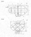
- Fig. 2 is a schematic perspective view showing the first embodiment of the honeycomb structure of the present invention
- Fig. 3 is a plan view showing an end surface of a honeycomb segment constituting the first embodiment of the honeycomb structure of the present invention. As shown in Fig. 1 to Fig.
- a honeycomb structure 100 of the present embodiment includes a honeycomb structure section 11 constituted of a plurality of honeycomb segments 10 each having porous partition walls 5 with which a plurality of cells 4 extending from one end surface 2 to the other end surface 2 are formed to become through channels of a fluid, and plugged portions 8 arranged in open frontal areas of the predetermined cells 4 in the one end surface 2 and open frontal areas of the remaining cells 4 in the other end surface 2; and an outer peripheral wall 20 formed to cover an outer peripheral surface of the honeycomb structure section 11.
- the honeycomb structure 100 of the present embodiment has an aspect ratio (a long axis/a short axis) of 1.2 or more, in which a long axis L L is the longest portion on each of the end surfaces, and a short axis L S is the longest portion orthogonal to the long axis L L on the end surface. That is, the aspect ratio of the long axis L L to the short axis L S is 1.2 or more.
- the honeycomb structure 100 when a DPF central portion has a high temperature and an outer peripheral portion has a low temperature, an expanding force is generated in the central portion, but in the outer peripheral portion, which is a lower temperature region, the expansive force is not generated so much as in the central portion, and hence a tensile stress is generated.
- the aspect ratio is 1.2 or more, the tensile stress is maximized in the central portion in a long axis direction.
- a joining portion 40 is present in this central portion, cracks are generated in the joining portion, because a peel strength of the joining portion is smaller than a base material strength.
- a joining material for use in the joining portions 40 a material having a predetermined Young's modulus is usually used to prevent the cracks from being generated. However, when the joining portions 40 are thin, the stress cannot be absorbed with the Young's modulus of the joining material, which results in the generation of the cracks.
- corners which are regions of the joining portions 40 in the region of 10 mm or less from each intersection between the joining portion 40 and the outer peripheral wall 20 along a direction of the short axis L S are present in the region of 25 mm or less from a straight line C L which passes through a center C of the long axis L L and is parallel to the short axis L S
- a thickness of each of the joining portions 40 including corners 50 "present in the region of 25 mm or less from the straight line which passes through the center of the long axis and is parallel to the short axis" is 0.5 mm or more.
- the thickness of each of the joining portions indicates a distance between side surfaces of the honeycomb segments joined by the joining portion.
- each of the joining portions including the corners indicates the whole joining portion present in a portion where the joining portion forming the corner is extended in a direction perpendicular to a thickness direction of the joining portion. That is, a slant portion S of Fig. 10 and Fig. 11 is indicated.
- the thickness of each of the joining portions 40 including the corners 50 present in the region of 25 mm or less from the straight line which passes through the center of the long axis and is parallel to the short axis is preferably from 0.5 to 5.0 mm, and further preferably from 1.0 to 1.5 mm. When the thickness is smaller than 0.5 mm, the cracks are easily generated at the corners due to a rapid temperature change.
- an area of the joining portion 40 increases in a cross section perpendicular to a passing direction of the exhaust gas (an extending direction of the cells), and hence when the exhaust gas is allowed to flow, a pressure loss increases sometimes.
- each of the joining portions 40 other than the joining portions including the corners 50 present in the region of 25 mm or less from the straight line which passes through the center of the long axis and is parallel to the short axis is preferably 1.5 mm or less, and further preferably from 0.1 to 1.5 mm.
- a force to join the honeycomb segments 10 decreases sometimes.
- the adjacent honeycomb segments 10 come in contact with each other sometimes.
- the thickness is larger than 1.5 mm, the area of the joining portion 40 increases in the cross section perpendicular to the passing direction of the exhaust gas (the cell extending direction). Therefore, when the exhaust gas is allowed to flow, the pressure loss increases sometimes. It is to be noted that the thickness of the joining portion 40 is a distance between the adjacent honeycomb segments 10.
- the thickness of each of the joining portions 40 other than the joining portions including the corners 50 present in the region of 25 mm or less from the straight line which passes through the center of the long axis and is parallel to the short axis is preferably smaller than the thickness of each of the joining portions including the corners 50 present in the region of 25 mm or less from the straight line which passes through the center of the long axis and is parallel to the short axis.
- the honeycomb structure for use in an exhaust gas purifying filter for an internal combustion engine or the like preferably has less pressure loss.
- An example of a method for decreasing the pressure loss of the honeycomb structure is a method of increasing an open area ratio of the end surface.
- the open area ratio can be increased by decreasing the thickness of each of the joining portions.
- the thickness of each of the joining portions 40 other than the joining portions including the corners 50 present in the region of 25 mm or less from the straight line which passes through the center of the long axis and is parallel to the short axis is smaller than the thickness of each of the joining portions including the corners 50 present in the region of 25 mm or less from the straight line which passes through the center of the long axis and is parallel to the short axis, so that it is possible to efficiently increase the open area ratio and decrease the pressure loss while suppressing the generation of the cracks.
- the joining portions 40 other than the joining portions including the corners 50 present in the region of 25 mm or less from the straight line which passes through the center of the long axis and is parallel to the short axis preferably include at least one joining portion 40 having a thickness smaller than 0.5 mm.
- the honeycomb structure for use in the exhaust gas purifying filter for the internal combustion engine or the like preferably has less pressure loss.
- the example of the method for decreasing the pressure loss of the honeycomb structure is the method of increasing the open area ratio of the end surface. In the honeycomb structure including the honeycomb segments and the joining portions, the open area ratio can be increased by decreasing the thickness of each of the joining portions.
- the thickness of at least one of the joining portions 40 other than the joining portions including the corners 50 present in the region of 25 mm or less from the straight line which passes through the center of the long axis and is parallel to the short axis is smaller than 0.5 mm, so that it is possible to increase the open area ratio and decrease the pressure loss while suppressing the generation of the cracks.
- the thickness of at least one of the joining portions 40 other than the joining portions including the corners 50 present in the region of 25 mm or less from the straight line which passes through the center of the long axis and is parallel to the short axis is preferably 0.1 mm or less and smaller than 0.5 mm.
- Examples of the whole shape of the honeycomb structure 100 of the present embodiment in the cross section perpendicular to the extending direction of the cells 4 include a triangular shape, a quadrangular shape, a hexagonal shape, an octagonal shape, a round shape, and combinations of these shapes (e.g., a case where the whole shape in the one end surface is quadrangular, and the whole shape in the other end surface is round, etc.).
- a length of the long axis of the honeycomb structure 100 is preferably from 80 to 300 mm, and further preferably from 100 to 280 mm.
- a length of the honeycomb structure 100 in the extending direction of the cells 4 is preferably from 100 to 350 mm, and further preferably from 100 to 300 mm.
- a material of the honeycomb segments 10 is preferably a ceramic material, and further preferably at least one selected from the group consisting of silicon carbide (SiC), nitrogen carbide (SiN), a silicon-silicon carbide composite material, cordierite, mullite, alumina, spinel, a silicon carbide-cordierite composite material, lithium aluminum silicate, aluminum titanate, and iron-chromium-aluminum alloy, because of excellent strength and heat resisting properties.
- silicon carbide is preferable.
- a content of a ceramic raw material is preferably from 40 to 90 mass% of the whole forming raw material.
- the honeycomb segments 10 are preferably porous.
- a porosity of the honeycomb segments 10 is preferably from 30 to 70%, and further preferably from 40 to 60%. When the porosity is in such a range, the pressure loss can be decreased while maintaining the strength. When the porosity is smaller than 30%, the pressure loss increases sometimes. When the porosity is in excess of 70%, the strength deteriorates or a thermal conductivity decreases sometimes.
- the porosity is a value measured by a mercury porosimeter.
- An average pore diameter of the honeycomb segments 10 is preferably from 5 to 30 ⁇ m, and further preferably from 10 to 25 ⁇ m.
- a particulate matter (PM) can effectively be collected.
- the average pore diameter is smaller than 5 ⁇ m, clogging with the particulate matter (PM) is easily caused.
- the average pore diameter is in excess of 30 ⁇ m, the particulate matter (PM) is not collected by the filter but passes through the filter sometimes.
- the average pore diameter is a value measured by the mercury porosimeter.
- an average particle diameter of silicon carbide particles is preferably from 5 to 40 ⁇ m.
- the porosity and pore diameters are advantageously easily controlled to be suitable for the filter.
- the average particle diameter is smaller than 5 ⁇ m, the pore diameters excessively decrease, and when the average particle diameter is larger than 40 ⁇ m, the porosity excessively increases sometimes.
- the pore diameters excessively decrease, the clogging with the particulate matter (PM) is easily caused, and when the porosity excessively increases, the pressure loss increases sometimes.
- the average particle diameter of the raw material is a value measured by a method which conforms to JIS R 1629.
- a shape of the cells 4 of the honeycomb segments 10 (the shape of the cells 4 in the cross section perpendicular to the extending direction of the cells 4 of the honeycomb structure 100) is preferably a quadrangular shape, a hexagonal shape, an octagonal shape or a combination of the shapes, and is further preferably a square shape or a rectangular shape.
- a thickness of the partition wall 5 is preferably from 0.20 to 0.50 mm, and further preferably from 0.25 to 0.45 mm.
- the thickness of the partition wall 5 is smaller than 0.20 mm, the strength of the honeycomb structure 100 deteriorates sometimes.
- the thickness of the partition wall 5 is larger than 0.50 mm, an area of the partition wall 5 to treat the exhaust gas decreases, and an ability to treat the exhaust gas deteriorates sometimes.
- the pressure loss at the treatment of the exhaust gas increases sometimes.
- a cell density of the honeycomb segments 10 is preferably from 20 to 90 cells/cm 2 , and further preferably from 30 to 70 cells/cm 2 .
- the thickness of the partition wall excessively increases, or a cell width excessively increases sometimes.
- the thickness of the partition wall excessively decreases, or the cell width excessively decreases sometimes.
- the number of the honeycomb segments 10 in the cross section of the honeycomb structure 100 of the present embodiment which is perpendicular to the extending direction of the cells 4 is preferably from 4 to 60, and further preferably from 9 to 40.
- an area of a cross section of the honeycomb segment which is perpendicular to the extending direction of the cells 4 is preferably from 9 to 25 cm 2 , and further preferably from 12 to 19 cm 2 .
- the plurality of honeycomb segments 10 are the polygonal pillar-like honeycomb segments 10.
- Examples of a shape of the pillar-like honeycomb segments 10 specifically include a quadrangular pillar shape, a hexagonal pillar shape, an octagonal pillar shape, a triangular pillar shape, and a columnar shape. Alternatively, the shapes may be combined. Among these shapes, the quadrangular pillar shape is preferable as shown in Fig. 2 , from the viewpoint that honeycomb segments can easily be manufactured.
- the plurality of honeycomb segments 10 are arranged adjacent to each other so that the side surfaces of the honeycomb segments face each other, and the facing side surfaces are joined to each other by the joining portion 40.
- the joining portion 40 is preferably disposed entirely on the facing side surfaces of the adjacent honeycomb segments 10.
- a material of the joining portions 40 is preferably obtained by adding additives such as an organic binder, resin balloon and dispersant to inorganic raw materials such as inorganic fiber, colloidal silica, clay and silicon carbide (SiC) particles, further adding water, and kneading the materials.
- a material (a ceramic raw material) of the plugged portions 8 and a material of the partition walls 5 constituting the honeycomb structure 100 are preferably the same. In consequence, at firing, the plugged portions 8 are firmly bonded to the partition walls 5.
- the plugged portions 8 are preferably alternately arranged in the predetermined cells 4 and the remaining cells 4 so as to form a checkered pattern in each of the end surfaces of the honeycomb segment 10.
- a depth of the plugged portion 8 is preferably from 1.0 to 15.0 mm, and further preferably from 3.0 to 12.0 mm.
- the depth is smaller than 1.0 mm, a strength of the plugged portion 8 might deteriorate.
- the depth is larger than 15.0 mm, an area of the partition wall 5 to collect the PM might decrease.
- the depth of the plugged portion 8 means a length of the plugged portion 8 in the extending direction of the cells 4.
- the outer peripheral wall 20 is formed to cover the outer peripheral surface of the honeycomb structure section 11. With the result that the outer peripheral wall 20 is formed as described above, concaves and convexes of an outer periphery of the honeycomb structure 100 can further be decreased.
- the outer peripheral wall 20 is preferably an integrally formed wall which is formed integrally with a porous base material at formation. However, after the formation, an outer periphery of the porous base material may be ground and formed into a predetermined shape to obtain a cement coating wall which is the outer peripheral wall made of a ceramic cement material.
- the material of the outer peripheral wall 20 and the material of the partition walls 5 are preferably the same.
- an example of a material of the cement coating wall is a material obtained by adding a flux component such as glass to a common base.
- a thickness of the outer peripheral wall 20 is preferably from 0.1 to 3.0 mm, and further preferably from 0.3 to 2.0 mm.
- the thickness is smaller than 0.1 mm, the cracks are easily generated sometimes at coating of the outer periphery.
- the thickness is larger than 3.0 mm, the pressure loss increases sometimes at the flowing of the exhaust gas.
- a catalyst may be loaded onto the partition walls. With the result that the catalyst is loaded, purification of CO, HC and NO x included in the exhaust gas can be accomplished.
- the catalyst examples include a ternary catalyst, an oxidation catalyst, an SCR catalyst for NO x selective reduction and an NO x adsorber.
- the oxidation catalyst contains a noble metal. This noble metal is preferably at least one selected from the group consisting of platinum (Pt), rhodium (Rh), and palladium (Pd). A total amount of the noble metal is preferably from 10 to 100 g per unit volume (one liter) of the honeycomb structure 100.
- the ternary catalyst is a catalyst mainly for the purification of hydrocarbons (HC), carbon monoxide (CO) and nitrogen oxides (NO x ).
- An example of the catalyst is a catalyst containing platinum (Pt), palladium (Pd) and rhodium (Rh).
- An example of the SCR catalyst for NO x selective reduction is a catalyst containing at least one selected from the group consisting of metal-substituted zeolite, vanadium, titania, tungsten oxide, silver, and alumina.
- an example of the NO x adsorber is an alkali metal and/or an alkali earth metal.
- the alkali metal include K, Na and Li.
- An example of the alkali earth metal is Ca.
- a total amount of K, Na, Li and Ca is preferably from 30 to 300 g per unit volume (one liter) of the honeycomb structure 100.
- the one embodiment of the honeycomb structure of the present invention can be prepared, for example, as follows.
- a binder, a surfactant, a pore former, water and the like are added to a ceramic raw material to obtain a forming raw material.
- the ceramic raw material is preferably at least one selected from the group consisting of silicon carbide, a silicon-silicon carbide composite material, cordierite, mullite, alumina, spinel, a silicon carbide-cordierite composite material, lithium aluminum silicate, aluminum titanate, and iron-chromium-aluminum alloy.
- silicon carbide or the silicon-silicon carbide composite material is preferable.
- a mixture of silicon carbide powder and metal silicon powder is the ceramic raw material.
- a content of the ceramic raw material is preferably from 40 to 90 mass% of the whole forming raw material.
- binder examples include methylcellulose, hydroxypropoxyl cellulose, hydroxyethylcellulose, carboxymethylcellulose, and polyvinyl alcohol. Among these binders, methylcellulose and hydroxypropoxyl cellulose are preferably used together. A content of the binder is preferably from 2 to 20 mass% of the whole forming raw material.
- a content of the water is preferably from 7 to 45 mass% of the whole forming raw material.
- ethylene glycol, dextrin, fatty acid soap, polyalcohol or the like can be used as the surfactant.
- One of these surfactants may be used alone, or a combination of two or more of the surfactants may be used.
- a content of the surfactant is preferably 5 mass% or less of the whole forming raw material.
- pore former when the pore formers are fired to form pores, and examples of the pore former include starch, resin balloon, a water-absorbing resin and silica gel.
- a content of the pore former is preferably 15 mass% or less of the whole forming raw material.
- the forming raw material is kneaded to form a kneaded material.
- a method of kneading the forming raw material to form the kneaded material there is not any special restriction on a method of kneading the forming raw material to form the kneaded material, and an example of the method is a method using a kneader, a vacuum clay kneader or the like.
- the kneaded material is extruded to obtain a plurality of formed honeycomb bodies.
- a die having a desirable honeycomb segment shape, cell shape, partition wall thickness, cell density or the like is preferably used.
- a hard metal which does not easily wear down is preferable.
- Each of the formed honeycomb bodies has porous partition walls with which a plurality of cells are formed to become through channels of a fluid and an outer peripheral wall positioned at the outermost periphery.
- the partition wall thickness, cell density, outer peripheral portion thickness and the like of the formed honeycomb body can suitably be determined in accordance with a structure of a honeycomb structure body of the present invention to be prepared, in consideration of shrinkages at drying and firing.
- the obtained formed honeycomb bodies are preferably dried before firing.
- a drying method includes electromagnetic heating systems such as microwave heating drying and high frequency dielectric heating drying, and external heating systems such as hot air drying and superheat vapor drying.
- electromagnetic heating systems such as microwave heating drying and high frequency dielectric heating drying
- external heating systems such as hot air drying and superheat vapor drying.
- a predetermined amount of water is dried by the electromagnetic heating system, and then the remaining water is dried by the external heating system.
- the water of 30 to 90 mass% of the water before the drying is removed by the electromagnetic heating system, and then the water is decreased down to 3 mass% or less by the external heating system.
- the electromagnetic heating system is preferably the dielectric heating drying
- the external heating system is preferably the hot air drying.
- both end surfaces (both end portions) of the formed honeycomb body are cut so as to obtain the desirable length.
- a cutting method There is not any special restriction on a cutting method, but an example of the method is a method using a round saw cutter or the like.
- the formed honeycomb body is preferably fired to prepare a fired honeycomb body.
- calcinating is preferably performed to remove the binder and the like.
- the calcinating is preferably performed at 400 to 500°C in the atmosphere for 0.5 to 20 hours.
- the firing can be performed by using an electric furnace, a gas furnace or the like.
- heating is preferably performed at 1300 to 1500°C in an inert atmosphere of nitrogen, argon or the like for one to 20 hours.
- plugged portions are formed in open frontal areas of predetermined cells in a fluid inlet side end surface, and open frontal areas of the remaining cells in a fluid outlet side end surface, to prepare a honeycomb segment.
- a method of forming the plugged portions but an example of the method is the following method.
- a sheet is attached to the one end surface of the fired honeycomb body, and then holes are made at positions of the sheet which correspond to the cells to be provided with the plugged portions.
- the end surface of the fired honeycomb body to which the sheet has been attached is immersed into a plugging slurry obtained by slurrying a constituent material of the plugged portions, and the open frontal areas of the cells to be provided with the plugged portions are charged with the plugging slurry through the holes made in the sheet.
- plugged portions are formed in the cells in the other end surface of the fired honeycomb body which are not provided with the plugged portions in the one end surface, by a method similar to the above-mentioned method of forming the plugged portions in the one end surface (charging with the plugging slurry).
- the plugging slurry a mixture obtained by adding a binder such as methylcellulose and the pore former to the ceramic raw material of the formed honeycomb body is preferably used.
- firing is preferably performed on conditions similar to the above firing conditions.
- the plugged portions may be formed prior to the firing of the formed honeycomb body.
- the predetermined number of the honeycomb segments are joined by a joining material, and dried, to form a honeycomb structure in which the plurality of honeycomb segments are arranged adjacent to each other so that side surfaces of the honeycomb segments face each other and in which the facing side surfaces are joined to each other by a joining portion.
- the joining portion is preferably entirely disposed on the facing side surfaces.
- the joining portions perform a function of buffering (absorbing) a volume change when the honeycomb segments thermally expand or thermally contract, and also perform a function of joining the respective honeycomb segments.
- An example of the joining material is a slurry obtained by adding additives such as an organic binder, resin balloon and dispersant to inorganic raw materials such as an inorganic fiber, colloidal silica, clay and SiC particles, further adding water, and kneading these materials.
- the plurality of honeycomb segments are joined by the joining material, and dried to obtain a joined honeycomb segment assembly (the honeycomb structure section).
- a joined honeycomb segment assembly (the honeycomb structure section).
- an outer peripheral portion of the joined honeycomb segment assembly is cut along a predetermined cutting line, to obtain the joined honeycomb segment assembly subjected to the cut processing.
- an outer periphery coating treatment is performed to form an outer peripheral wall.
- An example of an outer periphery coating treatment method is a method of coating the outer peripheral surface of the joined honeycomb segment assembly with the outer periphery coating material and drying the material.
- the outer periphery coating material for example, a mixture of an inorganic fiber, colloidal silica, clay, SiC particles, organic binder, resin balloon, dispersant, water and the like can be used.
- a coating method with the outer periphery coating material is a method of coating the outer peripheral surface of the joined honeycomb segment assembly by a rubber spatula while rotating the assembly on a potter's lathe.
- SiC powder and metal Si powder were mixed at a mass ratio of 80:20, and to this mixture, methylcellulose and hydroxypropoxyl methylcellulose as forming auxiliaries, starch and water-absorbing resin as pore formers, a surfactant and water were added and kneaded, to prepare a quadrangular pillar-like kneaded material by a vacuum clay kneader.
- the kneaded material was extruded by using a predetermined die, to obtain a formed honeycomb body in which a cell shape was quadrangular and the whole shape was a quadrangular pillar shape. Then, the formed honeycomb body was dried by a microwave drier, and further completely dried by a hot air drier, and then both end surfaces of the formed honeycomb body were cut, to regulate a predetermined dimension. Next, masks were attached to both the end surfaces of the formed honeycomb body. Afterward, holes were made in portions of the above masks which corresponded to open frontal areas of predetermined cells in one end surface of the formed honeycomb body and open frontal areas of the remaining cells in the other end surface.
- one end portion was immersed into a plugging slurry containing an SiC raw material, and then the other end portion was immersed into the plugging slurry.
- the open frontal areas of the predetermined cells in the one end surface and the open frontal areas of the remaining cells in the other end surface were alternately charged with the plugging slurry in a so-called checkered pattern manner.
- drying was performed by the hot air drier, and further firing was performed at 1410 to 1440°C for 15 hours, to obtain a fired honeycomb body (a honeycomb segment) in which plugged portions were alternately arranged in the open frontal areas of the predetermined cells in the one end surface and the open frontal areas of the remaining cells in the other end surface in the so-called checkered pattern manner.
- a cross section of the obtained honeycomb segment which was orthogonal to a cell extending direction had an end portion width of 36.0 mm. Moreover, an area (a segment area) of the cross section of the honeycomb segment which was orthogonal to the cell extending direction was 1296 mm 2 . Furthermore, a length of the honeycomb segment in the cell extending direction was 152.4 mm. Additionally, in the honeycomb segment, a partition wall thickness was 0.3 mm, and a cell density was 46.5 cells/cm 2 .
- the predetermined number of the honeycomb segments were joined by a joining material, and dried, to form a joined honeycomb segment assembly in which the plurality of honeycomb segments were arranged adjacent to each other so that side surfaces of the honeycomb segments faced each other and in which the facing side surfaces were joined to each other by joining portions.
- the joined honeycomb segment assembly was prepared so that the assembly had a rectangular shape having an end surface aspect ratio of 1.0 to 2.0, and a thickness of each of the joining portions (hereinafter referred to as central joining portions sometimes) including corners present in the region of 25 mm or less from a straight line which passed through the center of a long axis and was parallel to a short axis was from 0.2 to 1.0 mm after drying, thereby manufacturing the plurality of joined honeycomb segment assemblies.
- the corners were regions of the joining portions in the region of 10 mm or less from each intersection between the joining portion and an outer peripheral wall along a direction of the short axis.
- Each joined honeycomb segment assembly was prepared so that a thickness of each of the other joining portions was 1.0 mm after the drying.
- outer peripheries of the plurality of joined honeycomb segment assemblies were roughly processed and ground, to obtain a desirable elliptic tubular shape.
- a holding position of each of the joined honeycomb segment assemblies in an outer periphery processing lathe was regulated so that the aspect ratio was from 1.0 to 2.0.
- an outer periphery coating treatment of the joined honeycomb segment assembly was performed, and an outer peripheral portion was disposed at the outermost periphery of the joined honeycomb segment assembly, to obtain a plurality of honeycomb structures as shown in Fig. 1 .
- an outer periphery coating material used in the outer periphery coating treatment a mixture of SiC particles and colloidal silica was used.
- honeycomb structures each having a capacity of 2.5 L, a length of 152.4 mm, an aspect ratio of 1.0 to 2.0 and a central joining portion thickness of 0.2 to 1.0.
- the obtained honeycomb structures were subjected to "an electric furnace palling test".
- the electric furnace palling test employed in the present example all products were held in an electric furnace until the temperature reached 350°C. Afterward, the products were removed from the electric furnace to the atmospheric air with one motion, and cooled, to check whether or not cracks were generated in the products.
- This method is often used as a heat shock resistance test of an exhaust gas purifying ceramic loading body for an internal combustion engine. The results are shown in Table 1.
- Table 1 a case where the cracks were not generated is described as OK, and a case where the cracks were generated is described as NG. Additionally, the cracks generated in the case of NG were all generated in the joining portions.
- Experiment Example 1 The procedures of Experiment Example 1 were repeated, except that a temperature of an electric furnace was set to 400°C (Experiment Example 2) and 450°C (Experiment Example 3), to carry out experiments. The results are shown in Tables 2 and 3. In Table 2, a case where cracks were not generated is described as OK, and a case where the cracks were generated is described as NG. Additionally, the cracks generated in the case of NG were all generated in joining portions.
- Fig. 7 is a plan view showing a shape of each end surface of a honeycomb structure used in Experiment Example 7.
- Experiment Example 7 the procedures of Experiment Example 1 were repeated, except that a thickness of each of joining portions of broken line portions which were the joining portions other than joining portions including corners present in the region of 25 mm or less from a straight line which passed through the center of a long axis and was parallel to a short axis was from 0.2 to 1.0 mm, a thickness of each of the other joining portions was 1.0, and a temperature of an electric furnace was 450°C, to carry out an experiment. The results are shown in Table 4.
- a thickness of each of joining portions including corners at positions of 0 to 40 mm away from a straight line which passed through the center of a long axis and was parallel to a short axis was 0.4 mm
- a thickness of each of the other joining portions was 1.0 mm
- an aspect ratio was 1.8, to carry out an experiment.
- the results are shown in Fig. 8.
- Fig. 8 is a graph showing a relation between a crack generation temperature and a position where the thickness of each joining portion (a joining width) is 0.4 mm.
- the abscissa indicates the position where the joining thickness is 0.4 mm, i.e., a distance (mm) from a straight line which passes through the center of a long axis and is parallel to a short axis, and the ordinate indicates the crack generation temperature.
- the crack generation temperature noticeably lowered.
- Fig. 9 is a plan view showing one end surface of the first embodiment of the honeycomb structure of the present invention, and is a view for explaining a mechanism of the crack generation of the honeycomb structure.
- a DPF central portion has a high temperature and an outer peripheral portion has a low temperature and when 9-1 is a boundary between the high temperature and the low temperature, such an expanding force as in 9-2 is generated in the central portion.
- the outer peripheral portion which is a lower temperature region, the expansive force is not generated so much as in the central portion, and a tensile stress is generated as shown by 9-4.
- the aspect ratio is 1 or more, the tensile stress is maximized in the central portion of a long axis direction as shown by 9-3.
- the cracks are generated in the joining portions, because a peel strength of the joining portions is smaller than a base material strength.
- a joining material for use in the joining portions a material having a predetermined Young's modulus is usually used to prevent such cracks from being generated.
- the stress cannot be absorbed with the Young's modulus of the joining material, which results in the generation of the cracks.
- a honeycomb structure of the present invention can be used as a filter to collect fine particles in an exhaust gas discharged from an internal combustion engine or the like.
Landscapes
- Physics & Mathematics (AREA)
- Geometry (AREA)
- Chemical & Material Sciences (AREA)
- Chemical Kinetics & Catalysis (AREA)
- Filtering Materials (AREA)
- Filtering Of Dispersed Particles In Gases (AREA)
- Ceramic Products (AREA)
Applications Claiming Priority (2)
| Application Number | Priority Date | Filing Date | Title |
|---|---|---|---|
| JP2011053208 | 2011-03-10 | ||
| PCT/JP2012/055965 WO2012121331A1 (ja) | 2011-03-10 | 2012-03-08 | ハニカム構造体 |
Publications (3)
| Publication Number | Publication Date |
|---|---|
| EP2684590A1 true EP2684590A1 (de) | 2014-01-15 |
| EP2684590A4 EP2684590A4 (de) | 2015-01-14 |
| EP2684590B1 EP2684590B1 (de) | 2017-09-13 |
Family
ID=46798286
Family Applications (1)
| Application Number | Title | Priority Date | Filing Date |
|---|---|---|---|
| EP12755689.2A Active EP2684590B1 (de) | 2011-03-10 | 2012-03-08 | Wabenstruktur |
Country Status (4)
| Country | Link |
|---|---|
| US (1) | US8911849B2 (de) |
| EP (1) | EP2684590B1 (de) |
| JP (1) | JP5972257B2 (de) |
| WO (1) | WO2012121331A1 (de) |
Families Citing this family (2)
| Publication number | Priority date | Publication date | Assignee | Title |
|---|---|---|---|---|
| JP6140509B2 (ja) * | 2013-04-04 | 2017-05-31 | 日本碍子株式会社 | ウォールフロー型排ガス浄化フィルタ |
| CN110582339B (zh) * | 2016-12-12 | 2022-05-03 | 康明泰克股份有限公司 | Scr催化剂模块及其对应的催化剂反应器 |
Citations (2)
| Publication number | Priority date | Publication date | Assignee | Title |
|---|---|---|---|---|
| EP1486242A1 (de) * | 2002-03-15 | 2004-12-15 | Ibiden Co., Ltd. | Keramikfilter zur abgasreinigung |
| US20050247038A1 (en) * | 2004-05-06 | 2005-11-10 | Ibiden Co., Ltd. | Honeycomb structural body and manufacturing method thereof |
Family Cites Families (3)
| Publication number | Priority date | Publication date | Assignee | Title |
|---|---|---|---|---|
| JP4279497B2 (ja) | 2002-02-26 | 2009-06-17 | 日本碍子株式会社 | ハニカムフィルタ |
| JP2003291054A (ja) | 2002-03-29 | 2003-10-14 | Ngk Insulators Ltd | ハニカム構造体の製造方法 |
| JP4753785B2 (ja) * | 2005-06-24 | 2011-08-24 | イビデン株式会社 | ハニカム構造体 |
-
2012
- 2012-03-08 JP JP2013503600A patent/JP5972257B2/ja active Active
- 2012-03-08 WO PCT/JP2012/055965 patent/WO2012121331A1/ja active Application Filing
- 2012-03-08 EP EP12755689.2A patent/EP2684590B1/de active Active
-
2013
- 2013-08-27 US US14/011,248 patent/US8911849B2/en active Active
Patent Citations (2)
| Publication number | Priority date | Publication date | Assignee | Title |
|---|---|---|---|---|
| EP1486242A1 (de) * | 2002-03-15 | 2004-12-15 | Ibiden Co., Ltd. | Keramikfilter zur abgasreinigung |
| US20050247038A1 (en) * | 2004-05-06 | 2005-11-10 | Ibiden Co., Ltd. | Honeycomb structural body and manufacturing method thereof |
Non-Patent Citations (2)
| Title |
|---|
| None * |
| See also references of WO2012121331A1 * |
Also Published As
| Publication number | Publication date |
|---|---|
| EP2684590A4 (de) | 2015-01-14 |
| US20130344283A1 (en) | 2013-12-26 |
| EP2684590B1 (de) | 2017-09-13 |
| JP5972257B2 (ja) | 2016-08-17 |
| WO2012121331A1 (ja) | 2012-09-13 |
| JPWO2012121331A1 (ja) | 2014-07-17 |
| US8911849B2 (en) | 2014-12-16 |
Similar Documents
| Publication | Publication Date | Title |
|---|---|---|
| EP1808217B1 (de) | Keramische wabenstruktur | |
| EP2368619B1 (de) | Keramische Wabenstrukturen | |
| EP2745912B1 (de) | Feinpartikelsammelfilter | |
| EP2380649B1 (de) | Abgasreinigungsvorrichtung | |
| US9487448B2 (en) | Honeycomb structure | |
| EP2746241B1 (de) | Feinpartikelsammelfilter | |
| EP2495027B1 (de) | Wabenstruktur und Abgasreinigungsvorrichtung | |
| EP2366444B1 (de) | Wabenstruktur | |
| JPWO2005005018A1 (ja) | ハニカム構造体 | |
| EP2698191B1 (de) | Abgedichtete Wabenstruktur | |
| EP2371441B1 (de) | Abgasreinigungsvorrichtung | |
| US9217344B2 (en) | Honeycomb filter | |
| EP2698190B1 (de) | Abgedichtete Wabenstruktur | |
| WO2012050123A1 (ja) | チタン酸アルミニウム質ハニカム構造体 | |
| JP5253182B2 (ja) | ハニカム構造体 | |
| EP2221099B1 (de) | Wabenstruktur | |
| EP2684590B1 (de) | Wabenstruktur | |
| US11426688B2 (en) | Honeycomb structure and method for producing honeycomb structure | |
| EP2626123B1 (de) | Wabenstruktur-Katalysatorkörper | |
| US20200306676A1 (en) | Method for producing honeycomb structure | |
| EP2236190B1 (de) | Wabenfilter und Herstellungsverfahren dafür | |
| EP2233452A1 (de) | Wabenstruktur |
Legal Events
| Date | Code | Title | Description |
|---|---|---|---|
| PUAI | Public reference made under article 153(3) epc to a published international application that has entered the european phase |
Free format text: ORIGINAL CODE: 0009012 |
|
| 17P | Request for examination filed |
Effective date: 20130927 |
|
| AK | Designated contracting states |
Kind code of ref document: A1 Designated state(s): AL AT BE BG CH CY CZ DE DK EE ES FI FR GB GR HR HU IE IS IT LI LT LU LV MC MK MT NL NO PL PT RO RS SE SI SK SM TR |
|
| DAX | Request for extension of the european patent (deleted) | ||
| REG | Reference to a national code |
Ref country code: DE Ref legal event code: R079 Ref document number: 602012037307 Country of ref document: DE Free format text: PREVIOUS MAIN CLASS: B01D0039200000 Ipc: B01D0053860000 |
|
| A4 | Supplementary search report drawn up and despatched |
Effective date: 20141215 |
|
| RIC1 | Information provided on ipc code assigned before grant |
Ipc: B01D 46/24 20060101ALI20141209BHEP Ipc: F01N 3/022 20060101ALI20141209BHEP Ipc: B01D 53/86 20060101AFI20141209BHEP |
|
| 17Q | First examination report despatched |
Effective date: 20161013 |
|
| GRAP | Despatch of communication of intention to grant a patent |
Free format text: ORIGINAL CODE: EPIDOSNIGR1 |
|
| INTG | Intention to grant announced |
Effective date: 20170412 |
|
| RIN1 | Information on inventor provided before grant (corrected) |
Inventor name: OKADA, KOICHI Inventor name: YAMADA, TOSHIO Inventor name: HIRAKAWA, TOSHIHIRO Inventor name: SAKAMOTO, HIROFUMI |
|
| GRAS | Grant fee paid |
Free format text: ORIGINAL CODE: EPIDOSNIGR3 |
|
| GRAA | (expected) grant |
Free format text: ORIGINAL CODE: 0009210 |
|
| AK | Designated contracting states |
Kind code of ref document: B1 Designated state(s): AL AT BE BG CH CY CZ DE DK EE ES FI FR GB GR HR HU IE IS IT LI LT LU LV MC MK MT NL NO PL PT RO RS SE SI SK SM TR |
|
| REG | Reference to a national code |
Ref country code: GB Ref legal event code: FG4D |
|
| REG | Reference to a national code |
Ref country code: CH Ref legal event code: EP |
|
| REG | Reference to a national code |
Ref country code: IE Ref legal event code: FG4D |
|
| REG | Reference to a national code |
Ref country code: AT Ref legal event code: REF Ref document number: 927593 Country of ref document: AT Kind code of ref document: T Effective date: 20171015 |
|
| REG | Reference to a national code |
Ref country code: DE Ref legal event code: R096 Ref document number: 602012037307 Country of ref document: DE |
|
| REG | Reference to a national code |
Ref country code: NL Ref legal event code: MP Effective date: 20170913 |
|
| REG | Reference to a national code |
Ref country code: LT Ref legal event code: MG4D |
|
| PG25 | Lapsed in a contracting state [announced via postgrant information from national office to epo] |
Ref country code: NO Free format text: LAPSE BECAUSE OF FAILURE TO SUBMIT A TRANSLATION OF THE DESCRIPTION OR TO PAY THE FEE WITHIN THE PRESCRIBED TIME-LIMIT Effective date: 20171213 Ref country code: FI Free format text: LAPSE BECAUSE OF FAILURE TO SUBMIT A TRANSLATION OF THE DESCRIPTION OR TO PAY THE FEE WITHIN THE PRESCRIBED TIME-LIMIT Effective date: 20170913 Ref country code: HR Free format text: LAPSE BECAUSE OF FAILURE TO SUBMIT A TRANSLATION OF THE DESCRIPTION OR TO PAY THE FEE WITHIN THE PRESCRIBED TIME-LIMIT Effective date: 20170913 Ref country code: SE Free format text: LAPSE BECAUSE OF FAILURE TO SUBMIT A TRANSLATION OF THE DESCRIPTION OR TO PAY THE FEE WITHIN THE PRESCRIBED TIME-LIMIT Effective date: 20170913 Ref country code: LT Free format text: LAPSE BECAUSE OF FAILURE TO SUBMIT A TRANSLATION OF THE DESCRIPTION OR TO PAY THE FEE WITHIN THE PRESCRIBED TIME-LIMIT Effective date: 20170913 |
|
| REG | Reference to a national code |
Ref country code: AT Ref legal event code: MK05 Ref document number: 927593 Country of ref document: AT Kind code of ref document: T Effective date: 20170913 |
|
| PG25 | Lapsed in a contracting state [announced via postgrant information from national office to epo] |
Ref country code: GR Free format text: LAPSE BECAUSE OF FAILURE TO SUBMIT A TRANSLATION OF THE DESCRIPTION OR TO PAY THE FEE WITHIN THE PRESCRIBED TIME-LIMIT Effective date: 20171214 Ref country code: BG Free format text: LAPSE BECAUSE OF FAILURE TO SUBMIT A TRANSLATION OF THE DESCRIPTION OR TO PAY THE FEE WITHIN THE PRESCRIBED TIME-LIMIT Effective date: 20171213 Ref country code: ES Free format text: LAPSE BECAUSE OF FAILURE TO SUBMIT A TRANSLATION OF THE DESCRIPTION OR TO PAY THE FEE WITHIN THE PRESCRIBED TIME-LIMIT Effective date: 20170913 Ref country code: RS Free format text: LAPSE BECAUSE OF FAILURE TO SUBMIT A TRANSLATION OF THE DESCRIPTION OR TO PAY THE FEE WITHIN THE PRESCRIBED TIME-LIMIT Effective date: 20170913 Ref country code: LV Free format text: LAPSE BECAUSE OF FAILURE TO SUBMIT A TRANSLATION OF THE DESCRIPTION OR TO PAY THE FEE WITHIN THE PRESCRIBED TIME-LIMIT Effective date: 20170913 |
|
| PG25 | Lapsed in a contracting state [announced via postgrant information from national office to epo] |
Ref country code: NL Free format text: LAPSE BECAUSE OF FAILURE TO SUBMIT A TRANSLATION OF THE DESCRIPTION OR TO PAY THE FEE WITHIN THE PRESCRIBED TIME-LIMIT Effective date: 20170913 |
|
| PG25 | Lapsed in a contracting state [announced via postgrant information from national office to epo] |
Ref country code: RO Free format text: LAPSE BECAUSE OF FAILURE TO SUBMIT A TRANSLATION OF THE DESCRIPTION OR TO PAY THE FEE WITHIN THE PRESCRIBED TIME-LIMIT Effective date: 20170913 Ref country code: CZ Free format text: LAPSE BECAUSE OF FAILURE TO SUBMIT A TRANSLATION OF THE DESCRIPTION OR TO PAY THE FEE WITHIN THE PRESCRIBED TIME-LIMIT Effective date: 20170913 Ref country code: PL Free format text: LAPSE BECAUSE OF FAILURE TO SUBMIT A TRANSLATION OF THE DESCRIPTION OR TO PAY THE FEE WITHIN THE PRESCRIBED TIME-LIMIT Effective date: 20170913 |
|
| PG25 | Lapsed in a contracting state [announced via postgrant information from national office to epo] |
Ref country code: IT Free format text: LAPSE BECAUSE OF FAILURE TO SUBMIT A TRANSLATION OF THE DESCRIPTION OR TO PAY THE FEE WITHIN THE PRESCRIBED TIME-LIMIT Effective date: 20170913 Ref country code: SK Free format text: LAPSE BECAUSE OF FAILURE TO SUBMIT A TRANSLATION OF THE DESCRIPTION OR TO PAY THE FEE WITHIN THE PRESCRIBED TIME-LIMIT Effective date: 20170913 Ref country code: SM Free format text: LAPSE BECAUSE OF FAILURE TO SUBMIT A TRANSLATION OF THE DESCRIPTION OR TO PAY THE FEE WITHIN THE PRESCRIBED TIME-LIMIT Effective date: 20170913 Ref country code: EE Free format text: LAPSE BECAUSE OF FAILURE TO SUBMIT A TRANSLATION OF THE DESCRIPTION OR TO PAY THE FEE WITHIN THE PRESCRIBED TIME-LIMIT Effective date: 20170913 Ref country code: AT Free format text: LAPSE BECAUSE OF FAILURE TO SUBMIT A TRANSLATION OF THE DESCRIPTION OR TO PAY THE FEE WITHIN THE PRESCRIBED TIME-LIMIT Effective date: 20170913 Ref country code: IS Free format text: LAPSE BECAUSE OF FAILURE TO SUBMIT A TRANSLATION OF THE DESCRIPTION OR TO PAY THE FEE WITHIN THE PRESCRIBED TIME-LIMIT Effective date: 20180113 |
|
| REG | Reference to a national code |
Ref country code: DE Ref legal event code: R097 Ref document number: 602012037307 Country of ref document: DE |
|
| PLBE | No opposition filed within time limit |
Free format text: ORIGINAL CODE: 0009261 |
|
| STAA | Information on the status of an ep patent application or granted ep patent |
Free format text: STATUS: NO OPPOSITION FILED WITHIN TIME LIMIT |
|
| PG25 | Lapsed in a contracting state [announced via postgrant information from national office to epo] |
Ref country code: DK Free format text: LAPSE BECAUSE OF FAILURE TO SUBMIT A TRANSLATION OF THE DESCRIPTION OR TO PAY THE FEE WITHIN THE PRESCRIBED TIME-LIMIT Effective date: 20170913 |
|
| 26N | No opposition filed |
Effective date: 20180614 |
|
| REG | Reference to a national code |
Ref country code: CH Ref legal event code: PL |
|
| GBPC | Gb: european patent ceased through non-payment of renewal fee |
Effective date: 20180308 |
|
| PG25 | Lapsed in a contracting state [announced via postgrant information from national office to epo] |
Ref country code: MC Free format text: LAPSE BECAUSE OF FAILURE TO SUBMIT A TRANSLATION OF THE DESCRIPTION OR TO PAY THE FEE WITHIN THE PRESCRIBED TIME-LIMIT Effective date: 20170913 Ref country code: SI Free format text: LAPSE BECAUSE OF FAILURE TO SUBMIT A TRANSLATION OF THE DESCRIPTION OR TO PAY THE FEE WITHIN THE PRESCRIBED TIME-LIMIT Effective date: 20170913 |
|
| REG | Reference to a national code |
Ref country code: BE Ref legal event code: MM Effective date: 20180331 |
|
| REG | Reference to a national code |
Ref country code: IE Ref legal event code: MM4A |
|
| PG25 | Lapsed in a contracting state [announced via postgrant information from national office to epo] |
Ref country code: LU Free format text: LAPSE BECAUSE OF NON-PAYMENT OF DUE FEES Effective date: 20180308 |
|
| PG25 | Lapsed in a contracting state [announced via postgrant information from national office to epo] |
Ref country code: IE Free format text: LAPSE BECAUSE OF NON-PAYMENT OF DUE FEES Effective date: 20180308 |
|
| PG25 | Lapsed in a contracting state [announced via postgrant information from national office to epo] |
Ref country code: GB Free format text: LAPSE BECAUSE OF NON-PAYMENT OF DUE FEES Effective date: 20180308 Ref country code: CH Free format text: LAPSE BECAUSE OF NON-PAYMENT OF DUE FEES Effective date: 20180331 Ref country code: BE Free format text: LAPSE BECAUSE OF NON-PAYMENT OF DUE FEES Effective date: 20180331 Ref country code: LI Free format text: LAPSE BECAUSE OF NON-PAYMENT OF DUE FEES Effective date: 20180331 |
|
| PG25 | Lapsed in a contracting state [announced via postgrant information from national office to epo] |
Ref country code: FR Free format text: LAPSE BECAUSE OF NON-PAYMENT OF DUE FEES Effective date: 20180331 |
|
| PG25 | Lapsed in a contracting state [announced via postgrant information from national office to epo] |
Ref country code: MT Free format text: LAPSE BECAUSE OF NON-PAYMENT OF DUE FEES Effective date: 20180308 |
|
| PG25 | Lapsed in a contracting state [announced via postgrant information from national office to epo] |
Ref country code: TR Free format text: LAPSE BECAUSE OF FAILURE TO SUBMIT A TRANSLATION OF THE DESCRIPTION OR TO PAY THE FEE WITHIN THE PRESCRIBED TIME-LIMIT Effective date: 20170913 |
|
| PG25 | Lapsed in a contracting state [announced via postgrant information from national office to epo] |
Ref country code: HU Free format text: LAPSE BECAUSE OF FAILURE TO SUBMIT A TRANSLATION OF THE DESCRIPTION OR TO PAY THE FEE WITHIN THE PRESCRIBED TIME-LIMIT; INVALID AB INITIO Effective date: 20120308 Ref country code: PT Free format text: LAPSE BECAUSE OF FAILURE TO SUBMIT A TRANSLATION OF THE DESCRIPTION OR TO PAY THE FEE WITHIN THE PRESCRIBED TIME-LIMIT Effective date: 20170913 |
|
| PG25 | Lapsed in a contracting state [announced via postgrant information from national office to epo] |
Ref country code: MK Free format text: LAPSE BECAUSE OF NON-PAYMENT OF DUE FEES Effective date: 20170913 Ref country code: CY Free format text: LAPSE BECAUSE OF FAILURE TO SUBMIT A TRANSLATION OF THE DESCRIPTION OR TO PAY THE FEE WITHIN THE PRESCRIBED TIME-LIMIT Effective date: 20170913 |
|
| PG25 | Lapsed in a contracting state [announced via postgrant information from national office to epo] |
Ref country code: AL Free format text: LAPSE BECAUSE OF FAILURE TO SUBMIT A TRANSLATION OF THE DESCRIPTION OR TO PAY THE FEE WITHIN THE PRESCRIBED TIME-LIMIT Effective date: 20170913 |
|
| PGFP | Annual fee paid to national office [announced via postgrant information from national office to epo] |
Ref country code: DE Payment date: 20240130 Year of fee payment: 13 |