EP2683956B1 - Sliding bearing shell comprising a collecting groove - Google Patents
Sliding bearing shell comprising a collecting groove Download PDFInfo
- Publication number
- EP2683956B1 EP2683956B1 EP12703842.0A EP12703842A EP2683956B1 EP 2683956 B1 EP2683956 B1 EP 2683956B1 EP 12703842 A EP12703842 A EP 12703842A EP 2683956 B1 EP2683956 B1 EP 2683956B1
- Authority
- EP
- European Patent Office
- Prior art keywords
- bearing shell
- groove
- plain bearing
- oil
- collecting groove
- Prior art date
- Legal status (The legal status is an assumption and is not a legal conclusion. Google has not performed a legal analysis and makes no representation as to the accuracy of the status listed.)
- Not-in-force
Links
Images

Classifications
-
- F—MECHANICAL ENGINEERING; LIGHTING; HEATING; WEAPONS; BLASTING
- F16—ENGINEERING ELEMENTS AND UNITS; GENERAL MEASURES FOR PRODUCING AND MAINTAINING EFFECTIVE FUNCTIONING OF MACHINES OR INSTALLATIONS; THERMAL INSULATION IN GENERAL
- F16C—SHAFTS; FLEXIBLE SHAFTS; ELEMENTS OR CRANKSHAFT MECHANISMS; ROTARY BODIES OTHER THAN GEARING ELEMENTS; BEARINGS
- F16C33/00—Parts of bearings; Special methods for making bearings or parts thereof
- F16C33/02—Parts of sliding-contact bearings
- F16C33/04—Brasses; Bushes; Linings
- F16C33/046—Brasses; Bushes; Linings divided or split, e.g. half-bearings or rolled sleeves
-
- F—MECHANICAL ENGINEERING; LIGHTING; HEATING; WEAPONS; BLASTING
- F16—ENGINEERING ELEMENTS AND UNITS; GENERAL MEASURES FOR PRODUCING AND MAINTAINING EFFECTIVE FUNCTIONING OF MACHINES OR INSTALLATIONS; THERMAL INSULATION IN GENERAL
- F16C—SHAFTS; FLEXIBLE SHAFTS; ELEMENTS OR CRANKSHAFT MECHANISMS; ROTARY BODIES OTHER THAN GEARING ELEMENTS; BEARINGS
- F16C33/00—Parts of bearings; Special methods for making bearings or parts thereof
- F16C33/02—Parts of sliding-contact bearings
- F16C33/04—Brasses; Bushes; Linings
- F16C33/06—Sliding surface mainly made of metal
- F16C33/10—Construction relative to lubrication
- F16C33/1025—Construction relative to lubrication with liquid, e.g. oil, as lubricant
- F16C33/106—Details of distribution or circulation inside the bearings, e.g. details of the bearing surfaces to affect flow or pressure of the liquid
- F16C33/1065—Grooves on a bearing surface for distributing or collecting the liquid
-
- F—MECHANICAL ENGINEERING; LIGHTING; HEATING; WEAPONS; BLASTING
- F16—ENGINEERING ELEMENTS AND UNITS; GENERAL MEASURES FOR PRODUCING AND MAINTAINING EFFECTIVE FUNCTIONING OF MACHINES OR INSTALLATIONS; THERMAL INSULATION IN GENERAL
- F16C—SHAFTS; FLEXIBLE SHAFTS; ELEMENTS OR CRANKSHAFT MECHANISMS; ROTARY BODIES OTHER THAN GEARING ELEMENTS; BEARINGS
- F16C9/00—Bearings for crankshafts or connecting-rods; Attachment of connecting-rods
- F16C9/02—Crankshaft bearings
-
- F—MECHANICAL ENGINEERING; LIGHTING; HEATING; WEAPONS; BLASTING
- F16—ENGINEERING ELEMENTS AND UNITS; GENERAL MEASURES FOR PRODUCING AND MAINTAINING EFFECTIVE FUNCTIONING OF MACHINES OR INSTALLATIONS; THERMAL INSULATION IN GENERAL
- F16C—SHAFTS; FLEXIBLE SHAFTS; ELEMENTS OR CRANKSHAFT MECHANISMS; ROTARY BODIES OTHER THAN GEARING ELEMENTS; BEARINGS
- F16C17/00—Sliding-contact bearings for exclusively rotary movement
- F16C17/02—Sliding-contact bearings for exclusively rotary movement for radial load only
- F16C17/022—Sliding-contact bearings for exclusively rotary movement for radial load only with a pair of essentially semicircular bearing sleeves
-
- F—MECHANICAL ENGINEERING; LIGHTING; HEATING; WEAPONS; BLASTING
- F16—ENGINEERING ELEMENTS AND UNITS; GENERAL MEASURES FOR PRODUCING AND MAINTAINING EFFECTIVE FUNCTIONING OF MACHINES OR INSTALLATIONS; THERMAL INSULATION IN GENERAL
- F16C—SHAFTS; FLEXIBLE SHAFTS; ELEMENTS OR CRANKSHAFT MECHANISMS; ROTARY BODIES OTHER THAN GEARING ELEMENTS; BEARINGS
- F16C2240/00—Specified values or numerical ranges of parameters; Relations between them
- F16C2240/40—Linear dimensions, e.g. length, radius, thickness, gap
- F16C2240/42—Groove sizes
-
- F—MECHANICAL ENGINEERING; LIGHTING; HEATING; WEAPONS; BLASTING
- F16—ENGINEERING ELEMENTS AND UNITS; GENERAL MEASURES FOR PRODUCING AND MAINTAINING EFFECTIVE FUNCTIONING OF MACHINES OR INSTALLATIONS; THERMAL INSULATION IN GENERAL
- F16C—SHAFTS; FLEXIBLE SHAFTS; ELEMENTS OR CRANKSHAFT MECHANISMS; ROTARY BODIES OTHER THAN GEARING ELEMENTS; BEARINGS
- F16C2360/00—Engines or pumps
- F16C2360/22—Internal combustion engines
-
- F—MECHANICAL ENGINEERING; LIGHTING; HEATING; WEAPONS; BLASTING
- F16—ENGINEERING ELEMENTS AND UNITS; GENERAL MEASURES FOR PRODUCING AND MAINTAINING EFFECTIVE FUNCTIONING OF MACHINES OR INSTALLATIONS; THERMAL INSULATION IN GENERAL
- F16C—SHAFTS; FLEXIBLE SHAFTS; ELEMENTS OR CRANKSHAFT MECHANISMS; ROTARY BODIES OTHER THAN GEARING ELEMENTS; BEARINGS
- F16C9/00—Bearings for crankshafts or connecting-rods; Attachment of connecting-rods
Definitions
- the present invention relates to a sliding bearing shell with a sliding bearing shell radially passing through the oil hole for introducing oil into the plain bearing shell.
- Typical applications of the generic sliding bearing shell are the main crankshaft bearing or the connecting rod bearing in internal combustion engines.
- Plain bearing shells of the generic type are for example from the DE 10 2005 037 502 A1 , of the DE 101 63 292 A1 , of the US 2005/196084 A1 , of the EP 1 557 544 , of the DE 10 2006 010698 A1 , of the DE 38 25 449 A1 , of the DE 10 2009 002 772 A1 or the DE 28 47 246 A1 ,
- the last document discloses a sliding bearing shell according to the preamble of claim 1.
- such two plain bearing shells form a sliding bearing, wherein the shaft mounted therein slides on an oil film which forms between the shaft itself and the bearing surfaces on the inside of the plain bearing shells.
- oil is introduced through the oil hole in the in the plain bearing shell, in particular injected. The oil spreads inside the bearing shell and wets the wings on which it is entrained by the rotating shaft, forming the oil film on which the shaft slides.
- the oil is used to cool the plain bearing by dissipating the heat generated during operation from the plain bearing.
- the operating temperatures range from 90 ° C in normal applications to 210 ° C in extreme applications such as racing cars.
- About 3 ⁇ 4 of the amount of oil that is injected into the plain bearing shell is used for cooling.
- the oil is injected by means of an oil pump in the plain bearing shell.
- the oil pump is driven by a motor that drives the vehicle. Part of the power output by the engine is needed to drive the oil pump.
- the amount of power needed to drive the oil pump can be reduced by lowering the volume flow of oil through the oil well. Reducing the amount of power needed to drive the oil pump also reduces fuel consumption and hence engine CO 2 emissions.
- Some plain bearing shells have oil grooves, with which the oil is distributed within the plain bearing shell.
- the volume flow is proportional to the surface of the oil groove, which is why it is endeavored for the reasons mentioned above to make the oil groove as small as possible.
- the plain bearing shell usually encloses an angle of 180 ° in the circumferential direction, so that two plain bearing shells completely cover the shaft to be supported.
- the oil groove can pass through the entire plain bearing shell, so that it also extends over an angle of 180 ° in the circumferential direction. In order to reduce the surface of the oil groove and thus the volume flow of the oil through the oil groove, the angle can be lowered.
- the oil groove expires in the circumferential direction in front of the faces of the plain bearing shell, see.
- the required amount of oil must be introduced into the sleeve bearing via a smaller surface area and the oil spread over a larger area to ensure proper bearing. This causes an increasing portion of the oil laterally from the plain bearing exit and get lost. Usually, a significantly larger amount of oil is introduced into the sliding bearing as actually necessary to ensure proper storage of the shaft and to avoid failure. In order to apply the volume flow required for this purpose, the engine must deliver a higher power to the oil pump, which is why the consumption of the engine increases.
- Object of the present invention is to reduce the above-discussed disadvantages of the generic plain bearing at least and specify a plain bearing shell, with which the oil contained in the plain bearing shell can be better used, so that required for the oil pump portion of the power of the engine and at the same time lateral exit from the sliding bearing can be reduced.
- a sliding bearing surface according to claim 1.
- Under closed collecting groove is to be understood a groove into which no oil hole opens.
- the closed collecting groove causes a cross-sectional widening within the oil film, so that the oil in the region of the collecting groove, a larger closed volume is available, so that in the collecting groove, a negative pressure is generated. Consequently, in the region of the collecting groove, where the negative pressure is applied, forms a suction effect, so that oil is sucked into this region of the collecting groove and forms a Sammelnut towards directed flow in the oil film.
- the amount of oil exiting laterally from the plain bearing is thus reduced and the oil is reused, so that the volume flow of oil to be delivered by the oil pump into the plain bearing shell can also be reduced.
- the sliding bearing shell according to the invention is preferably used in the crankshaft main bearing.
- the oil hole may have a circular cross-section and be made with a drill or even have an elliptical cross-section or be a slot and be milled.
- the distribution groove Due to the distribution groove extending on an inner side of the sliding bearing shell substantially in the circumferential direction of the sliding bearing shell, the distribution of the oil within the sliding bearing shell is improved, so that a uniform oil film for supporting the shaft can be formed anywhere in the sliding bearing shell.
- the collecting groove in the direction of rotation of the shaft before this Distributor groove arranged it has been found that with a length-to-width ratio of 10: 1 to 40: 1, the volume flow of the introduced into the plain bearing oil and thus the fuel consumption of the engine can be particularly reduced.
- the distribution groove terminates in the circumferential direction at a first distance in front of a first circumferential end of the sliding bearing shell. The wing and thus the bearing capacity of the plain bearing shell are thus increased, whereby larger loads can be absorbed.
- the collecting groove ends in the circumferential direction with a second distance in front of a second circumferential end of the sliding bearing shell. This also allows the wing and the load capacity can be further increased, so that larger loads can be absorbed.
- the distributor groove extend with a first angle between 50 ° and 100 ° and the collecting groove with a second angle between 40 ° and 80 ° in the circumferential direction.
- the angle must be chosen so that always a certain distance between the distributor groove and the collecting groove remains. It has been found that in this region of the first and second angular extent of the volume flow of the introduced into the plain bearing oil and thus the fuel consumption of the engine can be particularly reduced.
- the first and collecting grooves are substantially the same length. This simplifies the production, since the first and the collecting groove can be manufactured with an identical step. Only the position of the sliding bearing shell must be changed, whereby the plain bearing shell is particularly low to produce.
- At least the collecting groove in the circumferential direction with a first radius in the support surface or a groove bottom is formed in the collecting groove, thereby creating a suction effect in the collecting groove.
- the collecting groove merges with a first radius in the support surface, no or at least less turbulence, which could disturb the suction effect and the flow in the collecting groove. If both the first and the collecting groove are manufactured in accordance with a circular segment-shaped cross section, the production is further simplified. Also, the transition into the groove bottom by means of the first radius reduces the turbulence within the oil film, so that the suction effect can develop better.
- At least the collecting groove in the circumferential direction has a substantially circular segment-shaped profile course in the groove base with a second radius.
- the transition from the support surface into the collecting groove along the longitudinal axis is designed very gently in this embodiment, so that no or at least less turbulence in the oil film are generated, which could disturb the suction effect and the flow into the collecting groove.
- the production of the collecting groove in this embodiment is very simple, since the corresponding cutting tool only has to be rotated and not moved laterally.
- the grooves can be made for example by means of a rotating milling head, which removes the material with its peripheral surface. If both the distributor groove and the collecting groove are manufactured in accordance with a circular segment-shaped cross-section, the production is further simplified.
- At least the collection groove transitions perpendicular to the circumferential direction with a third radius in the support surface.
- the turbulences are at least reduced, so that the suction effect and the flow of the oil are not or less disturbed in the collecting groove.
- the distributor groove and the collecting groove have the same profile profiles in the circumferential direction and / or perpendicular to the circumferential direction.
- the production of the plain bearing shell is simplified because the same tool can be used to produce the first and the second groove.
- the conversion of the tool holder or the provision of a second tool holder can be omitted.
- a development of the sliding bearing shell according to the invention is characterized in that the distributor groove and collecting groove are connected by means of a channel.
- This channel preferably has a significantly smaller cross section than the distributor groove and the collecting groove, so that the suction effect is only insignificantly impaired.
- In the channel can collect oil, which is available when needed.
- the rotational movement of the shaft entrains the oil collected in the channel and forms an oil wedge, which can increase the bearing capacity of the plain bearing.
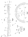
- FIG. 1 illustrated first embodiment of a sliding bearing shell 10 1 according to the invention is shown in the unwound, planar state with reference to a sectional view.
- a bending step takes place, with which the flat plain bearing shell 10 1 is bent, so that it forms a half shell, which covers an angle of about 180 ° (see. FIG. 7 ).
- Two sliding bearing shells 10 1 form a complete bearing, wherein the two plain bearing shells do not necessarily have to be identical.
- FIG. 2 is the first embodiment of the sliding bearing shell 10 1 shown with reference to a perspective view. It is already bent and thus can already be used with a second plain bearing shell for supporting a shaft, not shown.
- the sliding bearing shell 10 1 comprises a distributor groove 12 which extends on an inner side 14 of the sliding bearing shell 10 1 in the circumferential direction of the sliding bearing shell 10 1 . To define the circumferential direction, this is in FIG. 3 marked with the line X. The largest extension of the distributor groove 12 should extend in the circumferential direction.
- an oil hole 16 is provided, which passes through the plain bearing shell 10 1 radially and through which oil can be conveyed or injected into the distributor groove 12 by means of an oil pump, not shown.
- the plain bearing shell 10 1 has a collecting groove 18, which also extends on the inner side 14 and in the circumferential direction of the sliding bearing shell 10 1 .
- the relevant comments on the extension of the distributor groove 12 apply to the collecting groove 18 accordingly.
- the collecting groove 18 is closed all around and surrounded by a support surface 20.
- a support surface 20 As a support surface 20 is used Each surface of the inner side 14 of the sliding bearing shell 10 1 , on which an oil film for supporting and sliding of a shaft, not shown, can form.
- the direction of rotation of the shaft is shown by the arrow V. It can thus be seen that the collecting groove 18 is arranged in the direction of rotation of the shaft in front of the distributor groove 12.
- FIG. 3 a second embodiment 10 2 of the sliding bearing shell according to the invention is illustrated with reference to a plan view, which differs substantially from the dimensions of the first embodiment.
- the plain bearing shell 10 2 has a total width b ges and an overall height h ges (see. FIG. 4 ) on.
- the distributor groove 12 has a first distance A 1 from a first circumferential end 22 and the collecting groove 18 has a second distance A 2 from a second circumferential end 24 of the sliding bearing shell 10 1 .
- the distributor groove 12 and the collecting groove 18 have a third distance A 3 between their respective mutually facing ends and are thus arranged one behind the other in the circumferential direction.
- the support surface 20 is shown hatched, which surrounds the distribution groove 12 and collecting groove 18 around.
- the oil hole 16 1 configured as a slot.
- the distributor groove 12 has a first length l 1 , a first width b 1 and a first depth t 1 and the collecting groove 18 has a second length l 2 , a second width b 2 and a second depth t 2 .
- the depths are to indicate the maximum distance between the distribution groove 12 and the collecting groove 18 surrounding the support surface 20 and a groove bottom 28.
- the distributor groove 12 and the collecting groove 18 have identical dimensions, so that the lengths l 1 and l 2 , the widths b 1 and b 2 and the depths t 1 , t 2 are the same.
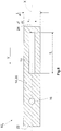
- FIG. 4 shows the distributor groove 12 and the collecting groove 18 in the circumferential direction with a first radius r 1 'from the support surface 20 in a relative to the support surface 20 inclined portion 26 via.
- the inclined portion 26 also merges with the first radius r 1 "into the groove bottom 28 of the distributor groove 12 and the collecting groove 18.
- the first radii r 1 ', r 1 " may be identical or different.
- the distributor groove 12 and / or the collecting groove 18 can be manufactured without the first radius r 1 .
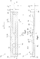
- FIG. 6 is the plain bearing shell 10 2 according to the second embodiment along in FIG. 3 defined sectional plane BB shown.
- the collecting groove 18 is perpendicular to the circumferential direction with a third radius r 3 in the support surface 20 via.
- the collecting groove 18 abuts perpendicular to the groove bottom 28, wherein here is a transition with the third radius r 3 or another radius is conceivable.
- other transitions for example as a chamfer, can be provided.
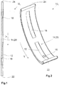
- FIG. 5 is a second embodiment of the sliding bearing shell 10 3 according to the invention analogous to in FIG. 1 shown selected representation.
- the structure of the third embodiment differs from the first essentially in that the distributor groove 12 and the collecting groove 18 in the circumferential direction have a circular segment-shaped profile profile with a second radius r 2 .
- the profile profiles of the distributor groove 12 and the collecting groove 18 are identical, so that the lengths in and l 2 are the same.
- FIG. 7 is the sliding bearing shell 10 3 shown in the third embodiment in the rolled and thus installable state in which it sweeps an angle of about 180 ° between the first circumferential end 22 and the second circumferential end 24. It can further be seen that, in the rolled state, the distributor groove 12 extends at a first angle ⁇ and the collecting groove 18 at a second angle ⁇ in the circumferential direction, so that the angular dimensions refer exclusively to the rolled state of the sliding bearing shell 10 3 shown here.
- the angle corresponds to the angle enclosed by two normals N emanating from the respective ends of the distributor groove 12 and the collecting groove 18 and lying in the same cutting plane.
- These are the normal N 11 to N 22 , wherein the angular size of the distributor groove 12 of the normals N 11 and N 12 and that of the collecting groove 18 of the normals N 21 and N 22 is described.
- the distribution groove 12 and the collecting groove 18 terminate at the point where they pass into the support surface 20. Since the lengths l 1 , l 2 of the collecting groove 12 and the distributor groove 18 are equal (see. FIG. 5 ), are also the first and second angle ⁇ , ⁇ equal, although other dimensions can be provided here.
- FIG. 8 is a non-inventive plain bearing shell 10 4 illustrated by a plan view in the unwound, flat state.
- This plain bearing shell 10 4 has no distribution groove. Instead, the oil hole 16 goes directly into the wing 20.
- FIG. 9 is a final embodiment of the sliding bearing shell 10 5 according to the invention shown in a developed plan view in the unwound.
- the plain bearing shell 10 5 comprises a plurality of collecting grooves, in this case three collecting grooves 18 1 to 18 3 , each having different lengths l 21 to l 23 and different widths b 2 to b 23 .
- the collecting grooves 18 are arranged in front of the oil hole 16 or the distributor groove 12 with respect to the direction of rotation of the shaft, which is indicated by the arrows V. This has the effect that the oil collected in the collecting groove 18 due to the rotation and the associated Towing action of the shaft of the oil hole 16 or the distributor groove 12 is supplied.
- the volume of the fresh oil can be reduced by the volume of oil collected in the collecting groove 18, so that the total required oil volume can be reduced.
- the oil pump must deliver a smaller volume flow, so that it requires less power, resulting in a fuel economy of the driving motor.
- the CO 2 balance is improved accordingly.
Description
Die vorliegende Erfindung betrifft eine Gleitlagerschale mit einer die Gleitlagerschale radial durchsetzenden Ölbohrung zum Einbringen von Öl in die Gleitlagerschale. Typische Anwendungen der gattungsgemäßen Gleitlagerschale sind das Kurbelwellenhauptlager oder das Pleuellager in Verbrennungsmotoren. Gleitlagerschalen der gattungsgemäßen Art sind beispielsweise aus der
Neben der Funktion der Ausbildung des Ölfilms dient das Öl der Kühlung des Gleitlagers, indem es die beim Betrieb entstehende Wärme aus dem Gleitlager ableitet. Die im Betrieb herrschenden Temperaturen liegen zwischen 90°C bei normalen Anwendungen bis 210°C bei extremen Anwendungen wie etwa bei Rennwagen. Etwa ¾ der Ölmenge, die in die Gleitlagerschale eingespritzt wird, dient zur Kühlung.In addition to the function of the formation of the oil film, the oil is used to cool the plain bearing by dissipating the heat generated during operation from the plain bearing. The operating temperatures range from 90 ° C in normal applications to 210 ° C in extreme applications such as racing cars. About ¾ of the amount of oil that is injected into the plain bearing shell is used for cooling.
Das Öl wird mittels einer Ölpumpe in die Gleitlagerschale eingespritzt. Die Ölpumpe wird von einem Motor angetrieben, der das Fahrzeug antreibt. Ein Teil der Leistung, die der Motor abgibt, wird zum Antreiben der Ölpumpe benötigt. Der Anteil der Leistung, die zum Antreiben der Ölpumpe benötigt wird, kann dadurch reduziert werden, dass der Volumenstrom des Öls durch die Ölbohrung gesenkt wird. Mit einer Reduzierung des Anteils der Leistung, die zum Antreiben der Ölpumpe benötigt wird, reduzieren sich auch der Kraftstoffverbrauch und damit auch die CO2-Emission des Motors.The oil is injected by means of an oil pump in the plain bearing shell. The oil pump is driven by a motor that drives the vehicle. Part of the power output by the engine is needed to drive the oil pump. The amount of power needed to drive the oil pump can be reduced by lowering the volume flow of oil through the oil well. Reducing the amount of power needed to drive the oil pump also reduces fuel consumption and hence engine CO 2 emissions.
Einige Gleitlagerschalen weisen Ölnuten auf, mit denen das Öl innerhalb der Gleitlagerschale verteilt wird. Der Volumenstrom ist proportional zur Oberfläche der Ölnut, weshalb man aus den zuvor genannten Gründen bestrebt ist, die Ölnut so gering wie möglich zu gestalten. Die Gleitlagerschale umschließt üblicherweise einen Winkel von 180° in Umfangsrichtung, so dass zwei Gleitlagerschalen die zu lagernde Welle vollständig umfassen. Die Ölnut kann dabei die gesamte Gleitlagerschale durchlaufen, so dass sie sich ebenfalls über einen Winkel von 180° in Umfangsrichtung erstreckt. Um die Oberfläche der Ölnut und damit den Volumenstrom des Öls durch die Ölnut zu reduzieren, kann der Winkel gesenkt werden. Es sind Gleitlager bekannt, deren Ölnut in Umfangsrichtung vor den Teilflächen der Gleitlagerschale ausläuft, vgl.
Mit sich verringerndem Winkel der Ölnut muss die benötigte Menge an Öl über eine geringere Oberfläche in das Gleitlager eingebracht und das Öl über eine größere Fläche verteilt werden, um eine einwandfreie Lagerung zu gewährleisten. Dies führt dazu, dass ein steigender Anteil des Öls seitlich aus dem Gleitlager austritt und ungenutzt verloren geht. Üblicherweise wird eine deutlich größere Menge an Öl in das Gleitlager eingebracht als tatsächlich notwendig, um die einwandfreie Lagerung der Welle zu gewährleisten und einen Ausfall zu vermeiden. Um den hierzu notwendigen Volumenstrom aufzubringen, muss der Motor eine höhere Leistung an die Ölpumpe abgeben, weshalb der Verbrauch des Motors steigt.As the oil groove angle decreases, the required amount of oil must be introduced into the sleeve bearing via a smaller surface area and the oil spread over a larger area to ensure proper bearing. This causes an increasing portion of the oil laterally from the plain bearing exit and get lost. Usually, a significantly larger amount of oil is introduced into the sliding bearing as actually necessary to ensure proper storage of the shaft and to avoid failure. In order to apply the volume flow required for this purpose, the engine must deliver a higher power to the oil pump, which is why the consumption of the engine increases.
Andere Gleitlagerschalen weisen aus unterschiedlichen Gründen zusätzlich zur Ölnut seitlich von dieser angeordnete Rillen oder separate, parallele Schlitze auf, vgl.
In der
Aufgabe der vorliegenden Erfindung ist es, die oben diskutierten Nachteile der gattungsgemäßen Gleitlager zumindest zu reduzieren und eine Gleitlagerschale anzugeben, mit welcher das in der Gleitlagerschale befindliche Öl besser genutzt werden kann, so dass der für die Ölpumpe benötigte Anteil der Leistung des Motors und gleichzeitig der seitliche Austritt aus dem Gleitlager reduziert werden kann.Object of the present invention is to reduce the above-discussed disadvantages of the generic plain bearing at least and specify a plain bearing shell, with which the oil contained in the plain bearing shell can be better used, so that required for the oil pump portion of the power of the engine and at the same time lateral exit from the sliding bearing can be reduced.
Gelöst wird die Aufgabe durch eine Gleitlagerfläche gemäß Anspruch 1. Unter geschlossener Sammelnut soll eine Nut verstanden werden, in die keine Ölbohrung mündet. Die geschlossene Sammelnut bewirkt innerhalb des Ölfilms eine Querschnittserweiterung, weshalb dem Öl im Bereich der Sammelnut ein größeres geschlossenes Volumen zur Verfügung steht, so dass in der Sammelnut ein Unterdruck erzeugt wird. Folglich bildet sich im Bereich der Sammelnut, wo der Unterdruck anliegt, eine Saugwirkung aus, so dass Öl in diesen Bereich der Sammelnut gesaugt wird und sich eine zur Sammelnut hin gerichtete Strömung im Ölfilm ausbildet. Die Menge an Öl, die seitlich aus dem Gleitlager austritt, wird somit verringert und das Öl erneut genutzt, so dass auch der von der Ölpumpe zu fördernde Volumenstrom an Öl in die Gleitlagerschale reduziert werden kann. Erfindungsgemäß ist die Sammelnut in Drehrichtung der zu lagernden Welle vor der Ölbohrung angeordnet, so dass das gesammelte Öl direkt mit dem frischen, durch die Ölnut hindurchtretenden Öl gemischt und zusammen zum Aufbau des Ölfilms verwendet werden kann. Als Konsequenz reduziert sich der Anteil der Leistung, die der Motor zum Antreiben der Ölpumpe aufbringen muss, wodurch der Verbrauch des Motors und damit seine CO2-Emission gesenkt werden. Vorzugsweise wird die erfindungsgemäße Gleitlagerschale im Kurbelwellenhauptlager eingesetzt. Die Ölbohrung kann einen kreisförmigen Querschnitt haben und mit einem Bohrer gefertigt werden oder aber auch einen elliptischen Querschnitt haben oder ein Langloch sein und gefräst werden.The problem is solved by a sliding bearing surface according to claim 1. Under closed collecting groove is to be understood a groove into which no oil hole opens. The closed collecting groove causes a cross-sectional widening within the oil film, so that the oil in the region of the collecting groove, a larger closed volume is available, so that in the collecting groove, a negative pressure is generated. Consequently, in the region of the collecting groove, where the negative pressure is applied, forms a suction effect, so that oil is sucked into this region of the collecting groove and forms a Sammelnut towards directed flow in the oil film. The amount of oil exiting laterally from the plain bearing is thus reduced and the oil is reused, so that the volume flow of oil to be delivered by the oil pump into the plain bearing shell can also be reduced. According to the collecting groove is arranged in the direction of rotation of the shaft to be stored in front of the oil hole, so that the collected oil can be mixed directly with the fresh, passing through the oil groove oil and used together to build the oil film. As a consequence, the amount of power that the engine must drive to drive the oil pump reduces, thereby reducing the consumption of the engine and thus its CO 2 emissions. The sliding bearing shell according to the invention is preferably used in the crankshaft main bearing. The oil hole may have a circular cross-section and be made with a drill or even have an elliptical cross-section or be a slot and be milled.
Aufgrund der sich auf einer Innenseite der Gleitlagerschale im Wesentlichen in Umfangsrichtung der Gleitlagerschale erstreckenden Verteilernut wird die Verteilung des Öls innerhalb der Gleitlagerschale verbessert, so dass sich überall in der Gleitlagerschale ein gleichmäßiger Ölfilm zum Tragen der Welle ausbilden kann. In diesem Fall ist die Sammelnut in Drehrichtung der Welle vor dieser Verteilernut angeordnet. Weiterhin hat sich herausgestellt, dass bei einem Längen-zu-Breiten-Verhältniss von 10:1 bis 40:1 der Volumenstrom des in das Gleitlager eingebrachten Öls und damit auch der Kraftstoffverbrauch des Motors besonders stark reduziert werden kann.
Vorzugsweise endet die Verteilernut in Umfangsrichtung mit einem ersten Abstand vor einem ersten umfänglichen Ende der Gleitlagerschale. Die Tragfläche und damit die Tragfähigkeit der Gleitlagerschale werden somit vergrößert, wodurch größere Lasten aufgenommen werden können.Due to the distribution groove extending on an inner side of the sliding bearing shell substantially in the circumferential direction of the sliding bearing shell, the distribution of the oil within the sliding bearing shell is improved, so that a uniform oil film for supporting the shaft can be formed anywhere in the sliding bearing shell. In this case, the collecting groove in the direction of rotation of the shaft before this Distributor groove arranged. Furthermore, it has been found that with a length-to-width ratio of 10: 1 to 40: 1, the volume flow of the introduced into the plain bearing oil and thus the fuel consumption of the engine can be particularly reduced.
Preferably, the distribution groove terminates in the circumferential direction at a first distance in front of a first circumferential end of the sliding bearing shell. The wing and thus the bearing capacity of the plain bearing shell are thus increased, whereby larger loads can be absorbed.
In einer bevorzugten Ausgestaltung der erfindungsgemäßen Gleitlagerschale endet die Sammelnut in Umfangsrichtung mit einem zweiten Abstand vor einem zweiten umfänglichen Ende der Gleitlagerschale. Auch hierdurch können die Tragfläche und die Tragfähigkeit weiter vergrößert werden, so dass größere Lasten aufgenommen werden können.In a preferred embodiment of the sliding bearing shell according to the invention, the collecting groove ends in the circumferential direction with a second distance in front of a second circumferential end of the sliding bearing shell. This also allows the wing and the load capacity can be further increased, so that larger loads can be absorbed.
In einer favorisierten Weiterbildung erstrecken sich die Verteilernut mit einem ersten Winkelmaß zwischen 50° und 100° und die Sammelnut mit einem zweiten Winkelmaß zwischen 40° und 80° in Umfangsrichtung. Dabei muss das Winkelmaß jedoch so gewählt werden, dass immer ein bestimmter Abstand zwischen der Verteilernut und der Sammelnut verbleibt. Es hat sich herausgestellt, dass in diesem Bereich des ersten und zweiten Winkelmaßes der Volumenstrom des in das Gleitlager eingebrachten Öls und damit auch der Kraftstoffverbrauch des Motors besonders stark reduziert werden kann.In a preferred development, the distributor groove extend with a first angle between 50 ° and 100 ° and the collecting groove with a second angle between 40 ° and 80 ° in the circumferential direction. However, the angle must be chosen so that always a certain distance between the distributor groove and the collecting groove remains. It has been found that in this region of the first and second angular extent of the volume flow of the introduced into the plain bearing oil and thus the fuel consumption of the engine can be particularly reduced.
Vorzugsweise sind die erste und die Sammelnut im Wesentlichen gleich lang. Dies vereinfacht die Fertigung, da die erste und die Sammelnut mit einem identischen Arbeitsschritt gefertigt werden können. Allein die Position der Gleitlagerschale muss verändert werden, wodurch die Gleitlagerschale besonders günstig herstellbar ist.Preferably, the first and collecting grooves are substantially the same length. This simplifies the production, since the first and the collecting groove can be manufactured with an identical step. Only the position of the sliding bearing shell must be changed, whereby the plain bearing shell is particularly low to produce.
Vorzugsweise geht zumindest die Sammelnut in Umfangsrichtung mit einem ersten Radius in die Tragfläche oder einem Nutgrund über. Wie oben dargelegt, bildet sich in der Sammelnut ein geringerer Druck im Ölfilm aus, wodurch es zu ein Saugeffekt in der Sammelnut erzeugt wird. Da in dieser Ausbildung die Sammelnut mit einem ersten Radius in die Tragfläche übergeht, entstehen keine oder zumindest weniger Verwirbelungen, welche den Saugeffekt und die Strömung in die Sammelnut stören könnten. Werden sowohl die erste als auch die Sammelnut entsprechend mit einem kreissegmentförmigen Querschnitt gefertigt, wird die Fertigung weiter vereinfacht. Auch der Übergang in den Nutgrund mittels des ersten Radius reduziert die Verwirbelung innerhalb des Ölfilms, so dass sich der Saugeffekt besser entfalten kann.Preferably, at least the collecting groove in the circumferential direction with a first radius in the support surface or a groove bottom. As stated above, a lesser pressure in the oil film is formed in the collecting groove, thereby creating a suction effect in the collecting groove. Since in this embodiment, the collecting groove merges with a first radius in the support surface, no or at least less turbulence, which could disturb the suction effect and the flow in the collecting groove. If both the first and the collecting groove are manufactured in accordance with a circular segment-shaped cross section, the production is further simplified. Also, the transition into the groove bottom by means of the first radius reduces the turbulence within the oil film, so that the suction effect can develop better.
Es hat sich ebenfalls als besonders vorteilhaft für die Reduzierung des Volumenstroms des in das Gleitlager eingebrachten Öls und des Kraftstoffverbrauchs des Motors herausgestellt, wenn die erste und die Sammelnut jeweils ein Breiten-zu-Tiefen-Verhältnis von 10:1 bis 40:1 aufweisen.It has also been found to be particularly advantageous for reducing the volume flow of oil introduced into the sleeve bearing and the fuel consumption of the engine when the first and the collecting groove each have a width to depth ratio of 10: 1 to 40: 1.
Vorzugsweise geht zumindest die Sammelnut in Umfangsrichtung mit einem ersten Radius in die Tragfläche oder einem Nutgrund über. Wie oben dargelegt, bildet sich in der Sammelnut ein geringerer Druck im Ölfilm aus, wodurch es zu ein Saugeffekt in der Sammelnut erzeugt wird. Da in dieser Ausbildung die Sammelnut mit einem ersten Radius in die Tragfläche übergeht, entstehen keine oder zumindest weniger Verwirbelungen, welche den Saugeffekt und die Strömung in die Sammelnut stören könnten. Werden sowohl die erste als auch die Sammelnut entsprechend mit einem kreissegmentförmigen Querschnitt gefertigt, wird die Fertigung weiter vereinfacht. Auch der Übergang in den Nutgrund mittels des ersten Radius reduziert die Verwirbelung innerhalb des Ölfilms, so dass sich der Saugeffekt besser entfalten kann.Preferably, at least the collecting groove in the circumferential direction with a first radius in the support surface or a groove bottom. As stated above, a lesser pressure in the oil film is formed in the collecting groove, thereby creating a suction effect in the collecting groove. Since in this embodiment, the collecting groove merges with a first radius in the support surface, no or at least less turbulence, which could disturb the suction effect and the flow in the collecting groove. If both the first and the collecting groove are manufactured in accordance with a circular segment-shaped cross section, the production is further simplified. Also, the transition into the groove bottom by means of the first radius reduces the turbulence within the oil film, so that the suction effect can develop better.
Vorteilhafterweise weist zumindest die Sammelnut in Umfangsrichtung im Wesentlichen kreissegmentförmigen Profilverlauf im Nutgrund mit einem zweiten Radius auf. Der Übergang von der Tragfläche in die Sammelnut entlang der Längsachse ist in dieser Ausbildung sehr sanft ausgestaltet, so dass keine oder zumindest weniger Verwirbelungen im Ölfilm generiert werden, welche den Saugeffekt und die Strömung in die Sammelnut stören könnten. Weiterhin ist die Fertigung der Sammelnut in dieser Ausbildung sehr einfach, da das entsprechende spanabhebende Werkzeug nur gedreht und nicht lateral verschoben werden muss. Die Nuten können beispielsweise mittels eines drehenden Fräskopfes gefertigt werden, der mit seiner Umfangsfläche das Material abträgt. Werden sowohl die Verteilernut als auch die Sammelnut entsprechend mit einem kreissegmentförmigen Querschnitt gefertigt, wird die Fertigung weiter vereinfacht. Die Verwendung "im Wesentlichen kreisförmig" wird deshalb verwendet, dass zum einen ein streng kreisförmiger Profilverlauf aufgrund der üblichen Fertigungsungenauigkeiten nicht herstellbar ist. Zum anderen ist es denkbar, die Ölnuten vor dem Biegen, also im ebenen Zustand der Gleitlagerschale zu fertigen. Ein im ebenen Zustand kreissegmentförmiger Profilverlauf im Nutgrund würde durch das Rollen geometrisch verändert werden und nicht mehr streng kreissegmentförmig verlaufen. Insofern sollen alle Formen, die ausschließlich durch Drehen des spanabhebenden Werkzeugs um eine relativ zur Gleitlagerschale in ihrer Position unveränderliche Achse mit dem Merkmal "in Umfangsrichtung im Wesentlichen kreissegmentförmiger Profilverlauf" umfasst sein.Advantageously, at least the collecting groove in the circumferential direction has a substantially circular segment-shaped profile course in the groove base with a second radius. The transition from the support surface into the collecting groove along the longitudinal axis is designed very gently in this embodiment, so that no or at least less turbulence in the oil film are generated, which could disturb the suction effect and the flow into the collecting groove. Furthermore, the production of the collecting groove in this embodiment is very simple, since the corresponding cutting tool only has to be rotated and not moved laterally. The grooves can be made for example by means of a rotating milling head, which removes the material with its peripheral surface. If both the distributor groove and the collecting groove are manufactured in accordance with a circular segment-shaped cross-section, the production is further simplified. The use of "substantially circular" is therefore used that on the one hand a strictly circular profile profile due to the usual manufacturing inaccuracies can not be produced. On the other hand, it is conceivable to manufacture the oil grooves before bending, ie in the flat state of the sliding bearing shell. A profile shape in the groove base which is in the form of a circle segment in the planar state would be changed geometrically by the rolling and would no longer be strictly circular-segment-shaped. In this respect, all forms that are exclusively by turning the cutting tool to a relative to the plain bearing shell in its position invariable axis with the feature "circumferentially substantially circular segment-shaped profile course" to be encompassed.
Bevorzugt geht zumindest die Sammelnut senkrecht zur Umfangsrichtung mit einem dritten Radius in die Tragfläche über. Auch hierdurch werden die Verwirbelungen zumindest reduziert, so dass der Saugeffekt und die Strömung des Öls in die Sammelnut nicht oder weniger stark gestört werden.Preferably, at least the collection groove transitions perpendicular to the circumferential direction with a third radius in the support surface. As a result, the turbulences are at least reduced, so that the suction effect and the flow of the oil are not or less disturbed in the collecting groove.
Bevorzugt weisen die Verteilernut und die Sammelnut gleiche Profilverläufe in Umfangsrichtung und/oder senkrecht zur Umfangsrichtung auf. Hierdurch wird die Fertigung der Gleitlagerschale vereinfacht, da zur Herstellung der ersten und der zweiten Nut dasselbe Werkzeug verwendet werden kann. Das Umrüsten des Werkzeughalters oder das Vorsehen eines zweiten Werkzeughalters können entfallen.Preferably, the distributor groove and the collecting groove have the same profile profiles in the circumferential direction and / or perpendicular to the circumferential direction. As a result, the production of the plain bearing shell is simplified because the same tool can be used to produce the first and the second groove. The conversion of the tool holder or the provision of a second tool holder can be omitted.
Eine Weiterbildung der erfindungsgemäßen Gleitlagerschale zeichnet sich dadurch aus, dass die Verteilernut und Sammelnut mittels eines Kanals verbunden sind. Dieser Kanal weist vorzugsweise einen deutlich kleineren Querschnitt als die Verteilernut und die Sammelnut auf, so dass der Saugeffekt nur unwesentlich beeinträchtigt wird. Im Kanal kann sich Öl sammeln, welches bei Bedarf zur Verfügung steht. Durch die Drehbewegung der Welle wird das im Kanal gesammelte Öl mitgeschleppt und bildet einen Ölkeil, mit dem die Tragfähigkeit des Gleitlagers erhöht werden kann.A development of the sliding bearing shell according to the invention is characterized in that the distributor groove and collecting groove are connected by means of a channel. This channel preferably has a significantly smaller cross section than the distributor groove and the collecting groove, so that the suction effect is only insignificantly impaired. In the channel can collect oil, which is available when needed. The rotational movement of the shaft entrains the oil collected in the channel and forms an oil wedge, which can increase the bearing capacity of the plain bearing.
Die Erfindung wird im Folgenden unter Bezugnahme auf die anhängenden Zeichnungen anhand von bevorzugten Ausführungsbeispielen im Detail erläutert. Es zeigen
- Figur 1
- ein erstes Ausführungsbeispiel einer erfindungsgemäßen Gleitlagerschale im abgewickelten Zustand,
Figur 2- das in
Figur 1 gezeigte Ausführungsbeispiel in einer perspektivischen Darstellung, Figur 3- ein zweites Ausführungsbeispiel der erfindungsgemäßen Gleitlagerschale anhand einer Draufsicht im abgewickelten Zustand,
- Figur 4
- eine Schnittdarstellung des in
Figur 3Figur 3 - Figur 5
- ein drittes Ausführungsbeispiel der erfindungsgemäßen Gleitlagerschale anhand einer Schnittdarstellung analog zu in
Figur 4 verwendeten Darstellung im abgewickelten Zustand, - Figur 6
- eine Schnittdarstellung des zweiten Ausführungsbeispiels entlang der in
Figur 3 - Figur 7
- das in
Figur 5 gezeigte dritte Ausführungsbeispiel im gerollten Zustand, - Figur 8
- eine nicht erfindungsgemäße Gleitlagerschale anhand einer Draufsicht im abgewickelten Zustand, und
- Figur 9
- ein letztes Ausführungsbeispiel der erfindungsgemäßen Gleitlagerschale anhand einer Draufsicht im abgewickelten Zustand.
- FIG. 1
- a first embodiment of a sliding bearing shell according to the invention in the developed state,
- FIG. 2
- this in
FIG. 1 embodiment shown in a perspective view, - FIG. 3
- A second embodiment of the sliding bearing shell according to the invention with reference to a plan view in the developed state,
- FIG. 4
- a sectional view of the in
FIG. 3 illustrated embodiment along inFIG. 3 defined cutting plane AA, - FIG. 5
- a third embodiment of the sliding bearing shell according to the invention with reference to a sectional view analogous to in
FIG. 4 used representation in the unwound state, - FIG. 6
- a sectional view of the second embodiment along in in
FIG. 3 defined section plane BB, - FIG. 7
- this in
FIG. 5 shown third embodiment in the rolled state, - FIG. 8
- a non-inventive sliding bearing shell based on a plan view in the developed state, and
- FIG. 9
- a final embodiment of the sliding bearing shell according to the invention with reference to a plan view in the unwound state.
Das in
In
Die Gleitlagerschale 101 umfasst eine Verteilernut 12, die sich auf einer Innenseite 14 der Gleitlagerschale 101 in Umfangsrichtung der Gleitlagerschale 101 erstreckt. Zur Definition der Umfangsrichtung ist diese in
Weiterhin weist die Gleitlagerschale 101 eine Sammelnut 18 auf, welche sich ebenfalls auf der Innenseite 14 und in Umfangsrichtung der Gleitlagerschale 101 erstreckt. Die diesbezüglichen Ausführungen zur Erstreckung der Verteilernut 12 gelten für die Sammelnut 18 entsprechend. Die Sammelnut 18 ist ringsum geschlossen und von einer Tragfläche 20 umgeben. Als Tragfläche 20 dient jede Fläche der Innenseite 14 der Gleitlagerschale 101, auf der sich ein Ölfilm zum Lagern und Gleiten einer nicht dargestellten Welle ausbilden kann. Die Drehrichtung der Welle ist mit dem Pfeil V dargestellt. Es ist somit ersichtlich, dass die Sammelnut 18 in Drehrichtung der Welle gesehen vor der Verteilernut 12 angeordnet ist.Furthermore, the plain bearing shell 10 1 has a collecting
In
Die Verteilernut 12 weist eine erste Länge l1, eine erste Breite b1 sowie eine erste Tiefe t1 und die Sammelnut 18 weist eine zweite Länge l2, eine zweite Breite b2 sowie eine zweite Tiefe t2 auf. Die Tiefen sollen dabei den maximalen Abstand zwischen der die Verteilernut 12 und die Sammelnut 18 umgebenden Tragfläche 20 und einem Nutgrund 28 angeben. Gemäß dem zweiten Ausführungsbeispiel besitzen die Verteilernut 12 und die Sammelnut 18 identische Abmessungen, so dass die Längen l1 und l2, die Breiten b1 und b2 sowie die Tiefen t1, t2 jeweils gleich sind.The
Wie aus
In
In
In
Das Winkelmaß entspricht dem Winkel, der von zwei Normalen N eingeschlossen wird, die von den jeweiligen Enden der Verteilernut 12 und der Sammelnut 18 ausgehen und in derselben Schnittebene liegen. In
In
In
In allen Ausführungsbeispielen sind die Sammelnuten 18 bezogen auf die Drehrichtung der Welle, die mit den Pfeilen V gekennzeichnet ist, vor der Ölbohrung 16 bzw. der Verteilernut 12 angeordnet. Dies hat den Effekt, dass das in der Sammelnut 18 gesammelte Öl infolge der Drehung und der damit verbundenen Schleppwirkung der Welle der Ölbohrung 16 oder der Verteilernut 12 zugeführt wird. Insofern wird das bereits in der Gleitlagerschale 10 befindliche Öl mit frischem Öl, welches durch die Ölbohrung in die Gleitlagerschale 10 eingebracht wird, zusammengebracht und kann wiederverwendet werden. Das Volumen des frischen Öls kann um das Volumen des in der Sammelnut 18 gesammelten Öls verringert werden, so dass das insgesamt benötigte Ölvolumen verringert werden kann. Infolgedessen muss die Ölpumpe einen geringeren Volumenstrom fördern, so dass sie weniger Leistung benötigt, was zu einer Kraftstoffersparnis des antreibenden Motors führt. Die CO2-Bilanz wird entsprechend verbessert.In all embodiments, the collecting
- 101 - 105 10 1 - 10 5
- Gleitlagerschaleplain bearing shell
- 1212
- Verteilernutdistributor
- 1414
- Innenseiteinside
- 16, 161 16, 16 1
- Ölbohrungoil well
- 1818
- Sammelnutcollecting groove
- 2020
- Tragflächewing
- 2222
- erstes umfängliches Endefirst circumferential end
- 2424
- zweites umfängliches Endesecond circumferential end
- 2626
- geneigter Abschnittinclined section
- 2828
- Nutgrundgroove base
- A1 - A3 A 1 - A 3
- Abstanddistance
- b1 b 1
- Breite VerteilernutWide distribution groove
- b2 b 2
- Breite SammelnutWide collecting groove
- bges b ges
- Breite GleitlagerschaleWide plain bearing shell
- hges h sat
- Höhe GleitlagerschaleHeight of plain bearing shell
- l1 1
- Länge VerteilernutLength distribution groove
- l2 l 2
- Länge SammelnutLength collecting groove
- N11 - N22 N 11 - N 22
- Normalennormal
- r1 - r3 r 1 - r 3
- Radienradii
- t1 t 1
- Tiefe VerteilernutDeep distribution groove
- t2 t 2
- Tiefe SammelnutDeep collecting groove
- XX
- Linie, welche die Umfangsrichtung definiertLine defining the circumferential direction
- αα
- erstes Winkelmaßfirst angle measure
- ββ
- zweites Winkelmaßsecond angle measure
Claims (10)
- Plain bearing shell in the shape of a half shell, which covers an angle of approximately 180°, comprising
an oil hole (16) which radially passes through the plain bearing shell and is intended for introducing oil into the plain bearing shell,
and comprising a distribution groove (12) which extends on an inner side (14) of the plain bearing shell (10) substantially in the peripheral direction of the plain bearing shell (10) and is intended for distributing the oil that has been introduced within the plain bearing shell, the oil hole (16) leading into the distribution groove (12),
the plain bearing shell comprising one or more collection grooves (18) which extend on the inner side (14) of the plain bearing shell (10) in the peripheral direction and are intended for collecting the oil that is inside the plain bearing shell, the one or more collection grooves (18) being closed and peripherally surrounded by a bearing surface (20),
the distribution groove (12) and the one or more collection grooves (18) being arranged one behind the other in the peripheral direction,
characterised in that the distribution groove (12) and the one or more collection grooves (18) each have a length-to-width ratio of from 10:1 to 40:1. - Plain bearing shell according to claim 1, characterised in that the distribution groove (12) ends in the peripheral direction at a first distance (A1) from a first peripheral end (22) of the plain bearing shell (10).
- Plain bearing shell according to any one of the preceding claims, characterised in that the collection groove (18) ends in the peripheral direction at a second distance (A2) from a second peripheral end (24) of the plain bearing shell (10).
- Plain bearing shell according to any one of the preceding claims, characterised in that the distribution groove (12) extends in the peripheral direction at a first angle (α) of between 50° and 100°, and the collection groove (18) extends in the peripheral direction at a second angle (β) of between 40° and 80°.
- Plain bearing shell according to any one of the preceding claims, characterised in that the distribution groove (12) and the collection groove (18) are of substantially the same length.
- Plain bearing shell according to any one of the preceding claims, characterised in that the distribution groove (12) and the collection groove (18) each have a width-to-depth ratio of from 10:1 to 40:1.
- Plain bearing shell according to any one of the preceding claims, characterised in that at least the collection groove (18) transitions into the bearing surface (20) and/or into a groove base (28) in the peripheral direction at a first radius (r1).
- Plain bearing shell according to any one of the preceding claims, characterised in that at least the collection groove (18) has a profile curve that is substantially in the shape of a circular segment on the groove base (28) in the peripheral direction at a second radius (r2).
- Plain bearing shell according to any one of the preceding claims, characterised in that at least the collection groove (18) transitions into the bearing surface (20) perpendicularly to the peripheral direction at a third radius (r3).
- Plain bearing shell according to any one of the preceding claims, characterised in that the distribution groove (12) and the collection groove (18) have identical profile curves in the peripheral direction and/or perpendicularly to the peripheral direction.
Applications Claiming Priority (2)
| Application Number | Priority Date | Filing Date | Title |
|---|---|---|---|
| DE102011005467.7A DE102011005467B4 (en) | 2011-03-11 | 2011-03-11 | Plain bearing shell with a collecting groove |
| PCT/EP2012/052664 WO2012123213A1 (en) | 2011-03-11 | 2012-02-16 | Sliding bearing shell comprising a collecting groove |
Publications (2)
| Publication Number | Publication Date |
|---|---|
| EP2683956A1 EP2683956A1 (en) | 2014-01-15 |
| EP2683956B1 true EP2683956B1 (en) | 2017-11-22 |
Family
ID=45592411
Family Applications (1)
| Application Number | Title | Priority Date | Filing Date |
|---|---|---|---|
| EP12703842.0A Not-in-force EP2683956B1 (en) | 2011-03-11 | 2012-02-16 | Sliding bearing shell comprising a collecting groove |
Country Status (8)
| Country | Link |
|---|---|
| US (1) | US8783954B2 (en) |
| EP (1) | EP2683956B1 (en) |
| JP (1) | JP5971869B2 (en) |
| KR (1) | KR101899620B1 (en) |
| CN (1) | CN103415714B (en) |
| BR (1) | BR112013022603A2 (en) |
| DE (1) | DE102011005467B4 (en) |
| WO (1) | WO2012123213A1 (en) |
Families Citing this family (17)
| Publication number | Priority date | Publication date | Assignee | Title |
|---|---|---|---|---|
| FR3002587B1 (en) * | 2013-02-25 | 2015-04-10 | Renault Sa | CRANKSHAFT TWIN CUSHIONS |
| JP5837896B2 (en) * | 2013-03-21 | 2015-12-24 | 大豊工業株式会社 | Plain bearing |
| JP2015001250A (en) * | 2013-06-14 | 2015-01-05 | 大同メタル工業株式会社 | Bearing device |
| JP2015001251A (en) * | 2013-06-14 | 2015-01-05 | 大同メタル工業株式会社 | Bearing device |
| GB2517978A (en) * | 2013-09-09 | 2015-03-11 | Mahle Int Gmbh | Bearing shell |
| DE102014200594A1 (en) * | 2014-01-15 | 2015-07-16 | Voith Patent Gmbh | Hydrodynamic plain bearing |
| CN105899829B (en) | 2014-01-15 | 2018-01-02 | 福伊特专利有限公司 | Hydrodynamic plain bearing |
| JP6314103B2 (en) * | 2015-02-27 | 2018-04-18 | 大豊工業株式会社 | Plain bearing |
| JP2017110764A (en) * | 2015-12-17 | 2017-06-22 | 大豊工業株式会社 | Slide bearing |
| JP2017110765A (en) * | 2015-12-17 | 2017-06-22 | 大豊工業株式会社 | Slide bearing |
| JP6923465B2 (en) * | 2018-02-09 | 2021-08-18 | 大同メタル工業株式会社 | Main bearing for crankshaft of internal combustion engine |
| AT521246B1 (en) * | 2018-07-10 | 2019-12-15 | Miba Gleitlager Austria Gmbh | plain bearing element |
| DE102018119504A1 (en) * | 2018-08-10 | 2020-02-13 | Schuler Pressen Gmbh | Process for manufacturing a plain bearing and plain bearing |
| JP7201720B2 (en) * | 2021-02-12 | 2023-01-10 | 大同メタル工業株式会社 | Half bearings and plain bearings |
| JP7201719B2 (en) * | 2021-02-12 | 2023-01-10 | 大同メタル工業株式会社 | Half bearings and plain bearings |
| CN113446307A (en) * | 2021-06-18 | 2021-09-28 | 东方电气集团东方汽轮机有限公司 | Radial sliding bearing with lower bush having partial circumferential groove |
| JP2023030707A (en) * | 2021-08-24 | 2023-03-08 | 大同メタル工業株式会社 | Half bearing and slide bearing |
Citations (3)
| Publication number | Priority date | Publication date | Assignee | Title |
|---|---|---|---|---|
| DE2847246A1 (en) * | 1978-10-31 | 1980-05-08 | May Michael G | Reciprocating engine bearing shell - has orifices and recesses in bearing surface to reduce friction |
| DE3825449A1 (en) * | 1987-11-23 | 1989-06-01 | Schwermasch Liebknecht Veb K | Radial sliding bearing |
| DE102009002772A1 (en) * | 2009-04-30 | 2010-11-04 | Federal-Mogul Wiesbaden Gmbh | Plain bearing shell for use in hydrodynamic sliding bearing for supporting counter-rotor, has grooves recycling lubricant to axial center of shell and aligned in axial boundary region toward center of shell |
Family Cites Families (25)
| Publication number | Priority date | Publication date | Assignee | Title |
|---|---|---|---|---|
| US1948340A (en) * | 1931-04-17 | 1934-02-20 | Gen Motors Corp | Groove for main bearings |
| US1940301A (en) * | 1931-10-23 | 1933-12-19 | Gen Electric | Shaft bearing |
| US2004254A (en) * | 1933-08-12 | 1935-06-11 | Gen Motors Corp | Crankshaft bearing |
| US2697017A (en) * | 1951-07-28 | 1954-12-14 | Gen Electric | Journal bearing |
| US2901297A (en) * | 1956-07-16 | 1959-08-25 | Gen Electric | Bearings |
| DE2305834C3 (en) * | 1973-02-07 | 1980-04-10 | Daimler-Benz Ag, 7000 Stuttgart | Device for lubricating a bearing for preferably rocker arms on motor vehicles |
| JPS52113445A (en) * | 1976-03-19 | 1977-09-22 | Daido Metal Co Ltd | Bearing metal |
| JPS5676117U (en) * | 1979-11-16 | 1981-06-22 | ||
| JPS58149622U (en) * | 1982-03-31 | 1983-10-07 | いすゞ自動車株式会社 | bearing device |
| DE3621577A1 (en) * | 1985-07-26 | 1987-02-05 | Glyco Metall Werke | Sliding bearing |
| US5009522A (en) * | 1990-04-02 | 1991-04-23 | General Motors Corporation | Reduced flow bearing |
| JP3554429B2 (en) * | 1996-02-06 | 2004-08-18 | 本田技研工業株式会社 | Rotary shaft lubrication structure |
| JP2000346045A (en) * | 1999-06-01 | 2000-12-12 | Daido Metal Co Ltd | Main shaft bearing for engine |
| JP3643272B2 (en) * | 1999-10-12 | 2005-04-27 | 大同メタル工業株式会社 | Plain bearing |
| JP3623737B2 (en) * | 2000-12-25 | 2005-02-23 | 大同メタル工業株式会社 | Half bearing |
| DE10105542A1 (en) * | 2001-02-07 | 2002-08-29 | Porsche Ag | Lube oil supply for the connecting rod bearings of a crankshaft of a multi-cylinder internal combustion engine |
| WO2004038188A1 (en) * | 2002-10-24 | 2004-05-06 | Taiho Kogyo Co., Ltd. | Oil-feeding device for engine crankshaft |
| JP2005249024A (en) * | 2004-03-03 | 2005-09-15 | Daido Metal Co Ltd | Slide bearing |
| JP2005256917A (en) * | 2004-03-11 | 2005-09-22 | Daido Metal Co Ltd | Sliding bearing |
| FR2878590B1 (en) * | 2004-11-29 | 2007-01-05 | Renault Sas | FRICTION REDUCTION OF A HYDRODYNAMIC BEARING |
| DE102005037502B4 (en) * | 2005-08-09 | 2009-11-26 | Federal-Mogul Wiesbaden Gmbh | bearing shell |
| DE102006010698B4 (en) * | 2006-03-08 | 2012-03-29 | Federal-Mogul Wiesbaden Gmbh | Bearing shell and bearing |
| FR2910087B1 (en) * | 2006-12-19 | 2009-01-23 | Renault Sas | INNER COMBUSTION ENGINE ROD FOOT |
| DE102008008584A1 (en) * | 2008-02-12 | 2009-08-13 | Bayerische Motoren Werke Aktiengesellschaft | Sliding bearing shell for split sliding bearing in internal combustion engine, has radially revolving processing cavities on inner surface, and lubricant slot running on side of shell and not before bevel of inner surface |
| JP4994294B2 (en) * | 2008-04-14 | 2012-08-08 | 大同メタル工業株式会社 | Slide bearing for internal combustion engine |
-
2011
- 2011-03-11 DE DE102011005467.7A patent/DE102011005467B4/en active Active
-
2012
- 2012-02-16 CN CN201280012726.6A patent/CN103415714B/en not_active Expired - Fee Related
- 2012-02-16 JP JP2013557031A patent/JP5971869B2/en not_active Expired - Fee Related
- 2012-02-16 US US14/004,505 patent/US8783954B2/en not_active Expired - Fee Related
- 2012-02-16 WO PCT/EP2012/052664 patent/WO2012123213A1/en active Application Filing
- 2012-02-16 KR KR1020137026770A patent/KR101899620B1/en active IP Right Grant
- 2012-02-16 EP EP12703842.0A patent/EP2683956B1/en not_active Not-in-force
- 2012-02-16 BR BR112013022603A patent/BR112013022603A2/en not_active Application Discontinuation
Patent Citations (3)
| Publication number | Priority date | Publication date | Assignee | Title |
|---|---|---|---|---|
| DE2847246A1 (en) * | 1978-10-31 | 1980-05-08 | May Michael G | Reciprocating engine bearing shell - has orifices and recesses in bearing surface to reduce friction |
| DE3825449A1 (en) * | 1987-11-23 | 1989-06-01 | Schwermasch Liebknecht Veb K | Radial sliding bearing |
| DE102009002772A1 (en) * | 2009-04-30 | 2010-11-04 | Federal-Mogul Wiesbaden Gmbh | Plain bearing shell for use in hydrodynamic sliding bearing for supporting counter-rotor, has grooves recycling lubricant to axial center of shell and aligned in axial boundary region toward center of shell |
Also Published As
| Publication number | Publication date |
|---|---|
| US20130343682A1 (en) | 2013-12-26 |
| WO2012123213A9 (en) | 2014-03-06 |
| CN103415714B (en) | 2016-10-19 |
| EP2683956A1 (en) | 2014-01-15 |
| DE102011005467B4 (en) | 2016-04-28 |
| BR112013022603A2 (en) | 2016-12-06 |
| JP2014508258A (en) | 2014-04-03 |
| CN103415714A (en) | 2013-11-27 |
| KR20140010976A (en) | 2014-01-27 |
| WO2012123213A1 (en) | 2012-09-20 |
| DE102011005467A1 (en) | 2012-09-13 |
| JP5971869B2 (en) | 2016-08-17 |
| KR101899620B1 (en) | 2018-09-17 |
| US8783954B2 (en) | 2014-07-22 |
Similar Documents
| Publication | Publication Date | Title |
|---|---|---|
| EP2683956B1 (en) | Sliding bearing shell comprising a collecting groove | |
| EP2140114B1 (en) | Axial bearing particularly for a turbocharger | |
| EP2210005B1 (en) | Axial bearing, particularly for a turbocharger | |
| EP2750857B1 (en) | Extruder screw, extruder, and method for producing an extruder screw | |
| DE102012103147A1 (en) | LOS BEARING FOR A STEERING GEAR | |
| EP2683955A1 (en) | Plain bearing half liner | |
| AT521882B1 (en) | Plain bearings, in particular for a gearbox of a wind turbine | |
| EP2478236A1 (en) | Ball roller bearing | |
| DE112012004609T5 (en) | worm gear | |
| DE102018004031A1 (en) | Assembly with a spline | |
| EP1398097A2 (en) | Process for producing compound helical gears | |
| EP2028319B1 (en) | Milling device for earth working. | |
| DE2751407A1 (en) | METHOD AND DEVICE FOR THE PRODUCTION OF DRILLING END AND THREAD FORMING FASTENING ELEMENTS AND FASTENING ELEMENTS PRODUCED THEREOF | |
| EP1167696A2 (en) | Labyrinth seal for a rotating shaft | |
| WO2001011202A1 (en) | Device for varying the valve control times of an internal combustion engine, especially a camshaft adjusting device with a pivotal impeller wheel | |
| DE102017111697A1 (en) | bearing arrangement | |
| EP2805085B1 (en) | Piston | |
| DE102014209178B4 (en) | Hydraulic camshaft adjuster, at least two-part rotor of the hydraulic camshaft adjuster and a method for producing the rotor of the hydraulic camshaft adjuster | |
| DE102019120785A1 (en) | Electric drive unit, hybrid module and drive arrangement for a motor vehicle | |
| DE102019216495B4 (en) | Bearing arrangement for storing a drill head in a tunnel boring machine and tunnel boring machine | |
| AT524440B1 (en) | Apparatus for manufacturing a green gear wheel | |
| EP4073352B1 (en) | Rotor for a turbomachine and turbomachine | |
| DE102017113908A1 (en) | Claw coupling device | |
| DE102007044616A1 (en) | compensation device | |
| EP2305951B1 (en) | Sealing arrangement and rotating piston engine |
Legal Events
| Date | Code | Title | Description |
|---|---|---|---|
| PUAI | Public reference made under article 153(3) epc to a published international application that has entered the european phase |
Free format text: ORIGINAL CODE: 0009012 |
|
| 17P | Request for examination filed |
Effective date: 20130906 |
|
| AK | Designated contracting states |
Kind code of ref document: A1 Designated state(s): AL AT BE BG CH CY CZ DE DK EE ES FI FR GB GR HR HU IE IS IT LI LT LU LV MC MK MT NL NO PL PT RO RS SE SI SK SM TR |
|
| DAX | Request for extension of the european patent (deleted) | ||
| 17Q | First examination report despatched |
Effective date: 20150603 |
|
| REG | Reference to a national code |
Ref country code: DE Ref legal event code: R079 Ref document number: 502012011687 Country of ref document: DE Free format text: PREVIOUS MAIN CLASS: F16C0009020000 Ipc: F16C0033040000 |
|
| GRAP | Despatch of communication of intention to grant a patent |
Free format text: ORIGINAL CODE: EPIDOSNIGR1 |
|
| RIC1 | Information provided on ipc code assigned before grant |
Ipc: F16C 9/00 20060101ALI20170623BHEP Ipc: F16C 17/02 20060101ALI20170623BHEP Ipc: F16C 33/04 20060101AFI20170623BHEP Ipc: F16C 33/10 20060101ALI20170623BHEP |
|
| INTG | Intention to grant announced |
Effective date: 20170726 |
|
| GRAS | Grant fee paid |
Free format text: ORIGINAL CODE: EPIDOSNIGR3 |
|
| GRAA | (expected) grant |
Free format text: ORIGINAL CODE: 0009210 |
|
| AK | Designated contracting states |
Kind code of ref document: B1 Designated state(s): AL AT BE BG CH CY CZ DE DK EE ES FI FR GB GR HR HU IE IS IT LI LT LU LV MC MK MT NL NO PL PT RO RS SE SI SK SM TR |
|
| REG | Reference to a national code |
Ref country code: GB Ref legal event code: FG4D Free format text: NOT ENGLISH |
|
| REG | Reference to a national code |
Ref country code: CH Ref legal event code: EP |
|
| REG | Reference to a national code |
Ref country code: IE Ref legal event code: FG4D Free format text: LANGUAGE OF EP DOCUMENT: GERMAN |
|
| REG | Reference to a national code |
Ref country code: AT Ref legal event code: REF Ref document number: 948696 Country of ref document: AT Kind code of ref document: T Effective date: 20171215 |
|
| REG | Reference to a national code |
Ref country code: DE Ref legal event code: R096 Ref document number: 502012011687 Country of ref document: DE |
|
| REG | Reference to a national code |
Ref country code: NL Ref legal event code: MP Effective date: 20171122 |
|
| REG | Reference to a national code |
Ref country code: LT Ref legal event code: MG4D |
|
| PG25 | Lapsed in a contracting state [announced via postgrant information from national office to epo] |
Ref country code: NO Free format text: LAPSE BECAUSE OF FAILURE TO SUBMIT A TRANSLATION OF THE DESCRIPTION OR TO PAY THE FEE WITHIN THE PRESCRIBED TIME-LIMIT Effective date: 20180222 Ref country code: ES Free format text: LAPSE BECAUSE OF FAILURE TO SUBMIT A TRANSLATION OF THE DESCRIPTION OR TO PAY THE FEE WITHIN THE PRESCRIBED TIME-LIMIT Effective date: 20171122 Ref country code: SE Free format text: LAPSE BECAUSE OF FAILURE TO SUBMIT A TRANSLATION OF THE DESCRIPTION OR TO PAY THE FEE WITHIN THE PRESCRIBED TIME-LIMIT Effective date: 20171122 Ref country code: LT Free format text: LAPSE BECAUSE OF FAILURE TO SUBMIT A TRANSLATION OF THE DESCRIPTION OR TO PAY THE FEE WITHIN THE PRESCRIBED TIME-LIMIT Effective date: 20171122 Ref country code: FI Free format text: LAPSE BECAUSE OF FAILURE TO SUBMIT A TRANSLATION OF THE DESCRIPTION OR TO PAY THE FEE WITHIN THE PRESCRIBED TIME-LIMIT Effective date: 20171122 Ref country code: NL Free format text: LAPSE BECAUSE OF FAILURE TO SUBMIT A TRANSLATION OF THE DESCRIPTION OR TO PAY THE FEE WITHIN THE PRESCRIBED TIME-LIMIT Effective date: 20171122 |
|
| PG25 | Lapsed in a contracting state [announced via postgrant information from national office to epo] |
Ref country code: HR Free format text: LAPSE BECAUSE OF FAILURE TO SUBMIT A TRANSLATION OF THE DESCRIPTION OR TO PAY THE FEE WITHIN THE PRESCRIBED TIME-LIMIT Effective date: 20171122 Ref country code: LV Free format text: LAPSE BECAUSE OF FAILURE TO SUBMIT A TRANSLATION OF THE DESCRIPTION OR TO PAY THE FEE WITHIN THE PRESCRIBED TIME-LIMIT Effective date: 20171122 Ref country code: BG Free format text: LAPSE BECAUSE OF FAILURE TO SUBMIT A TRANSLATION OF THE DESCRIPTION OR TO PAY THE FEE WITHIN THE PRESCRIBED TIME-LIMIT Effective date: 20180222 Ref country code: RS Free format text: LAPSE BECAUSE OF FAILURE TO SUBMIT A TRANSLATION OF THE DESCRIPTION OR TO PAY THE FEE WITHIN THE PRESCRIBED TIME-LIMIT Effective date: 20171122 Ref country code: GR Free format text: LAPSE BECAUSE OF FAILURE TO SUBMIT A TRANSLATION OF THE DESCRIPTION OR TO PAY THE FEE WITHIN THE PRESCRIBED TIME-LIMIT Effective date: 20180223 |
|
| PG25 | Lapsed in a contracting state [announced via postgrant information from national office to epo] |
Ref country code: CY Free format text: LAPSE BECAUSE OF FAILURE TO SUBMIT A TRANSLATION OF THE DESCRIPTION OR TO PAY THE FEE WITHIN THE PRESCRIBED TIME-LIMIT Effective date: 20171122 Ref country code: DK Free format text: LAPSE BECAUSE OF FAILURE TO SUBMIT A TRANSLATION OF THE DESCRIPTION OR TO PAY THE FEE WITHIN THE PRESCRIBED TIME-LIMIT Effective date: 20171122 Ref country code: EE Free format text: LAPSE BECAUSE OF FAILURE TO SUBMIT A TRANSLATION OF THE DESCRIPTION OR TO PAY THE FEE WITHIN THE PRESCRIBED TIME-LIMIT Effective date: 20171122 Ref country code: SK Free format text: LAPSE BECAUSE OF FAILURE TO SUBMIT A TRANSLATION OF THE DESCRIPTION OR TO PAY THE FEE WITHIN THE PRESCRIBED TIME-LIMIT Effective date: 20171122 Ref country code: CZ Free format text: LAPSE BECAUSE OF FAILURE TO SUBMIT A TRANSLATION OF THE DESCRIPTION OR TO PAY THE FEE WITHIN THE PRESCRIBED TIME-LIMIT Effective date: 20171122 |
|
| REG | Reference to a national code |
Ref country code: DE Ref legal event code: R097 Ref document number: 502012011687 Country of ref document: DE |
|
| PG25 | Lapsed in a contracting state [announced via postgrant information from national office to epo] |
Ref country code: IT Free format text: LAPSE BECAUSE OF FAILURE TO SUBMIT A TRANSLATION OF THE DESCRIPTION OR TO PAY THE FEE WITHIN THE PRESCRIBED TIME-LIMIT Effective date: 20171122 Ref country code: RO Free format text: LAPSE BECAUSE OF FAILURE TO SUBMIT A TRANSLATION OF THE DESCRIPTION OR TO PAY THE FEE WITHIN THE PRESCRIBED TIME-LIMIT Effective date: 20171122 Ref country code: SM Free format text: LAPSE BECAUSE OF FAILURE TO SUBMIT A TRANSLATION OF THE DESCRIPTION OR TO PAY THE FEE WITHIN THE PRESCRIBED TIME-LIMIT Effective date: 20171122 Ref country code: PL Free format text: LAPSE BECAUSE OF FAILURE TO SUBMIT A TRANSLATION OF THE DESCRIPTION OR TO PAY THE FEE WITHIN THE PRESCRIBED TIME-LIMIT Effective date: 20171122 |
|
| REG | Reference to a national code |
Ref country code: CH Ref legal event code: PL |
|
| PG25 | Lapsed in a contracting state [announced via postgrant information from national office to epo] |
Ref country code: MT Free format text: LAPSE BECAUSE OF FAILURE TO SUBMIT A TRANSLATION OF THE DESCRIPTION OR TO PAY THE FEE WITHIN THE PRESCRIBED TIME-LIMIT Effective date: 20171122 Ref country code: MC Free format text: LAPSE BECAUSE OF FAILURE TO SUBMIT A TRANSLATION OF THE DESCRIPTION OR TO PAY THE FEE WITHIN THE PRESCRIBED TIME-LIMIT Effective date: 20171122 |
|
| PLBE | No opposition filed within time limit |
Free format text: ORIGINAL CODE: 0009261 |
|
| STAA | Information on the status of an ep patent application or granted ep patent |
Free format text: STATUS: NO OPPOSITION FILED WITHIN TIME LIMIT |
|
| 26N | No opposition filed |
Effective date: 20180823 |
|
| REG | Reference to a national code |
Ref country code: IE Ref legal event code: MM4A |
|
| REG | Reference to a national code |
Ref country code: BE Ref legal event code: MM Effective date: 20180228 |
|
| PG25 | Lapsed in a contracting state [announced via postgrant information from national office to epo] |
Ref country code: LI Free format text: LAPSE BECAUSE OF NON-PAYMENT OF DUE FEES Effective date: 20180228 Ref country code: CH Free format text: LAPSE BECAUSE OF NON-PAYMENT OF DUE FEES Effective date: 20180228 Ref country code: SI Free format text: LAPSE BECAUSE OF FAILURE TO SUBMIT A TRANSLATION OF THE DESCRIPTION OR TO PAY THE FEE WITHIN THE PRESCRIBED TIME-LIMIT Effective date: 20171122 Ref country code: LU Free format text: LAPSE BECAUSE OF NON-PAYMENT OF DUE FEES Effective date: 20180216 |
|
| REG | Reference to a national code |
Ref country code: FR Ref legal event code: ST Effective date: 20181031 |
|
| PG25 | Lapsed in a contracting state [announced via postgrant information from national office to epo] |
Ref country code: IE Free format text: LAPSE BECAUSE OF NON-PAYMENT OF DUE FEES Effective date: 20180216 |
|
| PG25 | Lapsed in a contracting state [announced via postgrant information from national office to epo] |
Ref country code: FR Free format text: LAPSE BECAUSE OF NON-PAYMENT OF DUE FEES Effective date: 20180228 Ref country code: BE Free format text: LAPSE BECAUSE OF NON-PAYMENT OF DUE FEES Effective date: 20180228 |
|
| PG25 | Lapsed in a contracting state [announced via postgrant information from national office to epo] |
Ref country code: TR Free format text: LAPSE BECAUSE OF FAILURE TO SUBMIT A TRANSLATION OF THE DESCRIPTION OR TO PAY THE FEE WITHIN THE PRESCRIBED TIME-LIMIT Effective date: 20171122 |
|
| PGFP | Annual fee paid to national office [announced via postgrant information from national office to epo] |
Ref country code: AT Payment date: 20200128 Year of fee payment: 9 Ref country code: DE Payment date: 20200115 Year of fee payment: 9 Ref country code: GB Payment date: 20200130 Year of fee payment: 9 |
|
| PG25 | Lapsed in a contracting state [announced via postgrant information from national office to epo] |
Ref country code: PT Free format text: LAPSE BECAUSE OF FAILURE TO SUBMIT A TRANSLATION OF THE DESCRIPTION OR TO PAY THE FEE WITHIN THE PRESCRIBED TIME-LIMIT Effective date: 20171122 Ref country code: HU Free format text: LAPSE BECAUSE OF FAILURE TO SUBMIT A TRANSLATION OF THE DESCRIPTION OR TO PAY THE FEE WITHIN THE PRESCRIBED TIME-LIMIT; INVALID AB INITIO Effective date: 20120216 |
|
| PG25 | Lapsed in a contracting state [announced via postgrant information from national office to epo] |
Ref country code: MK Free format text: LAPSE BECAUSE OF NON-PAYMENT OF DUE FEES Effective date: 20171122 |
|
| PG25 | Lapsed in a contracting state [announced via postgrant information from national office to epo] |
Ref country code: AL Free format text: LAPSE BECAUSE OF FAILURE TO SUBMIT A TRANSLATION OF THE DESCRIPTION OR TO PAY THE FEE WITHIN THE PRESCRIBED TIME-LIMIT Effective date: 20171122 Ref country code: IS Free format text: LAPSE BECAUSE OF FAILURE TO SUBMIT A TRANSLATION OF THE DESCRIPTION OR TO PAY THE FEE WITHIN THE PRESCRIBED TIME-LIMIT Effective date: 20180322 |
|
| REG | Reference to a national code |
Ref country code: DE Ref legal event code: R119 Ref document number: 502012011687 Country of ref document: DE |
|
| REG | Reference to a national code |
Ref country code: AT Ref legal event code: MM01 Ref document number: 948696 Country of ref document: AT Kind code of ref document: T Effective date: 20210216 |
|
| GBPC | Gb: european patent ceased through non-payment of renewal fee |
Effective date: 20210216 |
|
| PG25 | Lapsed in a contracting state [announced via postgrant information from national office to epo] |
Ref country code: AT Free format text: LAPSE BECAUSE OF NON-PAYMENT OF DUE FEES Effective date: 20210216 |
|
| PG25 | Lapsed in a contracting state [announced via postgrant information from national office to epo] |
Ref country code: GB Free format text: LAPSE BECAUSE OF NON-PAYMENT OF DUE FEES Effective date: 20210216 Ref country code: DE Free format text: LAPSE BECAUSE OF NON-PAYMENT OF DUE FEES Effective date: 20210901 |