EP2683221A1 - Assembly and method for controlling light emitting diodes dependent on supply voltage amplitude, using capacitor and switch - Google Patents
Assembly and method for controlling light emitting diodes dependent on supply voltage amplitude, using capacitor and switch Download PDFInfo
- Publication number
- EP2683221A1 EP2683221A1 EP13169481.2A EP13169481A EP2683221A1 EP 2683221 A1 EP2683221 A1 EP 2683221A1 EP 13169481 A EP13169481 A EP 13169481A EP 2683221 A1 EP2683221 A1 EP 2683221A1
- Authority
- EP
- European Patent Office
- Prior art keywords
- voltage
- segment
- led
- capacitor
- current
- Prior art date
- Legal status (The legal status is an assumption and is not a legal conclusion. Google has not performed a legal analysis and makes no representation as to the accuracy of the status listed.)
- Withdrawn
Links
Images


Classifications
-
- H—ELECTRICITY
- H05—ELECTRIC TECHNIQUES NOT OTHERWISE PROVIDED FOR
- H05B—ELECTRIC HEATING; ELECTRIC LIGHT SOURCES NOT OTHERWISE PROVIDED FOR; CIRCUIT ARRANGEMENTS FOR ELECTRIC LIGHT SOURCES, IN GENERAL
- H05B45/00—Circuit arrangements for operating light-emitting diodes [LED]
- H05B45/40—Details of LED load circuits
- H05B45/44—Details of LED load circuits with an active control inside an LED matrix
- H05B45/48—Details of LED load circuits with an active control inside an LED matrix having LEDs organised in strings and incorporating parallel shunting devices
-
- H—ELECTRICITY
- H05—ELECTRIC TECHNIQUES NOT OTHERWISE PROVIDED FOR
- H05B—ELECTRIC HEATING; ELECTRIC LIGHT SOURCES NOT OTHERWISE PROVIDED FOR; CIRCUIT ARRANGEMENTS FOR ELECTRIC LIGHT SOURCES, IN GENERAL
- H05B45/00—Circuit arrangements for operating light-emitting diodes [LED]
- H05B45/30—Driver circuits
- H05B45/37—Converter circuits
-
- H—ELECTRICITY
- H05—ELECTRIC TECHNIQUES NOT OTHERWISE PROVIDED FOR
- H05B—ELECTRIC HEATING; ELECTRIC LIGHT SOURCES NOT OTHERWISE PROVIDED FOR; CIRCUIT ARRANGEMENTS FOR ELECTRIC LIGHT SOURCES, IN GENERAL
- H05B45/00—Circuit arrangements for operating light-emitting diodes [LED]
- H05B45/30—Driver circuits
- H05B45/395—Linear regulators
- H05B45/397—Current mirror circuits
-
- H—ELECTRICITY
- H05—ELECTRIC TECHNIQUES NOT OTHERWISE PROVIDED FOR
- H05B—ELECTRIC HEATING; ELECTRIC LIGHT SOURCES NOT OTHERWISE PROVIDED FOR; CIRCUIT ARRANGEMENTS FOR ELECTRIC LIGHT SOURCES, IN GENERAL
- H05B45/00—Circuit arrangements for operating light-emitting diodes [LED]
- H05B45/40—Details of LED load circuits
- H05B45/44—Details of LED load circuits with an active control inside an LED matrix
- H05B45/46—Details of LED load circuits with an active control inside an LED matrix having LEDs disposed in parallel lines
-
- H—ELECTRICITY
- H05—ELECTRIC TECHNIQUES NOT OTHERWISE PROVIDED FOR
- H05B—ELECTRIC HEATING; ELECTRIC LIGHT SOURCES NOT OTHERWISE PROVIDED FOR; CIRCUIT ARRANGEMENTS FOR ELECTRIC LIGHT SOURCES, IN GENERAL
- H05B45/00—Circuit arrangements for operating light-emitting diodes [LED]
- H05B45/10—Controlling the intensity of the light
-
- H—ELECTRICITY
- H05—ELECTRIC TECHNIQUES NOT OTHERWISE PROVIDED FOR
- H05B—ELECTRIC HEATING; ELECTRIC LIGHT SOURCES NOT OTHERWISE PROVIDED FOR; CIRCUIT ARRANGEMENTS FOR ELECTRIC LIGHT SOURCES, IN GENERAL
- H05B45/00—Circuit arrangements for operating light-emitting diodes [LED]
- H05B45/30—Driver circuits
- H05B45/355—Power factor correction [PFC]; Reactive power compensation
-
- Y—GENERAL TAGGING OF NEW TECHNOLOGICAL DEVELOPMENTS; GENERAL TAGGING OF CROSS-SECTIONAL TECHNOLOGIES SPANNING OVER SEVERAL SECTIONS OF THE IPC; TECHNICAL SUBJECTS COVERED BY FORMER USPC CROSS-REFERENCE ART COLLECTIONS [XRACs] AND DIGESTS
- Y02—TECHNOLOGIES OR APPLICATIONS FOR MITIGATION OR ADAPTATION AGAINST CLIMATE CHANGE
- Y02B—CLIMATE CHANGE MITIGATION TECHNOLOGIES RELATED TO BUILDINGS, e.g. HOUSING, HOUSE APPLIANCES OR RELATED END-USER APPLICATIONS
- Y02B20/00—Energy efficient lighting technologies, e.g. halogen lamps or gas discharge lamps
- Y02B20/30—Semiconductor lamps, e.g. solid state lamps [SSL] light emitting diodes [LED] or organic LED [OLED]
Definitions
- the invention relates to an arrangement for driving light-emitting diodes, having an input to which an input AC voltage can be applied and connected to the outputs of the arrangement for driving LEDs connected chain of series-connected LEDs, which is divided into at least two segments and each Segment of the chain is connected at one end at least indirectly connected to a constant current source.
- the invention also relates to a method for driving light-emitting diodes, in which a chain of series-connected light-emitting diodes is divided into segments, each segment may include a plurality of light-emitting diodes and having a first terminal and a second terminal and wherein the chain a rectified input AC voltage (VDC) is operated such that the segments (in dependence on the amplitude of the input AC voltage (VDC) and sequentially switched on and off.
- VDC rectified input AC voltage
- LEDs Light Emitting Diode, LED
- LED Light Emitting Diode
- circuit measures must be taken in order to produce the required constant direct current with the low voltage of typically 3... 4 V per LED from a supplying high alternating voltage, which may be for example 230 VAC , These values are typically valid for so-called white LEDs and may differ for other LEDs.
- the LED chain can be divided into segments, which are energized individually or in series according to the instantaneous AC voltage.
- the number of series-connected LEDs and thus the forward voltage of the entire LED chain is designed so that it corresponds to a significant proportion of the amplitude of the mains voltage, which may for example be in the range of 80 to 90% of the amplitude of the mains voltage.
- the voltage drop across the linear current source is thus kept low, resulting in a relatively high efficiency.
- a lower instantaneous voltage only a part of the LED chain, corresponding to the array-side segmentation of the LEDs, also with relatively low voltage drop across the associated power source driven.
- the flow angle is increased within half a mesh period, resulting in a more uniform light output.
- the current of the linear current source or current sources may be modulated according to the instantaneous mains voltage to increase the "power factor", ie, to minimize the harmonic content of the supply current.
- a fundamental disadvantage is the high waviness of the light output with twice the mains frequency, which is perceived by sensitive persons as disturbing. Even with a constant current supply to the LEDs, the light output is reduced if fewer segments than in the LED chain arranged, are active.
- Another circuit disadvantage of the control is that the switching thresholds of the individual segments to the number of LEDs per segment and the actual forward voltage must be adjusted.
- the object of the invention is to provide an arrangement and a method for driving light-emitting diodes, whereby an improved control of the LEDs without deterioration of the efficiency and / or the harmonic content is achieved.
- a capacitance is arranged in a series connection with an electronic switch between one end of a first segment (eg LED-S3) and the constant current source, wherein a first terminal of the capacitor with the End and a second terminal of the capacitance are connected to the switch, that the switch for driving is connected to a control unit, that the second terminal of the capacitance via another switch with the constant current source and with one end of the segment following the first segment (z. B. LED-S4) is connected and that the further switch for driving is connected to a further control unit.
- a first segment eg LED-S3
- the constant current source e.g LED-S3
- the capacitance CER is charged via the input AC input voltage VDC, the LED segment LED-S1, the capacitor CER itself, the closed electronic switch TCC and the constant current source ILED connected to the second input GND of the drive arrangement 1 and the ground potential is connected.
- This charging process begins in the event that the input AC voltage VDC has exceeded the forward voltage of the segment LED-S1.
- the potential in the node VCER also increases between the capacitor CER and the electronic switch TCC, which shuts off the between the end of the first segment LED-S1 and the constant current source ILED arranged switch TC1 leads.
- the charge of the capacitor CER is continued until the forward voltage of the segments LED-S1 and LED-S2 is exceeded. In this case, the switch TCC is opened and the charge remains on the capacitor CER.
- the opening of the switch TCC is advantageous for the realization of the invention per se, but not absolutely necessary.
- the charge accumulated on the CER capacitance is used to close the power gaps that occur at twice the mains frequency. These occur when the input AC voltage VDC drops below the forward voltage of a single segment.
- the arrangement is dimensioned so that the voltage V CER on the capacitor CER is greater than the forward voltage of an LED segment.
- the capacitor is then connected by means of suitable switches (TER) with an LED segment (LED-S4) or only with one or more LEDs within the LED segment, wherein the capacitor CER via the LED segment or the LEDs discharges and these light up.
- Another option is to use one Current limiting or current control arrangement in the discharge circuit. In this way, by adapted dimensioning of the current regulation, the energy stored in the capacitor or the capacitors is emitted evenly and as far as the forward voltage of the LEDs permits it completely during the current gap. In addition, such a regulation of the brightness and the duration of the LEDs is possible.
- a second capacitor is arranged in a second series circuit with an electronic switch between one end of a subsequent segment and the constant current source.
- a second capacitance is introduced into the arrangement, which is also charged in the event that the amplitude of the input AC voltage VDC is large enough.
- an LED segment can also be operated in the event of a current gap so that a voltage V CER1 or V CER2 on a single capacitance does not reach the magnitude of the forward voltage of the LED segment.
- only one LED or several LEDs within an LED segment can also be operated in this embodiment.
- the method provides for a charging of a charging capacitor above a threshold value. For this purpose, a comparison between the input AC voltage and the switch-on threshold, which was previously assigned a voltage value, take place. However, the method does not necessarily require this comparison. Alternatively, it is achieved by connecting a charging capacitor at one end of an LED segment, that after reaching the forward voltage for the element concerned not only a current flow through the segment (LED-S1) itself and its other circuit elements, but also a charging current for the Capacity CE is generated. For this purpose, the end of the segment LED-S1 is connected via a closed switch TC1 to a constant current source ILED. Parallel to this, the capacitance CER is also connected to this constant current source ILED via a closed switch TCC. By means of a suitable control of the switches TC1 and TCC it is ensured that also subsequent LED segments (LED-S2, LED-S3,...) Can be operated with increasing input AC voltage VDC and that the charge can be held on the capacitor CER.
- the charged capacitor CER is connected to an LED segment such that the charge of the capacitor CER discharges through the LEDs of the segment and through this Discharge current, a light emission of the LEDs takes place.
- the switch-on threshold is at a higher voltage value of the input AC voltage (VDC) than the second switching threshold.
- the method can detect the drop below the forward voltage of the first segment LED-S1 and thus start the capacitor discharge via this or another segment. To charge the capacitor CER, it is necessary that the input AC voltage (VDC) has exceeded at least the value of the forward voltage of the first segment LED-S1.
- VDC input AC voltage
- the discharge of the capacitance takes place only over part of the LEDs arranged in the segment.
- FIGS. 1 and 2 Two possible implementations of an arrangement 1 for driving light-emitting diodes 5 according to the prior art are shown. Shown are so-called "direct AC LED” driver with four LED segments 6, which are designated by LED-S1 to LED-S4.
- the chain 4 is fed from the rectified mains voltage VDC 2, a ground side current source 8 ILED generating a constant current.
- segment taps 7 will be switched to the common current source 8 ILED according to the instantaneous voltage across the chain 4 by means of the switching elements SW1 to SW3.
- a control unit CRL serves to distribute the current to the number of segments 6 according to the instantaneous voltage.
- the current source 8 ILED can optionally be modulated according to the instantaneous mains voltage VDC.
- FIG. 3 shows the principle of the example of three segments 6 LED-S1 to LED-S3 of an LED chain 4 with any number of LEDs 5 in the respective segment 6.
- the number of segments 6 can be arbitrarily increased, which in the figure with a dash -Strich line at the terminal 7 of the segment LED-S3 6 is shown. Likewise, the number of LEDs 5 per segment 6 is freely selectable.
- the anode of the "upper" LED 5 of the segment LED-S1 6 is connected to the supply voltage VDC 2, ie the rectified mains voltage.
- Each segment 6 of the chain 4 has a first and a second terminal 7. In the FIG. 3 the first terminal of the first segment 6 is connected to the voltage VDC. The second terminal 7 of the first segment 6 is connected to the first terminal of the subsequent segment 6 of the chain 4. In addition, this second connection 7 is connected to a switching means 9, 10,.
- the entire LED chain 6 is fed via this switchable and disconnectable switching means 9, 10 from a common ground-side current source 8 ILED.
- ILED common ground-side current source 8
- cascode elements TC1 and TC2 9, 10 formed for example by MOSFETs, bipolar transistors or IGBTs.
- a cascode is the series connection of two transistors, the "lower” transistor (in the case of an n-channel or NPN) assuming control, while the "upper” transistor is used for increasing the dielectric strength and / or the output impedance.
- n stages are formed within the arrangement, which each comprise an n-th LED segment 6 and at least one n-th switching means 9 or 10.
- the first stage comprises the first segment 6 of the chain 4 as well as the first switching means 9.
- an element driving the first switching means 9 may also be included. In the example of FIG. 3 this is a first comparator or amplifier 11 AMP1.
- the cascode elements 9, 10 limit the voltage VQ across the current source 8 and absorb a portion of the difference between the instantaneous VDC and the forward voltage of the active segments 6 of the LED string 4.
- the gate or base voltage VGC applied to the cascode elements 9, 10 determines the maximum voltage VQ. For the automatic threshold adaptation, it is advantageous to keep this voltage low.
- the segment LED-S1 6 will first start to supply current when the forward voltage is reached. If the current limited by the current source 8 has been reached and VQ has reached the value limited by the cascode element 9, 10, the segment voltage VS1 increases as VDC 2 increases further while VQ remains approximately constant.
- comparator 11 With a hysteresis. This applies in particular to the case that relatively high-resistance MOSFETs are used as cascode elements 9, 10. When bipolar transistors are used, their base current must be limited.
- a gradual shutdown such as an amplifier or simple inverter, for example, with moderate gain instead of the comparator.
- a transfer of the current through TC2 10 without switching of TC1 9 is also possible by applying a control voltage VG2> VG1, as in FIG. 4 shown.
- VG2> VG1 When the segment LED-S2 6 becomes conductive, TC2 10 increases the voltage VQ and TC1 9 is automatically energized.
- the voltage difference between VG2 14 and VG1 13 must be large enough for TC1 9 to block safely, which must be taken into account in particular when integrating and using relatively high-resistance MOSFETs.
- the LED chain 4 consists of more than two segments 6, the process described is repeated with further increase of VDC 2 for the following stages or current paths n + 1, n + 2 ... etc.
- the chain 4 is not necessarily a cascode element 9, 10 is required, but it is circuitry advantageous for limiting the voltage VQ. This last cascode element 9, 10 does not have to be switched. In the FIG. 3 For example, two cascode elements 9 and 10 are shown.
- the cascode elements 9, 10 are activated again in the reverse order in accordance with the instantaneous voltage with the same circuit.
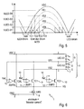
- FIG. 5 shows the voltage waveforms during a half grid period on the example of an LED chain 4 consisting of four segments 6 with the same number of LEDs 5. It is shown that in the area around the zero crossing of the line-side AC voltage 2 no LED 5 is operated and no LED current flows . In the further course of time of a positive half cycle, the voltage VDC 2 increases until the forward voltages of the LEDs 5 in the segment VLED-S1 6 is reached, current flows through the segment VLED-S1 6 and this segment 6 thus lights up. In the further course of the positive half cycle, the voltage VDC 2 continues to increase until the forward voltages of the LEDs 5 in the segments VLED-S1 6 and VLED-S2 6 are reached. From this point on, current also flows through the segment VLED-S2 6, which now also lights up.
- the embodiment with similar segments 6 may be advantageous for the assembly of an application, but is not a prerequisite for the functionality of the method.
- the voltage drop VQ across the current source 8 has been neglected in the illustration for better understanding.
- the constant current source 8 is shown with a control input, via which the constant current is controllable.
- the current profile of the constant current source can be adapted to the, for example, sinusoidal current characteristic of the rectified pulsating input voltage VDC. This adaptation leads to an improvement of the so-called power factor due to the reduction of interfering harmonics.
- a current path For the operation of an LED lamp on a dimmer which operates by means of a phase-gated (triac) or phase-section method (MOSFET or IGBT), a current path must be provided for charging a capacitor which determines the current flow angle within a half-wave of the mains voltage.
- triac phase-gated
- MOSFET phase-section method
- the previously described circuit 1 will only conduct current when the forward voltage of the first LED segment 6 has been reached and only then can the time-determining capacitor be charged. Without further measures, therefore, the maximum achievable with a dimmer current flow angle is reduced. To avoid this shortening, it is advantageous to have a to set up additional current path, which is already active when the mains voltage VDC is still less than the forward voltage of the first segment 6, for example, LED-S1.
- This current is called “Bleeder Current”, since it is not used to drive the LEDs 5 itself.
- the circuit is off FIG. 4 by a cascode or switching element TCBL 16 and a comparator or amplifier 15 AMPBL have been extended according to the same principle.
- the "bleeder current” continues to flow until VDC has exceeded the forward voltage of segment LED-S1 6. In this case, the voltage VS1 rises and the comparator 15 AMPBL deactivates the "bleeder path". While TCBL 16 is active, the ILED 8 power source provides the bleeder current.
- a "high side” current source can be controlled by a ground-side or a potential-separated current sensor.
- a cascode element 9 carries the current of the current source ILED 8, its voltage drop increases in accordance with the difference between the voltage VDC and the sum voltage of the active segment or segments 6 (LED-S1,. ..) until the next cascode element 10 takes over the current.
- This current flow in the linear region of the element 9 can be used to charge a capacitor 17.
- the charging voltage can be up to the forward voltage of the "next" segment 6 (eg LED-S2), without the Total current and the current flow in the LED segments 6 are affected.
- This charging process may be for a single or for a plurality of cascode elements 9, 10 with a corresponding plurality of capacitors 17, which in the FIG. 7 not shown, are performed.
- the capacitor 17 has not been charged up to the forward voltage of the next segment 6 (eg LED-S2) during the rising edge of the voltage VDC, it can continue to be charged during the falling edge of the voltage VDC, as long as the voltage difference between the instantaneous voltage VDC and the voltage across the capacitor 17 is even greater than the voltage across the capacitor 17 itself.
- the next segment 6 eg LED-S2
- the capacitor 17 behaves like a variable voltage segment.
- the FIG. 7 shows a corresponding circuit detail for an "energy reserve" capacitor CER and two LED segments LED-S1 and LED-S2.
- VDC voltage
- the voltage VS1 rises and the capacitor CER 17 is charged via the cascode element TCC 20.
- the potential in node VCER 19 is also raised and first controller AMP1 11 turns off first switch TC1 9 and the entire current of current source ILED 8 is charged to charge capacitor CER 17 used.
- a linear control of the switches 9, 10 and 20 designed as cascode elements is particularly advantageous here compared to switching with comparators in order to avoid a switching back and forth of the current, for example between the electronic switches TCC 20 and TC1 9.
- the voltage VS2 rises and the charging of the capacitor CER 17 is stopped.
- the switch TC1 9 was either already switched off or is switched off by the rise of the voltage in the node VCER 19. If necessary, the voltage VS2 can also be used additionally to deactivate the switch TC1 9.
- a capacitor 17 it is not absolutely necessary to stop the charging of a capacitor (eg 17) when the next LED segment 6 (eg LED-S2) becomes active, rather a capacitor 17 can also be parallel to two or more segments 6 are loaded. This simplifies the circuitry, but also increases the "Flicker Index", d. H. the relative ripple of the luminous flux, based on the waveform of the total current ILED.
- a second capacitor 18 is additionally arranged in the circuit and charged in the manner described above.
- a portion of the energy stored in the capacitor 17 or in the capacitors 17 and 18 can be used to reduce the ripple of the luminous flux occurring at twice the mains frequency, especially to close the Bestromungslücke, which arises when the voltage VDC below the forward voltage of a single segment 6 (LED-S1) decreases.
- the capacitor voltage is higher than the forward voltage of at least one LED segment 6.
- FIG. 8 A possible arrangement with four segments (LED-S1 to LED-S4) and two capacitors 17 and 18, which are sequentially charged and discharged in series to fill the current gap, shows the FIG. 8 .
- the "Bleeder Current" in the FIG. 8 not considered.
- this can from the FIG. 6 known circuit part in the arrangement of FIG. 8 be used.
- the cascode elements TC1 9, TC2 10 and TC3 21 are first turned on in succession, and the current of the constant current source ILED 8 flows through the segments 6 LED-S1, LED-S1 + LED-S2 and LED-S1 in the same order + LED-S2 + LED-S3. If the voltage VS3 reaches the remaining voltage on the capacitor CER1 17 plus the diode forward voltage of the diode D1 22, a charging current is fed to the capacitor CER1 17 and with a further increase in the voltage VDC, the voltage V CER1 also increases over the capacitor CER1.
- the control unit AMP3 23 controls the switch TC3 21, and the entire current of the current source ILED 8 is for charging the capacitor CER1 17 to disposal.
- the voltage change dVDC / dt is greater than the change dV CER1 / dt in the case of the current ILED 8.
- the capacitor CER1 17 must therefore be chosen to be sufficiently large. If this condition is not fulfilled, the current of the current source ILED 8 is divided between the cascode elements TC3 21 and TCC1 20 and only enough current is used to charge the capacitor CER1 17 that dV CER1 / dt and dVDC / dt are the same. The energization of the LEDs 5 of the segments 6 is not affected thereby.
- the switch TC4 26 takes over again the current of the source ILED 8.
- the cascode element TCC2 27 does not have to be controlled, but can be continuously active. This can be achieved, for example, by connecting the gate of this MOSFET switch 27 to the voltage VGC.
- the diodes D1 22 and D2 25 prevent the discharge of the capacitors CER1 17 and CER2 18 at a falling edge of voltage VDC.
- the charges accumulated in the capacitances CER1 17 and CER2 18 are used by way of example to energize the segment 6 LED-S4 as soon as the voltage VDC enters the range or drops below the forward voltage of segment 6 LED-S1.
- the required control signal is obtained in the same way as described in the control of the "Bleeder Current" already described above and in the associated FIG. 6 was presented.
- the AMPER 28 for power management and AMPBL 15 units may be combined into one unit if desired.
- a level adjusting stage LS 29 controls, with a control signal CRLER, a switching element TER 30 which connects the capacitors CER1 17 and CER2 18 in series. From the sum voltage of the two capacitors 17 and 18, the segment 6 LED-S4 is now fed.
- the current is defined by a current source IER 31.
- the current source IER 31 can be arranged anywhere in the discharge path.
- the discharge of the capacitors 17 and 18 connected in series by means of the switch TER 30 takes place starting from the first terminal of the capacitor 17 via the LEDs 5 of the segment LED-S4 6 and the fifth switch TC4 26, the sixth switch TCC2 27 to the second terminal of the second Capacitor CER2 18 and from the first terminal of this capacitor 18 further via the current source IER 31, the switching element TER 30 to the second terminal of the first capacitor 17th
- a circuit summary of the current source IER 31 with the switching element TER 30 may be advantageous in particular for an integrated solution.
- the dimensioning of the constant current source for the discharge current IER 31 should be such that at minimum supply voltage VDC, the sum voltage at the end of the discharge process is just higher than the forward voltage of the segment 6 LED-S4. This ensures that the current remains constant at the maximum level throughout the entire gap and that the efficiency of the circuit is maximized in relation to the selected topology of the LEDs 5.
- the discharging process ends when the voltage VDC is again high enough for the segment 6 LED-S1 to be energized.
- An extended discharge on both sides may be useful if the current of the source ILED 8 to improve the "Power Factor", ie to reduce the harmonic content in the mains current in response to the instantaneous voltage VDC is controlled and the current in segment 6 LED-S1 first smaller than the current of the source IER 31. Since the available charge in the capacitances CER1 17 and CER2 18 is limited, the current of the source IER 31 must be reduced when the discharge time is prolonged.
Landscapes
- Circuit Arrangement For Electric Light Sources In General (AREA)
- Led Devices (AREA)
Abstract
Description
Die Erfindung betrifft eine Anordnung zur Ansteuerung von Leuchtdioden, mit einem Eingang, an welchen eine Eingangswechselspannung anlegbar ist und einer mit den Ausgängen der Anordnung zur Ansteuerung von Leuchtdioden verbundenen Kette von in einer Reihe geschalteten LEDs, welche in mindestens zwei Segmente unterteilt ist und wobei jedes Segment der Kette mit einem Ende zumindest mittelbar mit einer Konstantstromquelle verbunden ist.The invention relates to an arrangement for driving light-emitting diodes, having an input to which an input AC voltage can be applied and connected to the outputs of the arrangement for driving LEDs connected chain of series-connected LEDs, which is divided into at least two segments and each Segment of the chain is connected at one end at least indirectly connected to a constant current source.
Die Erfindung betrifft auch ein Verfahren zur Ansteuerung von Leuchtdioden, bei welchem eine Kette von in Reihe geschalteten Leuchtdioden bereitgestellt wird, welche in Segmente unterteilt ist, wobei jedes Segment mehrere Leuchtdioden beinhalten kann und einen ersten Anschluss sowie einen zweiten Anschluss aufweist und wobei die Kette mit einer gleichgerichteten Eingangswechselspannung (VDC) derart betrieben wird, dass die Segmente (in Abhängigkeit der Amplitude der Eingangswechselspannung (VDC) nacheinander zu- und abgeschaltet werden.The invention also relates to a method for driving light-emitting diodes, in which a chain of series-connected light-emitting diodes is divided into segments, each segment may include a plurality of light-emitting diodes and having a first terminal and a second terminal and wherein the chain a rectified input AC voltage (VDC) is operated such that the segments (in dependence on the amplitude of the input AC voltage (VDC) and sequentially switched on and off.
LEDs (LED = Light Emitting Diode, Leuchtdiode) werden zunehmend für Beleuchtungszwecke eingesetzt, da sie gegenüber herkömmlichen Leuchtmitteln wie Glühlampen oder Fluoreszenzlampen eine Reihe von Vorteilen, insbesondere einen geringeren Energiebedarf und eine längere Lebensdauer, aufweisen. Aufgrund ihrer halbleitertypischen Strom-Spannungscharakteristik ist es sinnvoll, LEDs mit einem Konstantstrom zu betreiben.LEDs (LED = Light Emitting Diode, LED) are increasingly used for lighting purposes, as they compared to conventional bulbs such as incandescent or fluorescent lamps a number of advantages, in particular a lower energy consumption and a longer life, exhibit. Due to their semiconductor-typical current-voltage characteristics, it makes sense to operate LEDs with a constant current.
Beim Betrieb von Leuchtmitteln mit LEDs aus einem Lichtnetz sind daher schaltungstechnische Maßnahmen zu treffen, um aus einer versorgenden hohen Wechselspannung, welche beispielsweise 230 VAC betragen kann, den erforderlichen konstanten Gleichstrom mit der geringen Spannung von typischerweise 3 ... 4 V je LED zu erzeugen. Wobei diese Werte typischerweise für sogenannte weiße LEDs gelten und für andere LEDs abweichen können.When operating light sources with LEDs from a light network, therefore, circuit measures must be taken in order to produce the required constant direct current with the low voltage of typically 3... 4 V per LED from a supplying high alternating voltage, which may be for example 230 VAC , These values are typically valid for so-called white LEDs and may differ for other LEDs.
Neben dem verbreiteten Einsatz von sogenannten AC-DC-Konvertern, welche meist aus einem Gleichrichter und einem Schaltnetzteil bestehen, ist ein Verfahren bekannt, bei dem eine Kette von in Reihe geschalteten LEDs über eine oder mehrere lineare Stromquellen direkt aus der gleichgerichteten Wechselspannung angesteuert wird.In addition to the widespread use of so-called AC-DC converters, which usually consist of a rectifier and a switching power supply, a method is known in which a chain of LEDs connected in series is controlled via one or more linear current sources directly from the rectified AC voltage.
Diese Anordnung wird auch als "Direct AC LED" bezeichnet. Dazu kann vorteilhafterweise die LED-Kette in Segmente aufgeteilt werden, die entsprechend der momentanen Wechselspannung einzeln oder hintereinander geschaltet bestromt werden. Die Anzahl der in Reihe geschalteten LEDs und damit die Flussspannung der gesamten LED-Kette wird so ausgelegt, dass sie einem nennenswerten Anteil der Amplitude der Netzspannung entspricht, welcher beispielsweise im Bereich von 80 bis 90% der Amplitude der Netzspannung liegen kann.This arrangement is also referred to as "Direct AC LED". For this purpose, advantageously, the LED chain can be divided into segments, which are energized individually or in series according to the instantaneous AC voltage. The number of series-connected LEDs and thus the forward voltage of the entire LED chain is designed so that it corresponds to a significant proportion of the amplitude of the mains voltage, which may for example be in the range of 80 to 90% of the amplitude of the mains voltage.
Der Spannungsabfall über der linearen Stromquelle wird somit gering gehalten, was zu einem verhältnismäßig hohen Wirkungsgrad führt. Bei geringerer Momentanspannung wird nur ein Teil der LED-Kette, entsprechend der anordnungsseitigen Segmentierung der LEDs, ebenfalls mit relativ geringem Spannungsabfall über der zugehörigen Stromquelle angesteuert. Dadurch wird der Stromflusswinkel innerhalb einer halben Netzperiode vergrößert, was zu einer gleichmäßigeren Lichtabgabe führt. Optional kann der Strom der linearen Stromquelle oder Stromquellen entsprechend der momentanen Netzspannung moduliert werden, um den "Power Factor" zu erhöhen, d. h. den Oberwellengehalt des Versorgungsstroms gering zu halten.The voltage drop across the linear current source is thus kept low, resulting in a relatively high efficiency. At a lower instantaneous voltage, only a part of the LED chain, corresponding to the array-side segmentation of the LEDs, also with relatively low voltage drop across the associated power source driven. As a result, the flow angle is increased within half a mesh period, resulting in a more uniform light output. Optionally, the current of the linear current source or current sources may be modulated according to the instantaneous mains voltage to increase the "power factor", ie, to minimize the harmonic content of the supply current.
Vorteile dieses bekannten Verfahrens gegenüber der Verwendung von AC-DC Konvertern sind kleinere Bauform und geringere Kosten der Ansteuerelektronik sowie ein besseres EMV-Verhalten (EMV = elektro-magnetische Verträglichkeit) der Anordnung, da keine schnellen Schaltflanken auftreten.Advantages of this known method compared to the use of AC-DC converters are smaller design and lower costs of the control electronics and a better EMC behavior (EMC = electromagnetic compatibility) of the arrangement, since no fast switching edges occur.
Ein grundsätzlicher Nachteil besteht in der hohen Welligkeit der Lichtabgabe mit der doppelten Netzfrequenz, die von empfindlichen Personen als störend empfunden wird. Selbst bei einer konstanten Bestromung der LEDs reduziert sich die Lichtabgabe, wenn weniger Segmente, als in der LED-Kette angeordnet, aktiv sind.A fundamental disadvantage is the high waviness of the light output with twice the mains frequency, which is perceived by sensitive persons as disturbing. Even with a constant current supply to the LEDs, the light output is reduced if fewer segments than in the LED chain arranged, are active.
Wenn die Momentanspannung, mit welcher die LED-Ketten angesteuert werden, unter die Flussspannung des ersten Segments der Ketten absinkt, wird der Strom zu Null, d. h. in jeder Netzperiode gibt es zwei Lücken, in denen die LEDs nicht bestromt werden. Im Gegensatz zum Glühfaden einer Glühlampe, der eine erhebliche thermische Trägheit aufweist und damit die Welligkeit der zugeführten Leistung bedämpft, folgt die Lichtabgabe einer LED dem Strom praktisch verzögerungsfrei. Insbesondere diese Bestromungslücken können zu einem als unangenehm empfundenen Eindruck des "Flimmern" oder "Flackern" der Beleuchtung führen, welcher im englischen als "Flicker" bezeichnet wird.When the instantaneous voltage at which the LED strings are driven falls below the forward voltage of the first segment of the strings, the current becomes zero, i. H. There are two gaps in each grid period in which the LEDs are not energized. In contrast to the filament of an incandescent lamp, which has a considerable thermal inertia and thus attenuates the ripple of the supplied power, the light output of an LED follows the current virtually instantaneously. In particular, these energization gaps can lead to a perceived as unpleasant impression of "flicker" or "flicker" of the lighting, which is referred to in English as "flicker".
Ein weiterer schaltungstechnischer Nachteil der Ansteuerung besteht darin, dass die Umschaltschwellen der einzelnen Segmente an die Anzahl der LEDs je Segment und die tatsächliche Flussspannung angepasst werden müssen.Another circuit disadvantage of the control is that the switching thresholds of the individual segments to the number of LEDs per segment and the actual forward voltage must be adjusted.
Somit besteht die Aufgabe der Erfindung darin, eine Anordnung und ein Verfahren zur Ansteuerung von Leuchtdioden anzugeben, womit eine verbesserte Ansteuerung der LEDs ohne eine Verschlechterung des Wirkungsgrades und/oder des Oberwellengehalts erreicht wird.Thus, the object of the invention is to provide an arrangement and a method for driving light-emitting diodes, whereby an improved control of the LEDs without deterioration of the efficiency and / or the harmonic content is achieved.
Bei einer Anordnung zur Ansteuerung von Leuchtdioden wird daher vorgeschlagen, dass eine Kapazität in einer Reihenschaltung mit einem elektronischen Schalter zwischen einem Ende eines ersten Segments (z. B. LED-S3) und der Konstantstromquelle angeordnet ist, wobei ein erster Anschluss der Kapazität mit dem Ende und ein zweiter Anschluss der Kapazität mit dem Schalter verbunden sind, dass der Schalter zur Ansteuerung mit einer Steuereinheit verbunden ist, dass der zweite Anschluss der Kapazität über einen weiteren Schalter mit der Konstantstromquelle und mit einem Ende eines dem ersten Segment nachfolgenden Segments (z. B. LED-S4) verbunden ist und dass der weitere Schalter zur Ansteuerung mit einer weiteren Steuereinheit verbunden ist.In an arrangement for driving light-emitting diodes, it is therefore proposed that a capacitance is arranged in a series connection with an electronic switch between one end of a first segment (eg LED-S3) and the constant current source, wherein a first terminal of the capacitor with the End and a second terminal of the capacitance are connected to the switch, that the switch for driving is connected to a control unit, that the second terminal of the capacitance via another switch with the constant current source and with one end of the segment following the first segment (z. B. LED-S4) is connected and that the further switch for driving is connected to a further control unit.
Bezug nehmend auf ein in der
Die Ladung des Kondensators CER wird solange fortgesetzt, bis die Flussspannung der Segmente LED-S1 und LED-S2 überschritten wird. Für diesen Fall wird der Schalter TCC geöffnet und die Ladung verbleibt auf der Kapazität CER.The charge of the capacitor CER is continued until the forward voltage of the segments LED-S1 and LED-S2 is exceeded. In this case, the switch TCC is opened and the charge remains on the capacitor CER.
Zur Verbesserung des "Flicker Index" ist das Öffnen des Schalters TCC vorteilhaft, für die Realisierung der Erfindung an sich, aber nicht zwingend notwendig.To improve the "Flicker Index" the opening of the switch TCC is advantageous for the realization of the invention per se, but not absolutely necessary.
Die auf der Kapazität CER aufgesammelte Ladung wird zum Schließen der mit der doppelten Netzfrequenz auftretenden Stromlücken genutzt. Diese entstehen dann, wenn die Eingangswechselspannung VDC unter die Flussspannung eines einzigen Segments absinkt. Die Anordnung wird so dimensioniert, dass die Spannung VCER auf dem Kondensator CER größer ist als die Flussspannung eines LED-Segments. In den Stromlücken wird nun der Kondensator mittels geeigneter Schalter (TER) mit einem LED-Segment (LED-S4) oder aber nur mit einer oder mehreren LEDs innerhalb des LED-Segments verbunden, wobei sich der Kondensator CER über das LED-Segment oder die LEDs entlädt und diese leuchten. Durch diese Lichtabgabe der LEDs in der Zeit einer Stromlücke, in welcher nach dem Stand der Technik kein Licht abgegeben wird, wird die Welligkeit der Lichtabgabe verbessert.The charge accumulated on the CER capacitance is used to close the power gaps that occur at twice the mains frequency. These occur when the input AC voltage VDC drops below the forward voltage of a single segment. The arrangement is dimensioned so that the voltage V CER on the capacitor CER is greater than the forward voltage of an LED segment. In the current gaps, the capacitor is then connected by means of suitable switches (TER) with an LED segment (LED-S4) or only with one or more LEDs within the LED segment, wherein the capacitor CER via the LED segment or the LEDs discharges and these light up. By this light emission of the LEDs in the time of a current gap in which no light is emitted in the prior art, the ripple of the light output is improved.
Weitere Ausgestaltungen sehen vor, mehrere Kondensatoren aufzuladen und somit mehrere LED-Segmente oder LEDs in den Stromlücken mit einer Spannung zu versorgen. Alternativ können die Kondensatoren zur Erhöhung der resultierenden Spannung in den Stromlücken hintereinander geschaltet werden und somit beispielsweise ein LED-Segment oder Einzel-LEDs mit höherer Flussspannung zum Leuchten gebracht werden.Further embodiments provide for charging a plurality of capacitors and thus supplying a plurality of LED segments or LEDs in the current gaps with a voltage. Alternatively, the capacitors can be connected in series to increase the resulting voltage in the current gaps and thus, for example, an LED segment or single LEDs with higher forward voltage can be lit.
Eine weitere Möglichkeit besteht in der Nutzung einer Strombegrenzungs- oder Stromregelungsanordnung im Entladestromkreis. Derart wird durch angepasste Dimensionierung der Stromregelung die im Kondensator bzw. den Kondensatoren gespeicherte Energie gleichmäßig und soweit die Flussspannung der LEDs es zulässt vollständig während der Stromlücke abgegeben. Außerdem ist derart eine Regelung der Helligkeit und der Leuchtdauer der LEDs möglich.Another option is to use one Current limiting or current control arrangement in the discharge circuit. In this way, by adapted dimensioning of the current regulation, the energy stored in the capacitor or the capacitors is emitted evenly and as far as the forward voltage of the LEDs permits it completely during the current gap. In addition, such a regulation of the brightness and the duration of the LEDs is possible.
In einer Ausgestaltung der Erfindung ist vorgesehen, eine zweite Kapazität in einer zweiten Reihenschaltung mit einem elektronischen Schalter zwischen einem Ende eines nachfolgenden Segments und der Konstantstromquelle angeordnet ist.In one embodiment of the invention, a second capacitor is arranged in a second series circuit with an electronic switch between one end of a subsequent segment and the constant current source.
Neben einer ersten Kapazität wird eine zweite Kapazität in die Anordnung eingebracht, welche ebenfalls aufgeladen wird, für den Fall, dass die Amplitude der Eingangswechselspannung VDC groß genug ist. Diese zweite Kapazität wird in den Stromlücken mittels einer geeigneten Anordnung von Schaltelementen mit der ersten Kapazität in Reihe geschaltet, wobei sich die Spannungen über den Kapazitäten summieren VCER1 + VCER2 = VGES. Durch diese Maßnahme kann ein LED-Segment auch für den Fall in einer Stromlücke betrieben werden, dass eine Spannung VCER1 oder VCER2 auf einer einzelnen Kapazität nicht die Größe der Flussspannung des LED-Segments erreicht.In addition to a first capacitance, a second capacitance is introduced into the arrangement, which is also charged in the event that the amplitude of the input AC voltage VDC is large enough. This second capacitance is serially connected in the current gaps by means of a suitable arrangement of switching elements having the first capacitance, the voltages summing over the capacitances V CER1 + V CER2 = V GES . By virtue of this measure, an LED segment can also be operated in the event of a current gap so that a voltage V CER1 or V CER2 on a single capacitance does not reach the magnitude of the forward voltage of the LED segment.
Alternativ kann auch in dieser Ausführung nur eine LED oder mehrere LEDs innerhalb eines LED-Segments betrieben werden.Alternatively, only one LED or several LEDs within an LED segment can also be operated in this embodiment.
Bei einem Verfahren zur Ansteuerung von Leuchtdioden wird vorgeschlagen, dass bei einem Überschreiten einer vorgegebenen Einschaltschwelle der Eingangswechselspannung (VDC) ein Ladevorgang mindestens einer Kapazität, gespeist durch die Eingangswechselspannung (VDC), gestartet wird und dass bei einem Unterschreiten einer zweiten Schaltschwelle der Eingangswechselspannung (VDC) eine Entladung der Kapazität über ein Segment erfolgt.In a method for driving light-emitting diodes, it is proposed that when a predetermined switch-on threshold of the input AC voltage (VDC) is exceeded, charging of at least one capacitor, fed by the input AC voltage (VDC), is started and if the threshold drops below a second switching threshold the input AC voltage (VDC) is a discharge of capacity over a segment.
Das Verfahren sieht eine Aufladung eines Ladekondensators oberhalb eines Schwellwertes vor. Hierzu kann ein Vergleich zwischen der Eingangswechselspannung und der Einschaltschwelle, welcher vorher ein Spannungswert zugewiesen wurde, erfolgen. Das Verfahren benötigt diesen Vergleich aber nicht zwingend. Alternativ wird durch einen Anschluss eines Ladekondensators an einem Ende eines LED-Segmentes erreicht, dass nach einem Erreichen der Flussspannung für das betreffende Element nicht nur ein Stromfluss durch das Segment (LED-S1) selbst und dessen weitere Schaltungselemente, sondern auch ein Ladestrom für die Kapazität CER erzeugt wird. Hierfür ist das Ende des Segments LED-S1 über einen geschlossenen Schalter TC1 mit einer Konstantstromquelle ILED verbunden. Parallel hierzu ist auch die Kapazität CER über einen geschlossenen Schalter TCC mit dieser Konstantstromquelle ILED verbunden. Mittels einer geeigneten Ansteuerung der Schalter TC1 und TCC wird sichergestellt, dass auch nachfolgende LED-Segmente (LED-S2, LED-S3, ...) bei steigender Eingangswechselspannung VDC betrieben werden können und dass die Ladung auf dem Kondensator CER gehalten werden kann.The method provides for a charging of a charging capacitor above a threshold value. For this purpose, a comparison between the input AC voltage and the switch-on threshold, which was previously assigned a voltage value, take place. However, the method does not necessarily require this comparison. Alternatively, it is achieved by connecting a charging capacitor at one end of an LED segment, that after reaching the forward voltage for the element concerned not only a current flow through the segment (LED-S1) itself and its other circuit elements, but also a charging current for the Capacity CE is generated. For this purpose, the end of the segment LED-S1 is connected via a closed switch TC1 to a constant current source ILED. Parallel to this, the capacitance CER is also connected to this constant current source ILED via a closed switch TCC. By means of a suitable control of the switches TC1 and TCC it is ensured that also subsequent LED segments (LED-S2, LED-S3,...) Can be operated with increasing input AC voltage VDC and that the charge can be held on the capacitor CER.
Für den Fall, dass die Eingangswechselspannung VDC unter eine zweite Schaltschwelle fällt, welche vor dem Verfahrensablauf vorgegeben wird, wird der geladene Kondensator CER mit einem LED-Segment derart verbunden, dass sich die Ladung des Kondensators CER über die LEDs des Segments entlädt und durch diesen Entladestrom eine Lichtabgabe der LEDs erfolgt.In the event that the input AC voltage VDC falls below a second switching threshold, which is predetermined before the procedure, the charged capacitor CER is connected to an LED segment such that the charge of the capacitor CER discharges through the LEDs of the segment and through this Discharge current, a light emission of the LEDs takes place.
In einer Ausführungsform der Erfindung ist vorgesehen, dass die Einschaltschwelle bei einem höheren Spannungswert der Eingangswechselspannung (VDC) liegt als die zweite Schaltschwelle.In one embodiment of the invention, it is provided that the switch-on threshold is at a higher voltage value of the input AC voltage (VDC) than the second switching threshold.
Das Verfahren kann das Unterschreiten der Flussspannung des ersten Segments LED-S1 detektieren und somit die Kondensatorentladung über dieses oder ein anderes Segment starten. Zur Ladung des Kondensators CER ist es notwendig, dass die Eingangswechselspannung (VDC) mindestens den Wert der Flussspannung des ersten Segments LED-S1 überschritten hat.The method can detect the drop below the forward voltage of the first segment LED-S1 and thus start the capacitor discharge via this or another segment. To charge the capacitor CER, it is necessary that the input AC voltage (VDC) has exceeded at least the value of the forward voltage of the first segment LED-S1.
In einer anderen Ausführung der Erfindung ist vorgesehen, dass die Entladung der Kapazität nur über einen Teil der im Segment angeordneten LEDs erfolgt.In another embodiment of the invention, it is provided that the discharge of the capacitance takes place only over part of the LEDs arranged in the segment.
Neben der Möglichkeit alle LEDs eines Segments in den Entladestromkreis der Kapazität einzuschalten kann gemäß des Verfahrens auch nur ein Teil der LEDs des Segments einbezogen werden. Dies kann beispielsweise für den Fall vorteilhaft sein, dass die Spannung VCER auf der Kapazität CER nicht die Größe der Flussspannung des mehrere LEDs beinhaltenden Segments erreicht.In addition to the possibility to switch all the LEDs of a segment into the discharge circuit of the capacitance, according to the method only a part of the LEDs of the segment can be included. This may be advantageous, for example, in the event that the voltage V CER on the capacitor CER does not reach the magnitude of the forward voltage of the segment comprising several LEDs.
Die Erfindung soll nachfolgend anhand eines Ausführungsbeispiels näher erläutert werden. In den zugehörigen Zeichnungen zeigt
- Fig. 1
- eine mögliche Ausführung einer Anordnung zur Ansteuerung von Leuchtdioden nach dem Stand der Technik in einer Variante als "Direct AC LED Drivers",
- Fig. 2
- eine andere mögliche Ausführung einer Anordnung zur Ansteuerung von Leuchtdioden nach dem Stand der Technik in einer Variante als "Direct AC LED Drivers",
- Fig. 3
- eine erfindungsgemäße Schaltungsanordnung zur Ansteuerung von Leuchtdioden mit einer automatischen Anpassung der Strompfade an die Flussspannung der LED Segmente,
- Fig. 4
- eine weitere erfindungsgemäße Schaltungsanordnung zur Ansteuerung von Leuchtdioden mit einer alternativen automatischen Anpassung mit gestuften Gate-Spannungen,
- Fig. 5
- eine Darstellung der Spannungsverläufe der gleichgerichteten Netzspannung und der Segmentspannungen über eine halbe Netzperiode,
- Fig. 6
- eine Schaltungsanordnung zur automatischen Steuerung eines "Bleeder Current",
- Fig. 7
- eine Schaltungsanordnung zur automatischen Steuerung der Aufladung eines "Energiereserve Kondensators" CER
- Fig. 8
- eine Schaltungsanordnung zur automatischen Steuerung des Lade- und Entladevorgangs von beispielhaft zwei Kondensatoren CER1 und CER2,
- Fig. 9
- eine Darstellung der Spannungsverläufe an den Kondensatoren CER1 und CER2 über eine halbe Netzperiodendauer und
- Fig. 10
- eine Ausschnittsvergrößerung der Darstellung der Spannungsverläufe aus der
Figur 8
- Fig. 1
- a possible embodiment of an arrangement for controlling light-emitting diodes according to the prior art in a variant as "Direct AC LED Drivers",
- Fig. 2
- another possible embodiment of an arrangement for controlling light-emitting diodes according to the prior art in a variant as "Direct AC LED Drivers",
- Fig. 3
- a circuit arrangement according to the invention for controlling light-emitting diodes with an automatic adaptation of the current paths to the forward voltage of the LED segments,
- Fig. 4
- a further circuit arrangement according to the invention for driving light-emitting diodes with an alternative automatic adaptation with stepped gate voltages,
- Fig. 5
- a representation of the voltage waveforms of the rectified mains voltage and the segment voltages over half a grid period,
- Fig. 6
- a circuit arrangement for the automatic control of a "bleeder current",
- Fig. 7
- a circuit for automatically controlling the charging of an "energy reserve capacitor" CER
- Fig. 8
- a circuit arrangement for automatically controlling the charging and discharging process of, for example, two capacitors CER1 and CER2,
- Fig. 9
- a representation of the voltage waveforms on the capacitors CER1 and CER2 over half a network period and
- Fig. 10
- an enlarged detail of the representation of the voltage waveforms from the
FIG. 8 ,
In der
In der Darstellung in
In der Ausgestaltung nach
Nachfolgend wird die erfindungsgemäße automatische Anpassung der Schaltschwellen an die Flussspannung der Segmente beschrieben.The automatic adaptation of the switching thresholds according to the invention to the forward voltage of the segments will be described below.
Die
Die Anode der "oberen" LED 5 des Segments LED-S1 6 ist mit der Versorgungsspannung VDC 2, d. h. der gleichgerichteten Netzspannung, verbunden. Jedes Segment 6 der Kette 4 weist einen ersten und einen zweiten Anschluss 7 auf. In der
Die gesamte LED-Kette 6 wird über diese zu- und abschaltbaren Schaltmittel 9, 10 von einer gemeinsamen masseseitigen Stromquelle 8 ILED gespeist. Oberhalb der Stromquelle 8 befinden sich für jeden Strompfad n als Schaltmittel sogenannte Kaskoden-Elemente TC1 und TC2 9, 10, gebildet beispielsweise durch MOSFETs, Bipolar-Transistoren oder IGBTs. Als Kaskode bezeichnet man die Hintereinanderschaltung zweier Transistoren, wobei der "untere" Transistor (bei n-Kanal oder NPN) die Steuerung übernimmt, während der "obere" Transistor zur Erhöhung der Spannungsfestigkeit und/oder der Ausgangsimpedanz dient.The
Derart werden n Stufen innerhalb der Anordnung ausgebildet, welche jeweils ein n-tes LED-Segment 6 und mindestens ein n-tes Schaltmittel 9 oder 10 umfassen. Die erste Stufe umfasst das erste Segment 6 der Kette 4 sowie das erste Schaltmittel 9. Zusätzlich kann auch noch ein das erste Schaltmittel 9 ansteuerndes Element beinhaltet sein. Im Beispiel der
Die Kaskoden-Elemente 9, 10 begrenzen die Spannung VQ über der Stromquelle 8 und nehmen einen Teil der Differenz zwischen momentaner VDC und der Flussspannung der aktiven Segmente 6 der LED-Kette 4 auf. Die an die Kaskoden-Elemente 9, 10 angelegte Gate- bzw. Basisspannung VGC bestimmt die maximale Spannung VQ. Für die automatische Schwellen-Adaption ist es vorteilhaft, diese Spannung niedrig zu halten.The
Steigt die Spannung VDC 2 von einem Wert kleiner als die Flussspannung des Segments LED-S1 6 beginnend an, so wird zunächst beim Erreichen der Flussspannung das Segment LED-S1 6 beginnen, Strom zu führen. Ist der durch die Stromquelle 8 begrenzte Strom erreicht und hat VQ den vom Kaskoden-Element 9, 10 begrenzten Wert erreicht, so steigt bei weiterer Erhöhung von VDC 2 die Segmentspannung VS1 an, während VQ annähernd konstant bleibt.If the
Zunächst fließt kein Strom durch das Segment LED-S2 6 und die Segmentspannung VS2 entspricht etwa der Spannung VQ. Erreicht VDC die Summe der Flussspannungen von LED-S1 6 und LED-S2 6, so beginnt auch LED-S2 6 zu leiten, und der Strom teilt sich zwischen TC1 9 und TC2 10 auf. Der Summenstrom wird weiterhin durch die gemeinsame Stromquelle 8 ILED bestimmt. Bei weiterer Erhöhung von VDC 2 steigt nun die Spannung VS2 gegenüber VQ an. Dieser Anstieg signalisiert, dass LED-S2 6 leitend ist und der Strompfad über TC1 9 abgeschaltet werden kann. Die Abschaltung kann beispielsweise über einen Verstärker oder Komparator 11 AMP erfolgen, dessen Vergleichswert um einen festlegbaren Betrag über der Spannung VQ liegt. Zur Vermeidung von Oszillationen um den Schaltpunkt ist es vorteilhaft, einen Komparator 11 mit einer Hysterese zu versehen. Dies gilt insbesondere für den Fall, dass als Kaskoden-Elemente 9, 10 relativ hochohmige MOSFETs verwendet werden. Bei Einsatz von Bipolartransistoren muss deren Basisstrom begrenzt werden.First, no current flows through the segment LED-
Vorteilhaft zur Vermeidung eventueller Störabstrahlung durch die Umschaltvorgänge ist eine graduelle Abschaltung, etwa durch einen Verstärker oder einfachen Inverter beispielsweise mit mäßiger Verstärkung anstelle des Komparators.Advantageous for avoiding possible noise radiation by the switching operations is a gradual shutdown, such as an amplifier or simple inverter, for example, with moderate gain instead of the comparator.
Eine Übernahme des Stroms durch TC2 10 ohne Schalten von TC1 9 ist ebenfalls möglich, indem eine Steuerspannung VG2 > VG1 angelegt wird, wie in der
Bei größerer Anzahl "n" von LED Segmenten kann dies zu einer erheblichen "Spreizung" der steuernden Gate-Spannungen VG1 bis VGn führen. Vorteilhaft ist daher die Kombination der gestuften Ansteuerspannungen mit dem Abschalten vorhergehender Strompfade.With larger numbers "n" of LED segments, this can lead to a significant "spread" of the controlling gate voltages VG1 to VGn. Advantageously, therefore, the combination of the stepped Ansteuerspannungen with the shutdown previous rungs.
Besteht die LED-Kette 4 aus mehr als zwei Segmenten 6, so wiederholt sich der beschriebene Vorgang bei weiterem Anstieg von VDC 2 für die folgenden Stufen oder Strompfade n+1, n+2 ... usw. Für das "letzte" Segment 6 der Kette 4 ist nicht unbedingt ein Kaskoden-Element 9, 10 erforderlich, es ist jedoch schaltungstechnisch vorteilhaft zur Begrenzung der Spannung VQ. Dieses letzte Kaskoden-Element 9, 10 muss nicht geschaltet werden. In der
Nachdem VDC 2 seine Amplitude überschritten hat und die Spannung wieder abfällt, werden mit derselben Schaltung die Kaskoden-Elemente 9, 10 in umgekehrter Reihenfolge entsprechend der momentanen Spannung wieder aktiviert.After
Die
Dieser Vorgang ist weiter dargestellt, bis alle Segmente 6 VLED-S1 bis VLED-S4 stromdurchflossen sind und leuchten. Nach dem Erreichen des Maximums der Spannung VDC 2 nimmt diese sinusförmig ab, was dazu führt, dass die Flussspannung des Segments VLED-S4 6 nicht mehr erreicht wird. Dies führt zur Unterbrechung des Stromflusses im Segment VLED-S4 6 und somit zu dessen Abschaltung. Nachfolgend werden nacheinander die Segmente VLED-S3 6, VLED-S2 6 und VLED-S1 6 abgeschalten, wodurch kein Strom mehr durch die Kette 4 fließt.This process is further illustrated until all
Die Ausführung mit gleichartigen Segmenten 6 kann vorteilhaft für die Bestückung einer Applikation sein, ist aber keine Voraussetzung für die Funktionalität des Verfahrens. Der Spannungsabfall VQ über der Stromquelle 8 wurde in der Darstellung zum besseren Verständnis vernachlässigt.The embodiment with
In den
Für den Betrieb einer LED-Leuchte an einem Dimmer, welcher mittels eines Phasenanschnitts- (Triac) oder Phasenabschnittsverfahrens (MOSFET oder IGBT) arbeitet, muss ein Strompfad zum Aufladen eines Kondensators, der den Stromflusswinkel innerhalb einer Halbwelle der Netzspannung bestimmt, bereitgestellt werden.For the operation of an LED lamp on a dimmer which operates by means of a phase-gated (triac) or phase-section method (MOSFET or IGBT), a current path must be provided for charging a capacitor which determines the current flow angle within a half-wave of the mains voltage.
Die zuvor beschriebene Schaltung 1 führt erst dann Strom, wenn die Flussspannung des ersten LED-Segments 6 erreicht ist und erst dann kann der zeitbestimmende Kondensator geladen werden. Ohne weitere Maßnahmen verringert sich daher der maximale mit einem Dimmer erreichbare Stromflusswinkel. Um diese Verkürzung zu vermeiden, ist es vorteilhaft, einen zusätzlichen Strompfad einzurichten, der bereits aktiv ist, wenn die Netzspannung VDC noch kleiner als die Flussspannung des ersten Segments 6, beispielsweise LED-S1, ist.The previously described
Dieser Strom wird als "Bleeder Current" bezeichnet, da er nicht zur Ansteuerung der LEDs 5 selbst genutzt wird. In der
Die Polarität der beschriebenen Topologie kann umgedreht werden, d. h. die Stromquelle 8 liegt dann an der positiven Versorgungsspannung (VDC) 2 und die Katode der "untersten" LED 5 an der negativen Versorgung (GND). Ebenso gut kann eine "high side" Stromquelle durch einen masseseitigen oder auch durch einen potenzialgetrennten Stromfühler gesteuert werden.The polarity of the described topology can be reversed, i. H. the
Nachfolgend wird das erfindungsgemäße Auffüllen der sogenannten Stromlücken bei der Ansteuerung der LEDs mithilfe der Schaltungsanordnung der
Sobald bei einem Anstieg der Spannung VDC 2 wie zuvor beschrieben ein Kaskoden-Element 9 den Strom der Stromquelle ILED 8 führt, erhöht sich dessen Spannungsabfall entsprechend der Differenz aus der Spannung VDC und der Summenspannung des oder der aktiven Segmente 6 (LED-S1, ...), bis das nächste Kaskoden-Element 10 den Strom übernimmt. Dieser Stromfluss im Linearbereich des Elements 9 kann genutzt werden, um damit einen Kondensator 17 aufzuladen. Die Ladespannung kann bis zur Flussspannung des "nächsten" Segments 6 (z. B. LED-S2) betragen, ohne dass der Summenstrom und der Stromfluss in den LED-Segmenten 6 beeinträchtigt werden. Dieser Ladevorgang kann für ein einzelnes oder für mehrere Kaskoden-Elemente 9, 10 mit entsprechend mehreren Kondensatoren 17, welche in der
Wurde der Kondensator 17 während der steigenden Flanke der Spannung VDC nicht bis zur Flussspannung des nächsten Segments 6 (z. B. LED-S2) aufgeladen, so kann er während der fallenden Flanke der Spannung VDC weiter geladen werden, solange die Spannungsdifferenz, zwischen der momentanen Spannung VDC und der Spannung über dem Kondensator 17 noch größer ist, als die Spannung über dem Kondensator 17 selbst.If the
Die Verteilung des Stroms zwischen dem "regulären" Pfad zum Betreiben der LEDs 5 der Segmente 6 und dem Pfad zum Laden des Kondensators 17 oder eines weiteren, erfolgt vorteilhaft nach demselben Verfahren, wie es zuvor für die automatische Anpassung an die Flussspannungen der LED-Segmente 6 beschrieben wurde.The distribution of the current between the "regular" path for operating the
Der Kondensator 17 verhält sich dabei wie ein Segment mit veränderlicher Spannung. Die
Ist der Spannungsanstieg von VDC nicht ausreichend steil, damit der Kondensator CER 17 den gesamten Strom aufnehmen kann, so reduziert sich die Spannung im Knoten VCER 19, und der Schalter TC1 9 wird aktiv. Eine lineare Ansteuerung der als Kaskoden-Elemente ausgeführten Schalter 9, 10 und 20 ist hier besonders vorteilhaft gegenüber dem Schalten mit Komparatoren, um ein Hin- und Herschalten des Stroms beispielsweise zwischen den elektronischen Schaltern TCC 20 und TC1 9 zu vermeiden.If the voltage rise of VDC is not steep enough for the
Erreicht die Spannung VDC die Summe der Flussspannungen der Segmente LED-S1 6 und LED-S2 6, so steigt die Spannung VS2 an und der Ladevorgang des Kondensators CER 17 wird abgebrochen. Der Schalter TC1 9 war entweder bereits abgeschaltet oder wird durch das Ansteigen von der Spannung im Knoten VCER 19 abgeschaltet. Bedarfsweise kann die Spannung VS2 auch zusätzlich genutzt werden, um dem Schalter TC1 9 zu deaktivieren.When the voltage VDC reaches the sum of the forward voltages of the segments LED-
Sind alle LED-Segmente 6 aktiv, so kann ein Kondensator aus der Differenz der Wechseleingangsspannungen VDC und der Summe der Flussspannungen der Segmente VLED (VLED = VLED-S1 + VLED-S2 + VLED-S3 + ... + VLED-Sx) geladen werden. Da der Verlauf der Netzspannung im Bereich der Amplitude recht flach ist und damit die zur Verfügung stehende Zeit zum Laden eines Kondensators (z. B. CER 17) relativ lang ist, kann hier verhältnismäßig viel Ladung auf der Kapazität angesammelt werden.If all
Es ist nicht zwingend notwendig, den Ladevorgang eines Kondensators (z. B. 17) zu stoppen, wenn das nächste LED Segment 6 (z. B. LED-S2) aktiv wird, vielmehr kann ein Kondensator 17 auch parallel zu zwei oder mehreren Segmenten 6 geladen werden. Dies vereinfacht den Schaltungsaufwand, erhöht allerdings auch den "Flicker Index", d. h. die relative Welligkeit des Lichtstroms, bezogen auf die Kurvenform des Gesamtstroms ILED.It is not absolutely necessary to stop the charging of a capacitor (eg 17) when the next LED segment 6 (eg LED-S2) becomes active, rather a
In einer Ausführung, welche in der
Ein Teil der im Kondensator 17 bzw. in den Kondensatoren 17 und 18 gespeicherten Energien kann genutzt werden, um die mit der doppelten Netzfrequenz auftretende Welligkeit des Lichtstroms zu reduzieren, speziell um die Bestromungslücke zu schließen, die entsteht, wenn die Spannung VDC unter die Flussspannung eines einzelnen Segments 6 (LED-S1) absinkt. Dazu ist es notwendig, dass die Kondensatorspannung höher ist, als die Flussspannung mindestens eines LED-Segments 6. Abhängig von der Dimensionierung der Schaltung kann es erforderlich sein, die Kondensatoren 17, 18 während des Entladevorgangs hintereinander zu schalten.A portion of the energy stored in the
Eine mögliche Anordnung mit vier Segmenten (LED-S1 bis LED-S4) und zwei Kondensatoren 17 und 18, die sequenziell geladen und zum Auffüllen der Stromlücke in Reihe geschaltet entladen werden, zeigt die
Bei steigender Spannung VDC werden zunächst nacheinander die Kaskoden-Elemente TC1 9, TC2 10 und TC3 21 leitend und der Strom der Konstantstromquelle ILED 8 fließt in derselben Reihenfolge durch die Segmente 6 LED-S1, LED-S1 + LED-S2 und LED-S1 + LED-S2 + LED-S3. Erreicht die Spannung VS3 die noch verbliebene Spannung am Kondensator CER1 17 zuzüglich der Diodenflussspannung der Diode D1 22, so wird ein Ladestrom in den Kondensator CER1 17 eingespeist und bei einem weiteren Anstieg der Spannung VDC erhöht sich auch die Spannung VCER1 über der Kapazität CER1. Die Steuereinheit AMP3 23 steuert den Schalter TC3 21 zu, und der gesamte Strom der Stromquelle ILED 8 steht zum Laden des Kondensators CER1 17 zur Verfügung.As the voltage VDC rises, the
Voraussetzung hierfür ist, dass die Spannungsänderung dVDC/dt größer ist als die Änderung dVCER1/dt beim Strom ILED 8. Der Kondensator CER1 17 ist also hinreichend groß zu wählen. Ist diese Bedingung nicht erfüllt, so teilt sich der Strom der Stromquelle ILED 8 zwischen den Kaskoden-Elementen TC3 21 und TCC1 20 auf und es wird nur so viel Strom zum Laden von der Kapazität CER1 17 genutzt, dass dVCER1/dt und dVDC/dt gleich sind. Die Bestromung der LEDs 5 der Segmente 6 wird dadurch aber nicht beeinflusst.The prerequisite for this is that the voltage change dVDC / dt is greater than the change dV CER1 / dt in the case of the
Wird nach einem weiteren Anstieg der Spannung VDC auch die Flussspannung von des Segments 6 LED-S4 überschritten, so wird der Ladevorgang der Kapazität CER1 17 durch einen Schaltvorgang der Steuereinheit AMPC1 24 und Schalters TCC1 20 beendet. Bis zum Erreichen der auf Kapazität CER2 18 verbliebenen Spannung VCER2 zuzüglich der Diodenflussspannung der Diode D2 25 führt der Schalter TC4 26 den Strom der Stromquelle ILED 8. Danach wiederholt sich der oben für die Schalter TC3 21 und TCC1 20 beschriebene Vorgang in den Kaskoden-Elementen TC4 26 und TCC2 27 und die Kapazität CER2 18 wird aufgeladen. Dieser Ladevorgang wird beendet, wenn die Spannung VDC nach dem Überschreiten ihrer Amplitude wieder so weit abgefallen ist, dass die Diode D2 25 sperrt. Danach übernimmt der Schalter TC4 26 wieder den Strom der Quelle ILED 8. Das Kaskoden-Element TCC2 27 muss nicht angesteuert werden, sondern kann kontinuierlich aktiv sein. Dies kann beispielsweise dadurch erreicht werden, dass das Gate dieses MOSFET-Schalters 27 mit der Spannung VGC verbunden wird. Die Dioden D1 22 und D2 25 verhindern die Entladung der Kondensatoren CER1 17 und CER2 18 bei einer fallenden Flanke von Spannung VDC.If, after a further increase in the voltage VDC, the forward voltage of the
Die in den Kapazitäten CER1 17 und CER2 18 akkumulierten Ladungen werden beispielhaft genutzt, um das Segment 6 LED-S4 zu bestromen, sobald die Spannung VDC in den Bereich oder unter die Flussspannung des Segments 6 LED-S1 absinkt. Das hierfür erforderliche Steuersignal wird auf dieselbe Weise gewonnen, wie bei der Ansteuerung des "Bleeder Current" bereits oben beschrieben und in der zugehörigen
In einer Ausführung können gegebenenfalls die Einheiten AMPER 28 zur Steuerung der Energiereserve und AMPBL 15 zu einer Einheit zusammengefasst werden. Eine Stufe zur Pegelanpassung LS 29 steuert mit einem Steuersignal CRLER ein Schaltelement TER 30, das die Kondensatoren CER1 17 und CER2 18 in Reihe schaltet. Aus der Summenspannung der beiden Kondensatoren 17 und 18 wird nun das Segment 6 LED-S4 gespeist. Der Strom wird über eine Stromquelle IER 31 definiert. Die Stromquelle IER 31 kann an einer beliebigen Stelle im Entladepfad angeordnet werden. Die Entladung der mittels des Schalters TER 30 in Reihe geschalteten Kapazitäten 17 und 18 erfolgt beginnend vom ersten Anschluss der Kapazität 17 über die LEDs 5 des Segments LED-S4 6 und den fünften Schalter TC4 26, den sechsten Schalter TCC2 27 zum zweiten Anschluss des zweiten Kondensators CER2 18 und vom ersten Anschluss dieses Kondensators 18 weiter über die Stromquelle IER 31, das Schaltelement TER 30 zum zweiten Anschluss des ersten Kondensators 17.In one embodiment, the AMPER 28 for power management and AMPBL 15 units may be combined into one unit if desired. A level
Eine schaltungstechnische Zusammenfassung der Stromquelle IER 31 mit dem Schaltelement TER 30 kann insbesondere für eine integrierte Lösung vorteilhaft sein.A circuit summary of the
In der
In der
Für dieses Beispiel wurde angenommen, dass die Kapazität CER2 18 größer als die Kapazität CER1 17 ist. Diese Annahme ist für die Funktion der Schaltung aber nicht notwendig.For this example, it has been assumed that the
Die Dimensionierung der Konstantstromquelle für den Entladestrom IER 31 sollte so erfolgen, dass bei minimaler Versorgungsspannung VDC die Summenspannung am Ende des Entladevorgangs gerade noch höher ist, als die Flussspannung des Segments 6 LED-S4. Damit wird gewährleistet, dass der Strom während der gesamten Lücke auf maximalem Niveau konstant bleibt und der Wirkungsgrad der Schaltung bezogen auf die gewählte Topologie der LEDs 5 maximal wird.The dimensioning of the constant current source for the discharge
Da bei höherer Versorgungsspannung VDC mehr Ladung im Kondensator CER2 18 gespeichert werden kann, ist auch eine Steuerung des Stromes der Quelle IER 31 in Abhängigkeit von der Höhe der Versorgung VDC oder der Spannungsdifferenz zwischen VDC und der Flussspannung der LED-Kette 4 vorteilhaft.Since at higher supply voltage VDC more charge can be stored in the
Beispielhaft endet der Entladevorgang, wenn die Spannung VDC wieder hoch genug ist, damit das Segment 6 LED-S1 bestromt wird. Ein zu beiden Seiten verlängerter Entladevorgang kann sinnvoll sein, wenn der Strom der Quelle ILED 8 zur Verbesserung des "Power Factor", also zur Reduzierung des Oberwellengehalts im Netzstrom in Abhängigkeit von der Momentanspannung VDC gesteuert wird und der Strom im Segment 6 LED-S1 zunächst kleiner ist als der Strom der Quelle IER 31. Da die verfügbare Ladung in den Kapazitäten CER1 17 und CER2 18 begrenzt ist, muss der Strom der Quelle IER 31 reduziert werden, wenn die Entladezeit verlängert wird.By way of example, the discharging process ends when the voltage VDC is again high enough for the
Der beschriebene Vorgang wiederholt sich in jeder halben Netzperiode.The process described is repeated every half Mains period.
Alternative Ausführungsformen sind:
- eine weitere Segmentierung mindestens eines
LED Segments 6, so dass die Spannung eines einzelnen Kondensators 17 ausreicht, ein solches Teilsegment zu bestromen - unterschiedliche Flussspannungen der Segmente 6 einer LED-
Kette 4, so dass die Spannung eines einzelnen Kondensators 17 ausreicht,ein Segment 6 mit geringerer Flussspannung zu bestromen - eine
separate LED 5oder LED Kette 4, die aus der Energiereserve bestromt wird - die Nutzung der Energiereserve zur Bestromung eines anderen als des letzten LED-
Segments 6
- a further segmentation of at least one
LED segment 6, so that the voltage of asingle capacitor 17 is sufficient to energize such a sub-segment - different forward voltages of the
segments 6 of anLED chain 4, so that the voltage of asingle capacitor 17 is sufficient to energize asegment 6 with lower forward voltage - a
separate LED 5 orLED chain 4, which is energized from the energy reserve - the use of the energy reserve to energize another than the
last LED segment 6
- 11
- LED-AnsteueranordnungLED drive arrangement
- 22
- Eingangentrance
- 33
- Ausgängeoutputs
- 44
- LED-KetteLED chain
- 55
- LEDLED
- 66
- Segmentsegment
- 77
- Anschluss/EndeConnection / end
- 88th
- KonstantstromquelleConstant current source
- 99
- erster elektronischer Schalterfirst electronic switch
- 1010
- zweiter elektronischer Schaltersecond electronic switch
- 1111
- erste Steuereinheitfirst control unit
- 1212
- zweite Steuereinheitsecond control unit
- 1313
- erste Referenzspannungfirst reference voltage
- 1414
- zweite Referenzspannungsecond reference voltage
- 1515
- Komparator/Verstärker für "bleeder Strom" AMPBLComparator / Amplifier for "bleeder current" AMPBL
- 1616
- Schaltelement TCBLSwitching element TCBL
- 1717
- erster Ladekondensator (CER oder CER1)first charging capacitor (CER or CER1)
- 1818
- zweiter Ladekondensator (CER2)second charge capacitor (CER2)
- 1919
- Knoten VCERNode VCER
- 2020
- dritter elektronischer Schalterthird electronic switch
- 2121
- vierter elektronischer Schalterfourth electronic switch
- 2222
- Diode D1Diode D1
- 2323
- dritte Steuereinheitthird control unit
- 2424
- vierte Steuereinheitfourth control unit
- 2525
- Diode D2Diode D2
- 2626
- fünfter elektronischer Schalterfifth electronic switch
- 2727
- sechster elektronischer Schaltersixth electronic switch
- 2828
- Komparator/Verstärker AMPERComparator / Amplifier AMPER
- 2929
- Pegelanpassunglevel adjustment
- 3030
- Schaltelement TERSwitching element TER
- 3131
- Stromquelle IERPower source IER
- 3232
- EinschaltschwelleSwitch-on
- 3333
- zweite Schaltschwellesecond switching threshold
Claims (5)
Priority Applications (7)
| Application Number | Priority Date | Filing Date | Title |
|---|---|---|---|
| EP13169481.2A EP2683221A1 (en) | 2012-07-04 | 2013-05-28 | Assembly and method for controlling light emitting diodes dependent on supply voltage amplitude, using capacitor and switch |
| TW102122087A TW201406197A (en) | 2012-07-04 | 2013-06-21 | Arrangement and method for driving light-emitting diodes |
| PCT/EP2013/063808 WO2014005980A1 (en) | 2012-07-04 | 2013-07-01 | Arrangement and method for controlling light-emitting diodes in accordance with an input voltage level, by means of a capacitor and switch |
| US14/412,234 US20150181666A1 (en) | 2012-07-04 | 2013-07-01 | Arrangement and method for controlling light-emitting diodes in accordance with an input voltage level, by means of a capacitor and switch |
| JP2015519168A JP2015525962A (en) | 2012-07-04 | 2013-07-01 | Apparatus and method for driving a plurality of light emitting diodes according to an input voltage level by a capacitor and a switch |
| KR1020157003077A KR20150036392A (en) | 2012-07-04 | 2013-07-01 | Arrangement and method for controlling light-emitting diodes in accordance with an input voltage level, by means of a capacitor and switch |
| CN201380035557.2A CN104584687A (en) | 2012-07-04 | 2013-07-01 | Arrangement and method for controlling light-emitting diodes in accordance with an input voltage level, by means of a capacitor and switch |
Applications Claiming Priority (3)
| Application Number | Priority Date | Filing Date | Title |
|---|---|---|---|
| EP12174995 | 2012-07-04 | ||
| DE102013100992 | 2013-01-31 | ||
| EP13169481.2A EP2683221A1 (en) | 2012-07-04 | 2013-05-28 | Assembly and method for controlling light emitting diodes dependent on supply voltage amplitude, using capacitor and switch |
Publications (1)
| Publication Number | Publication Date |
|---|---|
| EP2683221A1 true EP2683221A1 (en) | 2014-01-08 |
Family
ID=48325392
Family Applications (3)
| Application Number | Title | Priority Date | Filing Date |
|---|---|---|---|
| EP13165730.6A Withdrawn EP2683220A1 (en) | 2012-04-29 | 2013-04-29 | Assembly and method for controlling light emitting diodes dependent on supply voltage amplitude, using shunting switch |
| EP13169481.2A Withdrawn EP2683221A1 (en) | 2012-07-04 | 2013-05-28 | Assembly and method for controlling light emitting diodes dependent on supply voltage amplitude, using capacitor and switch |
| EP13172770.3A Withdrawn EP2683223A1 (en) | 2012-07-04 | 2013-06-19 | Method for controlling light emitting diodes, achieving AC load current in phase with AC supply voltage |
Family Applications Before (1)
| Application Number | Title | Priority Date | Filing Date |
|---|---|---|---|
| EP13165730.6A Withdrawn EP2683220A1 (en) | 2012-04-29 | 2013-04-29 | Assembly and method for controlling light emitting diodes dependent on supply voltage amplitude, using shunting switch |
Family Applications After (1)
| Application Number | Title | Priority Date | Filing Date |
|---|---|---|---|
| EP13172770.3A Withdrawn EP2683223A1 (en) | 2012-07-04 | 2013-06-19 | Method for controlling light emitting diodes, achieving AC load current in phase with AC supply voltage |
Country Status (7)
| Country | Link |
|---|---|
| US (2) | US20150181666A1 (en) |
| EP (3) | EP2683220A1 (en) |
| JP (2) | JP2015525963A (en) |
| KR (2) | KR20150036340A (en) |
| CN (2) | CN104584687A (en) |
| TW (3) | TW201406197A (en) |
| WO (3) | WO2014005981A1 (en) |
Cited By (1)
| Publication number | Priority date | Publication date | Assignee | Title |
|---|---|---|---|---|
| EP3198993A4 (en) * | 2014-09-23 | 2017-09-06 | Huizhou Light Engine Ltd. | Method and circuit for driving light emitting diodes from three-phase power source |
Families Citing this family (21)
| Publication number | Priority date | Publication date | Assignee | Title |
|---|---|---|---|---|
| DE102014200433A1 (en) * | 2014-01-13 | 2015-07-16 | Tridonic Jennersdorf Gmbh | Circuit arrangement for LED operating strands |
| DE102014202363A1 (en) | 2014-02-10 | 2015-08-13 | Tridonic Gmbh & Co Kg | Voltage converter for the operation of bulbs |
| US20150382409A1 (en) * | 2014-06-28 | 2015-12-31 | Microchip Technology Inc. | Sequential linear led driver utilizing headroom control |
| JP6403494B2 (en) * | 2014-08-26 | 2018-10-10 | シチズン時計株式会社 | LED drive circuit |
| US10244596B2 (en) | 2014-10-14 | 2019-03-26 | Seoul Semiconductor Co., Ltd. | LED drive circuit having improved flicker performance and LED lighting device including the same |
| DE102014114853A1 (en) * | 2014-10-14 | 2016-04-14 | Atlas Elektronik Gmbh | Circuit for low-fl ash operation of light-emitting diodes, as well as light source and luminaire |
| WO2016092988A1 (en) | 2014-12-12 | 2016-06-16 | ローム株式会社 | Lighting device |
| TWI559811B (en) * | 2015-01-14 | 2016-11-21 | 立錡科技股份有限公司 | Light emitting device driver circuit and driving method of light emitting device circuit |
| TWI616115B (en) | 2015-02-12 | 2018-02-21 | Richtek Technology Corp | Linear light emitting diode driver and control method thereof |
| CN105992437A (en) * | 2015-02-13 | 2016-10-05 | 凹凸电子(武汉)有限公司 | Light source drive circuit and light source module |
| DE102015207144A1 (en) * | 2015-04-20 | 2016-10-20 | Osram Gmbh | Circuit arrangement for operating at least a first and a second LED string |
| CN107852797B (en) * | 2015-07-30 | 2020-05-05 | 赤多尼科两合股份有限公司 | Direct AC drive circuit, lamp and lighting system |
| FR3039942B1 (en) * | 2015-08-03 | 2018-08-31 | Aledia | OPTOELECTRONIC CIRCUIT WITH ELECTROLUMINESCENT DIODES |
| TWM515620U (en) * | 2015-09-11 | 2016-01-11 | Luxmill Electronic Co Ltd | Multi-level LED driving circuit for eliminating undershoot |
| US9814105B2 (en) * | 2015-11-12 | 2017-11-07 | Semiconductor Components Industries, Llc | Control circuit for LED and active bleeder thereof |
| CN107801268B (en) * | 2016-08-31 | 2019-11-15 | 华润矽威科技(上海)有限公司 | Linear high-efficiency constant current is without stroboscopic LED driving circuit and driving method thereof |
| CN107148127B (en) * | 2017-07-21 | 2018-06-26 | 肖旭华 | A kind of method for detecting power supply or dimming light source performance to be measured automatically |
| TWI625987B (en) * | 2017-08-18 | 2018-06-01 | 鈺瀚科技股份有限公司 | An apparatus for driving leds using high voltage |
| CN111373468B (en) * | 2017-11-29 | 2022-10-28 | 平面系统公司 | Active discharge circuitry for display matrix |
| WO2020051036A1 (en) * | 2018-09-05 | 2020-03-12 | The Gillette Company Llc | Modulating an illumination level of a user interface luminous element |
| EP3900487A4 (en) * | 2018-12-17 | 2022-09-21 | Intelesol, LLC | Ac-driven light-emitting diode systems |
Citations (5)
| Publication number | Priority date | Publication date | Assignee | Title |
|---|---|---|---|---|
| DE102010040266A1 (en) * | 2010-03-19 | 2011-09-22 | Active-Semi, Inc. | Reduced flicker AC LED light with individual short-circuiting sections of an LED array |
| US20120081009A1 (en) * | 2009-06-04 | 2012-04-05 | Exclara Inc. | Apparatus, Method and System for Providing AC Line Power to Lighting Devices |
| US20120098442A1 (en) * | 2010-10-24 | 2012-04-26 | Microsemi Corporation | Synchronous regulation for led string driver |
| WO2012080890A1 (en) * | 2010-12-15 | 2012-06-21 | Koninklijke Philips Electronics N.V. | Linear driver for reduced perceived light flicker |
| US20120299489A1 (en) * | 2011-05-24 | 2012-11-29 | Nichia Corporation | Light-emitting diode driving device for reducing light off period |
Family Cites Families (15)
| Publication number | Priority date | Publication date | Assignee | Title |
|---|---|---|---|---|
| US7081722B1 (en) * | 2005-02-04 | 2006-07-25 | Kimlong Huynh | Light emitting diode multiphase driver circuit and method |
| JP4588494B2 (en) * | 2005-03-03 | 2010-12-01 | 株式会社ジャムコ | Light emitting diode drive circuit for lighting |
| US7723926B2 (en) * | 2006-05-15 | 2010-05-25 | Supertex, Inc. | Shunting type PWM dimming circuit for individually controlling brightness of series connected LEDS operated at constant current and method therefor |
| WO2009060400A1 (en) * | 2007-11-07 | 2009-05-14 | Koninklijke Philips Electronics N.V. | Power supply circuit |
| US8198819B2 (en) * | 2008-09-17 | 2012-06-12 | Switch Bulb Company, Inc. | 3-way LED bulb |
| JP2010109168A (en) * | 2008-10-30 | 2010-05-13 | Fuji Electric Systems Co Ltd | Led driving device, led driving method, and lighting device |
| US8174212B2 (en) * | 2008-11-30 | 2012-05-08 | Microsemi Corp.—Analog Mixed Signal Group Ltd. | LED string driver with light intensity responsive to input voltage |
| US8324840B2 (en) * | 2009-06-04 | 2012-12-04 | Point Somee Limited Liability Company | Apparatus, method and system for providing AC line power to lighting devices |
| US8410717B2 (en) * | 2009-06-04 | 2013-04-02 | Point Somee Limited Liability Company | Apparatus, method and system for providing AC line power to lighting devices |
| US8384311B2 (en) * | 2009-10-14 | 2013-02-26 | Richard Landry Gray | Light emitting diode selection circuit |
| JP2012089827A (en) * | 2010-09-22 | 2012-05-10 | Citizen Holdings Co Ltd | Led driving circuit |
| TWI444092B (en) * | 2010-10-05 | 2014-07-01 | Control circuit module for light emitting diode lamps | |
| JP5747656B2 (en) * | 2011-05-24 | 2015-07-15 | 日亜化学工業株式会社 | Light emitting diode drive device |
| KR20130069516A (en) * | 2011-12-16 | 2013-06-26 | 서울반도체 주식회사 | Driving device for light emitting diode |
| US11178740B2 (en) * | 2011-12-27 | 2021-11-16 | Ideal Industries Lighting Llc | Solid-state lighting apparatus including current diversion controlled by lighting device bias states and current limiting using a passive electrical component |
-
2013
- 2013-04-29 EP EP13165730.6A patent/EP2683220A1/en not_active Withdrawn
- 2013-05-28 EP EP13169481.2A patent/EP2683221A1/en not_active Withdrawn
- 2013-06-19 EP EP13172770.3A patent/EP2683223A1/en not_active Withdrawn
- 2013-06-21 TW TW102122087A patent/TW201406197A/en unknown
- 2013-06-21 TW TW102122086A patent/TW201410070A/en unknown
- 2013-06-28 TW TW102123217A patent/TW201410071A/en unknown
- 2013-07-01 US US14/412,234 patent/US20150181666A1/en not_active Abandoned
- 2013-07-01 JP JP2015519169A patent/JP2015525963A/en active Pending
- 2013-07-01 CN CN201380035557.2A patent/CN104584687A/en active Pending
- 2013-07-01 WO PCT/EP2013/063809 patent/WO2014005981A1/en active Application Filing
- 2013-07-01 KR KR1020157002844A patent/KR20150036340A/en not_active Application Discontinuation
- 2013-07-01 KR KR1020157003077A patent/KR20150036392A/en not_active Application Discontinuation
- 2013-07-01 WO PCT/EP2013/063811 patent/WO2014005983A1/en active Application Filing
- 2013-07-01 JP JP2015519168A patent/JP2015525962A/en active Pending
- 2013-07-01 CN CN201380035177.9A patent/CN104604333A/en active Pending
- 2013-07-01 US US14/411,972 patent/US20150156841A1/en not_active Abandoned
- 2013-07-01 WO PCT/EP2013/063808 patent/WO2014005980A1/en active Application Filing
Patent Citations (5)
| Publication number | Priority date | Publication date | Assignee | Title |
|---|---|---|---|---|
| US20120081009A1 (en) * | 2009-06-04 | 2012-04-05 | Exclara Inc. | Apparatus, Method and System for Providing AC Line Power to Lighting Devices |
| DE102010040266A1 (en) * | 2010-03-19 | 2011-09-22 | Active-Semi, Inc. | Reduced flicker AC LED light with individual short-circuiting sections of an LED array |
| US20120098442A1 (en) * | 2010-10-24 | 2012-04-26 | Microsemi Corporation | Synchronous regulation for led string driver |
| WO2012080890A1 (en) * | 2010-12-15 | 2012-06-21 | Koninklijke Philips Electronics N.V. | Linear driver for reduced perceived light flicker |
| US20120299489A1 (en) * | 2011-05-24 | 2012-11-29 | Nichia Corporation | Light-emitting diode driving device for reducing light off period |
Cited By (1)
| Publication number | Priority date | Publication date | Assignee | Title |
|---|---|---|---|---|
| EP3198993A4 (en) * | 2014-09-23 | 2017-09-06 | Huizhou Light Engine Ltd. | Method and circuit for driving light emitting diodes from three-phase power source |
Also Published As
| Publication number | Publication date |
|---|---|
| JP2015525963A (en) | 2015-09-07 |
| CN104604333A (en) | 2015-05-06 |
| US20150156841A1 (en) | 2015-06-04 |
| TW201406197A (en) | 2014-02-01 |
| TW201410070A (en) | 2014-03-01 |
| CN104584687A (en) | 2015-04-29 |
| EP2683223A1 (en) | 2014-01-08 |
| WO2014005983A1 (en) | 2014-01-09 |
| TW201410071A (en) | 2014-03-01 |
| US20150181666A1 (en) | 2015-06-25 |
| EP2683220A1 (en) | 2014-01-08 |
| WO2014005981A1 (en) | 2014-01-09 |
| KR20150036340A (en) | 2015-04-07 |
| JP2015525962A (en) | 2015-09-07 |
| WO2014005980A1 (en) | 2014-01-09 |
| KR20150036392A (en) | 2015-04-07 |
Similar Documents
| Publication | Publication Date | Title |
|---|---|---|
| EP2683221A1 (en) | Assembly and method for controlling light emitting diodes dependent on supply voltage amplitude, using capacitor and switch | |
| DE102010001919B4 (en) | Circuit and method for controlling a light source | |
| EP2668822B1 (en) | Actuating a plurality of series-connected luminous elements | |
| WO2010046065A1 (en) | Operating circuit for leds | |
| DE202012013514U1 (en) | Illumination device with semiconductor light-emitting diodes | |
| WO2011083117A2 (en) | Combined method for operating an electric illuminant and operating circuit | |
| DE212015000247U1 (en) | LED drive circuit with improved flicker performance and LED lighting device containing this | |
| AT12464U1 (en) | OPERATING CIRCUIT FOR LIGHT DIODES | |
| DE102012007450A1 (en) | Converter for a light source, LED converter and method of operating an LLC resonant converter | |
| DE102016218552A1 (en) | Clocked flyback converter circuit | |
| DE102016206772A1 (en) | Clocked converter for dimmable bulbs with dynamically adjustable filter | |
| DE102013211767A1 (en) | Operating circuit for LED, has switches closed before start of low-frequency pulse packets to store energy in coil, where one switch is repeatedly clocked in pulse packets while another switch is controllable independent of former switch | |
| DE112014006816T5 (en) | Adaptive power compensation in LED lamps | |
| EP3363265B1 (en) | Circuit for operating light-emitting diodes having low flicker, and lighting means and lamp | |
| EP3393207A1 (en) | Switching regulator for operating lights with afterglow suppression | |
| WO2010121925A1 (en) | Lighting apparatus having a lighting function that can be varied over time | |
| EP2187707A1 (en) | Switching device for controlling organic LEDs | |
| EP3305024A1 (en) | Dimmable switch, circuit arrangement and lighting system | |
| WO2016169839A1 (en) | Circuit arrangement for operating at least one first and one second led strand | |
| WO2014176608A1 (en) | Operating circuit for light-emitting diodes | |
| DE102014005584B4 (en) | LED lighting device with an energy storage module and method for operating the LED lighting device | |
| EP3022988A1 (en) | Device and method for directly operating a plurality of light-emitting diodes on a pulsating dc voltage | |
| EP2395815B1 (en) | Illuminant with LED and driver switch and method for operating an illuminant | |
| EP2667687B1 (en) | Operation control device and method for operating a lighting assembly | |
| DE202017101093U1 (en) | Switching regulator for operating light bulbs |
Legal Events
| Date | Code | Title | Description |
|---|---|---|---|
| PUAI | Public reference made under article 153(3) epc to a published international application that has entered the european phase |
Free format text: ORIGINAL CODE: 0009012 |
|
| AK | Designated contracting states |
Kind code of ref document: A1 Designated state(s): AL AT BE BG CH CY CZ DE DK EE ES FI FR GB GR HR HU IE IS IT LI LT LU LV MC MK MT NL NO PL PT RO RS SE SI SK SM TR |
|
| AX | Request for extension of the european patent |
Extension state: BA ME |
|
| 17P | Request for examination filed |
Effective date: 20140708 |
|
| RBV | Designated contracting states (corrected) |
Designated state(s): AL AT BE BG CH CY CZ DE DK EE ES FI FR GB GR HR HU IE IS IT LI LT LU LV MC MK MT NL NO PL PT RO RS SE SI SK SM TR |
|
| STAA | Information on the status of an ep patent application or granted ep patent |
Free format text: STATUS: THE APPLICATION IS DEEMED TO BE WITHDRAWN |
|
| 18D | Application deemed to be withdrawn |
Effective date: 20161201 |