EP2683220A1 - Assembly and method for controlling light emitting diodes dependent on supply voltage amplitude, using shunting switch - Google Patents
Assembly and method for controlling light emitting diodes dependent on supply voltage amplitude, using shunting switch Download PDFInfo
- Publication number
- EP2683220A1 EP2683220A1 EP13165730.6A EP13165730A EP2683220A1 EP 2683220 A1 EP2683220 A1 EP 2683220A1 EP 13165730 A EP13165730 A EP 13165730A EP 2683220 A1 EP2683220 A1 EP 2683220A1
- Authority
- EP
- European Patent Office
- Prior art keywords
- terminal
- input
- segment
- voltage
- chain
- Prior art date
- Legal status (The legal status is an assumption and is not a legal conclusion. Google has not performed a legal analysis and makes no representation as to the accuracy of the status listed.)
- Withdrawn
Links
Images

Classifications
-
- H—ELECTRICITY
- H05—ELECTRIC TECHNIQUES NOT OTHERWISE PROVIDED FOR
- H05B—ELECTRIC HEATING; ELECTRIC LIGHT SOURCES NOT OTHERWISE PROVIDED FOR; CIRCUIT ARRANGEMENTS FOR ELECTRIC LIGHT SOURCES, IN GENERAL
- H05B45/00—Circuit arrangements for operating light-emitting diodes [LED]
- H05B45/40—Details of LED load circuits
- H05B45/44—Details of LED load circuits with an active control inside an LED matrix
- H05B45/48—Details of LED load circuits with an active control inside an LED matrix having LEDs organised in strings and incorporating parallel shunting devices
-
- H—ELECTRICITY
- H05—ELECTRIC TECHNIQUES NOT OTHERWISE PROVIDED FOR
- H05B—ELECTRIC HEATING; ELECTRIC LIGHT SOURCES NOT OTHERWISE PROVIDED FOR; CIRCUIT ARRANGEMENTS FOR ELECTRIC LIGHT SOURCES, IN GENERAL
- H05B45/00—Circuit arrangements for operating light-emitting diodes [LED]
- H05B45/30—Driver circuits
- H05B45/37—Converter circuits
-
- H—ELECTRICITY
- H05—ELECTRIC TECHNIQUES NOT OTHERWISE PROVIDED FOR
- H05B—ELECTRIC HEATING; ELECTRIC LIGHT SOURCES NOT OTHERWISE PROVIDED FOR; CIRCUIT ARRANGEMENTS FOR ELECTRIC LIGHT SOURCES, IN GENERAL
- H05B45/00—Circuit arrangements for operating light-emitting diodes [LED]
- H05B45/30—Driver circuits
- H05B45/395—Linear regulators
- H05B45/397—Current mirror circuits
-
- H—ELECTRICITY
- H05—ELECTRIC TECHNIQUES NOT OTHERWISE PROVIDED FOR
- H05B—ELECTRIC HEATING; ELECTRIC LIGHT SOURCES NOT OTHERWISE PROVIDED FOR; CIRCUIT ARRANGEMENTS FOR ELECTRIC LIGHT SOURCES, IN GENERAL
- H05B45/00—Circuit arrangements for operating light-emitting diodes [LED]
- H05B45/40—Details of LED load circuits
- H05B45/44—Details of LED load circuits with an active control inside an LED matrix
- H05B45/46—Details of LED load circuits with an active control inside an LED matrix having LEDs disposed in parallel lines
-
- H—ELECTRICITY
- H05—ELECTRIC TECHNIQUES NOT OTHERWISE PROVIDED FOR
- H05B—ELECTRIC HEATING; ELECTRIC LIGHT SOURCES NOT OTHERWISE PROVIDED FOR; CIRCUIT ARRANGEMENTS FOR ELECTRIC LIGHT SOURCES, IN GENERAL
- H05B45/00—Circuit arrangements for operating light-emitting diodes [LED]
- H05B45/10—Controlling the intensity of the light
-
- H—ELECTRICITY
- H05—ELECTRIC TECHNIQUES NOT OTHERWISE PROVIDED FOR
- H05B—ELECTRIC HEATING; ELECTRIC LIGHT SOURCES NOT OTHERWISE PROVIDED FOR; CIRCUIT ARRANGEMENTS FOR ELECTRIC LIGHT SOURCES, IN GENERAL
- H05B45/00—Circuit arrangements for operating light-emitting diodes [LED]
- H05B45/30—Driver circuits
- H05B45/355—Power factor correction [PFC]; Reactive power compensation
-
- Y—GENERAL TAGGING OF NEW TECHNOLOGICAL DEVELOPMENTS; GENERAL TAGGING OF CROSS-SECTIONAL TECHNOLOGIES SPANNING OVER SEVERAL SECTIONS OF THE IPC; TECHNICAL SUBJECTS COVERED BY FORMER USPC CROSS-REFERENCE ART COLLECTIONS [XRACs] AND DIGESTS
- Y02—TECHNOLOGIES OR APPLICATIONS FOR MITIGATION OR ADAPTATION AGAINST CLIMATE CHANGE
- Y02B—CLIMATE CHANGE MITIGATION TECHNOLOGIES RELATED TO BUILDINGS, e.g. HOUSING, HOUSE APPLIANCES OR RELATED END-USER APPLICATIONS
- Y02B20/00—Energy efficient lighting technologies, e.g. halogen lamps or gas discharge lamps
- Y02B20/30—Semiconductor lamps, e.g. solid state lamps [SSL] light emitting diodes [LED] or organic LED [OLED]
Definitions
- the invention relates to an arrangement for driving light-emitting diodes, having an input to which an input AC voltage can be applied and connected to the outputs of the arrangement for driving LEDs connected chain of series-connected LEDs, which is divided into at least two segments and each Segment of the chain is connected at one end at least indirectly connected to a constant current source.
- the invention also relates to a method for driving light-emitting diodes, in which a chain of light-emitting diodes connected in series is subdivided into segments, each segment comprising a plurality of light-emitting diodes and having a first terminal and a second terminal, and the chain having a rectified input AC voltage (VDC) is operated.
- VDC rectified input AC voltage
- LEDs Light Emitting Diode, LED
- LED Light Emitting Diode
- circuit measures must be taken in order to produce the required constant direct current with the low voltage of typically 3... 4 V per LED from a supplying high alternating voltage, which may be for example 230 VAC , These values are typically valid for so-called white LEDs and may differ for other LEDs.
- the LED chain can be divided into segments, which are energized individually or in series according to the instantaneous AC voltage.
- the number of series-connected LEDs and thus the forward voltage of the entire LED chain is designed so that it corresponds to a significant proportion of the amplitude of the mains voltage, which may for example be in the range of 80 to 90% of the amplitude of the mains voltage.
- the voltage drop across the linear current source is thus kept low, resulting in a relatively high efficiency.
- a part of the LED chain corresponding to the arrangement-side segmentation of the LEDs, is also driven with a relatively small voltage drop across the associated current source.
- the current flow angle is increased within half a grid period, resulting in a more even light emission leads.
- the current of the linear current source or current sources may be modulated according to the instantaneous mains voltage to increase the "power factor", ie, to minimize the harmonic content of the supply current.
- Another circuit disadvantage of the control is that the switching thresholds of the individual segments must be adapted to the number of LEDs per segment and the actual forward voltage.
- the object of the invention is to provide an arrangement and a method for driving light-emitting diodes, whereby an improved control of the LEDs without deterioration of the efficiency and / or the harmonic content is achieved.
- circuit arrangements with the characterizing features of claims 1 and 2 offer the advantage of a more uniform energization of the LEDs in a chain and an improvement in the efficiency.
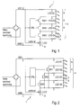
- FIGS. 1 and 2 Two possible implementations of an arrangement 1 for driving light-emitting diodes 5 according to the prior art are shown. Shown are so-called "direct AC LED” driver with four LED segments 6, which are designated by LED-S1 to LED-S4.
- the chain 4 is fed from the rectified mains voltage VDC 2, a ground side current source 8 ILED generating a constant current.
- the anode of the "upper" LED 5 of the segment LED-S1 6 is connected to the supply voltage VDC 2, ie the rectified mains voltage.
- Each segment 6 of the chain 4 has a first and a second terminal 7. In the FIG. 3 the first terminal of the first segment 6 is connected to the voltage VDC. The second terminal 7 of the first segment 6 is connected to the first terminal of the subsequent segment 6 of the chain 4. In addition, this second connection 7 is connected to a switching means 9, 10,.
- the entire LED chain 6 is connected via this switchable and disconnectable switching means 9, 10 of a common ground side power source 8 ILED powered.
- a common ground side power source 8 ILED powered.
- the current source 8 are for each current path n as switching means so-called cascode elements TC1 and TC2 9, 10, formed for example by MOSFETs, bipolar transistors or IGBTs.
- a cascode is the series connection of two transistors, the "lower” transistor (in the case of an n-channel or NPN) assuming control, while the "upper” transistor is used for increasing the dielectric strength and / or the output impedance.
- n stages are formed within the arrangement, which each comprise an n-th LED segment 6 and at least one n-th switching means 9 or 10.
- the first stage comprises the first segment 6 of the chain 4 as well as the first switching means 9.
- an element driving the first switching means 9 may also be included. In the example of FIG. 3 this is a first comparator or amplifier 11 AMP1.
- the cascode elements 9, 10 limit the voltage VQ across the current source 8 and absorb a portion of the difference between the instantaneous VDC and the forward voltage of the active segments 6 of the LED string 4.
- the gate or base voltage VGC applied to the cascode elements 9, 10 determines the maximum voltage VQ. For the automatic threshold adaptation, it is advantageous to keep this voltage low.
- the segment LED-S1 6 will first start to supply current when the forward voltage is reached. If the current limited by the current source 8 has been reached and VQ has reached the value limited by the cascode element 9, 10, the segment voltage VS1 increases as VDC 2 increases further while VQ remains approximately constant.
- comparator 11 With a hysteresis. This applies in particular to the case that relatively high-resistance MOSFETs are used as cascode elements 9, 10. When bipolar transistors are used, their base current must be limited.
- a gradual shutdown such as an amplifier or simple inverter, for example, with moderate gain instead of the comparator.
- the LED chain 4 consists of more than two segments 6, the process described is repeated with further increase of VDC 2 for the following stages or current paths n + 1, n + 2 ... etc.
- the chain 4 is not necessarily a cascode element 9, 10 is required, but it is circuitry advantageous for limiting the voltage VQ. This last cascode element 9, 10 does not have to be switched. In the FIG. 3 For example, two cascode elements 9 and 10 are shown.
- the cascode elements 9, 10 are activated again in the reverse order in accordance with the instantaneous voltage with the same circuit.
- the embodiment with similar segments 6 may be advantageous for the assembly of an application, but is not a prerequisite for the functionality of the method.
- the voltage drop VQ across the current source 8 has been neglected in the illustration for better understanding.
- a current path For the operation of an LED lamp on a dimmer which operates by means of a phase-gated (triac) or phase-section method (MOSFET or IGBT), a current path must be provided for charging a capacitor which determines the current flow angle within a half-wave of the mains voltage.
- triac phase-gated
- MOSFET phase-section method
- the previously described circuit 1 will only conduct current when the forward voltage of the first LED segment 6 has been reached and only then can the time-determining capacitor be charged. Without further measures, therefore, the maximum achievable with a dimmer current flow angle is reduced.
- This current is called “Bleeder Current”, since it is not used to drive the LEDs 5 itself.
- the circuit is off FIG. 4 by a cascode or switching element TCBL 16 and a comparator or amplifier 15 AMPBL have been extended according to the same principle.
- the "bleeder current” continues to flow until VDC has exceeded the forward voltage of segment LED-S1 6. In this case, the voltage VS1 rises and the comparator 15 AMPBL deactivates the "bleeder path". While TCBL 16 is active, the ILED 8 power source provides the bleeder current.
- a "high side” current source can be controlled by a ground-side or a potential-separated current sensor.
- VDC positive supply voltage
- GND negative supply
- a "high side” current source can be controlled by a ground-side or a potential-separated current sensor.
Abstract
Description
Die Erfindung betrifft eine Anordnung zur Ansteuerung von Leuchtdioden, mit einem Eingang, an welchen eine Eingangswechselspannung anlegbar ist und einer mit den Ausgängen der Anordnung zur Ansteuerung von Leuchtdioden verbundenen Kette von in einer Reihe geschalteten LEDs, welche in mindestens zwei Segmente unterteilt ist und wobei jedes Segment der Kette mit einem Ende zumindest mittelbar mit einer Konstantstromquelle verbunden ist.The invention relates to an arrangement for driving light-emitting diodes, having an input to which an input AC voltage can be applied and connected to the outputs of the arrangement for driving LEDs connected chain of series-connected LEDs, which is divided into at least two segments and each Segment of the chain is connected at one end at least indirectly connected to a constant current source.
Die Erfindung betrifft auch ein Verfahren zur Ansteuerung von Leuchtdioden, bei welchem eine Kette von in Reihe geschalteten Leuchtdioden bereitgestellt wird, welche in Segmente unterteilt ist, wobei jedes Segment mehrere Leuchtdioden beinhaltet und einen ersten Anschluss sowie einen zweiten Anschluss aufweist und wobei die Kette mit einer gleichgerichteten Eingangswechselspannung (VDC) betrieben wird.The invention also relates to a method for driving light-emitting diodes, in which a chain of light-emitting diodes connected in series is subdivided into segments, each segment comprising a plurality of light-emitting diodes and having a first terminal and a second terminal, and the chain having a rectified input AC voltage (VDC) is operated.
LEDs (LED = Light Emitting Diode, Leuchtdiode) werden zunehmend für Beleuchtungszwecke eingesetzt, da sie gegenüber herkömmlichen Leuchtmitteln wie Glühlampen oder Fluoreszenzlampen eine Reihe von Vorteilen, insbesondere einen geringeren Energiebedarf und eine längere Lebensdauer, aufweisen. Aufgrund ihrer halbleitertypischen Strom-Spannungscharakteristik ist es sinnvoll, LEDs mit einem Konstantstrom zu betreiben.LEDs (LED = Light Emitting Diode, LED) are increasingly used for lighting purposes, since they have a number of advantages over conventional bulbs such as incandescent or fluorescent lamps, in particular a lower energy consumption and a longer life. Due to their semiconductor-typical current-voltage characteristics, it makes sense to use LEDs with a Constant current to operate.
Beim Betrieb von Leuchtmitteln mit LEDs aus einem Lichtnetz sind daher schaltungstechnische Maßnahmen zu treffen, um aus einer versorgenden hohen Wechselspannung, welche beispielsweise 230 VAC betragen kann, den erforderlichen konstanten Gleichstrom mit der geringen Spannung von typischerweise 3 ... 4 V je LED zu erzeugen. Wobei diese Werte typischerweise für sogenannte weiße LEDs gelten und für andere LEDs abweichen können.When operating light sources with LEDs from a light network, therefore, circuit measures must be taken in order to produce the required constant direct current with the low voltage of typically 3... 4 V per LED from a supplying high alternating voltage, which may be for example 230 VAC , These values are typically valid for so-called white LEDs and may differ for other LEDs.
Neben dem verbreiteten Einsatz von sogenannten AC-DC-Konvertern, welche meist aus einem Gleichrichter und einem Schaltnetzteil bestehen, ist ein Verfahren bekannt, bei dem eine Kette von in Reihe geschalteten LEDs über eine oder mehrere lineare Stromquellen direkt aus der gleichgerichteten Wechselspannung angesteuert wird.In addition to the widespread use of so-called AC-DC converters, which usually consist of a rectifier and a switching power supply, a method is known in which a chain of LEDs connected in series is controlled via one or more linear current sources directly from the rectified AC voltage.
Diese Anordnung wird auch als "Direct AC LED" bezeichnet. Dazu kann vorteilhafterweise die LED-Kette in Segmente aufgeteilt werden, die entsprechend der momentanen Wechselspannung einzeln oder hintereinander geschaltet bestromt werden. Die Anzahl der in Reihe geschalteten LEDs und damit die Flussspannung der gesamten LED-Kette wird so ausgelegt, dass sie einem nennenswerten Anteil der Amplitude der Netzspannung entspricht, welcher beispielsweise im Bereich von 80 bis 90% der Amplitude der Netzspannung liegen kann.This arrangement is also referred to as "Direct AC LED". For this purpose, advantageously, the LED chain can be divided into segments, which are energized individually or in series according to the instantaneous AC voltage. The number of series-connected LEDs and thus the forward voltage of the entire LED chain is designed so that it corresponds to a significant proportion of the amplitude of the mains voltage, which may for example be in the range of 80 to 90% of the amplitude of the mains voltage.
Der Spannungsabfall über der linearen Stromquelle wird somit gering gehalten, was zu einem verhältnismäßig hohen Wirkungsgrad führt. Bei geringerer Momentanspannung wird nur ein Teil der LED-Kette, entsprechend der anordnungsseitigen Segmentierung der LEDs, ebenfalls mit relativ geringem Spannungsabfall über der zugehörigen Stromquelle angesteuert. Dadurch wird der Stromflusswinkel innerhalb einer halben Netzperiode vergrößert, was zu einer gleichmäßigeren Lichtabgabe führt. Optional kann der Strom der linearen Stromquelle oder Stromquellen entsprechend der momentanen Netzspannung moduliert werden, um den "Power Factor" zu erhöhen, d. h. den Oberwellengehalt des Versorgungsstroms gering zu halten.The voltage drop across the linear current source is thus kept low, resulting in a relatively high efficiency. At a lower instantaneous voltage, only a part of the LED chain, corresponding to the arrangement-side segmentation of the LEDs, is also driven with a relatively small voltage drop across the associated current source. As a result, the current flow angle is increased within half a grid period, resulting in a more even light emission leads. Optionally, the current of the linear current source or current sources may be modulated according to the instantaneous mains voltage to increase the "power factor", ie, to minimize the harmonic content of the supply current.
Vorteile dieses bekannten Verfahrens gegenüber der Verwendung von AC-DC Konvertern sind kleinere Bauform und geringere Kosten der Ansteuerelektronik sowie ein besseres EMV-Verhalten (EMV = elektro-magnetische Verträglichkeit) der Anordnung, da keine schnellen Schaltflanken auftreten.Advantages of this known method compared to the use of AC-DC converters are smaller design and lower costs of the control electronics and a better EMC behavior (EMC = electromagnetic compatibility) of the arrangement, since no fast switching edges occur.
Ein grundsätzlicher Nachteil besteht in der hohen Welligkeit der Lichtabgabe mit der doppelten Netzfrequenz, die von empfindlichen Personen als störend empfunden wird. Selbst bei einer konstanten Bestromung der LEDs reduziert sich die Lichtabgabe, wenn weniger Segmente, als in der LED-Kette angeordnet, aktiv sind.A fundamental disadvantage is the high waviness of the light output with twice the mains frequency, which is perceived by sensitive persons as disturbing. Even with a constant current supply to the LEDs, the light output is reduced if fewer segments than in the LED chain arranged, are active.
Wenn die Momentanspannung, mit welcher die LED-Ketten angesteuert werden, unter die Flussspannung des ersten Segments der Ketten absinkt, wird der Strom zu Null, d. h. in jeder Netzperiode gibt es zwei Lücken, in denen die LEDs nicht bestromt werden. Im Gegensatz zum Glühfaden einer Glühlampe, der eine erhebliche thermische Trägheit aufweist und damit die Welligkeit der zugeführten Leistung bedämpft, folgt die Lichtabgabe einer LED dem Strom praktisch verzögerungsfrei. Insbesondere diese Bestromungslücken können zu einem als unangenehm empfundenen Eindruck des "Flimmern" oder "Flackern" der Beleuchtung führen, welcher im englischen als "Flicker" bezeichnet wird.When the instantaneous voltage at which the LED strings are driven drops below the forward voltage of the first segment of the strings, the current becomes zero, i. H. There are two gaps in each grid period in which the LEDs are not energized. In contrast to the filament of an incandescent lamp, which has a considerable thermal inertia and thus attenuates the ripple of the supplied power, the light output of an LED follows the current virtually instantaneously. In particular, these energization gaps can lead to a perceived as unpleasant impression of "flicker" or "flicker" of the lighting, which is referred to in English as "flicker".
Ein weiterer schaltungstechnischer Nachteil der Ansteuerung besteht darin, dass die Umschaltschwellen der einzelnen Segmente an die Anzahl der LEDs je Segment und die tatsächliche Flussspannung angepasst werden müssen.Another circuit disadvantage of the control is that the switching thresholds of the individual segments must be adapted to the number of LEDs per segment and the actual forward voltage.
Somit besteht die Aufgabe der Erfindung darin, eine Anordnung und ein Verfahren zur Ansteuerung von Leuchtdioden anzugeben, womit eine verbesserte Ansteuerung der LEDs ohne eine Verschlechterung des Wirkungsgrades und/oder des Oberwellengehalts erreicht wird.Thus, the object of the invention is to provide an arrangement and a method for driving light-emitting diodes, whereby an improved control of the LEDs without deterioration of the efficiency and / or the harmonic content is achieved.
Außerdem soll eine automatische Anpassung der Umschaltschwellen zwischen den LED-Ketten an die Flusspannungen der Segmente der LED-Kette erreicht werden.In addition, an automatic adaptation of the switching thresholds between the LED chains to the flow voltages of the segments of the LED chain is to be achieved.
Die Schaltungsanordnungen mit den kennzeichnenden Merkmalen der Ansprüche 1 und 2 bieten den Vorteil einer gleichmäßigere Bestromung der LEDs in einer Kette sowie eine Verbesserung des Wirkungsgrads.The circuit arrangements with the characterizing features of
Die verfahrensseitige Lösung der vorliegenden Aufgabe ist mit den kennzeichnenden Merkmalen der Ansprüche 6 und 7 gezeigt.The procedural solution of the present task is shown with the characterizing features of
Durch die in den Unteransprüchen aufgeführten Maßnahmen sind vorteilhafte Weiterbildungen und Verbesserungen der in den Hauptansprüchen angegebenen Erfindung möglich.The measures listed in the dependent claims advantageous refinements and improvements of the invention specified in the main claims are possible.
Die Erfindung soll nachfolgend anhand eines Ausführungsbeispiels näher erläutert werden. In den zugehörigen Zeichnungen zeigt
- Fig. 1
- eine mögliche Ausführung einer Anordnung zur Ansteuerung von Leuchtdioden nach dem Stand der Technik in einer Variante als "Direct AC LED Drivers",
- Fig. 2
- eine andere mögliche Ausführung einer Anordnung zur Ansteuerung von Leuchtdioden nach dem Stand der Technik in einer Variante als "Direct AC LED Drivers",
- Fig. 3
- eine erfindungsgemäße Schaltungsanordnung zur Ansteuerung von Leuchtdioden mit einer automatischen Anpassung der Strompfade an die Flussspannung der LED Segmente,
- Fig. 4
- eine weitere erfindungsgemäße Schaltungsanordnung zur Ansteuerung von Leuchtdioden mit einer alternativen automatischen Anpassung mit gestuften Gate-Spannungen,
- Fig. 5
- eine Darstellung der Spannungsverläufe der gleichgerichteten Netzspannung und der Segmentspannungen über eine halbe Netzperiode und
- Fig. 6
- eine Schaltungsanordnung zur automatischen Steuerung eines "Bleeder Current".
- Fig. 1
- a possible embodiment of an arrangement for controlling light-emitting diodes according to the prior art in a variant as "Direct AC LED Drivers",
- Fig. 2
- another possible embodiment of an arrangement for driving light-emitting diodes according to the prior art in a variant as a "direct AC LED Drivers "
- Fig. 3
- a circuit arrangement according to the invention for controlling light-emitting diodes with an automatic adaptation of the current paths to the forward voltage of the LED segments,
- Fig. 4
- a further circuit arrangement according to the invention for driving light-emitting diodes with an alternative automatic adaptation with stepped gate voltages,
- Fig. 5
- a representation of the voltage waveforms of the rectified mains voltage and the segment voltages over half a grid period and
- Fig. 6
- a circuit arrangement for automatic control of a "Bleeder Current".
In der
In der Darstellung in
In der Ausgestaltung nach
Nachfolgend wird die erfindungsgemäße automatische Anpassung der Schaltschwellen an die Flussspannung der Segmente beschrieben.The automatic adaptation of the switching thresholds according to the invention to the forward voltage of the segments will be described below.
Die
Die Anode der "oberen" LED 5 des Segments LED-S1 6 ist mit der Versorgungsspannung VDC 2, d. h. der gleichgerichteten Netzspannung, verbunden. Jedes Segment 6 der Kette 4 weist einen ersten und einen zweiten Anschluss 7 auf. In der
Die gesamte LED-Kette 6 wird über diese zu- und abschaltbaren Schaltmittel 9, 10 von einer gemeinsamen masseseitigen Stromquelle 8 ILED gespeist. Oberhalb der Stromquelle 8 befinden sich für jeden Strompfad n als Schaltmittel sogenannte Kaskoden-Elemente TC1 und TC2 9, 10, gebildet beispielsweise durch MOSFETs, Bipolar-Transistoren oder IGBTs. Als Kaskode bezeichnet man die Hintereinanderschaltung zweier Transistoren, wobei der "untere" Transistor (bei n-Kanal oder NPN) die Steuerung übernimmt, während der "obere" Transistor zur Erhöhung der Spannungsfestigkeit und/oder der Ausgangsimpedanz dient.The
Derart werden n Stufen innerhalb der Anordnung ausgebildet, welche jeweils ein n-tes LED-Segment 6 und mindestens ein n-tes Schaltmittel 9 oder 10 umfassen. Die erste Stufe umfasst das erste Segment 6 der Kette 4 sowie das erste Schaltmittel 9. Zusätzlich kann auch noch ein das erste Schaltmittel 9 ansteuerndes Element beinhaltet sein. Im Beispiel der
Die Kaskoden-Elemente 9, 10 begrenzen die Spannung VQ über der Stromquelle 8 und nehmen einen Teil der Differenz zwischen momentaner VDC und der Flussspannung der aktiven Segmente 6 der LED-Kette 4 auf. Die an die Kaskoden-Elemente 9, 10 angelegte Gate- bzw. Basisspannung VGC bestimmt die maximale Spannung VQ. Für die automatische Schwellen-Adaption ist es vorteilhaft, diese Spannung niedrig zu halten.The
Steigt die Spannung VDC 2 von einem Wert kleiner als die Flussspannung des Segments LED-S1 6 beginnend an, so wird zunächst beim Erreichen der Flussspannung das Segment LED-S1 6 beginnen, Strom zu führen. Ist der durch die Stromquelle 8 begrenzte Strom erreicht und hat VQ den vom Kaskoden-Element 9, 10 begrenzten Wert erreicht, so steigt bei weiterer Erhöhung von VDC 2 die Segmentspannung VS1 an, während VQ annähernd konstant bleibt.If the
Zunächst fließt kein Strom durch das Segment LED-S2 6 und die Segmentspannung VS2 entspricht etwa der Spannung VQ. Erreicht VDC die Summe der Flussspannungen von LED-S1 6 und LED-S2 6, so beginnt auch LED-S2 6 zu leiten, und der Strom teilt sich zwischen TC1 9 und TC2 10 auf. Der Summenstrom wird weiterhin durch die gemeinsame Stromquelle 8 ILED bestimmt. Bei weiterer Erhöhung von VDC 2 steigt nun die Spannung VS2 gegenüber VQ an. Dieser Anstieg signalisiert, dass LED-S2 6 leitend ist und der Strompfad über TC1 9 abgeschaltet werden kann. Die Abschaltung kann beispielsweise über einen Verstärker oder Komparator 11 AMP erfolgen, dessen Vergleichswert um einen festlegbaren Betrag über der Spannung VQ liegt. Zur Vermeidung von Oszillationen um den Schaltpunkt ist es vorteilhaft, einen Komparator 11 mit einer Hysterese zu versehen. Dies gilt insbesondere für den Fall, dass als Kaskoden-Elemente 9, 10 relativ hochohmige MOSFETs verwendet werden. Bei Einsatz von Bipolartransistoren muss deren Basisstrom begrenzt werden.First, no current flows through the segment LED-
Vorteilhaft zur Vermeidung eventueller Störabstrahlung durch die Umschaltvorgänge ist eine graduelle Abschaltung, etwa durch einen Verstärker oder einfachen Inverter beispielsweise mit mäßiger Verstärkung anstelle des Komparators.Advantageous for avoiding possible noise radiation by the switching operations is a gradual shutdown, such as an amplifier or simple inverter, for example, with moderate gain instead of the comparator.
Eine Übernahme des Stroms durch TC2 10 ohne Schalten von TC1 9 ist ebenfalls möglich, indem eine Steuerspannung VG2 > VG1 angelegt wird, wie in der
Bei größerer Anzahl "n" von LED Segmenten kann dies zu einer erheblichen "Spreizung" der steuernden Gate-Spannungen VG1 bis VGn führen. Vorteilhaft ist daher die Kombination der gestuften Ansteuerspannungen mit dem Abschalten vorhergehender Strompfade.With larger numbers "n" of LED segments, this can lead to a significant "spread" of the controlling gate voltages VG1 to VGn. Advantageously, therefore, the combination of stepped drive voltages with the switching off of previous current paths.
Besteht die LED-Kette 4 aus mehr als zwei Segmenten 6, so wiederholt sich der beschriebene Vorgang bei weiterem Anstieg von VDC 2 für die folgenden Stufen oder Strompfade n+1, n+2 ... usw. Für das "letzte" Segment 6 der Kette 4 ist nicht unbedingt ein Kaskoden-Element 9, 10 erforderlich, es ist jedoch schaltungstechnisch vorteilhaft zur Begrenzung der Spannung VQ. Dieses letzte Kaskoden-Element 9, 10 muss nicht geschaltet werden. In der
Nachdem VDC 2 seine Amplitude überschritten hat und die Spannung wieder abfällt, werden mit derselben Schaltung die Kaskoden-Elemente 9, 10 in umgekehrter Reihenfolge entsprechend der momentanen Spannung wieder aktiviert.After
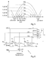
Die
Dieser Vorgang ist weiter dargestellt, bis alle Segmente 6 VLED-S1 bis VLED-S4 stromdurchflossen sind und leuchten. Nach dem Erreichen des Maximums der Spannung VDC 2 nimmt diese sinusförmig ab, was dazu führt, dass die Flussspannung des Segments VLED-S4 6 nicht mehr erreicht wird. Dies führt zur Unterbrechung des Stromflusses im Segment VLED-S4 6 und somit zu dessen Abschaltung. Nachfolgend werden nacheinander die Segmente VLED-S3 6, VLED-S2 6 und VLED-S1 6 abgeschalten, wodurch kein Strom mehr durch die Kette 4 fließt.This process is further illustrated until all
Die Ausführung mit gleichartigen Segmenten 6 kann vorteilhaft für die Bestückung einer Applikation sein, ist aber keine Voraussetzung für die Funktionalität des Verfahrens. Der Spannungsabfall VQ über der Stromquelle 8 wurde in der Darstellung zum besseren Verständnis vernachlässigt.The embodiment with
In den
Für den Betrieb einer LED-Leuchte an einem Dimmer, welcher mittels eines Phasenanschnitts- (Triac) oder Phasenabschnittsverfahrens (MOSFET oder IGBT) arbeitet, muss ein Strompfad zum Aufladen eines Kondensators, der den Stromflusswinkel innerhalb einer Halbwelle der Netzspannung bestimmt, bereitgestellt werden.For the operation of an LED lamp on a dimmer which operates by means of a phase-gated (triac) or phase-section method (MOSFET or IGBT), a current path must be provided for charging a capacitor which determines the current flow angle within a half-wave of the mains voltage.
Die zuvor beschriebene Schaltung 1 führt erst dann Strom, wenn die Flussspannung des ersten LED-Segments 6 erreicht ist und erst dann kann der zeitbestimmende Kondensator geladen werden. Ohne weitere Maßnahmen verringert sich daher der maximale mit einem Dimmer erreichbare Stromflusswinkel.The previously described
Um diese Verkürzung zu vermeiden, ist es vorteilhaft, einen zusätzlichen Strompfad einzurichten, der bereits aktiv ist, wenn die Netzspannung VDC noch kleiner als die Flussspannung des ersten Segments 6, beispielsweise LED-S1, ist.In order to avoid this shortening, it is advantageous to set up an additional current path which is already active when the mains voltage VDC is still lower than the forward voltage of the
Dieser Strom wird als "Bleeder Current" bezeichnet, da er nicht zur Ansteuerung der LEDs 5 selbst genutzt wird. In der
Die Polarität der beschriebenen Topologie kann umgedreht werden, d. h. die Stromquelle 8 liegt dann an der positiven Versorgungsspannung (VDC) 2 und die Katode der "untersten" LED 5 an der negativen Versorgung (GND). Ebenso gut kann eine "high side" Stromquelle durch einen masseseitigen oder auch durch einen potenzialgetrennten Stromfühler gesteuert werden.
Claims (9)
Priority Applications (7)
| Application Number | Priority Date | Filing Date | Title |
|---|---|---|---|
| EP13165730.6A EP2683220A1 (en) | 2012-07-04 | 2013-04-29 | Assembly and method for controlling light emitting diodes dependent on supply voltage amplitude, using shunting switch |
| TW102122086A TW201410070A (en) | 2012-07-04 | 2013-06-21 | Arrangement and method for driving light-emitting diodes |
| JP2015519169A JP2015525963A (en) | 2012-07-04 | 2013-07-01 | Apparatus and method for driving a plurality of light emitting diodes |
| CN201380035177.9A CN104604333A (en) | 2012-07-04 | 2013-07-01 | Arrangement and method for controlling light-emitting diodes in accordance with an input voltage level, by means of branch switches |
| US14/411,972 US20150156841A1 (en) | 2012-04-29 | 2013-07-01 | Arrangement and method for controlling light-emitting diodes in accordance with an input voltage level, by means of branch switches |
| KR1020157002844A KR20150036340A (en) | 2012-07-04 | 2013-07-01 | Arrangement and method for controlling light-emitting diodes in accordance with an input voltage level, by means of branch switches |
| PCT/EP2013/063809 WO2014005981A1 (en) | 2012-07-04 | 2013-07-01 | Arrangement and method for controlling light-emitting diodes in accordance with an input voltage level, by means of branch switches |
Applications Claiming Priority (3)
| Application Number | Priority Date | Filing Date | Title |
|---|---|---|---|
| EP12174995 | 2012-07-04 | ||
| DE102013100992 | 2013-01-31 | ||
| EP13165730.6A EP2683220A1 (en) | 2012-07-04 | 2013-04-29 | Assembly and method for controlling light emitting diodes dependent on supply voltage amplitude, using shunting switch |
Publications (1)
| Publication Number | Publication Date |
|---|---|
| EP2683220A1 true EP2683220A1 (en) | 2014-01-08 |
Family
ID=48325392
Family Applications (3)
| Application Number | Title | Priority Date | Filing Date |
|---|---|---|---|
| EP13165730.6A Withdrawn EP2683220A1 (en) | 2012-04-29 | 2013-04-29 | Assembly and method for controlling light emitting diodes dependent on supply voltage amplitude, using shunting switch |
| EP13169481.2A Withdrawn EP2683221A1 (en) | 2012-07-04 | 2013-05-28 | Assembly and method for controlling light emitting diodes dependent on supply voltage amplitude, using capacitor and switch |
| EP13172770.3A Withdrawn EP2683223A1 (en) | 2012-07-04 | 2013-06-19 | Method for controlling light emitting diodes, achieving AC load current in phase with AC supply voltage |
Family Applications After (2)
| Application Number | Title | Priority Date | Filing Date |
|---|---|---|---|
| EP13169481.2A Withdrawn EP2683221A1 (en) | 2012-07-04 | 2013-05-28 | Assembly and method for controlling light emitting diodes dependent on supply voltage amplitude, using capacitor and switch |
| EP13172770.3A Withdrawn EP2683223A1 (en) | 2012-07-04 | 2013-06-19 | Method for controlling light emitting diodes, achieving AC load current in phase with AC supply voltage |
Country Status (7)
| Country | Link |
|---|---|
| US (2) | US20150181666A1 (en) |
| EP (3) | EP2683220A1 (en) |
| JP (2) | JP2015525963A (en) |
| KR (2) | KR20150036340A (en) |
| CN (2) | CN104604333A (en) |
| TW (3) | TW201410070A (en) |
| WO (3) | WO2014005983A1 (en) |
Cited By (3)
| Publication number | Priority date | Publication date | Assignee | Title |
|---|---|---|---|---|
| DE102014200433A1 (en) * | 2014-01-13 | 2015-07-16 | Tridonic Jennersdorf Gmbh | Circuit arrangement for LED operating strands |
| WO2015117797A1 (en) * | 2014-02-10 | 2015-08-13 | Tridonic Gmbh & Co Kg | Voltage converter for operating luminaires |
| WO2016058585A1 (en) * | 2014-10-14 | 2016-04-21 | Atlas Elektronik Gmbh | Circuit for operating light-emitting diodes with low flicker, and luminous means and luminaire |
Families Citing this family (19)
| Publication number | Priority date | Publication date | Assignee | Title |
|---|---|---|---|---|
| US20150382409A1 (en) * | 2014-06-28 | 2015-12-31 | Microchip Technology Inc. | Sequential linear led driver utilizing headroom control |
| JP6403494B2 (en) * | 2014-08-26 | 2018-10-10 | シチズン時計株式会社 | LED drive circuit |
| US9445472B2 (en) * | 2014-09-23 | 2016-09-13 | Huizhou Light Engine Limited | Method and circuit for driving light-emitting diodes from three-phase power source |
| US10244596B2 (en) | 2014-10-14 | 2019-03-26 | Seoul Semiconductor Co., Ltd. | LED drive circuit having improved flicker performance and LED lighting device including the same |
| US9900944B2 (en) * | 2014-12-12 | 2018-02-20 | Rohm Co., Ltd. | Lighting device |
| TWI559811B (en) * | 2015-01-14 | 2016-11-21 | 立錡科技股份有限公司 | Light emitting device driver circuit and driving method of light emitting device circuit |
| TWI616115B (en) | 2015-02-12 | 2018-02-21 | Richtek Technology Corp | Linear light emitting diode driver and control method thereof |
| CN105992437A (en) * | 2015-02-13 | 2016-10-05 | 凹凸电子(武汉)有限公司 | Light source drive circuit and light source module |
| DE102015207144A1 (en) * | 2015-04-20 | 2016-10-20 | Osram Gmbh | Circuit arrangement for operating at least a first and a second LED string |
| WO2017015964A1 (en) * | 2015-07-30 | 2017-02-02 | Tridonic Gmbh & Co Kg | Direct ac driving circuit and luminaire |
| FR3039942B1 (en) * | 2015-08-03 | 2018-08-31 | Aledia | OPTOELECTRONIC CIRCUIT WITH ELECTROLUMINESCENT DIODES |
| TWM515620U (en) * | 2015-09-11 | 2016-01-11 | Luxmill Electronic Co Ltd | Multi-level LED driving circuit for eliminating undershoot |
| US9814105B2 (en) * | 2015-11-12 | 2017-11-07 | Semiconductor Components Industries, Llc | Control circuit for LED and active bleeder thereof |
| CN107801268B (en) * | 2016-08-31 | 2019-11-15 | 华润矽威科技(上海)有限公司 | Linear high-efficiency constant current is without stroboscopic LED driving circuit and driving method thereof |
| CN107148127B (en) * | 2017-07-21 | 2018-06-26 | 肖旭华 | A kind of method for detecting power supply or dimming light source performance to be measured automatically |
| TWI625987B (en) * | 2017-08-18 | 2018-06-01 | 鈺瀚科技股份有限公司 | An apparatus for driving leds using high voltage |
| CN111373468B (en) * | 2017-11-29 | 2022-10-28 | 平面系统公司 | Active discharge circuitry for display matrix |
| WO2020051036A1 (en) * | 2018-09-05 | 2020-03-12 | The Gillette Company Llc | Modulating an illumination level of a user interface luminous element |
| CN113455105A (en) * | 2018-12-17 | 2021-09-28 | 因特莱索有限责任公司 | AC driven light emitting diode system |
Citations (4)
| Publication number | Priority date | Publication date | Assignee | Title |
|---|---|---|---|---|
| US20100090609A1 (en) * | 2008-09-17 | 2010-04-15 | Superbulbs, Inc. | 3-way led bulb |
| US20100308739A1 (en) * | 2009-06-04 | 2010-12-09 | Exclara Inc. | Apparatus, Method and System for Providing AC Line Power to Lighting Devices |
| US20120081008A1 (en) * | 2010-10-05 | 2012-04-05 | Anwell Semiconductor Corp. | Control circuit module of light-emitting diode lamp |
| US20120081009A1 (en) * | 2009-06-04 | 2012-04-05 | Exclara Inc. | Apparatus, Method and System for Providing AC Line Power to Lighting Devices |
Family Cites Families (16)
| Publication number | Priority date | Publication date | Assignee | Title |
|---|---|---|---|---|
| US7081722B1 (en) * | 2005-02-04 | 2006-07-25 | Kimlong Huynh | Light emitting diode multiphase driver circuit and method |
| JP4588494B2 (en) * | 2005-03-03 | 2010-12-01 | 株式会社ジャムコ | Light emitting diode drive circuit for lighting |
| US7723926B2 (en) * | 2006-05-15 | 2010-05-25 | Supertex, Inc. | Shunting type PWM dimming circuit for individually controlling brightness of series connected LEDS operated at constant current and method therefor |
| WO2009060400A1 (en) * | 2007-11-07 | 2009-05-14 | Koninklijke Philips Electronics N.V. | Power supply circuit |
| JP2010109168A (en) * | 2008-10-30 | 2010-05-13 | Fuji Electric Systems Co Ltd | Led driving device, led driving method, and lighting device |
| US8174212B2 (en) * | 2008-11-30 | 2012-05-08 | Microsemi Corp.—Analog Mixed Signal Group Ltd. | LED string driver with light intensity responsive to input voltage |
| US8410717B2 (en) * | 2009-06-04 | 2013-04-02 | Point Somee Limited Liability Company | Apparatus, method and system for providing AC line power to lighting devices |
| US8384311B2 (en) * | 2009-10-14 | 2013-02-26 | Richard Landry Gray | Light emitting diode selection circuit |
| US8456095B2 (en) * | 2010-03-19 | 2013-06-04 | Active-Semi, Inc. | Reduced flicker AC LED lamp with separately shortable sections of an LED string |
| JP2012089827A (en) * | 2010-09-22 | 2012-05-10 | Citizen Holdings Co Ltd | Led driving circuit |
| KR20130129957A (en) * | 2010-10-24 | 2013-11-29 | 마이크로세미 코포레이션 | Synchronous regulation for led string driver |
| JP6029022B2 (en) * | 2010-12-15 | 2016-11-24 | フィリップス ライティング ホールディング ビー ヴィ | Linear driver with reduced perceived light flicker |
| JP5747656B2 (en) * | 2011-05-24 | 2015-07-15 | 日亜化学工業株式会社 | Light emitting diode drive device |
| JP5821279B2 (en) * | 2011-05-24 | 2015-11-24 | 日亜化学工業株式会社 | Light emitting diode drive device |
| JP2015506105A (en) * | 2011-12-16 | 2015-02-26 | ソウル セミコンダクター カンパニー リミテッド | LED drive device |
| US11178740B2 (en) * | 2011-12-27 | 2021-11-16 | Ideal Industries Lighting Llc | Solid-state lighting apparatus including current diversion controlled by lighting device bias states and current limiting using a passive electrical component |
-
2013
- 2013-04-29 EP EP13165730.6A patent/EP2683220A1/en not_active Withdrawn
- 2013-05-28 EP EP13169481.2A patent/EP2683221A1/en not_active Withdrawn
- 2013-06-19 EP EP13172770.3A patent/EP2683223A1/en not_active Withdrawn
- 2013-06-21 TW TW102122086A patent/TW201410070A/en unknown
- 2013-06-21 TW TW102122087A patent/TW201406197A/en unknown
- 2013-06-28 TW TW102123217A patent/TW201410071A/en unknown
- 2013-07-01 JP JP2015519169A patent/JP2015525963A/en active Pending
- 2013-07-01 WO PCT/EP2013/063811 patent/WO2014005983A1/en active Application Filing
- 2013-07-01 US US14/412,234 patent/US20150181666A1/en not_active Abandoned
- 2013-07-01 US US14/411,972 patent/US20150156841A1/en not_active Abandoned
- 2013-07-01 CN CN201380035177.9A patent/CN104604333A/en active Pending
- 2013-07-01 KR KR1020157002844A patent/KR20150036340A/en not_active Application Discontinuation
- 2013-07-01 JP JP2015519168A patent/JP2015525962A/en active Pending
- 2013-07-01 WO PCT/EP2013/063808 patent/WO2014005980A1/en active Application Filing
- 2013-07-01 KR KR1020157003077A patent/KR20150036392A/en not_active Application Discontinuation
- 2013-07-01 CN CN201380035557.2A patent/CN104584687A/en active Pending
- 2013-07-01 WO PCT/EP2013/063809 patent/WO2014005981A1/en active Application Filing
Patent Citations (4)
| Publication number | Priority date | Publication date | Assignee | Title |
|---|---|---|---|---|
| US20100090609A1 (en) * | 2008-09-17 | 2010-04-15 | Superbulbs, Inc. | 3-way led bulb |
| US20100308739A1 (en) * | 2009-06-04 | 2010-12-09 | Exclara Inc. | Apparatus, Method and System for Providing AC Line Power to Lighting Devices |
| US20120081009A1 (en) * | 2009-06-04 | 2012-04-05 | Exclara Inc. | Apparatus, Method and System for Providing AC Line Power to Lighting Devices |
| US20120081008A1 (en) * | 2010-10-05 | 2012-04-05 | Anwell Semiconductor Corp. | Control circuit module of light-emitting diode lamp |
Cited By (6)
| Publication number | Priority date | Publication date | Assignee | Title |
|---|---|---|---|---|
| DE102014200433A1 (en) * | 2014-01-13 | 2015-07-16 | Tridonic Jennersdorf Gmbh | Circuit arrangement for LED operating strands |
| EP3095301A1 (en) * | 2014-01-13 | 2016-11-23 | Tridonic Jennersdorf GmbH | A circuit arrangement for operating led strings |
| EP3095301B1 (en) * | 2014-01-13 | 2023-03-08 | Tridonic GmbH & Co. KG | A circuit arrangement for operating led strings |
| WO2015117797A1 (en) * | 2014-02-10 | 2015-08-13 | Tridonic Gmbh & Co Kg | Voltage converter for operating luminaires |
| US9814113B2 (en) | 2014-02-10 | 2017-11-07 | Tridonic Gmbh & Co Kg | Voltage converter for operating lamps |
| WO2016058585A1 (en) * | 2014-10-14 | 2016-04-21 | Atlas Elektronik Gmbh | Circuit for operating light-emitting diodes with low flicker, and luminous means and luminaire |
Also Published As
| Publication number | Publication date |
|---|---|
| WO2014005980A1 (en) | 2014-01-09 |
| CN104604333A (en) | 2015-05-06 |
| JP2015525962A (en) | 2015-09-07 |
| CN104584687A (en) | 2015-04-29 |
| KR20150036392A (en) | 2015-04-07 |
| EP2683223A1 (en) | 2014-01-08 |
| TW201410070A (en) | 2014-03-01 |
| TW201406197A (en) | 2014-02-01 |
| KR20150036340A (en) | 2015-04-07 |
| JP2015525963A (en) | 2015-09-07 |
| TW201410071A (en) | 2014-03-01 |
| US20150156841A1 (en) | 2015-06-04 |
| WO2014005981A1 (en) | 2014-01-09 |
| EP2683221A1 (en) | 2014-01-08 |
| US20150181666A1 (en) | 2015-06-25 |
| WO2014005983A1 (en) | 2014-01-09 |
Similar Documents
| Publication | Publication Date | Title |
|---|---|---|
| EP2683220A1 (en) | Assembly and method for controlling light emitting diodes dependent on supply voltage amplitude, using shunting switch | |
| DE102010001919B4 (en) | Circuit and method for controlling a light source | |
| DE202012013514U1 (en) | Illumination device with semiconductor light-emitting diodes | |
| WO2010046065A1 (en) | Operating circuit for leds | |
| DE202015009356U1 (en) | AC powered lighting device with light emitting element | |
| WO2011083117A2 (en) | Combined method for operating an electric illuminant and operating circuit | |
| DE212015000247U1 (en) | LED drive circuit with improved flicker performance and LED lighting device containing this | |
| DE102013113053A1 (en) | Driver circuit with a semiconductor light source and method for operating a driver circuit | |
| AT17197U1 (en) | Color-adjustable LED module with anti-parallel LED chains | |
| DE102010015125A1 (en) | Method for controlling a luminous flux of a lighting device with a number of semiconductor illuminants, which is set up for the identification and marking of traffic areas of airports | |
| DE102010039827B4 (en) | Method for operating at least one light emitting diode and lighting device for carrying out the method | |
| WO2014114486A2 (en) | Arrangement and method for operating an arrangement | |
| AT12464U1 (en) | OPERATING CIRCUIT FOR LIGHT DIODES | |
| AT12495U1 (en) | ERROR DETECTION FOR LUMINAIRE DIODES | |
| DE102011003937A1 (en) | Control circuit for controlling lamps switched into series, has electronic switches arranged parallel to lamps and short circuited during activation of lamps that are switched into series and comprise common reference potential | |
| EP3370484B1 (en) | Light emitting diode circuit and luminaire | |
| EP3363265B1 (en) | Circuit for operating light-emitting diodes having low flicker, and lighting means and lamp | |
| DE112014006816T5 (en) | Adaptive power compensation in LED lamps | |
| EP2187707B1 (en) | Switching device for controlling organic LEDs | |
| EP3207767B1 (en) | Circuit for operating light-emitting diodes with low flicker, and luminous means and luminaire | |
| DE102014104365A1 (en) | lighting device | |
| EP3449692A1 (en) | Method for controlling an led module | |
| WO2010121925A1 (en) | Lighting apparatus having a lighting function that can be varied over time | |
| EP3286988A1 (en) | Circuit arrangement for operating at least one first and one second led strand | |
| DE102014005584B4 (en) | LED lighting device with an energy storage module and method for operating the LED lighting device |
Legal Events
| Date | Code | Title | Description |
|---|---|---|---|
| PUAI | Public reference made under article 153(3) epc to a published international application that has entered the european phase |
Free format text: ORIGINAL CODE: 0009012 |
|
| AK | Designated contracting states |
Kind code of ref document: A1 Designated state(s): AL AT BE BG CH CY CZ DE DK EE ES FI FR GB GR HR HU IE IS IT LI LT LU LV MC MK MT NL NO PL PT RO RS SE SI SK SM TR |
|
| AX | Request for extension of the european patent |
Extension state: BA ME |
|
| 17P | Request for examination filed |
Effective date: 20140708 |
|
| RBV | Designated contracting states (corrected) |
Designated state(s): AL AT BE BG CH CY CZ DE DK EE ES FI FR GB GR HR HU IE IS IT LI LT LU LV MC MK MT NL NO PL PT RO RS SE SI SK SM TR |
|
| STAA | Information on the status of an ep patent application or granted ep patent |
Free format text: STATUS: THE APPLICATION IS DEEMED TO BE WITHDRAWN |
|
| 18D | Application deemed to be withdrawn |
Effective date: 20161101 |