EP2682581A1 - Exhaust emission control apparatus for internal combustion engine, and control method for the exhaust emission control apparatus - Google Patents
Exhaust emission control apparatus for internal combustion engine, and control method for the exhaust emission control apparatus Download PDFInfo
- Publication number
- EP2682581A1 EP2682581A1 EP20130173371 EP13173371A EP2682581A1 EP 2682581 A1 EP2682581 A1 EP 2682581A1 EP 20130173371 EP20130173371 EP 20130173371 EP 13173371 A EP13173371 A EP 13173371A EP 2682581 A1 EP2682581 A1 EP 2682581A1
- Authority
- EP
- European Patent Office
- Prior art keywords
- recovery process
- urea water
- emission control
- control apparatus
- exhaust emission
- Prior art date
- Legal status (The legal status is an assumption and is not a legal conclusion. Google has not performed a legal analysis and makes no representation as to the accuracy of the status listed.)
- Withdrawn
Links
Images


Classifications
-
- F—MECHANICAL ENGINEERING; LIGHTING; HEATING; WEAPONS; BLASTING
- F01—MACHINES OR ENGINES IN GENERAL; ENGINE PLANTS IN GENERAL; STEAM ENGINES
- F01N—GAS-FLOW SILENCERS OR EXHAUST APPARATUS FOR MACHINES OR ENGINES IN GENERAL; GAS-FLOW SILENCERS OR EXHAUST APPARATUS FOR INTERNAL-COMBUSTION ENGINES
- F01N3/00—Exhaust or silencing apparatus having means for purifying, rendering innocuous, or otherwise treating exhaust
- F01N3/08—Exhaust or silencing apparatus having means for purifying, rendering innocuous, or otherwise treating exhaust for rendering innocuous
- F01N3/10—Exhaust or silencing apparatus having means for purifying, rendering innocuous, or otherwise treating exhaust for rendering innocuous by thermal or catalytic conversion of noxious components of exhaust
- F01N3/18—Exhaust or silencing apparatus having means for purifying, rendering innocuous, or otherwise treating exhaust for rendering innocuous by thermal or catalytic conversion of noxious components of exhaust characterised by methods of operation; Control
- F01N3/20—Exhaust or silencing apparatus having means for purifying, rendering innocuous, or otherwise treating exhaust for rendering innocuous by thermal or catalytic conversion of noxious components of exhaust characterised by methods of operation; Control specially adapted for catalytic conversion
- F01N3/206—Adding periodically or continuously substances to exhaust gases for promoting purification, e.g. catalytic material in liquid form, NOx reducing agents
- F01N3/208—Control of selective catalytic reduction [SCR], e.g. by adjusting the dosing of reducing agent
-
- F—MECHANICAL ENGINEERING; LIGHTING; HEATING; WEAPONS; BLASTING
- F01—MACHINES OR ENGINES IN GENERAL; ENGINE PLANTS IN GENERAL; STEAM ENGINES
- F01N—GAS-FLOW SILENCERS OR EXHAUST APPARATUS FOR MACHINES OR ENGINES IN GENERAL; GAS-FLOW SILENCERS OR EXHAUST APPARATUS FOR INTERNAL-COMBUSTION ENGINES
- F01N2610/00—Adding substances to exhaust gases
- F01N2610/02—Adding substances to exhaust gases the substance being ammonia or urea
-
- F—MECHANICAL ENGINEERING; LIGHTING; HEATING; WEAPONS; BLASTING
- F01—MACHINES OR ENGINES IN GENERAL; ENGINE PLANTS IN GENERAL; STEAM ENGINES
- F01N—GAS-FLOW SILENCERS OR EXHAUST APPARATUS FOR MACHINES OR ENGINES IN GENERAL; GAS-FLOW SILENCERS OR EXHAUST APPARATUS FOR INTERNAL-COMBUSTION ENGINES
- F01N2610/00—Adding substances to exhaust gases
- F01N2610/14—Arrangements for the supply of substances, e.g. conduits
- F01N2610/1493—Purging the reducing agent out of the conduits or nozzle
-
- F—MECHANICAL ENGINEERING; LIGHTING; HEATING; WEAPONS; BLASTING
- F01—MACHINES OR ENGINES IN GENERAL; ENGINE PLANTS IN GENERAL; STEAM ENGINES
- F01N—GAS-FLOW SILENCERS OR EXHAUST APPARATUS FOR MACHINES OR ENGINES IN GENERAL; GAS-FLOW SILENCERS OR EXHAUST APPARATUS FOR INTERNAL-COMBUSTION ENGINES
- F01N2900/00—Details of electrical control or of the monitoring of the exhaust gas treating apparatus
- F01N2900/06—Parameters used for exhaust control or diagnosing
- F01N2900/10—Parameters used for exhaust control or diagnosing said parameters being related to the vehicle or its components
- F01N2900/104—Battery status
-
- Y—GENERAL TAGGING OF NEW TECHNOLOGICAL DEVELOPMENTS; GENERAL TAGGING OF CROSS-SECTIONAL TECHNOLOGIES SPANNING OVER SEVERAL SECTIONS OF THE IPC; TECHNICAL SUBJECTS COVERED BY FORMER USPC CROSS-REFERENCE ART COLLECTIONS [XRACs] AND DIGESTS
- Y02—TECHNOLOGIES OR APPLICATIONS FOR MITIGATION OR ADAPTATION AGAINST CLIMATE CHANGE
- Y02A—TECHNOLOGIES FOR ADAPTATION TO CLIMATE CHANGE
- Y02A50/00—TECHNOLOGIES FOR ADAPTATION TO CLIMATE CHANGE in human health protection, e.g. against extreme weather
- Y02A50/20—Air quality improvement or preservation, e.g. vehicle emission control or emission reduction by using catalytic converters
-
- Y—GENERAL TAGGING OF NEW TECHNOLOGICAL DEVELOPMENTS; GENERAL TAGGING OF CROSS-SECTIONAL TECHNOLOGIES SPANNING OVER SEVERAL SECTIONS OF THE IPC; TECHNICAL SUBJECTS COVERED BY FORMER USPC CROSS-REFERENCE ART COLLECTIONS [XRACs] AND DIGESTS
- Y02—TECHNOLOGIES OR APPLICATIONS FOR MITIGATION OR ADAPTATION AGAINST CLIMATE CHANGE
- Y02T—CLIMATE CHANGE MITIGATION TECHNOLOGIES RELATED TO TRANSPORTATION
- Y02T10/00—Road transport of goods or passengers
- Y02T10/10—Internal combustion engine [ICE] based vehicles
- Y02T10/12—Improving ICE efficiencies
Definitions
- the invention relates to an exhaust emission control apparatus for an internal combustion engine and a control method for the exhaust emission control apparatus.
- exhaust emission control apparatuses that add a liquid-form additive into an exhaust passageway for the purpose of removal of nitrogen oxides (NOx) in exhaust gas, regeneration of an exhaust emission control catalyst, etc. have been put into practical use.
- a known example of such exhaust emission control apparatuses is a urea-SCR (Selective Catalytic Reduction) system exhaust emission control apparatus that uses urea ((NH 2 ) 2 CO) water as a reducing agent.
- urea ((NH 2 ) 2 CO) water as a reducing agent.
- an addition valve for adding urea water is disposed on the exhaust passageway, and the addition valve is supplied with urea water from a urea water tank through a supply passageway.
- a support that supports an SCR catalyst at a downstream side of the addition valve in the direction of exhaust flow.
- urea water is added into the exhaust passageway from the addition valve.
- the urea water added into the exhaust passageway is thermally decomposed or hydrolyzed in exhaust gas to change into ammonia (NH 3 ).
- ammonia and NOx present in exhaust gas react with each other on the SCR catalyst.
- Nox in exhaust gas decomposes into water and nitrogen (N 2 ), which is harmless.
- the additive is not added during stop of the engine, or the like. Therefore, the additive remains in the addition valve and the supply passageway. Then, if the remaining additive freezes and therefore expands in volume during a cold state of the internal combustion engine or the like, there is possibility of breakage of the addition valve or the supply passageway.
- the execution time of the recovery process is set at a constant time. Therefore, if the battery voltage of a vehicle in which an internal combustion engine is mounted drops, the pump's driving capability decreases, so that the amount of recovery of the additive, such as urea water as mentioned above or the like, reduces. Hence, there is possibility of failing to sufficiently recover the additive remaining in the supply passageway or the like.
- the invention provides an exhaust emission control apparatus for an internal combustion engine and a control method for the exhaust emission control apparatus which are capable of precisely recovering an additive remaining in an addition valve or a supply passageway that supplies the additive to the addition valve.
- An exhaust emission control apparatus for an internal combustion engine in accordance with a first aspect of the invention includes an addition valve provided in an exhaust passageway of the internal combustion engine and a supply passageway that supplies a liquid-form additive to the addition valve, and executes a recovery process of recovering the additive present in the supply passageway by driving an electric pump with a vehicle-mounted battery after the internal combustion engine stops.
- execution time of the recovery process is variably set based on battery voltage of the vehicle-mounted battery.
- the execution time of the recovery process is variably set on the basis of the battery voltage of the vehicle-mounted battery.
- the execution time of the recovery process can be set according to the driving capability of the electric pump. Therefore, the additive remaining in the addition valve or the supply passageway can be precisely recovered by the recovery process.
- the execution time of the recovery process may be set longer as the battery voltage is lower.
- the execution time of the recovery process is longer as the battery voltage is lower, the execution time of the recovery process can be made longer in accordance with decrease in the driving capability of the pump. Therefore, shortage in the driving capability of the pump can be compensated for by increase in the execution time of the recovery process. Therefore, the additive remaining in the supply passageway can be sufficiently recovered.
- the execution time of the recovery process can be made short. Therefore, it is possible to restrain the pump from being driven more than necessary after the remaining urea water is recovered. Furthermore, the electric power consumption of the battery during stop of the engine can be reduced.
- the execution time of the recovery process may be variably set when the battery voltage is less than or equal to a predetermined value.
- the additive may be urea water, and a nitrogen oxide in exhaust gas may be removed through a selective catalyst reduction, using the urea water as a reducing agent.
- a control method for an exhaust emission control apparatus for an internal combustion engine in accordance with a second aspect of the invention is a control method for an exhaust emission control apparatus for an internal combustion engine which includes an addition valve provided in an exhaust passageway of the internal combustion engine and a supply passageway that supplies a liquid-form additive to the addition valve and which executes a recovery process of recovering the additive present in the supply passageway by driving an electric pump with a vehicle-mounted battery after the internal combustion engine stops.
- execution time of the recovery process is variably set based on battery voltage of the vehicle-mounted battery.
- This aspect of the invention may be applied to a urea-SCR-system exhaust emission control apparatus that adds urea water as an additive.
- an exhaust passageway 1 of the internal combustion engine is provided with a urea water supply device 100.
- the urea water supply device 100 supplies urea water into the exhaust passageway 1.
- the urea water supply device 100 is provided with a urea water tank 101.
- Urea ((NH 2 ) 2 CO) water is stored in the urea water tank 101.
- a supply passageway 102 is connected to the urea water tank 101. Specifically, an end portion of the supply passageway 102 is connected to the urea water tank 101.
- the supply passageway 102 is a passageway for delivering urea water.
- a urea water pump 103 is disposed within the urea water tank 101.
- the urea water pump 103 is an electric pump to which voltage from a battery 2 mounted in the vehicle is applied and therefore which is driven by the voltage from the battery 2.
- urea water is pressurized and discharged from the urea water tank 101 into the supply passageway 102.
- Another end portion of the supply passageway 102 is connected to a urea water addition valve 104.
- the urea water addition valve 104 is disposed on the exhaust passageway 1.
- the urea water addition valve 104 sprays urea water pumped through the supply passageway 102 into the exhaust passageway 1, according to the opening of the urea water addition valve 104.
- a catalytic converter 3 is disposed downstream of the urea water addition valve 104 in the exhaust passageway 1 in the exhaust flow direction.
- an SCR catalyst support 4 supports a urea-SCR catalyst.
- the ASC catalyst support 5 supports an ammonia slip restraining catalyst (hereinafter, referred to as ASC catalyst).
- the SCR catalyst support 4 and the ASC catalyst support 5 are each made of a ceramic material or the like, and are formed in a cylindrical shape whose interior has a honeycomb structure.
- an accelerator sensor 6, a brake sensor 7, a vehicle speed sensor 8, an ignition switch 9, etc. are provided.
- the accelerator sensor 6 detects the amount of depression of an accelerator pedal.
- the brake sensor 7 detects the amount of brake operation.
- the vehicle speed sensor 8 detects the vehicle speed of the vehicle.
- the ignition switch 9 detects an engine starting operation and an engine stop operation of an internal combustion engine performed by a driver of the vehicle.
- the electronic control unit 10 is constructed mainly of a microcomputer that includes a central processing control unit (CPU), a read-only memory (ROM), a random access memory (RAM), a timer counter, input interfaces, output interfaces, etc.
- the read-only memory pre-stores various programs, maps, etc.
- the random access memory temporarily stores computation results provided by the CPU.
- the electronic control unit 10 is supplied with electric power from the battery 2 mounted in the vehicle. Furthermore, the battery 2 supplies electric power not only to the electronic control unit 10 and the urea water pump 103 but also to electric appliances and the like 11 that are mounted in the vehicle.
- the electric appliances and the like 11 are, for example, lamps, an audio system, etc.
- the electronic control unit 10 performs a control of addition of urea water performed by the urea water addition valve 104 as an exhaust emission control.
- an exact amount of urea water to be added is calculated on the basis of the engine operation state and the like in order to obtain reduction processes of NOx in exhaust gas.
- the open valve state of the urea water addition valve 104 is controlled so that the calculated amount of addition of urea water is injected from the urea water addition valve 104.
- the addition of urea water for reduction of NOx continues to be performed during operation of the engine, and is stopped when operation of the engine is stopped.
- urea water remaining in the urea water addition valve 104 or the supply passageway 102 freezes and expands in volume. This may break or damage the urea water addition valve 104 or the supply passageway 102.
- the electronic control unit 10 performs a recovery process.
- the recovery process is a process in which urea water remaining in the supply passageway 102 is recovered into the urea water tank 101 by reversely turning the urea water pump 103 during stop of the engine.
- the execution time of the recovery process is variably set on the basis of the battery voltage. That is, the execution time of the recovery process is set according to the battery voltage. Due to this, the recovery process is precisely executed according to the driving capability of urea water pump 103.
- This recovery process is executed by the electronic control unit 10 only once after the engine is stopped.
- step S1 it is firstly determined whether the engine has been stopped (step S1). Incidentally, this determination can be performed on the basis of the signal from the ignition switch 9. If it is determined that the engine has stopped (YES in step S1), the process subsequently proceeds to step S2.
- step S2 information about the battery voltage of the vehicle-mounted battery 2 is acquired. Incidentally, the battery voltage may be calculated by the electronic control unit 10, which is fed with electricity from the battery 2. It is also permissible to provide a voltage sensor or the like for providing information about the battery voltage.
- step S3 a set time ⁇ of the recovery process which corresponds to the battery voltage is computed from a map. The map is stored beforehand in the electronic control unit 10. An example of a correspondence relation between the set time ⁇ of the recovery process and the battery voltage is shown in FIG. 3 .
- the set time ⁇ of the recovery process is set so as to be longer as the battery voltage is lower.
- the execution time of the recovery process necessary to recover the remaining urea water is set corresponding to the battery voltage.
- the execution time of the recovery process necessary to recover the remaining urea water is set corresponding to the driving capability of the electric urea water pump 103.
- the map is prepared beforehand through an experiment or the like.
- step S4 the process of recovering urea water is executed (step S4).
- the electric urea water pump 103 is driven in the reverse direction to discharge urea water from the supply passageway 102 into the urea water tank 101.
- the supply passageway 102 and the urea water addition valve 104 are in communication with each other. Therefore, as the urea water in the supply passageway 102 is discharged by the recovery process, the urea water remaining in the urea water addition valve 104 is also recovered.
- step S5 the elapsed time Tq following the start of the recovery process is counted.
- step S6 it is determined whether the elapsed time Tq thus counted is longer than or equal to the set time ⁇ (step S6). If in this determination process, it is determined that the elapsed time Tq is less than the set time ⁇ (NO in step S6), the process of step S5 and step S6 is repeated. On the other hand, if it is determined that the elapsed time Tq is longer than or equal to the set time ⁇ (YES in step S6), the process proceeds to step S7, in which the recovery process is ended.
- the execution time of the recovery process is set at the set time ⁇ that is calculated according to the battery voltage.
- the execution time of the recovery process is variably set on the basis of the battery voltage.
- the set time ⁇ of the recovery process is set at a greater value as the battery voltage of the vehicle-mounted battery 2 is lower; and the recovery process is executed until the execution time of the recovery process is equal to or greater than the set time ⁇ .
- the execution time of the recovery process is set longer as the battery voltage is lower. Therefore, the execution time of the recovery process can be made longer in accordance with decline in the driving capability of the electric urea water pump 103.
- the additive remaining in the supply passageway 102 can be precisely recovered. Therefore, breakage of the urea water addition valve 104 or the supply passageway 102 can be restrained.
- the execution time of the recovery process is set short. Therefore, it is possible to restrain the occurrence of an event in which the urea water pump 103 is driven more than necessary after the urea water remaining is recovered, and it is also possible to reduce the electric power consumption during stop of the engine.
- FIGS. 4 and 5 An embodiment in which an exhaust emission control apparatus for an internal combustion engine in accordance with the invention is embodied will be described with reference to FIGS. 4 and 5 .
- This embodiment is different from the foregoing embodiment in the manner of setting the execution time of the recovery process.
- constructions of the embodiment that are substantially the same as those of the foregoing embodiment will be denoted by the same characters, and detailed descriptions thereof will be omitted.
- the execution time of the recovery process is variably set.
- steps S1 and S2 and steps S4 to S6 are substantially the same as in the foregoing embodiment.
- the recovery process in this embodiment is also a process that is executed by the electronic control unit 10 only once after the engine is stopped.
- step S1 it is firstly determined whether the engine has been stopped (step S1). If it is determined that the engine has been stopped (YES in step S1), the process subsequently proceeds to step S2. In step S2, information about the battery voltage of the vehicle-mounted battery 2 is acquired. Next, in step S8, it is determined whether the calculated battery voltage is less than or equal to a predetermined value Vb.
- the predetermined value Vb has been set at a maximum value of the battery voltage at which the urea water remaining in the supply passageway 102 cannot be sufficiently recovered if the recovery process for urea water is executed for a standard time ⁇ 0.
- the set time ⁇ of the recovery process is set at the standard time ⁇ 0 (step S10). Specifically, if it is determined that when the recovery process is executed at the calculated battery voltage for the standard time ⁇ 0, the urea water remaining in the supply passageway 102 can be sufficiently recovered, the abnormality determination value ⁇ of the recovery process is set at the standard time ⁇ 0.
- the standard time ⁇ 0 is an execution time that is set for the recovery process during a usual state.
- the standard time ⁇ 0 is, for example, an amount of time determined beforehand according to the capacity of the urea water addition valve 104 or the supply passageway 102, or the like.
- the set time ⁇ of the recovery process is computed according to the battery voltage from the map (step S9).
- the set time ⁇ of the recovery process is computed according to the battery voltage, from the map.
- the map is stored beforehand in the electronic control unit 10.
- the set time ⁇ is set longer than the standard time ⁇ 0 ( ⁇ > ⁇ 0).
- the set time ⁇ is set longer as the battery voltage is lower.
- step S4 the recovery process for urea water is executed (step S4). Subsequently, the elapsed time Tq following the start of the recovery process is counted (step S5).
- step S6 it is determined whether the thus-counted elapsed time Tq is greater than or equal to the set time ⁇ (step S6). If in this process, it is determined that the elapsed time Tq is less than the set time ⁇ (NO in step S6), the process of steps S5 and S6 is repeated. On the other hand, if it is determined that the elapsed time Tq is greater than or equal to the set time ⁇ (YES in step S6), the process proceeds to step S7, in which the recovery process ends.
- the execution time of the recovery process is set at the standard time ⁇ 0.
- the execution time is set longer as the battery voltage is lower. In this manner, in the embodiment, when the battery voltage is less than or equal to the predetermined value Vb, the execution time of the recovery process is set longer than the standard time ⁇ 0.
- the following advantageous effects can be obtained.
- the execution time of the recovery process is set longer than the standard time ⁇ 0. Therefore, in the case where urea water cannot sufficiently be recovered within the usually set execution time, the execution time of the recovery process can be made longer. Therefore, the urea water remaining in the supply passageway 102 can be precisely recovered.
- the execution time of the recovery process is set longer as the battery voltage is lower. Therefore, the execution time of the recovery process can be increased in accordance with decrease in the driving capability of the electric urea water pump 103, the urea water remaining in the supply passageway 102 can be precisely recovered.
- the foregoing embodiments can also be carried out with modifications as follows.
- the execution time of the recovery process in the case where the battery voltage is greater than the predetermined value Vb, the execution time of the recovery process is set at the standard time ⁇ 0, and in the case where the battery voltage is less than or equal to the predetermined value Vb, the execution time of the recovery process is set longer as the battery voltage is lower.
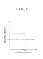
- the manner of setting the execution time of the recovery process is not limited to the foregoing manner. An example of a different manner of setting the execution time is shown in FIG. 6 .
- the execution time of the recovery process when the battery voltage is greater than the predetermined value Vb, the execution time of the recovery process may be set at the standard time ⁇ 0, and when the battery voltage is less than or equal to the predetermined value Vb, the execution time of the recovery process may be set at a predetermined time ⁇ 1 ( ⁇ 1 > ⁇ 0). Furthermore, instead of setting two different values of time, that is, the standard time ⁇ 0 and the predetermined time ⁇ 1, the execution time of the recovery process may be set at three or more different values of time. Such a construction, too, is able to achieve an advantageous effect similar to the effect described in (2) above.
- the manner of setting the execution time of the recovery process is not limited to foregoing manner.
- the battery voltage may be constantly monitored, and during execution of the recovery process, the execution time of the recovery process may be changed according to change in the battery voltage, during execution of the recovery process. This arrangement also makes it possible to precisely recover the urea water remaining.
- the determination as to whether the engine has been stopped is carried out on the basis of the signal from the ignition switch 9, the determination may instead be carried out on the basis of a detected value from a different sensor, for example, the crank angle sensor, or the like.
- the invention is embodied in the exhaust emission control apparatus that supplies urea water as an additive.
- the additive employed may also be a reducing agent other than urea water.
- the invention may be applied to an apparatus that adds ammonia water, fuel, etc.
Landscapes
- Chemical & Material Sciences (AREA)
- Engineering & Computer Science (AREA)
- Chemical Kinetics & Catalysis (AREA)
- Health & Medical Sciences (AREA)
- Toxicology (AREA)
- Combustion & Propulsion (AREA)
- Mechanical Engineering (AREA)
- General Engineering & Computer Science (AREA)
- Exhaust Gas After Treatment (AREA)
- Combined Controls Of Internal Combustion Engines (AREA)
Abstract
Description
- The invention relates to an exhaust emission control apparatus for an internal combustion engine and a control method for the exhaust emission control apparatus.
- In recent years, exhaust emission control apparatuses that add a liquid-form additive into an exhaust passageway for the purpose of removal of nitrogen oxides (NOx) in exhaust gas, regeneration of an exhaust emission control catalyst, etc. have been put into practical use. A known example of such exhaust emission control apparatuses is a urea-SCR (Selective Catalytic Reduction) system exhaust emission control apparatus that uses urea ((NH2)2CO) water as a reducing agent. In this exhaust emission control apparatus, an addition valve for adding urea water is disposed on the exhaust passageway, and the addition valve is supplied with urea water from a urea water tank through a supply passageway. Furthermore, in the exhaust passageway there is disposed a support that supports an SCR catalyst at a downstream side of the addition valve in the direction of exhaust flow.
- In an exhaust emission control apparatus of the urea-SCR scheme, removable of NOx is performed in this manner. That is, urea water is added into the exhaust passageway from the addition valve. The urea water added into the exhaust passageway is thermally decomposed or hydrolyzed in exhaust gas to change into ammonia (NH3). Then, ammonia and NOx present in exhaust gas react with each other on the SCR catalyst. As a result, Nox in exhaust gas decomposes into water and nitrogen (N2), which is harmless.
- In the exhaust emission control apparatus described above, the additive is not added during stop of the engine, or the like. Therefore, the additive remains in the addition valve and the supply passageway. Then, if the remaining additive freezes and therefore expands in volume during a cold state of the internal combustion engine or the like, there is possibility of breakage of the addition valve or the supply passageway.
- Therefore, in the related art, there has been proposed an apparatus that performs a recovery process in which, after stop of engine or the like, the urea water remaining in the addition valve or the supply passageway is recovered into the urea water tank by driving an electric pump (see, e.g., Japanese Patent Application Publication No.
2008-101564 JP 2008-101564 A - In an apparatus described in
JP 2008-101564 A - The invention provides an exhaust emission control apparatus for an internal combustion engine and a control method for the exhaust emission control apparatus which are capable of precisely recovering an additive remaining in an addition valve or a supply passageway that supplies the additive to the addition valve.
- An exhaust emission control apparatus for an internal combustion engine in accordance with a first aspect of the invention includes an addition valve provided in an exhaust passageway of the internal combustion engine and a supply passageway that supplies a liquid-form additive to the addition valve, and executes a recovery process of recovering the additive present in the supply passageway by driving an electric pump with a vehicle-mounted battery after the internal combustion engine stops. In the exhaust emission control apparatus, execution time of the recovery process is variably set based on battery voltage of the vehicle-mounted battery.
- According to the foregoing construction, the execution time of the recovery process is variably set on the basis of the battery voltage of the vehicle-mounted battery. In other words, the execution time of the recovery process can be set according to the driving capability of the electric pump. Therefore, the additive remaining in the addition valve or the supply passageway can be precisely recovered by the recovery process.
- In the exhaust emission control apparatus for the internal combustion engine in accordance with the first aspect of the invention, the execution time of the recovery process may be set longer as the battery voltage is lower.
- According to this construction, since the execution time of the recovery process is longer as the battery voltage is lower, the execution time of the recovery process can be made longer in accordance with decrease in the driving capability of the pump. Therefore, shortage in the driving capability of the pump can be compensated for by increase in the execution time of the recovery process. Therefore, the additive remaining in the supply passageway can be sufficiently recovered. On the other hand, when the battery voltage is high and the driving capability of the pump is high, the execution time of the recovery process can be made short. Therefore, it is possible to restrain the pump from being driven more than necessary after the remaining urea water is recovered. Furthermore, the electric power consumption of the battery during stop of the engine can be reduced.
- In the exhaust emission control apparatus for the internal combustion engine in accordance with the first aspect of the invention, the execution time of the recovery process may be variably set when the battery voltage is less than or equal to a predetermined value.
- According to the foregoing construction, it is not until the battery voltage decreases to or below the predetermined value that the execution time of the recovery process is variably set. Therefore, it is possible to more precisely restrain the pump from being driven more than necessary during stop of the engine.
- In the exhaust emission control apparatus for the internal combustion engine in accordance with the first aspect of the invention, the additive may be urea water, and a nitrogen oxide in exhaust gas may be removed through a selective catalyst reduction, using the urea water as a reducing agent.
- A control method for an exhaust emission control apparatus for an internal combustion engine in accordance with a second aspect of the invention is a control method for an exhaust emission control apparatus for an internal combustion engine which includes an addition valve provided in an exhaust passageway of the internal combustion engine and a supply passageway that supplies a liquid-form additive to the addition valve and which executes a recovery process of recovering the additive present in the supply passageway by driving an electric pump with a vehicle-mounted battery after the internal combustion engine stops. In this method, execution time of the recovery process is variably set based on battery voltage of the vehicle-mounted battery.
- This aspect of the invention may be applied to a urea-SCR-system exhaust emission control apparatus that adds urea water as an additive.
- Features, advantages, and technical and industrial significance of exemplary embodiments of the invention will be described below with reference to the accompanying drawings, in which like numerals denote like elements, and wherein:
-
FIG. 1 is a schematic diagram showing an overall construction of an embodiment of an exhaust emission control apparatus for an internal combustion engine in accordance with the invention; -
FIG. 2 is a flowchart showing an execution procedure of a recovery process according to the embodiment; -
FIG. 3 is a graph showing a correspondence relation between the battery voltage and the set time for the recovery process employed in the embodiment; -
FIG. 4 is a flowchart showing an execution procedure of a recovery process in an embodiment of an exhaust emission control apparatus for an internal combustion engine in accordance with the invention; -
FIG. 5 is a graph showing a correspondence relation between the battery voltage and the execution time of the recovery process employed in another embodiment of the invention; and -
FIG. 6 is a graph showing still another embodiment of the correspondence relation between the battery voltage and the execution time of the recovery process. - An embodiment of the exhaust emission control apparatus for an internal combustion engine of the invention will be described hereinafter with reference to
FIGS. 1 to 3 . - Firstly, a construction of the exhaust emission control apparatus for an internal combustion engine in accordance with the embodiment of the invention will be described with reference to
FIG. 1 . As shown inFIG. 1 , an exhaust passageway 1 of the internal combustion engine is provided with a ureawater supply device 100. The ureawater supply device 100 supplies urea water into the exhaust passageway 1. The ureawater supply device 100 is provided with aurea water tank 101. Urea ((NH2)2CO) water is stored in the ureawater tank 101. Asupply passageway 102 is connected to the ureawater tank 101. Specifically, an end portion of thesupply passageway 102 is connected to theurea water tank 101. Thesupply passageway 102 is a passageway for delivering urea water. Aurea water pump 103 is disposed within theurea water tank 101. Theurea water pump 103 is an electric pump to which voltage from abattery 2 mounted in the vehicle is applied and therefore which is driven by the voltage from thebattery 2. As the electricurea water pump 103 is driven in the normal or forward direction, urea water is pressurized and discharged from theurea water tank 101 into thesupply passageway 102. Another end portion of thesupply passageway 102 is connected to a ureawater addition valve 104. The ureawater addition valve 104 is disposed on the exhaust passageway 1. The ureawater addition valve 104 sprays urea water pumped through thesupply passageway 102 into the exhaust passageway 1, according to the opening of the ureawater addition valve 104. - A
catalytic converter 3 is disposed downstream of the ureawater addition valve 104 in the exhaust passageway 1 in the exhaust flow direction. Within thecatalytic converter 3 there are provided anSCR catalyst support 4 and anASC catalyst support 5. TheSCR catalyst support 4 supports a urea-SCR catalyst. TheASC catalyst support 5 supports an ammonia slip restraining catalyst (hereinafter, referred to as ASC catalyst). TheSCR catalyst support 4 and theASC catalyst support 5 are each made of a ceramic material or the like, and are formed in a cylindrical shape whose interior has a honeycomb structure. - To the internal combustion engine there are attached various sensors for detecting states of operation of the engine. For example, an
accelerator sensor 6, abrake sensor 7, avehicle speed sensor 8, anignition switch 9, etc. are provided. Theaccelerator sensor 6 detects the amount of depression of an accelerator pedal. Thebrake sensor 7 detects the amount of brake operation. Thevehicle speed sensor 8 detects the vehicle speed of the vehicle. Theignition switch 9 detects an engine starting operation and an engine stop operation of an internal combustion engine performed by a driver of the vehicle. - Outputs of these various sensors and the like are input to an
electronic control unit 10. Theelectronic control unit 10 is constructed mainly of a microcomputer that includes a central processing control unit (CPU), a read-only memory (ROM), a random access memory (RAM), a timer counter, input interfaces, output interfaces, etc. The read-only memory pre-stores various programs, maps, etc. The random access memory temporarily stores computation results provided by the CPU. - Incidentally, the
electronic control unit 10 is supplied with electric power from thebattery 2 mounted in the vehicle. Furthermore, thebattery 2 supplies electric power not only to theelectronic control unit 10 and theurea water pump 103 but also to electric appliances and the like 11 that are mounted in the vehicle. The electric appliances and the like 11 are, for example, lamps, an audio system, etc. - The
electronic control unit 10 performs a control of addition of urea water performed by the ureawater addition valve 104 as an exhaust emission control. In the addition control of urea water, an exact amount of urea water to be added is calculated on the basis of the engine operation state and the like in order to obtain reduction processes of NOx in exhaust gas. Then, the open valve state of the ureawater addition valve 104 is controlled so that the calculated amount of addition of urea water is injected from the ureawater addition valve 104. Incidentally, the addition of urea water for reduction of NOx continues to be performed during operation of the engine, and is stopped when operation of the engine is stopped. - When urea water is added from the urea
water addition valve 104 into exhaust gas present in the exhaust passageway 1, the urea water changes into ammonia (NH3) through thermal decomposition or hydrolysis in exhaust gas. Then, this ammonia flows into thecatalytic converter 3. The ammonia, having flown into thecatalytic converter 3, take part in reduction reactions with NOx in exhaust gas on the urea-SCR catalyst supported by theSCR catalyst support 4. As a result, Nox in exhaust gas decomposes into water and nitrogen (N2), which is harmless. Incidentally, the ammonia having passed through theSCR catalyst support 4 without being reacted is oxidized and decomposed into water and nitrogen on the ASC catalyst supported by theASC catalyst support 5 disposed downstream of theSCR catalyst support 4 in the exhaust flow direction. - Furthermore, when the internal combustion engine is cold to a certain degree, urea water remaining in the urea
water addition valve 104 or thesupply passageway 102 freezes and expands in volume. This may break or damage the ureawater addition valve 104 or thesupply passageway 102. In order to restrain such breakage of the ureawater addition valve 104 or thesupply passageway 102, theelectronic control unit 10 performs a recovery process. The recovery process is a process in which urea water remaining in thesupply passageway 102 is recovered into theurea water tank 101 by reversely turning theurea water pump 103 during stop of the engine. - However, if the battery voltage of the vehicle-mounted
battery 2 is low when the recovery process of urea water is performed, the driving capability of theurea water pump 103 is also low. Therefore, in this embodiment, the execution time of the recovery process is variably set on the basis of the battery voltage. That is, the execution time of the recovery process is set according to the battery voltage. Due to this, the recovery process is precisely executed according to the driving capability ofurea water pump 103. - Next, with reference to a flowchart shown in
FIG. 2 , operations involved in the recovery process of the embodiment will be described in detail. This recovery process is executed by theelectronic control unit 10 only once after the engine is stopped. - As shown in
FIG. 2 , in this process, it is firstly determined whether the engine has been stopped (step S1). Incidentally, this determination can be performed on the basis of the signal from theignition switch 9. If it is determined that the engine has stopped (YES in step S1), the process subsequently proceeds to step S2. In step S2, information about the battery voltage of the vehicle-mountedbattery 2 is acquired. Incidentally, the battery voltage may be calculated by theelectronic control unit 10, which is fed with electricity from thebattery 2. It is also permissible to provide a voltage sensor or the like for providing information about the battery voltage. Then, in step S3, a set time α of the recovery process which corresponds to the battery voltage is computed from a map. The map is stored beforehand in theelectronic control unit 10. An example of a correspondence relation between the set time α of the recovery process and the battery voltage is shown inFIG. 3 . - As shown in
FIG. 3 , the set time α of the recovery process is set so as to be longer as the battery voltage is lower. In the map shown inFIG. 3 , the execution time of the recovery process necessary to recover the remaining urea water is set corresponding to the battery voltage. Specifically, in this map, the execution time of the recovery process necessary to recover the remaining urea water is set corresponding to the driving capability of the electricurea water pump 103. The map is prepared beforehand through an experiment or the like. - After the set time α of the recovery process is computed via the map in the above-described manner, the process of recovering urea water is executed (step S4). In this recovery process, the electric
urea water pump 103 is driven in the reverse direction to discharge urea water from thesupply passageway 102 into theurea water tank 101. At this time, thesupply passageway 102 and the ureawater addition valve 104 are in communication with each other. Therefore, as the urea water in thesupply passageway 102 is discharged by the recovery process, the urea water remaining in the ureawater addition valve 104 is also recovered. - In step S5, the elapsed time Tq following the start of the recovery process is counted. Next, it is determined whether the elapsed time Tq thus counted is longer than or equal to the set time α (step S6). If in this determination process, it is determined that the elapsed time Tq is less than the set time α (NO in step S6), the process of step S5 and step S6 is repeated. On the other hand, if it is determined that the elapsed time Tq is longer than or equal to the set time α (YES in step S6), the process proceeds to step S7, in which the recovery process is ended.
- Through the foregoing process, the execution time of the recovery process is set at the set time α that is calculated according to the battery voltage. In other words, the execution time of the recovery process is variably set on the basis of the battery voltage. As described above, according to the embodiment, the following advantageous effects can be obtained.
- (1) In this embodiment, the set time α of the recovery process is set at a greater value as the battery voltage of the vehicle-mounted
battery 2 is lower; and the recovery process is executed until the execution time of the recovery process is equal to or greater than the set time α. In other words, the execution time of the recovery process is set longer as the battery voltage is lower. Therefore, the execution time of the recovery process can be made longer in accordance with decline in the driving capability of the electricurea water pump 103. Furthermore, the additive remaining in thesupply passageway 102 can be precisely recovered. Therefore, breakage of the ureawater addition valve 104 or thesupply passageway 102 can be restrained. - Furthermore, when the battery voltage is high and the driving capability of the
urea water pump 103 is high, the execution time of the recovery process is set short. Therefore, it is possible to restrain the occurrence of an event in which theurea water pump 103 is driven more than necessary after the urea water remaining is recovered, and it is also possible to reduce the electric power consumption during stop of the engine. - Next, an embodiment in which an exhaust emission control apparatus for an internal combustion engine in accordance with the invention is embodied will be described with reference to
FIGS. 4 and5 . This embodiment is different from the foregoing embodiment in the manner of setting the execution time of the recovery process. Incidentally, constructions of the embodiment that are substantially the same as those of the foregoing embodiment will be denoted by the same characters, and detailed descriptions thereof will be omitted. - In this embodiment, when the battery voltage is determined as being less than or equal to a predetermined value, the execution time of the recovery process is variably set. Such operations of the recovery process of this embodiment will be described with reference to a flowchart shown in
FIG. 4 . Incidentally, inFIG. 4 , the processes of steps S1 and S2 and steps S4 to S6 are substantially the same as in the foregoing embodiment. Furthermore, the recovery process in this embodiment is also a process that is executed by theelectronic control unit 10 only once after the engine is stopped. - As shown in
FIG. 4 , in this process, it is firstly determined whether the engine has been stopped (step S1). If it is determined that the engine has been stopped (YES in step S1), the process subsequently proceeds to step S2. In step S2, information about the battery voltage of the vehicle-mountedbattery 2 is acquired. Next, in step S8, it is determined whether the calculated battery voltage is less than or equal to a predetermined value Vb. The predetermined value Vb has been set at a maximum value of the battery voltage at which the urea water remaining in thesupply passageway 102 cannot be sufficiently recovered if the recovery process for urea water is executed for a standard time α0. If in the process of determining whether the battery voltage is less than or equal to the predetermined value Vb, it is determined that the calculated battery voltage is greater than the predetermined value Vb (NO in step S8), the set time α of the recovery process is set at the standard time α0 (step S10). Specifically, if it is determined that when the recovery process is executed at the calculated battery voltage for the standard time α0, the urea water remaining in thesupply passageway 102 can be sufficiently recovered, the abnormality determination value α of the recovery process is set at the standard time α0. Incidentally, the standard time α0 is an execution time that is set for the recovery process during a usual state. The standard time α0 is, for example, an amount of time determined beforehand according to the capacity of the ureawater addition valve 104 or thesupply passageway 102, or the like. - On the other hand, it is determined that the calculated battery voltage is less than or equal to the predetermined value Vb (YES in step S8), the set time α of the recovery process is computed according to the battery voltage from the map (step S9). Specifically, in the case where it is determined that even if the recovery process is executed at the calculated battery voltage for the standard time α0, the urea water remaining in the
supply passageway 102 cannot be sufficiently recovered, the set time α of the recovery process is computed according to the battery voltage, from the map. Incidentally, the map is stored beforehand in theelectronic control unit 10. Furthermore, in the map, the set time α is set longer than the standard time α0 (α > α0). Furthermore, the set time α is set longer as the battery voltage is lower. - Then, after the set time α of the recovery process is computed in step S9 or step S10, the recovery process for urea water is executed (step S4). Subsequently, the elapsed time Tq following the start of the recovery process is counted (step S5).
- Next, it is determined whether the thus-counted elapsed time Tq is greater than or equal to the set time α (step S6). If in this process, it is determined that the elapsed time Tq is less than the set time α (NO in step S6), the process of steps S5 and S6 is repeated. On the other hand, if it is determined that the elapsed time Tq is greater than or equal to the set time α (YES in step S6), the process proceeds to step S7, in which the recovery process ends.
- Next, a relation between the battery voltage and the execution time of the recovery process that is set in the foregoing process will be described with reference to
FIG. 5 . As shown inFIG. 5 , if the battery voltage is greater than the predetermined value Vb, the execution time of the recovery process is set at the standard time α0. On the other hand, if the battery voltage is less than or equal to the predetermined value Vb, the execution time is set longer as the battery voltage is lower. In this manner, in the embodiment, when the battery voltage is less than or equal to the predetermined value Vb, the execution time of the recovery process is set longer than the standard time α0. - As described above, according to this embodiment, the following advantageous effects can be obtained. (2) In this embodiment, if the battery voltage is less than or equal to the predetermined value Vb and execution of the recovery process for the standard time α0 will not sufficiently recover the remaining urea water, the execution time of the recovery process is set longer than the standard time α0. Therefore, in the case where urea water cannot sufficiently be recovered within the usually set execution time, the execution time of the recovery process can be made longer. Therefore, the urea water remaining in the
supply passageway 102 can be precisely recovered. - (3) In this embodiment, if the battery voltage is less than the predetermined value Vb, the execution time of the recovery process is set longer as the battery voltage is lower. Therefore, the execution time of the recovery process can be increased in accordance with decrease in the driving capability of the electric
urea water pump 103, the urea water remaining in thesupply passageway 102 can be precisely recovered. Incidentally, the foregoing embodiments can also be carried out with modifications as follows. - In the foregoing embodiments, in the case where the battery voltage is greater than the predetermined value Vb, the execution time of the recovery process is set at the standard time α0, and in the case where the battery voltage is less than or equal to the predetermined value Vb, the execution time of the recovery process is set longer as the battery voltage is lower. However, the manner of setting the execution time of the recovery process is not limited to the foregoing manner. An example of a different manner of setting the execution time is shown in
FIG. 6 . - As shown in
FIG. 6 , when the battery voltage is greater than the predetermined value Vb, the execution time of the recovery process may be set at the standard time α0, and when the battery voltage is less than or equal to the predetermined value Vb, the execution time of the recovery process may be set at a predetermined time α1 (α1 > α0). Furthermore, instead of setting two different values of time, that is, the standard time α0 and the predetermined time α1, the execution time of the recovery process may be set at three or more different values of time. Such a construction, too, is able to achieve an advantageous effect similar to the effect described in (2) above. - In the recovery processes in the foregoing embodiments, information about the battery voltage is acquired and the set time α commensurate with the battery voltage is computed from a map, and then the recovery process is accordingly executed. However, the manner of setting the execution time of the recovery process is not limited to foregoing manner. For example, the battery voltage may be constantly monitored, and during execution of the recovery process, the execution time of the recovery process may be changed according to change in the battery voltage, during execution of the recovery process. This arrangement also makes it possible to precisely recover the urea water remaining.
- Although in the foregoing embodiments, the determination as to whether the engine has been stopped is carried out on the basis of the signal from the
ignition switch 9, the determination may instead be carried out on the basis of a detected value from a different sensor, for example, the crank angle sensor, or the like. - In the foregoing embodiments, the invention is embodied in the exhaust emission control apparatus that supplies urea water as an additive. However, the additive employed may also be a reducing agent other than urea water. For example, the invention may be applied to an apparatus that adds ammonia water, fuel, etc.
- While the disclosure has been explained in conjunction with specific exemplary embodiments thereof, it is evident that many alternatives, modifications, and variations will be apparent to those skilled in the art. Accordingly, exemplary embodiments of the disclosure as set forth herein are intended to be illustrative, not limiting. There are changes that may be made without departing from the scope of the disclosure.
Claims (5)
- An exhaust emission control apparatus for an internal combustion engine which includes an addition valve (104) provided in an exhaust passageway (1) of the internal combustion engine and a supply passageway (102) that supplies a liquid-form additive to the addition valve (104) and which executes a recovery process of recovering the additive present in the supply passageway (102) by driving an electric pump (103) with a vehicle-mounted battery (2) after the internal combustion engine stops, characterized in that
execution time of the recovery process is variably set based on battery voltage of the vehicle-mounted battery (2). - The exhaust emission control apparatus according to claim 1, wherein
the execution time of the recovery process is set longer as the battery voltage is lower. - The exhaust emission control apparatus according to claim 1 or 2, wherein
the execution time of the recovery process is variably set when the battery voltage is less than or equal to a predetermined value. - The exhaust emission control apparatus according to any one of claims 1 to 3, wherein
the additive is urea water, and a nitrogen oxide in exhaust gas is removed through a selective catalyst reduction, using the urea water as a reducing agent. - A control method for an exhaust emission control apparatus for an internal combustion engine which includes an addition valve (104) provided in an exhaust passageway (1) of the internal combustion engine and a supply passageway (102) that supplies a liquid-form additive to the addition valve (104) and which executes a recovery process of recovering the additive present in the supply passageway (102) by driving an electric pump (103) with a vehicle-mounted battery (2) after the internal combustion engine stops, characterized in that
execution time of the recovery process is variably set based on battery voltage of the vehicle-mounted battery (2).
Applications Claiming Priority (1)
| Application Number | Priority Date | Filing Date | Title |
|---|---|---|---|
| JP2012149584A JP2014012992A (en) | 2012-07-03 | 2012-07-03 | Exhaust emission control device of internal combustion engine |
Publications (2)
| Publication Number | Publication Date |
|---|---|
| EP2682581A1 true EP2682581A1 (en) | 2014-01-08 |
| EP2682581A8 EP2682581A8 (en) | 2014-03-05 |
Family
ID=48745667
Family Applications (1)
| Application Number | Title | Priority Date | Filing Date |
|---|---|---|---|
| EP20130173371 Withdrawn EP2682581A1 (en) | 2012-07-03 | 2013-06-24 | Exhaust emission control apparatus for internal combustion engine, and control method for the exhaust emission control apparatus |
Country Status (2)
| Country | Link |
|---|---|
| EP (1) | EP2682581A1 (en) |
| JP (1) | JP2014012992A (en) |
Cited By (1)
| Publication number | Priority date | Publication date | Assignee | Title |
|---|---|---|---|---|
| EP3249191A1 (en) * | 2016-05-27 | 2017-11-29 | Kubota Corporation | Exhaust gas purification system and method for a work vehicle |
Families Citing this family (3)
| Publication number | Priority date | Publication date | Assignee | Title |
|---|---|---|---|---|
| CN107076001B (en) | 2014-10-23 | 2019-08-23 | 博世株式会社 | Control device and control method for reducing agent injection device, and reducing agent injection device |
| JP6395215B2 (en) | 2014-10-30 | 2018-09-26 | ローベルト ボッシュ ゲゼルシャフト ミット ベシュレンクテル ハフツング | Reducing agent supply device and injection nozzle |
| KR101724928B1 (en) * | 2015-10-16 | 2017-04-07 | 현대자동차주식회사 | Urea injection control apparatus for vehicle and method thereof |
Citations (4)
| Publication number | Priority date | Publication date | Assignee | Title |
|---|---|---|---|---|
| WO2004047963A1 (en) * | 2002-11-26 | 2004-06-10 | Robert Bosch Gmbh | Device for removing reducing agent from a piece of equipment for after-treatment of exhaust gases of an internal combustion engine |
| JP2008101564A (en) | 2006-10-20 | 2008-05-01 | Denso Corp | Engine exhaust purification system |
| US20110000196A1 (en) * | 2008-03-07 | 2011-01-06 | Hiroyuki Kasahara | Control device of reducing agent supply apparatus, reducing agent collection method, and exhaust gas purification apparatus |
| FR2958681A1 (en) * | 2010-04-13 | 2011-10-14 | Peugeot Citroen Automobiles Sa | PURGE PHASE STEERING STRATEGY ON A SELECTIVE CATALYTIC REDUCTION SYSTEM |
Family Cites Families (5)
| Publication number | Priority date | Publication date | Assignee | Title |
|---|---|---|---|---|
| JP2599797Y2 (en) * | 1993-12-28 | 1999-09-20 | 株式会社小糸製作所 | Headlamp cleaner device |
| JP3308420B2 (en) * | 1995-03-03 | 2002-07-29 | 松下電器産業株式会社 | Liquid dispenser |
| JP3259593B2 (en) * | 1995-05-22 | 2002-02-25 | 日産自動車株式会社 | Anti-skid control device |
| JP2008291678A (en) * | 2007-05-22 | 2008-12-04 | Denso Corp | Reducing agent feeding apparatus |
| JP5003644B2 (en) * | 2008-10-01 | 2012-08-15 | 株式会社デンソー | Urea water addition device |
-
2012
- 2012-07-03 JP JP2012149584A patent/JP2014012992A/en active Pending
-
2013
- 2013-06-24 EP EP20130173371 patent/EP2682581A1/en not_active Withdrawn
Patent Citations (4)
| Publication number | Priority date | Publication date | Assignee | Title |
|---|---|---|---|---|
| WO2004047963A1 (en) * | 2002-11-26 | 2004-06-10 | Robert Bosch Gmbh | Device for removing reducing agent from a piece of equipment for after-treatment of exhaust gases of an internal combustion engine |
| JP2008101564A (en) | 2006-10-20 | 2008-05-01 | Denso Corp | Engine exhaust purification system |
| US20110000196A1 (en) * | 2008-03-07 | 2011-01-06 | Hiroyuki Kasahara | Control device of reducing agent supply apparatus, reducing agent collection method, and exhaust gas purification apparatus |
| FR2958681A1 (en) * | 2010-04-13 | 2011-10-14 | Peugeot Citroen Automobiles Sa | PURGE PHASE STEERING STRATEGY ON A SELECTIVE CATALYTIC REDUCTION SYSTEM |
Cited By (2)
| Publication number | Priority date | Publication date | Assignee | Title |
|---|---|---|---|---|
| EP3249191A1 (en) * | 2016-05-27 | 2017-11-29 | Kubota Corporation | Exhaust gas purification system and method for a work vehicle |
| US10184378B2 (en) | 2016-05-27 | 2019-01-22 | Kubota Corporation | Exhaust gas purification system and method for a work vehicle |
Also Published As
| Publication number | Publication date |
|---|---|
| JP2014012992A (en) | 2014-01-23 |
| EP2682581A8 (en) | 2014-03-05 |
Similar Documents
| Publication | Publication Date | Title |
|---|---|---|
| US7673444B2 (en) | Exhaust gas purification apparatus | |
| EP2918805B1 (en) | Exhaust gas purification device for internal-combustion engine | |
| KR100907363B1 (en) | How to control the JR-ASC system | |
| US8452474B2 (en) | Control device for hybrid vehicle and control method therefor | |
| US20100257844A1 (en) | Exhaust gas purifying device for internal combustion engine | |
| CA3125394A1 (en) | Methods for operation of an emissions aftertreatment system for nox control during regeneration of diesel particulate filter | |
| CN111005793A (en) | Urea consumption abnormal detection method, device and storage medium | |
| US8250913B2 (en) | System for calculating SCR conversion efficiency for diesel vehicles and method thereof | |
| CN115095412B (en) | Monitoring method, device, equipment and medium for SCR system of diesel vehicle tail gas | |
| JP4407705B2 (en) | Exhaust purification agent addition amount control device and exhaust purification system | |
| EP2570626B1 (en) | Exhaust gas purification apparatus of an internal combustion engine | |
| EP2682581A1 (en) | Exhaust emission control apparatus for internal combustion engine, and control method for the exhaust emission control apparatus | |
| JP5640539B2 (en) | Urea water quality abnormality diagnosis device | |
| EP2728136A1 (en) | Ammonia slip detection | |
| EP3401522B1 (en) | Exhaust gas control system for internal combustion engine and method of controlling exhaust gas control system for internal combustion engine | |
| WO2014189454A1 (en) | Method for distributing and storing urea upstream a catalytic device in an exhaust treatment system | |
| JP2008180110A (en) | Exhaust purification device | |
| JP2009156159A (en) | Device for determining abnormal parts of exhaust gas purification system | |
| JP4445000B2 (en) | Exhaust purification device | |
| JP2008138583A (en) | Engine exhaust purification system | |
| EP2977578B1 (en) | Exhaust purification device for internal combustion engine | |
| EP3342998B1 (en) | Exhaust gas purification apparatus for an internal combustion engine | |
| CN115898600A (en) | Controller and corresponding computer program product | |
| JP2008223670A (en) | Engine exhaust emission control device | |
| JP5668737B2 (en) | Exhaust gas purification device for internal combustion engine |
Legal Events
| Date | Code | Title | Description |
|---|---|---|---|
| PUAI | Public reference made under article 153(3) epc to a published international application that has entered the european phase |
Free format text: ORIGINAL CODE: 0009012 |
|
| 17P | Request for examination filed |
Effective date: 20130624 |
|
| AK | Designated contracting states |
Kind code of ref document: A1 Designated state(s): AL AT BE BG CH CY CZ DE DK EE ES FI FR GB GR HR HU IE IS IT LI LT LU LV MC MK MT NL NO PL PT RO RS SE SI SK SM TR |
|
| AX | Request for extension of the european patent |
Extension state: BA ME |
|
| RIN1 | Information on inventor provided before grant (corrected) |
Inventor name: OTA, HIROHIKO |
|
| RIN1 | Information on inventor provided before grant (corrected) |
Inventor name: OTA, HIROHIKO |
|
| GRAP | Despatch of communication of intention to grant a patent |
Free format text: ORIGINAL CODE: EPIDOSNIGR1 |
|
| INTG | Intention to grant announced |
Effective date: 20150518 |
|
| STAA | Information on the status of an ep patent application or granted ep patent |
Free format text: STATUS: THE APPLICATION IS DEEMED TO BE WITHDRAWN |
|
| 18D | Application deemed to be withdrawn |
Effective date: 20150929 |