EP2682570A1 - Lagerung eines Kipphebels für einen Ventiltrieb einer Brennkraftmaschine - Google Patents
Lagerung eines Kipphebels für einen Ventiltrieb einer Brennkraftmaschine Download PDFInfo
- Publication number
- EP2682570A1 EP2682570A1 EP13003163.6A EP13003163A EP2682570A1 EP 2682570 A1 EP2682570 A1 EP 2682570A1 EP 13003163 A EP13003163 A EP 13003163A EP 2682570 A1 EP2682570 A1 EP 2682570A1
- Authority
- EP
- European Patent Office
- Prior art keywords
- rocker arm
- bearing
- bearing block
- counter
- groove
- Prior art date
- Legal status (The legal status is an assumption and is not a legal conclusion. Google has not performed a legal analysis and makes no representation as to the accuracy of the status listed.)
- Granted
Links
Images


Classifications
-
- F—MECHANICAL ENGINEERING; LIGHTING; HEATING; WEAPONS; BLASTING
- F01—MACHINES OR ENGINES IN GENERAL; ENGINE PLANTS IN GENERAL; STEAM ENGINES
- F01L—CYCLICALLY OPERATING VALVES FOR MACHINES OR ENGINES
- F01L1/00—Valve-gear or valve arrangements, e.g. lift-valve gear
- F01L1/12—Transmitting gear between valve drive and valve
- F01L1/18—Rocking arms or levers
- F01L1/181—Centre pivot rocking arms
Definitions
- a well-known mounting of a rocker arm consists of a Kipphebellagerbock on which an axis is arranged, are pivotally mounted on the one or two rocker arms with an associated bore and held by an axial position assurance. The position is secured by contact surfaces on the rocker arm flanks. These flanks are created in particular by calibration of the forging blank or by mechanical processing. Bearing side fixing also takes place via appropriately machined surfaces and by means of discs and retaining rings.
- the known axial position backups require a relatively large number of components, the positional securing devices also requiring an unfavorably large installation space with laterally attached discs.
- the object of the invention is to develop a bearing of a rocker arm for a valve train of an internal combustion engine so that with as few components a functionally reliable and little space-requiring axial position assurance is possible.
- the axial position assurance is a guide connection as engagement element counter-element connection between the bearing block and the rocker arm, in which a transversely aligned to the axial direction engagement element engages in an associated counter element with axial flank support pivotally.
- the axial position assurance is thus carried out here via an axial flank support between the bearing block and the rocker arm, said flank support only via a counter element associated with the engagement element, that is, without additional components, such as support discs and / or retaining rings.
- a counter element associated with the engagement element that is, without additional components, such as support discs and / or retaining rings.
- Such an engagement element-counter element connection can be mounted within the range bearing bracket / rocker arm, that in addition no further space is needed. With suitable dimensioning of the engagement member and the counter element, in particular the flank support a resilient and reliable axial positional securing a rocker arm is achieved.
- the engagement element is arranged as a survey on the rocker arm and the counter element as an associated recess on the bearing block, in principle, the reverse arrangement with the engagement element on the bearing block and the counter element on the rocker arm for a functional embodiment is possible.
- a structurally simple arrangement that is easy to manufacture and assemble is achieved when the engagement element is a spring element and the counter element is a groove of a guide connection as a tongue and groove connection.
- the spring element is assigned to the rocker arm and formed as part of an arranged in the region of the bearing block on Kipphebel influence annular web.
- a circumferential annular web is obviously not required, since only one web part is required as an engagement element corresponding to the pivoting path.
- Such a part of a ring land can then engage in an associated groove on the bearing block, preferably a matched concave Ringnutteil. This creates an effective tongue and groove form fit.
- the spring element is integrally formed on the rocker arm, preferably precision-forged in a rocker arm as forging.
- the groove is on a one-piece bracket, e.g. introduced by milling.
- the bearing block could also be designed as a sintered part.
- the spring element could also be manufactured as a separate component and attached to the rocker arm.
- the bearing block could be made in several parts, in particular with a parting line in the groove area. Depending on the circumstances, these multi-part arrangements can yield advantages with regard to different material combinations and the required machining operations.
- a sufficiently good lubrication in the area of the engagement element-counter-element contact is required.
- a trough-like design of the groove on the bearing block in particular as a concave Operaringnut there oil or oil there is held, so that is always well lubricated in the operational pivoting movements of the region of the engagement element counter-element contact.
- a targeted oil supply to the area of the engagement element counter-element contact can be seen, in particular by at least one bore in the rocker arm and / or in the bearing block and / or by at least one spray nozzle.
- sliding bevels can be provided on the engagement element and / or on the counter element.
- a smooth relative movement between the engaging element and the counter element is to provide a game especially on the flank support.
- Suitable values for such a game are 0.1mm to 1.0mm.
- the engagement member mating member connection has a clearance of 0.10mm to 0.45mm, more preferably 0.25mm to 0.35mm.
- the setting of the game to a value below 0.50 mm has proven to be particularly advantageous for the entire valve train.
- a tilting or pivoting of the rocker arm is largely prevented, whereby so-called edge beams can be avoided.
- the play is kept as low as possible in connection with the rocker arm components, such as a valve bridge or an elephant's foot (movable contact and / or connecting body between the valve bridge and rocker arm), which in turn has a positive effect, in particular on the precision of the valve control and ensures a defined movement of the above components.
- the rocker arm components such as a valve bridge or an elephant's foot (movable contact and / or connecting body between the valve bridge and rocker arm), which in turn has a positive effect, in particular on the precision of the valve control and ensures a defined movement of the above components.
- the engagement element counter element connection can be designed via the movement path only in partial areas as a positive connection.
- an engagement element in the manner of a web-shaped spring element can be embodied comb-like with recesses, whereby weight can be reduced and optionally an oil supply and lubrication can be improved.
- a groove can be enlarged on the bearing block in sections with pocket-shaped recesses.
- the mounting of the projecting bearing can be easily performed, wherein in a first assembly step, the rocker arm is inserted onto the axle and in a second assembly step, the rocker shaft assembly is set and fastened to the bearing block to produce the engagement element mating element connection.
- Fig. 1 is a Kipphebelan extract 1 with two rocker arms 2, 3 shown, which are laterally mounted with holes 4, 5 on an axis 6 pivotally.
- the axle 6 is fastened with screws 7 on a bearing block 8, which extends laterally below the areas of the rocker arms 2, 3.
- FIG. 4 the engagement region between the annular groove part 11 and the annular web part 9 is shown enlarged, in which case clearly the two-sided axial flank support 16, 17 can be seen.
- annular groove part formed sliding bevels 18, 19 visible, which serve to facilitate assembly.
- the rocker arms 2, 3 are placed on the axis 6 in a first assembly step.
- the preassembled rocker arm assembly is then placed on the bearing block 8 to produce the engagement connection between the annular web parts 9, 10 and the Ringnut former 11, 12 and fastened there by means of the screw connection 7.
Landscapes
- Engineering & Computer Science (AREA)
- Mechanical Engineering (AREA)
- General Engineering & Computer Science (AREA)
- Valve-Gear Or Valve Arrangements (AREA)
- Sliding-Contact Bearings (AREA)
- Shafts, Cranks, Connecting Bars, And Related Bearings (AREA)
Abstract
Description
- Eine allgemein bekannte Lagerung eines Kipphebels besteht aus einem Kipphebellagerbock, an dem eine Achse angeordnet ist, auf die ein oder zwei Kipphebel mit einer zugeordneten Bohrung schwenkbar aufgesteckt und mittels einer axialen Lagesicherung gehalten sind. Die Lagesicherung erfolgt über Anlageflächen an den Kipphebelflanken. Diese Flanken werden insbesondere durch Kalibrierung des Schmiederohlings bzw. durch mechanische Bearbeitung erstellt. Lagerbockseitig erfolgt die Fixierung ebenfalls über entsprechend bearbeitete Flächen sowie mittels Scheiben und Sicherungsringen.
- Weiter sind axiale Lagesicherungen zwischen einem Kipphebel und der Achse bekannt. Beispielsweise weist dazu ein Bereich der Achse, welcher von der Bohrung des Kipphebels umschlossen ist, eine Ringnut auf, in der ein Sprengring verläuft, welcher zugleich mit seinem außen liegenden Ringabschnitt in einer Ringnut des Kipphebels verläuft (
WO 95/2780042 - Die bekannten axialen Lagesicherungen erfordern relativ viele Bauteile, wobei die Lagesicherungen mit seitlich aufgesetzten Scheiben zudem einen ungünstig großen Bauraum benötigen.
- Aufgabe der Erfindung ist es, eine Lagerung eines Kipphebels für einen Ventiltrieb einer Brennkraftmaschine so weiterzubilden, dass mit möglichst wenigen Bauteilen eine funktionssichere und wenig Bauraum erfordernde axiale Lagesicherung möglich ist.
- Diese Aufgabe wird dadurch gelöst, dass die axiale Lagesicherung eine Führungsverbindung als Eingriffselement-Gegenelement-Verbindung zwischen dem Lagerbock und dem Kipphebel ist, bei der ein quer zur Achsrichtung ausgerichtetes Eingriffselement in ein zugeordnetes Gegenelement mit axialer Flankenabstützung schwenkbeweglich eingreift.
- Die axiale Lagesicherung erfolgt somit hier über eine axiale Flankenabstützung zwischen dem Lagerbock und dem Kipphebel, wobei diese Flankenabstützung lediglich über ein dem Eingriffselement zugeordnetes Gegenelement, das heißt ohne weitere zusätzliche Bauteile, wie Stützscheiben und/oder Sicherungsringe erfolgt. Eine solche Eingriffselement-Gegenelement-Verbindung kann so innerhalb des Bereichs Lagerbock/Kipphebel angebracht werden, dass darüber hinaus kein weiterer Bauraum benötigt wird. Bei geeigneter Dimensionierung des Eingriffselements und des Gegenelements, insbesondere der Flankenabstützung wird eine belastbare und funktionssichere axiale Lagesicherung eines Kipphebels erreicht.
- Bevorzugt wird das Eingriffselement als Erhebung am Kipphebel und das Gegenelement als zugeordnete Vertiefung am Lagerbock angeordnet, wobei grundsätzlich auch die umgekehrte Anordnung mit dem Eingriffselement am Lagerbock und dem Gegenelement am Kipphebel für eine funktionsfähige Ausführungsform möglich ist.
- Eine konstruktiv einfache Anordnung, die einfach herstellbar und montierbar ist, wird erreicht, wenn das Eingriffselement ein Federelement und das Gegenelement eine Nut einer Führungsverbindung als Nut-Feder-Verbindung ist.
- Zweckmäßig wird dabei das Federelement dem Kipphebel zugeordnet und als Teil eines im Bereich des Lagerbocks am Kipphebelumfang angeordneten Ringstegs ausgebildet. Ein umlaufender Ringsteg ist ersichtlich nicht erforderlich, da nur ein Stegteil als Eingriffselement entsprechend des Schwenkwegs erforderlich ist.
- Ein solcher Teil eines Ringstegs kann dann in eine zugeordnete Nut am Lagerbock, vorzugsweise einem angepassten konkaven Ringnutteil eingreifen. Damit wird ein wirksamer Nut-Feder-Formschluss geschaffen.
- In einer bevorzugten konkreten Ausführungsform ist das Federelement am Kipphebel einstückig geformt, vorzugsweise bei einem Kipphebel als Schmiedeteil präzisionsgeschmiedet. Die Nut ist dabei an einem einstückigen Lagerbock z.B. durch Fräsen eingebracht. Alternativ könnte der Lagerbock auch als Sinterteil ausgeführt sein.
- Alternativ könnte das Federelement jedoch auch als separates Bauteil hergestellt und am Kipphebel angebracht werden. Ebenso könnte der Lagerbock mehrteilig insbesondere mit einer Trennebene im Nutbereich ausgeführt werden. Diese mehrteiligen Anordnungen können je nach den Gegebenheiten Vorteile hinsichtlich unterschiedlicher Materialkombinationen und der erforderlichen Bearbeitungen ergeben.
- Für eine sichere Funktion der Lagerung ist eine ausreichend gute Schmierung im Bereich des Eingriffselement-Gegenelement-Kontakts erforderlich. Bei einer wannenartigen Ausbildung der Nut am Lagerbock, insbesondere als konkave Teilringnut fängt sich dort Öl beziehungsweise wird dort Öl vorgehalten, so dass bei den betriebsmäßigen Schwenkbewegungen der Bereich des Eingriffselement-Gegenelement-Kontakts stets gut geschmiert ist. Weiter kann eine gezielte Ölzuführung an den Bereich des Eingriffselement-Gegenelement-Kontakts gesehen werden, insbesondere durch wenigstens eine Bohrung im Kipphebel und/oder im Lagerbock und/oder durch wenigstens eine Spritzdüse.
- Zur Montageerleichterung bei der Zusammenführung des Eingriffselements und des Gegenelements können am Eingriffselement und/oder am Gegenelement Gleitschrägen vorgesehen werden.
- Für eine leichtgängige Relativbewegung zwischen dem Eingriffselement und dem Gegenelement ist insbesondere an der Flankenabstützung ein Spiel vorzusehen. Geeignete Werte für ein solches Spiel liegen bei 0,1mm bis 1,0mm. Vorzugsweise weist die Eingriffselement-Gegenelement-Verbindung ein Spiel von 0,10mm bis 0,45mm, besonders bevorzugt von 0,25mm bis 0,35mm auf. Insbesonder hat sich die Einstellung des Spiels auf einen Wert unter 0,50mm als besonders vorteilhaft für den gesamten Ventiltrieb erwiesen. Bei einem derartigen Spiel ist zum einen eine ausreichend leichtigängige Relativbeweung zwischen Eingriffselement und Gegenelement gegeben. Zum anderen wird dabei ein Verkippen oder Verschwenken des Kipphebels weitgehend verhindert, wodurch so genannte Kantenträger vermieden werden können. Darüber hinaus wird dadurch das Spiel auf in Wirkverbindung mit dem Kipphebel stehende Bauteile, wie beispielsweise einer Ventilbrücke oder eines Elefantenfusses (beweglicher Kontakt- und/oder Verbindungskörper zwischen Ventilbrücke und Kipphebel), möglichst gering gehalten, was sich wiederum positiv insbesondere auf die Präzision der Ventilansteuerung auswirkt und eine definierte Bewegung der oben genannten Bauteile gewährleistet.
- Je nach den Gegebenheiten kann die Eingriffselement-Gegenelement-Verbindung über den Bewegungsweg auch nur in Teilbereichen als formschlüssige Verbindung ausgelegt werden. Beispielsweise kann dabei ein Eingriffselement in der Art eines stegförmigen Federelements kammförmig mit Ausnehmungen ausgeführt sein, wodurch Gewicht reduziert und gegebenenfalls eine Ölzuführung und Schmierung verbessert werden kann. Ebenso kann bei Bedarf eine Nut am Lagerbock in Teilbereichen mit taschenförmigen Ausnehmungen vergrößert sein.
- Die Montage der vorstehenden Lagerung kann einfach durchgeführt werden, wobei in einem ersten Montageschritt der Kipphebel auf die Achse gesteckt und in einem zweiten Montageschritt die Kipphebel-Achse-Baugruppe auf den Lagerbock unter Herstellung der Eingriffselement-Gegenelement-Verbindung gesetzt und befestigt wird.
- Die Lagerung mit der axialen Lagesicherung ist vorstehend anhand eines Kipphebels erläutert. Die Ausführungen und die entsprechenden Ansprüche sollen jedoch durch eine spiegelbildliche Anordnung mit zwei Kipphebeln an einem Lagerbock umfassen.
- Anhand einer Zeichnung wird ein Ausführungsbeispiel der Erfindung näher erläutert.
- Es zeigen:
- Fig. 1
- eine Kipphebelanordnung von zwei Kipphebeln an einem Lagerbock in perspektivischer Darstellung,
- Fig. 2
- eine Seitenansicht der Anordnung nach
Fig. 1 , - Fig. 3
- einen Schnitt entlang der Linie A-A aus
Fig. 2 , und - Fig. 4
- eine vergrößerte Darstellung des Teilbereichs B aus
Fig. 3 . - In
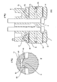
Fig. 1 ist eine Kipphebelanordnung 1 mit zwei Kipphebeln 2, 3 dargestellt, die mit Bohrungen 4, 5 jeweils seitlich auf eine Achse 6 schwenkbeweglich aufgesteckt sind. Die Achse 6 ist mit Schrauben 7 auf einem Lagerbock 8 befestigt, der sich seitlich jeweils bis unter die Bereiche der Kipphebel 2, 3 erstreckt. - Für eine axiale Lagesicherung der Kipphebel 2, 3 ist an diesen jeweils ein abragendes, auf den Lagerbock hingerichtetes Eingriffselement geformt. Diese Eingriffselemente sind als Ringstegteile 9, 10 ausgebildet und sind Federelemente einer Nut-Feder-Verbindung. Die Nutelemente als Gegenelemente sind als Ringnutteile 11, 12 am einstückigen Lagerbock 8 z.B. durch Fräsen eingebracht.
- Insbesondere aus der Seitenansicht nach
Fig. 2 ist ersichtlich, dass die Ringstegteile 9, 10 jeweils seitlich den Bereich des Lagerbocks 8 so weit überragen, dass über den gesamten Kipphebelschwenkweg (Pfeil 13) ein voller Eingriff in das jeweils zugeordnete Ringnutteil 11, 12 mit einer axialen Flankenabstützung zwischen den Ringstegteilen 9, 10 und den zugeordneten Ringnutteilen 11, 12 gewährleistet ist. - Im Schnitt nach
Fig. 3 ist wiederum der Lagerbock 8 mit den beiden Ringnutteilen 11, 12 und die mit der Schraubverbindung 7 gehaltene Achse 6 ersichtlich. Zudem sind Ölführungskanäle 14 mit Austrittsbohrungen 15 dargestellt. Die jeweils seitlich auf die Achse 6 aufgesteckten Kipphebel 2, 3 greifen mit ihren Ringstegteilen 9, 10 formschlüssig mit einem geringen Flankenspiel in die Ringnutteile 11, 12 für die axiale Lagesicherung ein. - In
Fig. 4 ist der Eingriffsbereich zwischen dem Ringnutteil 11 und dem Ringstegteil 9 vergrößert dargestellt, wobei hier deutlich die beidseitige axiale Flankenabstützung 16, 17 erkennbar ist. Weiter sind in derFig. 4 ringnutteilseitig ausgebildeten Gleitschrägen 18, 19 erkennbar, die zur Montageerleichterung dienen. - Zur Montage der Kipphebelanordnung 1 werden in einem ersten Montageschritt die Kipphebel 2, 3 auf die Achse 6 gesteckt. In einem zweiten Montageschritt wird dann die vormontierte Kipphebel-Achse-Baugruppe auf den Lagerbock 8 unter Herstellung der Eingriffsverbindung zwischen den Ringstegteilen 9, 10 und den Ringnutteilen 11, 12 gesetzt und dort mittels der Schraubverbindung 7 befestigt.
Claims (11)
- Lagerung eines Kipphebels für einen Ventiltrieb einer Brennkraftmaschine, mit einem Kipphebellagerbock (8), an dem eine Achse (6) angeordnet ist, auf die der Kipphebel (2, 3) mit einer zugeordneten Bohrung (4, 5) schwenkbar aufgesteckt und mittels einer axialen Lagesicherung gehalten ist, dadurch gekennzeichnet, dass die axiale Lagesicherung eine Führungsverbindung als Eingriffselement-Gegenelement-Verbindung zwischen dem Lagerbock (8) und dem Kipphebel (2, 3) ist, bei der ein quer zur Achsrichtung ausgerichtetes Eingriffselement (9, 10) in ein zugeordnetes Gegenelement (11, 12) mit axialer Flankenabstützung (16, 17) schwenkbeweglich eingreift.
- Lagerung nach Anspruch 1, dadurch gekennzeichnet, dass das Eingriffselement ein Federelement (9, 10) und das Gegenelement eine Nut (11, 12) einer Führungsverbindung als Nut-Feder-Verbindung ist.
- Lagerung nach Anspruch 2, dadurch gekennzeichnet, dass das Federelement als Teil eines im Bereich des Lagerbocks (8) am Kipphebelumfang angeordneten Ringstegs (9, 10) ausgebildet ist, der in eine zugeordnete Nut (11, 12) am Lagerbock (8) eingreift.
- Lagerung nach Anspruch 3, dadurch gekennzeichnet, dass das Federelement (9, 10) am Kipphebel (2, 3) einstückig geformt, vorzugsweise bei einem Kipphebel (2, 3) als Schmiedeteil präzisionsgeschmiedet ist und die Nut (11, 12) an einem einstückigen Lagerbock (8) gefräst ist.
- Lagerung nach Anspruch 3, dadurch gekennzeichnet,
dass das Federelement als separates Bauteil hergestellt und am Kipphebel (2, 3) angebracht ist und/oder
dass der Lagerbock (8) mehrteilig, insbesondere mit einer Trennebene im Nutbereich ausgeführt ist. - Lagerung nach einem der Ansprüche 3 bis 5, dadurch gekennzeichnet, dass die Nut (11, 12) am Lagerbock (8) wannenartig ausgebildet ist.
- Lagerung nach einem der Ansprüche 1 bis 6, dadurch gekennzeichnet, dass eine gezielte Ölzuführung (14, 15) an den Bereich eines Eingriffselement-Gegenelement-Kontakts vorgesehen ist, insbesondere durch wenigstens eine Bohrung im Kipphebel und/oder im Lagerbock und/oder durch wenigstens eine Spritzdüse.
- Lagerung nach einem der Ansprüche 1 bis 7, dadurch gekennzeichnet, dass das Eingriffselement (9, 10) und/oder das Gegenelement (11, 12) mit Gleitschrägen (18, 19) zur Montageerleichterung ausgeführt sind.
- Lagerung nach einem der Ansprüche 1 bis 8, dadurch gekennzeichnet, dass die Eingriffselement-Gegenelement-Verbindung insbesondere bezüglich der Flankenabstützung (16, 17) ein gegebenenfalls über den Bewegungsweg variierendes Spiel von 0,1mm bis 1,0mm, vorzugsweise von 0,10mm bis 0,45mm, besonders bevorzugt von 0,25mm bis 0,35mm, aufweist.
- Lagerung nach einem der Ansprüche 1 bis 9, dadurch gekennzeichnet, dass zwischen dem Eingriffselement (9, 10) und dem Gegenelement (11, 12) über den Bewegungsweg nur in Teilbereichen eine formschlüssige Verbindung besteht.
- Verfahren zur Montage einer Lagerung nach den Ansprüchen 1 bis 10, dadurch gekennzeichnet dass in einem ersten Montageschritt der Kipphebel (2, 3) auf die Achse (6) gesteckt und in einem zweiten Montageschritt die Kipphebel-Achse-Baugruppe auf den Lagerbock (8) unter Herstellung der Eingriffselement-Gegenelement-Verbindung gesetzt und befestigt wird.
Applications Claiming Priority (1)
| Application Number | Priority Date | Filing Date | Title |
|---|---|---|---|
| DE102012013220.4A DE102012013220A1 (de) | 2012-07-04 | 2012-07-04 | Lagerung eines Kipphebels für einen Ventiltrieb einer Brennkraftmaschine |
Publications (2)
| Publication Number | Publication Date |
|---|---|
| EP2682570A1 true EP2682570A1 (de) | 2014-01-08 |
| EP2682570B1 EP2682570B1 (de) | 2014-09-24 |
Family
ID=48746194
Family Applications (1)
| Application Number | Title | Priority Date | Filing Date |
|---|---|---|---|
| EP13003163.6A Active EP2682570B1 (de) | 2012-07-04 | 2013-06-21 | Lagerung eines Kipphebels für einen Ventiltrieb einer Brennkraftmaschine |
Country Status (5)
| Country | Link |
|---|---|
| EP (1) | EP2682570B1 (de) |
| CN (1) | CN103527277B (de) |
| BR (1) | BR102013017199B1 (de) |
| DE (1) | DE102012013220A1 (de) |
| RU (1) | RU2628469C2 (de) |
Families Citing this family (1)
| Publication number | Priority date | Publication date | Assignee | Title |
|---|---|---|---|---|
| DE102015210691A1 (de) * | 2015-06-11 | 2016-12-15 | Schaeffler Technologies AG & Co. KG | Kipphebel für einen Ventiltrieb einer Brennkraftmaschine |
Citations (7)
| Publication number | Priority date | Publication date | Assignee | Title |
|---|---|---|---|---|
| US1346116A (en) * | 1919-06-25 | 1920-07-13 | Gen Motors Corp | Lubricating means for valve-operating devices |
| US2908262A (en) * | 1958-08-27 | 1959-10-13 | Ford Motor Co | Valve gear |
| US3200804A (en) * | 1963-03-20 | 1965-08-17 | Inc H C F Porsche K G Fa Dr | Internal combustion engine |
| DE1911299B1 (de) * | 1969-03-06 | 1971-01-14 | Rheinstahl Hanomag Ag | Lagerung fuer Kipphebel von Brennkraftmaschinen |
| EP0213787A1 (de) * | 1985-08-08 | 1987-03-11 | Honda Giken Kogyo Kabushiki Kaisha | Vorrichtung zum Antrieb der vier Ventile einer Brennkraftmaschine mit einer obenliegenden Nockenwelle |
| WO1995027842A1 (de) | 1994-04-06 | 1995-10-19 | Ina Wälzlager Schaeffler Kg | Schlepphebel für einen ventiltrieb einer brennkraftmaschine |
| US5730093A (en) * | 1996-08-07 | 1998-03-24 | Sandco Automotive Limited | Roller rocker arm |
Family Cites Families (1)
| Publication number | Priority date | Publication date | Assignee | Title |
|---|---|---|---|---|
| RU2046964C1 (ru) * | 1992-04-17 | 1995-10-27 | Казанский инструментальный и ремонтно-подшипниковый завод | Механизм газораспределения двигателя внутреннего сгорания |
-
2012
- 2012-07-04 DE DE102012013220.4A patent/DE102012013220A1/de not_active Withdrawn
-
2013
- 2013-06-21 EP EP13003163.6A patent/EP2682570B1/de active Active
- 2013-07-03 BR BR102013017199-9A patent/BR102013017199B1/pt active IP Right Grant
- 2013-07-03 RU RU2013130662A patent/RU2628469C2/ru active
- 2013-07-04 CN CN201310278373.0A patent/CN103527277B/zh active Active
Patent Citations (7)
| Publication number | Priority date | Publication date | Assignee | Title |
|---|---|---|---|---|
| US1346116A (en) * | 1919-06-25 | 1920-07-13 | Gen Motors Corp | Lubricating means for valve-operating devices |
| US2908262A (en) * | 1958-08-27 | 1959-10-13 | Ford Motor Co | Valve gear |
| US3200804A (en) * | 1963-03-20 | 1965-08-17 | Inc H C F Porsche K G Fa Dr | Internal combustion engine |
| DE1911299B1 (de) * | 1969-03-06 | 1971-01-14 | Rheinstahl Hanomag Ag | Lagerung fuer Kipphebel von Brennkraftmaschinen |
| EP0213787A1 (de) * | 1985-08-08 | 1987-03-11 | Honda Giken Kogyo Kabushiki Kaisha | Vorrichtung zum Antrieb der vier Ventile einer Brennkraftmaschine mit einer obenliegenden Nockenwelle |
| WO1995027842A1 (de) | 1994-04-06 | 1995-10-19 | Ina Wälzlager Schaeffler Kg | Schlepphebel für einen ventiltrieb einer brennkraftmaschine |
| US5730093A (en) * | 1996-08-07 | 1998-03-24 | Sandco Automotive Limited | Roller rocker arm |
Also Published As
| Publication number | Publication date |
|---|---|
| CN103527277A (zh) | 2014-01-22 |
| RU2628469C2 (ru) | 2017-08-17 |
| RU2013130662A (ru) | 2015-01-10 |
| EP2682570B1 (de) | 2014-09-24 |
| CN103527277B (zh) | 2017-01-18 |
| DE102012013220A1 (de) | 2014-01-09 |
| BR102013017199B1 (pt) | 2020-11-03 |
| BR102013017199A2 (pt) | 2015-06-30 |
Similar Documents
| Publication | Publication Date | Title |
|---|---|---|
| EP3015727A1 (de) | Kurbelwellen- oder pleuellagerung einer verbrennungskraftmaschine oder eines kompressors | |
| WO2016116105A1 (de) | Lageranordnung und abgasturbolader | |
| WO2014076191A1 (de) | Lageranordnung | |
| WO2014079419A1 (de) | Elastisch abgestützte wälzlageranordnung | |
| WO2012104242A1 (de) | Vorrichtung zur veränderung der relativen winkellage einer nockenwelle gegenüber einer kurbelwelle einer brennkraftmaschine | |
| EP2744986B1 (de) | Verstellbare nockenwellenanordnung | |
| DE4204252C2 (de) | Kunststofflager für Stabilisatoren in Kraftfahrzeugen | |
| AT519652B1 (de) | Dichtungsvorrichtung und Hydraulikkolben mit Dichtungsvorrichtung | |
| DE102014213505B4 (de) | Elektrozylinder, dessen Spindellagerung eine Stützvorrichtung mit einem querbeweglichem Drehlager aufweist | |
| EP2682570B1 (de) | Lagerung eines Kipphebels für einen Ventiltrieb einer Brennkraftmaschine | |
| EP3014145B1 (de) | Verstellbare nockenwelle | |
| DE102010005603B4 (de) | Nockenwellenverstellanordnung mit einem als Wälzlager ausgebildetem Nockenwellenlager | |
| DE102013215556A1 (de) | Lageranordnung | |
| EP3510258B1 (de) | Variable nockenwellensteuerung | |
| DE102018208200B4 (de) | Aktuator mit einem Spindelantrieb sowie steer-by-wire-Lenkung | |
| DE102014218872A1 (de) | Anordnung eines Kipphebels für den Ventiltrieb einer Brennkraftmaschine | |
| DE102012107857B4 (de) | Lagerbuchse | |
| DE102013221251B4 (de) | Schiebenockensystem mit Bügelarretierung und Fixierung | |
| DE102017219309B4 (de) | Aktuator einer Lenkung mit einem Spindelantrieb sowie Verfahren zur Montage eines Spindelantriebs | |
| DE102018208199A1 (de) | Aktuator mit einem Spindelantrieb sowie steer-by-wire Lenkung | |
| DE102013004422B4 (de) | Befestigungsanordnung eines Lageraußenringes in einer Bohrung eines Lagerbocks | |
| DE102017124614B4 (de) | Lagervorrichtung für einen Lenker einer Radaufhängung eines Fahrzeugs | |
| WO2013037515A1 (de) | Axiallagerung bei doppelnockenwellen, nockenwellenverstellvorrichtung und verbrennungskraftmaschine | |
| EP2416024B1 (de) | Linearwälzlager | |
| DE102016210307A1 (de) | Federbeinstützlageranordnung für ein Kraftfahrzeug |
Legal Events
| Date | Code | Title | Description |
|---|---|---|---|
| PUAI | Public reference made under article 153(3) epc to a published international application that has entered the european phase |
Free format text: ORIGINAL CODE: 0009012 |
|
| AK | Designated contracting states |
Kind code of ref document: A1 Designated state(s): AL AT BE BG CH CY CZ DE DK EE ES FI FR GB GR HR HU IE IS IT LI LT LU LV MC MK MT NL NO PL PT RO RS SE SI SK SM TR |
|
| AX | Request for extension of the european patent |
Extension state: BA ME |
|
| 17P | Request for examination filed |
Effective date: 20140125 |
|
| GRAP | Despatch of communication of intention to grant a patent |
Free format text: ORIGINAL CODE: EPIDOSNIGR1 |
|
| INTG | Intention to grant announced |
Effective date: 20140520 |
|
| GRAS | Grant fee paid |
Free format text: ORIGINAL CODE: EPIDOSNIGR3 |
|
| GRAA | (expected) grant |
Free format text: ORIGINAL CODE: 0009210 |
|
| AK | Designated contracting states |
Kind code of ref document: B1 Designated state(s): AL AT BE BG CH CY CZ DE DK EE ES FI FR GB GR HR HU IE IS IT LI LT LU LV MC MK MT NL NO PL PT RO RS SE SI SK SM TR |
|
| REG | Reference to a national code |
Ref country code: GB Ref legal event code: FG4D Free format text: NOT ENGLISH |
|
| REG | Reference to a national code |
Ref country code: CH Ref legal event code: EP |
|
| REG | Reference to a national code |
Ref country code: AT Ref legal event code: REF Ref document number: 688750 Country of ref document: AT Kind code of ref document: T Effective date: 20141015 |
|
| REG | Reference to a national code |
Ref country code: IE Ref legal event code: FG4D Free format text: LANGUAGE OF EP DOCUMENT: GERMAN |
|
| REG | Reference to a national code |
Ref country code: DE Ref legal event code: R096 Ref document number: 502013000107 Country of ref document: DE Effective date: 20141106 |
|
| REG | Reference to a national code |
Ref country code: SE Ref legal event code: TRGR |
|
| REG | Reference to a national code |
Ref country code: NL Ref legal event code: T3 |
|
| PG25 | Lapsed in a contracting state [announced via postgrant information from national office to epo] |
Ref country code: NO Free format text: LAPSE BECAUSE OF FAILURE TO SUBMIT A TRANSLATION OF THE DESCRIPTION OR TO PAY THE FEE WITHIN THE PRESCRIBED TIME-LIMIT Effective date: 20141224 Ref country code: FI Free format text: LAPSE BECAUSE OF FAILURE TO SUBMIT A TRANSLATION OF THE DESCRIPTION OR TO PAY THE FEE WITHIN THE PRESCRIBED TIME-LIMIT Effective date: 20140924 Ref country code: GR Free format text: LAPSE BECAUSE OF FAILURE TO SUBMIT A TRANSLATION OF THE DESCRIPTION OR TO PAY THE FEE WITHIN THE PRESCRIBED TIME-LIMIT Effective date: 20141225 Ref country code: LT Free format text: LAPSE BECAUSE OF FAILURE TO SUBMIT A TRANSLATION OF THE DESCRIPTION OR TO PAY THE FEE WITHIN THE PRESCRIBED TIME-LIMIT Effective date: 20140924 |
|
| REG | Reference to a national code |
Ref country code: LT Ref legal event code: MG4D |
|
| PG25 | Lapsed in a contracting state [announced via postgrant information from national office to epo] |
Ref country code: CY Free format text: LAPSE BECAUSE OF FAILURE TO SUBMIT A TRANSLATION OF THE DESCRIPTION OR TO PAY THE FEE WITHIN THE PRESCRIBED TIME-LIMIT Effective date: 20140924 Ref country code: LV Free format text: LAPSE BECAUSE OF FAILURE TO SUBMIT A TRANSLATION OF THE DESCRIPTION OR TO PAY THE FEE WITHIN THE PRESCRIBED TIME-LIMIT Effective date: 20140924 Ref country code: RS Free format text: LAPSE BECAUSE OF FAILURE TO SUBMIT A TRANSLATION OF THE DESCRIPTION OR TO PAY THE FEE WITHIN THE PRESCRIBED TIME-LIMIT Effective date: 20140924 Ref country code: HR Free format text: LAPSE BECAUSE OF FAILURE TO SUBMIT A TRANSLATION OF THE DESCRIPTION OR TO PAY THE FEE WITHIN THE PRESCRIBED TIME-LIMIT Effective date: 20140924 |
|
| PG25 | Lapsed in a contracting state [announced via postgrant information from national office to epo] |
Ref country code: PT Free format text: LAPSE BECAUSE OF FAILURE TO SUBMIT A TRANSLATION OF THE DESCRIPTION OR TO PAY THE FEE WITHIN THE PRESCRIBED TIME-LIMIT Effective date: 20150126 Ref country code: SK Free format text: LAPSE BECAUSE OF FAILURE TO SUBMIT A TRANSLATION OF THE DESCRIPTION OR TO PAY THE FEE WITHIN THE PRESCRIBED TIME-LIMIT Effective date: 20140924 Ref country code: CZ Free format text: LAPSE BECAUSE OF FAILURE TO SUBMIT A TRANSLATION OF THE DESCRIPTION OR TO PAY THE FEE WITHIN THE PRESCRIBED TIME-LIMIT Effective date: 20140924 Ref country code: RO Free format text: LAPSE BECAUSE OF FAILURE TO SUBMIT A TRANSLATION OF THE DESCRIPTION OR TO PAY THE FEE WITHIN THE PRESCRIBED TIME-LIMIT Effective date: 20140924 Ref country code: IS Free format text: LAPSE BECAUSE OF FAILURE TO SUBMIT A TRANSLATION OF THE DESCRIPTION OR TO PAY THE FEE WITHIN THE PRESCRIBED TIME-LIMIT Effective date: 20150124 Ref country code: ES Free format text: LAPSE BECAUSE OF FAILURE TO SUBMIT A TRANSLATION OF THE DESCRIPTION OR TO PAY THE FEE WITHIN THE PRESCRIBED TIME-LIMIT Effective date: 20140924 Ref country code: EE Free format text: LAPSE BECAUSE OF FAILURE TO SUBMIT A TRANSLATION OF THE DESCRIPTION OR TO PAY THE FEE WITHIN THE PRESCRIBED TIME-LIMIT Effective date: 20140924 |
|
| PG25 | Lapsed in a contracting state [announced via postgrant information from national office to epo] |
Ref country code: PL Free format text: LAPSE BECAUSE OF FAILURE TO SUBMIT A TRANSLATION OF THE DESCRIPTION OR TO PAY THE FEE WITHIN THE PRESCRIBED TIME-LIMIT Effective date: 20140924 |
|
| REG | Reference to a national code |
Ref country code: DE Ref legal event code: R097 Ref document number: 502013000107 Country of ref document: DE |
|
| PG25 | Lapsed in a contracting state [announced via postgrant information from national office to epo] |
Ref country code: DK Free format text: LAPSE BECAUSE OF FAILURE TO SUBMIT A TRANSLATION OF THE DESCRIPTION OR TO PAY THE FEE WITHIN THE PRESCRIBED TIME-LIMIT Effective date: 20140924 |
|
| PLBE | No opposition filed within time limit |
Free format text: ORIGINAL CODE: 0009261 |
|
| STAA | Information on the status of an ep patent application or granted ep patent |
Free format text: STATUS: NO OPPOSITION FILED WITHIN TIME LIMIT |
|
| 26N | No opposition filed |
Effective date: 20150625 |
|
| PG25 | Lapsed in a contracting state [announced via postgrant information from national office to epo] |
Ref country code: MC Free format text: LAPSE BECAUSE OF FAILURE TO SUBMIT A TRANSLATION OF THE DESCRIPTION OR TO PAY THE FEE WITHIN THE PRESCRIBED TIME-LIMIT Effective date: 20140924 |
|
| PG25 | Lapsed in a contracting state [announced via postgrant information from national office to epo] |
Ref country code: LU Free format text: LAPSE BECAUSE OF FAILURE TO SUBMIT A TRANSLATION OF THE DESCRIPTION OR TO PAY THE FEE WITHIN THE PRESCRIBED TIME-LIMIT Effective date: 20150621 Ref country code: SI Free format text: LAPSE BECAUSE OF FAILURE TO SUBMIT A TRANSLATION OF THE DESCRIPTION OR TO PAY THE FEE WITHIN THE PRESCRIBED TIME-LIMIT Effective date: 20140924 |
|
| REG | Reference to a national code |
Ref country code: IE Ref legal event code: MM4A |
|
| PG25 | Lapsed in a contracting state [announced via postgrant information from national office to epo] |
Ref country code: IE Free format text: LAPSE BECAUSE OF NON-PAYMENT OF DUE FEES Effective date: 20150621 |
|
| REG | Reference to a national code |
Ref country code: FR Ref legal event code: PLFP Year of fee payment: 4 |
|
| PG25 | Lapsed in a contracting state [announced via postgrant information from national office to epo] |
Ref country code: MT Free format text: LAPSE BECAUSE OF FAILURE TO SUBMIT A TRANSLATION OF THE DESCRIPTION OR TO PAY THE FEE WITHIN THE PRESCRIBED TIME-LIMIT Effective date: 20140924 |
|
| REG | Reference to a national code |
Ref country code: CH Ref legal event code: PL |
|
| PG25 | Lapsed in a contracting state [announced via postgrant information from national office to epo] |
Ref country code: CH Free format text: LAPSE BECAUSE OF NON-PAYMENT OF DUE FEES Effective date: 20160630 Ref country code: LI Free format text: LAPSE BECAUSE OF NON-PAYMENT OF DUE FEES Effective date: 20160630 |
|
| PG25 | Lapsed in a contracting state [announced via postgrant information from national office to epo] |
Ref country code: HU Free format text: LAPSE BECAUSE OF FAILURE TO SUBMIT A TRANSLATION OF THE DESCRIPTION OR TO PAY THE FEE WITHIN THE PRESCRIBED TIME-LIMIT; INVALID AB INITIO Effective date: 20130621 Ref country code: BG Free format text: LAPSE BECAUSE OF FAILURE TO SUBMIT A TRANSLATION OF THE DESCRIPTION OR TO PAY THE FEE WITHIN THE PRESCRIBED TIME-LIMIT Effective date: 20140924 |
|
| REG | Reference to a national code |
Ref country code: FR Ref legal event code: PLFP Year of fee payment: 5 |
|
| PG25 | Lapsed in a contracting state [announced via postgrant information from national office to epo] |
Ref country code: BE Free format text: LAPSE BECAUSE OF NON-PAYMENT OF DUE FEES Effective date: 20150630 |
|
| PG25 | Lapsed in a contracting state [announced via postgrant information from national office to epo] |
Ref country code: TR Free format text: LAPSE BECAUSE OF FAILURE TO SUBMIT A TRANSLATION OF THE DESCRIPTION OR TO PAY THE FEE WITHIN THE PRESCRIBED TIME-LIMIT Effective date: 20140924 |
|
| GBPC | Gb: european patent ceased through non-payment of renewal fee |
Effective date: 20170621 |
|
| PG25 | Lapsed in a contracting state [announced via postgrant information from national office to epo] |
Ref country code: GB Free format text: LAPSE BECAUSE OF NON-PAYMENT OF DUE FEES Effective date: 20170621 |
|
| PG25 | Lapsed in a contracting state [announced via postgrant information from national office to epo] |
Ref country code: SM Free format text: LAPSE BECAUSE OF FAILURE TO SUBMIT A TRANSLATION OF THE DESCRIPTION OR TO PAY THE FEE WITHIN THE PRESCRIBED TIME-LIMIT Effective date: 20140924 |
|
| PG25 | Lapsed in a contracting state [announced via postgrant information from national office to epo] |
Ref country code: MK Free format text: LAPSE BECAUSE OF FAILURE TO SUBMIT A TRANSLATION OF THE DESCRIPTION OR TO PAY THE FEE WITHIN THE PRESCRIBED TIME-LIMIT Effective date: 20140924 |
|
| REG | Reference to a national code |
Ref country code: FR Ref legal event code: PLFP Year of fee payment: 6 |
|
| PG25 | Lapsed in a contracting state [announced via postgrant information from national office to epo] |
Ref country code: AL Free format text: LAPSE BECAUSE OF FAILURE TO SUBMIT A TRANSLATION OF THE DESCRIPTION OR TO PAY THE FEE WITHIN THE PRESCRIBED TIME-LIMIT Effective date: 20140924 |
|
| REG | Reference to a national code |
Ref country code: AT Ref legal event code: MM01 Ref document number: 688750 Country of ref document: AT Kind code of ref document: T Effective date: 20180621 |
|
| REG | Reference to a national code |
Ref country code: DE Ref legal event code: R081 Ref document number: 502013000107 Country of ref document: DE Owner name: MAN TRUCK & BUS SE, DE Free format text: FORMER OWNER: MAN TRUCK & BUS AG, 80995 MUENCHEN, DE |
|
| PG25 | Lapsed in a contracting state [announced via postgrant information from national office to epo] |
Ref country code: AT Free format text: LAPSE BECAUSE OF NON-PAYMENT OF DUE FEES Effective date: 20180621 |
|
| PGFP | Annual fee paid to national office [announced via postgrant information from national office to epo] |
Ref country code: DE Payment date: 20250626 Year of fee payment: 13 |
|
| PGFP | Annual fee paid to national office [announced via postgrant information from national office to epo] |
Ref country code: NL Payment date: 20250624 Year of fee payment: 13 |
|
| PGFP | Annual fee paid to national office [announced via postgrant information from national office to epo] |
Ref country code: FR Payment date: 20250624 Year of fee payment: 13 |
|
| PGFP | Annual fee paid to national office [announced via postgrant information from national office to epo] |
Ref country code: SE Payment date: 20250619 Year of fee payment: 13 |
|
| PGFP | Annual fee paid to national office [announced via postgrant information from national office to epo] |
Ref country code: IT Payment date: 20250623 Year of fee payment: 13 |