EP2682568A1 - Heating System for a Thermal Electric Power Station Water Circuit - Google Patents
Heating System for a Thermal Electric Power Station Water Circuit Download PDFInfo
- Publication number
- EP2682568A1 EP2682568A1 EP13150864.0A EP13150864A EP2682568A1 EP 2682568 A1 EP2682568 A1 EP 2682568A1 EP 13150864 A EP13150864 A EP 13150864A EP 2682568 A1 EP2682568 A1 EP 2682568A1
- Authority
- EP
- European Patent Office
- Prior art keywords
- water
- heaters
- flow
- extracted
- heater
- Prior art date
- Legal status (The legal status is an assumption and is not a legal conclusion. Google has not performed a legal analysis and makes no representation as to the accuracy of the status listed.)
- Granted
Links
Images


Classifications
-
- F—MECHANICAL ENGINEERING; LIGHTING; HEATING; WEAPONS; BLASTING
- F24—HEATING; RANGES; VENTILATING
- F24H—FLUID HEATERS, e.g. WATER OR AIR HEATERS, HAVING HEAT-GENERATING MEANS, e.g. HEAT PUMPS, IN GENERAL
- F24H1/00—Water heaters, e.g. boilers, continuous-flow heaters or water-storage heaters
- F24H1/0018—Water heaters, e.g. boilers, continuous-flow heaters or water-storage heaters using electric energy supply
-
- F—MECHANICAL ENGINEERING; LIGHTING; HEATING; WEAPONS; BLASTING
- F01—MACHINES OR ENGINES IN GENERAL; ENGINE PLANTS IN GENERAL; STEAM ENGINES
- F01K—STEAM ENGINE PLANTS; STEAM ACCUMULATORS; ENGINE PLANTS NOT OTHERWISE PROVIDED FOR; ENGINES USING SPECIAL WORKING FLUIDS OR CYCLES
- F01K7/00—Steam engine plants characterised by the use of specific types of engine; Plants or engines characterised by their use of special steam systems, cycles or processes; Control means specially adapted for such systems, cycles or processes; Use of withdrawn or exhaust steam for feed-water heating
- F01K7/34—Steam engine plants characterised by the use of specific types of engine; Plants or engines characterised by their use of special steam systems, cycles or processes; Control means specially adapted for such systems, cycles or processes; Use of withdrawn or exhaust steam for feed-water heating the engines being of extraction or non-condensing type; Use of steam for feed-water heating
- F01K7/40—Use of two or more feed-water heaters in series
-
- F—MECHANICAL ENGINEERING; LIGHTING; HEATING; WEAPONS; BLASTING
- F01—MACHINES OR ENGINES IN GENERAL; ENGINE PLANTS IN GENERAL; STEAM ENGINES
- F01K—STEAM ENGINE PLANTS; STEAM ACCUMULATORS; ENGINE PLANTS NOT OTHERWISE PROVIDED FOR; ENGINES USING SPECIAL WORKING FLUIDS OR CYCLES
- F01K7/00—Steam engine plants characterised by the use of specific types of engine; Plants or engines characterised by their use of special steam systems, cycles or processes; Control means specially adapted for such systems, cycles or processes; Use of withdrawn or exhaust steam for feed-water heating
- F01K7/16—Steam engine plants characterised by the use of specific types of engine; Plants or engines characterised by their use of special steam systems, cycles or processes; Control means specially adapted for such systems, cycles or processes; Use of withdrawn or exhaust steam for feed-water heating the engines being only of turbine type
-
- F—MECHANICAL ENGINEERING; LIGHTING; HEATING; WEAPONS; BLASTING
- F22—STEAM GENERATION
- F22B—METHODS OF STEAM GENERATION; STEAM BOILERS
- F22B1/00—Methods of steam generation characterised by form of heating method
- F22B1/02—Methods of steam generation characterised by form of heating method by exploitation of the heat content of hot heat carriers
- F22B1/023—Methods of steam generation characterised by form of heating method by exploitation of the heat content of hot heat carriers with heating tubes for nuclear reactors, as long as they are not classified according to a specified heating fluid, in another group
-
- F—MECHANICAL ENGINEERING; LIGHTING; HEATING; WEAPONS; BLASTING
- F22—STEAM GENERATION
- F22D—PREHEATING, OR ACCUMULATING PREHEATED, FEED-WATER FOR STEAM GENERATION; FEED-WATER SUPPLY FOR STEAM GENERATION; CONTROLLING WATER LEVEL FOR STEAM GENERATION; AUXILIARY DEVICES FOR PROMOTING WATER CIRCULATION WITHIN STEAM BOILERS
- F22D1/00—Feed-water heaters, i.e. economisers or like preheaters
- F22D1/32—Feed-water heaters, i.e. economisers or like preheaters arranged to be heated by steam, e.g. bled from turbines
- F22D1/325—Schematic arrangements or control devices therefor
Definitions
- the present invention relates to the field of heating systems for the water circuit of the water-steam cycle of thermal electric power stations.
- the heating system of the invention applies notably to nuclear power stations and, in particular, to power stations provided with a boiling water reactor (BWR), but can also be applied to other types of thermal electric power station.
- BWR boiling water reactor
- the invention more particularly relates to the circuits for recovering heat between, on the one hand, the outlet of at least one condenser and, on the other hand, the inlet of a steam generator system of a power station.
- the key problem is that it is necessary to convey a flow of water to the inlet of a steam generator system at a given temperature while at the same time making maximum reuse of the energy of the water in steam or condensed form at all stages of the treatments.
- the issue is therefore one of minimizing the losses of heat energy and of optimizing reuse in the overall operation of a power station.
- a power station has a number of constraints on the structural integration of the various elements of which it is made up and this means that certain compromises have to be made.
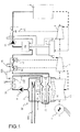
- Figure 1 depicts a conventional design of a thermal electric power station comprising a steam generator system 1, a set of high-pressure turbines 8, a set of medium-pressure turbines 9, and a set of low-pressure turbines 10. There is conventionally also an alternator 11 and a condenser 6. A system provides a flow of cooling water to the condenser 6.
- the steam generator system 1 and the high-pressure, medium-pressure and low-pressure turbines, the alternator 11, the external circulation circuit 300 and the condenser 6 make up the key elements of the primary circuit of a power station.
- the medium-pressure and low-pressure turbines may be combined.
- a circuit for extracting water condensed from water extracted from the condenser 6 by a pump 4 comprises a purification system 35, denoted SP, otherwise known as a "polishing system", followed by a heating circuit made up of several sets of heaters.
- SP purification system 35
- a heating circuit made up of several sets of heaters.
- the principle relies on recovering some of the residual heat from the steam tapped off at chosen points in the turbine for the purposes of heating up the water fed to the steam generator system.
- the steam inlets 20, 21 and 23 allow the water of the circuit 30 to be heated up gradually to ensure a flow of water reinjected into the inlet side of the steam generator system 1 at the desired temperature.
- the heaters LP1, LP2, LP3, LP4, the feed tank, denoted BA, and the group of heaters denoted HP are mounted in series with respect to the flow of water extracted from the condenser 6 so as to optimize the thermodynamic water-heating cycle.
- a cooler 7, denoted RC is positioned upstream of the heating circuit to cool condensate from the heater LP3 before it is returned to the condenser 6.
- a first set of heaters is generally incorporated into a structure comprising the condenser 6 and the low-pressure turbine 10.
- this first set comprises the heaters LP1 and LP2.
- a second set of heaters comprising the heaters LP3 and LP4, is arranged generally outside of the structure comprising the condenser 6.
- the conventional solution is to cool this condensate before returning it to the condenser 6, in order to avoid significant losses of heat energy.
- the condensate 100 coming from the second set is injected into the cooler 7 in order to return colder water to the condenser 6 via the outlet 13 of the cooler 7.
- a second known alternative is systematically to cascade the condensate from one heater into the heater of lower rank.
- this solution cannot prudently be applied to heaters incorporated into a structure comprising the condenser 6 and the low-pressure turbine 10 because these tappings are not fitted with nonreturn valves and the backflow of a mixture of cold revaporized water and condensate to the turbine, notably in the event of a sudden sharp pressure drop, could lead to turbine blade damage.
- the configuration of fitting a drain cooler 7 upstream of the first set of heaters LP is generally the one adopted for reasons of reliability, ease of maintenance and water quality, to the relative detriment of energy efficiency.
- the invention makes it possible to alleviate the abovementioned disadvantages.
- One objective of the invention is to make available a system for heating the circuit of water to be conveyed to the steam generator system that allows an optimized energy balance while at the same time guaranteeing maximum level of safety for the turbine, minimum maintenance effort and the possibility of best chemical quality of the feedwater.
- the invention relates to a heating system for a thermal electric power station water circuit, comprising:
- This "in-parallel" configuration of the equipment makes it possible to reduce the flow of extracted water passing through the first set of heaters and thus minimize the flow of steam needed to heat up the extracted water in the first set of heaters.
- such a configuration allows the flow of extracted water coming from the extraction system to be split into a first fraction feeding, via its water inlet referred to as the extracted-water-for-heating inlet, the first set of heaters and a complementary fraction feeding, via its second water inlet, the condensate cooler of the second set of heaters.
- Such a feature notably makes it possible to reduce the flow of tapped-off steam needed for heating the extracted water in the first set of heaters, the reduction being justified by the fact that the first fraction represents less than 100% of the flow of extracted water coming from the extraction system.
- such a feature allows the condensate cooler to be fed with a complementary fraction less than 100% of the flow of extracted water coming from the extraction system, this complementary fraction making it possible, at its second, heated water, outlet, to supply water at a temperature higher than is achieved by the existing devices.
- the heating system comprises means for regulating the flow of water coming from the extraction system to allow adjustment of the complementary fraction of the flow of water fed to the cooler.
- this complementary fraction allows the flow of water fed to the cooler to be adjusted optimally in order to obtain optimized ultimate efficiency of the thermal electric power station.
- the complementary fraction of the flow of water fed to the cooler represents, in percentage terms, between 2 and 20%, and preferably between 5 and 15%, of the flow of water coming from the extraction system.
- the first set of heaters comprises at least one first heater and one second heater which are arranged in cascade so that a fraction of the water heated up by the steam introduced into the second heater is reinjected either into the first heater or into the condenser.
- the second set of heaters comprises at least one third heater and one fourth heater arranged in cascade such that a fraction of the condensate from the steam introduced into the fourth heater is reinjected into the third heater.
- a polishing setup is arranged between the extraction system extracting water from the condenser and the inlet of the first set of heaters so as to filter out particles present and trap salts dissolved in the water that is to be heated in the water circuit.
- the invention also relates to a thermal electric power station which comprises a system for heating a water circuit, said water circuit heating system comprising:
- heaters mounted in series that means that the water outlet from one heater is fed, at least in part, to the inlet of another heater.
- a first heater may be said to be situated upstream of a second heater when it treats the water coming from the extraction system before the second heater.
- condensate cooler In the remainder of the description, a condensate cooler will be termed a "cooler". A flow of water condensed from the steam of the cycle will also be referred to as condensate.
- Figure 2 depicts a heating system of a thermal electric power station water circuit comprising a first set 101 of heaters, denoted A, which can be used to heat a flow of water 104 to an inlet temperature T1.
- the flow of water 104 at the inlet of the first set 101 of heaters comes from an extraction system 4 extracting water at the outlet from a condenser C delivering a flow of water 103 at a temperature T1 substantially equal to the inlet temperature.
- the first set 101 of heaters comprises a plurality of heaters in a cascade architecture.
- the first set of heaters comprises two heaters LP1, LP2 in cascade.
- a heater is a device that allows the water to be heated by heat transfer. This exchange of heat takes place between, on the one hand, a flow of steam 111 entering the first set of heaters which condenses in the device and reemerges from the device via an outlet 18, and, on the other hand, the flow of water 104 coming from the water extraction system 4 at the temperature T1 that this heat heats up to the temperature T2 of the circuit 109.
- the first set 101 of heaters delivers a flow of heated water 109 at a temperature T2 to the inlet of a second set 102 of heaters, denoted B.
- the second set 102 of heaters heats a flow of water at inlet 109' to an inlet temperature T2' thanks to an exchange of heat with a flow of steam 112 entering the second set 102 which condenses and reemerges from the set B at outlet 108.
- the first set 101 of heaters and the second set 102 of heaters are arranged in series with respect to the flow of water coming from the water extraction system.
- the heating system of the invention comprises a cooler 7, denoted RC, external to the two sets of coolers and arranged in parallel with the first set of heaters with respect to the flow of water coming from the extraction system 4.
- This is a condensate cooler used to cool the condensate 108 from the second set 102 of heaters.
- the flow of water coming from the extraction system 4 is split into a first fraction 104 conveyed to the first set 101 of heaters and a complementary fraction 105 conveyed to the cooler 7.
- the apportioning of the flow of water is determined by balancing the pressure drops across the two circuits.
- the cooler 7 comprises a second water inlet 108 coming from condensate from the second set 102 of heaters.
- the cooler comprises a heat exchanger used to heat the complementary fraction 105 from the temperature T1 to a temperature T4 by cooling the flow 108 from the temperature T5 to the temperature T6.
- the flow 106 at the temperature T4 is mixed with the flow 109 at the temperature T2 to form the flow 109' at the temperature T'2 which constitutes the inlet of the second set 102 of heaters.
- the complementary fraction 105 can be adjusted so as advantageously to obtain a temperature T4 close to T2, this making it possible to limit irreversibility losses, it being understood here that the term "close to” means a difference of plus or minus 5 degrees Celsius.
- the condensate 108 from the second set 102 of heaters can be used to heat up the flow of water 105 coming from the water extraction system 4 without it passing through the first set 101 of heaters.
- This solution allows some of the heat energy of the condensate of a second set 102 of heaters to be recovered and also makes it possible to limit the amount of tapped-off steam 111 fed to the first set 101 of heaters.
- Figure 3 depicts a schematic diagram of the thermodynamic cycle in saturated steam in an electricity production station according to one particular embodiment in which a first set of exchangers 101 comprises two exchangers LP1 and LP2 and a second set of exchangers 102 comprises two exchangers LP3 and LP4.
- thermodynamic cycle illustrated here is that of a station comprising a nuclear power source (not illustrated) and turbines 8, 9, 10, the first being a high-pressure turbine 8, the second being a medium-pressure turbine 9, and the third being a low-pressure turbine 10.
- the driving fluid in this instance steam, flows successively through the high-pressure turbine 8, medium-pressure turbine 9 then low-pressure turbine 10.
- These turbines are able to turn a shaft of an alternator 11 able itself to produce electricity.
- a source of steam namely for example at least one steam generator 1, feeds the high-pressure module 8 with live steam.
- a drier(s)/superheater(s) assembly 2 is located between the high-pressure module 8 and the medium-pressure module 9, said drier(s)/superheater(s) assembly 2 being able to dry and superheat the steam derived from the high-pressure module 8, which steam is generated by the steam generator 1 upstream of said high-pressure module 8.
- This drier(s)/superheater(s) assembly 2 is also fed with live steam by a pipe taken from the outlet of the steam generator 1 to perform the superheating.
- a pipe feeds steam to a condenser 6 itself associated with a heat sink also known as an external circulation circuit 300.
- This condenser 6 has the effect of converting steam in gaseous form to liquid.
- a water extraction system 4 is positioned on the outlet side of a condenser 6, said water extraction system 4 feeding a water purification system 35.
- the flow of water coming from the extraction system 4 and from the water purification system 35 is then split into a first fraction 104 conveyed to a first set 101 of heaters and a second fraction 105 conveyed to a cooler 7.
- the first set 101 of heaters comprises two steam inlets 12 and 14 respectively feeding the first heater LP1 and the second heater LP2.
- the steam flows 12 and 14 correspond to the incoming steam flows of the first set of heaters 101, but the temperatures of these two inlets differ notably because configuring the heaters in series dictates that heating is performed at an increasing given temperatures gradient.
- the inlet 111 of figure 2 is therefore considered to be a schematic representation that does not take account of the differences in temperature and of state of the steam at the inlets to the heaters.
- the two heaters LP1 and LP2 are mounted in cascade in such a way that a fraction of the condensate 17 from the second exchanger LP2 is reinjected into the first exchanger LP1. Some of the heat of the water which is not used by the second heater LP2 is thus recovered.
- the residual water outlet 18, at a temperature T8, from the first heater is returned to the condenser 6.
- the second set 102 of heaters comprises, in this embodiment, a third heater LP3 and a fourth heater LP4.
- the two heaters of the second set of heaters are mounted in series with respect to the flow of treated water coming from the first set 101 of heaters and respectively allow a transfer of heat between the steam inlets 20 and 21 coming from tappings of the turbine to the extraction water passing through the heaters on its way to a feed tank BA also referred to as a degassing tank used to reduce the concentration of oxygen and other gases contained in the water.
- the third and fourth heaters LP3 and LP4 are mounted in cascade. What that means is that a fraction of the residual water 16 from the fourth exchanger LP4 is reinjected into the third exchanger LP3 to improve the thermodynamic cycle and the thermal efficiency of the heating circuit.
- the third LP3 and fourth LP4 heaters each comprise an inbuilt cooler 15 and 15' respectively.
- the third LP3 and fourth LP4 heaters are mounted in series with the fifth heater BA which is a mixing exchanger.
- a contact exchanger can be used without this having any impact on the general scope of the invention.
- the second set 102 of exchangers comprises a steam inlet 112 corresponding in flow to the two steam inlets 20 and 21 in the embodiment of figure 3 .
- the steam inlets of the second set allow steam to be delivered at different pressures and temperatures. This configuration makes it possible to guarantee an increasing temperature gradient in the second set of heaters and optimize the heating circuit and minimize energy losses.
- cooler 7 of the invention is that its installation is dissociated from the first set 101 of heaters which is incorporated into the turbine and condenser structure.
- the cooler 7 and the treatment of condensate can be configured in such a way as to benefit from the protective equipment associated with the heater LP3 thereby generating no risk to the turbine.
- the cooler 7 also is able to solve another problem specific to the circuit carrying water for heating in a thermal electric power station, notably that of maximizing the flow of water that can be treated by a filtration and polishing system in service.
- a device used for purifying the water of a power station also known as a "polishing system” that filters and removes minerals from the water flowing through the heating system.
- This configuration is used in particular for single tube steam generating systems and notably for boiling water reactors for which the water has as far as possible to be rid of solid particles and dissolved salts before it enters the steam generator system in order to limit damaging deposits therein.
- the temperatures at the various inlet and outlet points of the equipment are:
- these values come from implementing an embodiment in which the flow of water coming from the water extraction system 4 is split into a first fraction 104 conveyed to the first set 101 of heaters, this first fraction 104 representing substantially 90% of said flow of water coming from the extraction system 4, and a complementary fraction 105 conveyed to the cooler 7, this second fraction 105 then representing substantially 10% of said flow of water coming from the extraction system 4.
- the first fraction 104 represents a range of between 85 and 95% of the flow of water coming from the extraction system 4 and the second fraction 105 conveyed to the cooler 7 represents a range of values from between 15 and 5%. These values are in terms of percentages of the flow of water coming from the extraction system (4).
- the energy of the condensate from the heater LP3 is thus recovered at a temperature of 85°C, when this same energy would be recovered at a temperature of between 20°C and 30°C in the earlier configuration corresponding to the cooler in series.
Landscapes
- Engineering & Computer Science (AREA)
- Mechanical Engineering (AREA)
- General Engineering & Computer Science (AREA)
- Thermal Sciences (AREA)
- Combustion & Propulsion (AREA)
- Physics & Mathematics (AREA)
- Chemical & Material Sciences (AREA)
- Life Sciences & Earth Sciences (AREA)
- Sustainable Development (AREA)
- Sustainable Energy (AREA)
- Heat-Exchange Devices With Radiators And Conduit Assemblies (AREA)
- Heat Treatment Of Water, Waste Water Or Sewage (AREA)
- Extraction Or Liquid Replacement (AREA)
- Control Of Steam Boilers And Waste-Gas Boilers (AREA)
- Engine Equipment That Uses Special Cycles (AREA)
Abstract
Description
- The present invention relates to the field of heating systems for the water circuit of the water-steam cycle of thermal electric power stations. The heating system of the invention applies notably to nuclear power stations and, in particular, to power stations provided with a boiling water reactor (BWR), but can also be applied to other types of thermal electric power station. The invention more particularly relates to the circuits for recovering heat between, on the one hand, the outlet of at least one condenser and, on the other hand, the inlet of a steam generator system of a power station.
- In present-day thermal electric power stations optimizing the water heating circuit is of crucial importance, particularly as far as reducing energy costs are concerned.
- The key problem is that it is necessary to convey a flow of water to the inlet of a steam generator system at a given temperature while at the same time making maximum reuse of the energy of the water in steam or condensed form at all stages of the treatments. The issue is therefore one of minimizing the losses of heat energy and of optimizing reuse in the overall operation of a power station.
- It is necessary to consider various aspects when optimizing the energy efficiency of a thermal electric power station. In particular, a power station has a number of constraints on the structural integration of the various elements of which it is made up and this means that certain compromises have to be made.
- In this regard, the choice of configuration imposes certain safety constraints between the various elements of a thermal electric power station. The safety/efficiency compromise sometimes leads to a loss of heat energy and/or of efficiency in the energy circuit.
-
Figure 1 depicts a conventional design of a thermal electric power station comprising asteam generator system 1, a set of high-pressure turbines 8, a set of medium-pressure turbines 9, and a set of low-pressure turbines 10. There is conventionally also analternator 11 and a condenser 6. A system provides a flow of cooling water to the condenser 6. - The
steam generator system 1 and the high-pressure, medium-pressure and low-pressure turbines, thealternator 11, theexternal circulation circuit 300 and the condenser 6 make up the key elements of the primary circuit of a power station. In some instances, the medium-pressure and low-pressure turbines may be combined. - On the outlet side of the condenser 6, a circuit for extracting water condensed from water extracted from the condenser 6 by a
pump 4 comprises apurification system 35, denoted SP, otherwise known as a "polishing system", followed by a heating circuit made up of several sets of heaters. - The principle relies on recovering some of the residual heat from the steam tapped off at chosen points in the turbine for the purposes of heating up the water fed to the steam generator system. The
steam inlets circuit 30 to be heated up gradually to ensure a flow of water reinjected into the inlet side of thesteam generator system 1 at the desired temperature. - The heaters LP1, LP2, LP3, LP4, the feed tank, denoted BA, and the group of heaters denoted HP are mounted in series with respect to the flow of water extracted from the condenser 6 so as to optimize the thermodynamic water-heating cycle. In a conventional configuration, a
cooler 7, denoted RC, is positioned upstream of the heating circuit to cool condensate from the heater LP3 before it is returned to the condenser 6. - In a conventional way, for system architecture reasons, a first set of heaters is generally incorporated into a structure comprising the condenser 6 and the low-
pressure turbine 10. In the example illustrated, this first set comprises the heaters LP1 and LP2. - A second set of heaters, comprising the heaters LP3 and LP4, is arranged generally outside of the structure comprising the condenser 6.
- In general, prudent rules of design dictate that the
condensate 100 coming from this second set cannot be recovered directly in the first set of heaters incorporated into a structure comprising the condenser 6 and the low-pressure turbine 10. - Because the
condensate 100 coming from the second set of heaters cannot be conveyed directly to the first set, the conventional solution is to cool this condensate before returning it to the condenser 6, in order to avoid significant losses of heat energy. - In this type of configuration, the
condensate 100 coming from the second set is injected into thecooler 7 in order to return colder water to the condenser 6 via theoutlet 13 of thecooler 7. - There is, however, a significant loss in energy efficiency in the function of heating up the water in the
circuit 30 because of the large temperature difference notably between the outlet of thecooler 200 and thereturn 100. - There are solutions that make it possible to maximize the energy balance when heaters are mounted in cascade. For example, one known alternative is to fit a condensate recovery pump recovering condensate from one particular heater and reinject it into the feedwater circuit downstream of that same heater. Such a system does indeed allow recovery directly in the water cycle at a similar temperature level, therefore maximizing energy efficiency by minimizing temperature differences. However, this solution has several potential disadvantages.
- First of all, it adds additional equipment to the water system, particularly pumps, which have a cost, which require space in which to install them, and which demand a certain level of maintenance. Furthermore, the condensate pumped by a recovery pump does not pass through the purification system SP that purifies the water extracted from the condenser, thus reducing the chemical quality of the water in the circuit.
- A second known alternative is systematically to cascade the condensate from one heater into the heater of lower rank. As discussed earlier, this solution cannot prudently be applied to heaters incorporated into a structure comprising the condenser 6 and the low-
pressure turbine 10 because these tappings are not fitted with nonreturn valves and the backflow of a mixture of cold revaporized water and condensate to the turbine, notably in the event of a sudden sharp pressure drop, could lead to turbine blade damage. - Therefore, the configuration of fitting a
drain cooler 7 upstream of the first set of heaters LP is generally the one adopted for reasons of reliability, ease of maintenance and water quality, to the relative detriment of energy efficiency. - The invention makes it possible to alleviate the abovementioned disadvantages.
- One objective of the invention is to make available a system for heating the circuit of water to be conveyed to the steam generator system that allows an optimized energy balance while at the same time guaranteeing maximum level of safety for the turbine, minimum maintenance effort and the possibility of best chemical quality of the feedwater.
- The invention relates to a heating system for a thermal electric power station water circuit, comprising:
- an extraction system for extracting water from a condenser;
- a first set of heaters comprising:
- ○ at least one heater,
- ○ a water inlet, referred to as the extracted-water-for-heating inlet, fed with a first fraction of the flow of extracted water coming from the extraction system, and
- ○ at least one steam input intended to heat the extracted water, and;
- a second set of heaters comprising:
- ○ at least one heater arranged in series with respect to the extracted-water inlet of the first set of heaters, and
- ○ at least one steam input intended to heat the extracted water
- a first water inlet, referred to as the condensate inlet, fed by a condensate outlet of the second set of heaters;
- a second water inlet fed with a complementary fraction of the extracted-water flow coming from the extraction system;
- a first outlet for cooled condensate intended to be reinjected into the condenser, and;
- a second outlet for heated water so that a flow of water leaving the first set of heaters can be mixed with a flow of water derived from the second outlet of the drain cooler.
- This "in-parallel" configuration of the equipment makes it possible to reduce the flow of extracted water passing through the first set of heaters and thus minimize the flow of steam needed to heat up the extracted water in the first set of heaters.
- Specifically, by comparison with the prior art, such a configuration allows the flow of extracted water coming from the extraction system to be split into a first fraction feeding, via its water inlet referred to as the extracted-water-for-heating inlet, the first set of heaters and a complementary fraction feeding, via its second water inlet, the condensate cooler of the second set of heaters.
- The term "complementary" means that the sum of these fractions represents 100% of the flow of extracted water coming from the extraction system.
- Such a feature notably makes it possible to reduce the flow of tapped-off steam needed for heating the extracted water in the first set of heaters, the reduction being justified by the fact that the first fraction represents less than 100% of the flow of extracted water coming from the extraction system.
- On the other hand, such a feature allows the condensate cooler to be fed with a complementary fraction less than 100% of the flow of extracted water coming from the extraction system, this complementary fraction making it possible, at its second, heated water, outlet, to supply water at a temperature higher than is achieved by the existing devices.
- According to another advantageous feature, the heating system comprises means for regulating the flow of water coming from the extraction system to allow adjustment of the complementary fraction of the flow of water fed to the cooler.
- Specifically, this complementary fraction allows the flow of water fed to the cooler to be adjusted optimally in order to obtain optimized ultimate efficiency of the thermal electric power station.
- Advantageously, the complementary fraction of the flow of water fed to the cooler represents, in percentage terms, between 2 and 20%, and preferably between 5 and 15%, of the flow of water coming from the extraction system.
- Specifically, it has been noted with surprise that such values make it possible to obtain a heated water temperature at the second outlet of the condensate cooler which is at a temperature close to that of the water leaving the first set. Mixing these two flows at similar temperatures makes it possible to reduce irreversibility losses and to optimize the overall efficiency of the thermal electric power station. According to one particular technical aspect, the first set of heaters comprises at least one first heater and one second heater which are arranged in cascade so that a fraction of the water heated up by the steam introduced into the second heater is reinjected either into the first heater or into the condenser.
- According to another particular technical aspect, the second set of heaters comprises at least one third heater and one fourth heater arranged in cascade such that a fraction of the condensate from the steam introduced into the fourth heater is reinjected into the third heater.
- Advantageously, a polishing setup is arranged between the extraction system extracting water from the condenser and the inlet of the first set of heaters so as to filter out particles present and trap salts dissolved in the water that is to be heated in the water circuit.
- The invention also relates to a thermal electric power station which comprises a system for heating a water circuit, said water circuit heating system comprising:
- an extraction system for extracting water from a condenser;
- a first set of heaters comprising:
- ○ at least one heater,
- ○ a water inlet, referred to as the extracted-water-for-heating inlet, fed with a first fraction of the flow of extracted water coming from the extraction system, and
- ○ at least one steam input intended to heat the extracted water, and;
- a second set of heaters comprising:
- ○ at least one heater arranged in series with respect to the extracted-water inlet of the first set of heaters, and
- ○ at least one steam input intended to heat the extracted water;
- a first water inlet, referred to as the condensate inlet, fed by a condensate outlet of the second set of heaters;
- a second water inlet fed with a complementary fraction of the extracted-water flow coming from the extraction system;
- a first outlet for cooled condensate intended to be reinjected into the condenser, and;
- a second outlet for heated water so that a flow of water leaving the first set of heaters can be mixed with a flow of water derived from the second outlet of the drain cooler.
- Other features and advantages of the invention will be set out with the aid of the following description, given with reference to the attached drawings which depict:
-
figure 1 : a schematic diagram of a system of heaters of a water circuit of the prior art for a thermal electric power station; -
figure 2 : a schematic diagram of a system of heaters of a water circuit of the invention; -
figure 3 : a schematic diagram of one embodiment of the invention of a system of heaters of a water circuit. - For greater clarity, elements that are identical or similar will be identified by identical reference signs throughout the figures.
- In the remainder of the description, when a plurality of heaters is said to be "mounted in series" that means that the water outlet from one heater is fed, at least in part, to the inlet of another heater. In the description which follows, mention will be made of heaters mounted in series with respect to the flow of water coming from the
water extraction system 4. A first heater may be said to be situated upstream of a second heater when it treats the water coming from the extraction system before the second heater. - In the remainder of the description, when a plurality of heaters is said to be "mounted in cascade" that means that they are mounted in series and that some of the condensate from a second heater situated downstream of a first heater is reinjected into the first heater and mixed with the water outlet thereof.
- In the remainder of the description, a condensate cooler will be termed a "cooler". A flow of water condensed from the steam of the cycle will also be referred to as condensate.
-
Figure 2 depicts a heating system of a thermal electric power station water circuit comprising afirst set 101 of heaters, denoted A, which can be used to heat a flow ofwater 104 to an inlet temperature T1. The flow ofwater 104 at the inlet of thefirst set 101 of heaters comes from anextraction system 4 extracting water at the outlet from a condenser C delivering a flow ofwater 103 at a temperature T1 substantially equal to the inlet temperature. - The
first set 101 of heaters comprises a plurality of heaters in a cascade architecture. In the example offigure 3 , the first set of heaters comprises two heaters LP1, LP2 in cascade. - A heater is a device that allows the water to be heated by heat transfer. This exchange of heat takes place between, on the one hand, a flow of
steam 111 entering the first set of heaters which condenses in the device and reemerges from the device via anoutlet 18, and, on the other hand, the flow ofwater 104 coming from thewater extraction system 4 at the temperature T1 that this heat heats up to the temperature T2 of thecircuit 109. - The
first set 101 of heaters delivers a flow ofheated water 109 at a temperature T2 to the inlet of asecond set 102 of heaters, denoted B. Thesecond set 102 of heaters heats a flow of water at inlet 109' to an inlet temperature T2' thanks to an exchange of heat with a flow ofsteam 112 entering thesecond set 102 which condenses and reemerges from the set B atoutlet 108. - The
first set 101 of heaters and thesecond set 102 of heaters are arranged in series with respect to the flow of water coming from the water extraction system. - The heating system of the invention comprises a
cooler 7, denoted RC, external to the two sets of coolers and arranged in parallel with the first set of heaters with respect to the flow of water coming from theextraction system 4. This is a condensate cooler used to cool thecondensate 108 from thesecond set 102 of heaters. - The flow of water coming from the
extraction system 4 is split into afirst fraction 104 conveyed to thefirst set 101 of heaters and acomplementary fraction 105 conveyed to thecooler 7. - The term "complementary" means that the sum of these fractions represents 100% of the flow of extracted water coming from the extraction system.
- The apportioning of the flow of water is determined by balancing the pressure drops across the two circuits.
- The
cooler 7 comprises asecond water inlet 108 coming from condensate from thesecond set 102 of heaters. The cooler comprises a heat exchanger used to heat thecomplementary fraction 105 from the temperature T1 to a temperature T4 by cooling theflow 108 from the temperature T5 to the temperature T6. - The
flow 106 at the temperature T4 is mixed with theflow 109 at the temperature T2 to form the flow 109' at the temperature T'2 which constitutes the inlet of thesecond set 102 of heaters. Thecomplementary fraction 105 can be adjusted so as advantageously to obtain a temperature T4 close to T2, this making it possible to limit irreversibility losses, it being understood here that the term "close to" means a difference of plus or minus 5 degrees Celsius. - Thus, the
condensate 108 from thesecond set 102 of heaters can be used to heat up the flow ofwater 105 coming from thewater extraction system 4 without it passing through thefirst set 101 of heaters. This solution allows some of the heat energy of the condensate of asecond set 102 of heaters to be recovered and also makes it possible to limit the amount of tapped-offsteam 111 fed to thefirst set 101 of heaters. - One advantage with such a configuration is that the difference between the temperature of the
flow 106 of the first outlet of thecooler 7 and the temperature T5 of theoutlet 108 of thesecond set 102 of exchangers is minimized so as to: - firstly minimize the amount of
steam 111 tapped off at the inlet of thefirst set 101 of exchangers; - secondly, make it possible to increase the raw power of the station through the resultant increase in the rate of flow in the final stages of the turbine.
-
Figure 3 depicts a schematic diagram of the thermodynamic cycle in saturated steam in an electricity production station according to one particular embodiment in which a first set ofexchangers 101 comprises two exchangers LP1 and LP2 and a second set ofexchangers 102 comprises two exchangers LP3 and LP4. - More specifically, the thermodynamic cycle illustrated here is that of a station comprising a nuclear power source (not illustrated) and
turbines pressure turbine 9, and the third being a low-pressure turbine 10. Throughout the cycle, the driving fluid, in this instance steam, flows successively through the high-pressure turbine 8, medium-pressure turbine 9 then low-pressure turbine 10. These turbines are able to turn a shaft of analternator 11 able itself to produce electricity. - Upstream of the thermodynamic cycle, a source of steam, namely for example at least one
steam generator 1, feeds the high-pressure module 8 with live steam. - A drier(s)/superheater(s)
assembly 2 is located between the high-pressure module 8 and the medium-pressure module 9, said drier(s)/superheater(s)assembly 2 being able to dry and superheat the steam derived from the high-pressure module 8, which steam is generated by thesteam generator 1 upstream of said high-pressure module 8. This drier(s)/superheater(s)assembly 2 is also fed with live steam by a pipe taken from the outlet of thesteam generator 1 to perform the superheating. - Moreover, on the outlet side of the low-
pressure module 10, a pipe feeds steam to a condenser 6 itself associated with a heat sink also known as anexternal circulation circuit 300. This condenser 6 has the effect of converting steam in gaseous form to liquid. - A
water extraction system 4 is positioned on the outlet side of a condenser 6, saidwater extraction system 4 feeding awater purification system 35. - The flow of water coming from the
extraction system 4 and from thewater purification system 35 is then split into afirst fraction 104 conveyed to afirst set 101 of heaters and asecond fraction 105 conveyed to acooler 7. - In this embodiment, the
first set 101 of heaters comprises twosteam inlets heaters 101, but the temperatures of these two inlets differ notably because configuring the heaters in series dictates that heating is performed at an increasing given temperatures gradient. Theinlet 111 offigure 2 is therefore considered to be a schematic representation that does not take account of the differences in temperature and of state of the steam at the inlets to the heaters. - The two heaters LP1 and LP2 are mounted in cascade in such a way that a fraction of the
condensate 17 from the second exchanger LP2 is reinjected into the first exchanger LP1. Some of the heat of the water which is not used by the second heater LP2 is thus recovered. Theresidual water outlet 18, at a temperature T8, from the first heater is returned to the condenser 6. - The
second set 102 of heaters comprises, in this embodiment, a third heater LP3 and a fourth heater LP4. The two heaters of the second set of heaters are mounted in series with respect to the flow of treated water coming from thefirst set 101 of heaters and respectively allow a transfer of heat between thesteam inlets - In this example, the third and fourth heaters LP3 and LP4 are mounted in cascade. What that means is that a fraction of the
residual water 16 from the fourth exchanger LP4 is reinjected into the third exchanger LP3 to improve the thermodynamic cycle and the thermal efficiency of the heating circuit. - To improve the energy balance, the third LP3 and fourth LP4 heaters each comprise an
inbuilt cooler 15 and 15' respectively. - The third LP3 and fourth LP4 heaters are mounted in series with the fifth heater BA which is a mixing exchanger. As an alternative, a contact exchanger can be used without this having any impact on the general scope of the invention.
- The
second set 102 of exchangers comprises asteam inlet 112 corresponding in flow to the twosteam inlets figure 3 . - As with the
first set 101 of exchangers, the steam inlets of the second set allow steam to be delivered at different pressures and temperatures. This configuration makes it possible to guarantee an increasing temperature gradient in the second set of heaters and optimize the heating circuit and minimize energy losses. - One advantage of the arrangement of the
cooler 7 of the invention is that its installation is dissociated from thefirst set 101 of heaters which is incorporated into the turbine and condenser structure. Thus, thecooler 7 and the treatment of condensate can be configured in such a way as to benefit from the protective equipment associated with the heater LP3 thereby generating no risk to the turbine. - The
cooler 7 also is able to solve another problem specific to the circuit carrying water for heating in a thermal electric power station, notably that of maximizing the flow of water that can be treated by a filtration and polishing system in service. - Specifically, in a certain number of stations, at the outlet for the condenser and therefore the inlet to a system for heating the water circuit there is a device used for purifying the water of a power station, also known as a "polishing system" that filters and removes minerals from the water flowing through the heating system.
- This configuration is used in particular for single tube steam generating systems and notably for boiling water reactors for which the water has as far as possible to be rid of solid particles and dissolved salts before it enters the steam generator system in order to limit damaging deposits therein.
- In this type of plant, the known alternative which is to use a condensate recovery pump is unacceptable because of the amount of water which would thereby escape the polishing treatment making it impossible to ensure the steam generator system receives the required quality of water. The basic configuration with a
cooler 7 in series is commonly used in such instances to guarantee turbine safety and water quality, with an accepted compromise regarding plant efficiency. The cooler of the invention and the fact that it is arranged in the heating system allows turbine safety and water quality to be reconciled with improved energy performance. - In one particular embodiment, the temperatures at the various inlet and outlet points of the equipment are:
- T1 = 20°C;
- T2 = 85°C;
- T4 = 85°C;
- T5 = 95°C;
- T6 = 30°C.
- It is also emphasized that these values come from implementing an embodiment in which the flow of water coming from the
water extraction system 4 is split into afirst fraction 104 conveyed to thefirst set 101 of heaters, thisfirst fraction 104 representing substantially 90% of said flow of water coming from theextraction system 4, and acomplementary fraction 105 conveyed to thecooler 7, thissecond fraction 105 then representing substantially 10% of said flow of water coming from theextraction system 4. - Advantageously, the
first fraction 104 represents a range of between 85 and 95% of the flow of water coming from theextraction system 4 and thesecond fraction 105 conveyed to thecooler 7 represents a range of values from between 15 and 5%. These values are in terms of percentages of the flow of water coming from the extraction system (4). - Thanks to the invention, the energy of the condensate from the heater LP3 is thus recovered at a temperature of 85°C, when this same energy would be recovered at a temperature of between 20°C and 30°C in the earlier configuration corresponding to the cooler in series. An application of the invention, in this context where the other known solutions are inconceivable because of the risks to turbine safety or feedwater quality, allows a gain of 0.2% in the power produced by the alternator by comparison with the prior art, which is highly significant.
Claims (8)
- A heating system for a thermal electric power station water circuit, comprising:• an extraction system (4) for extracting water from a condenser (6);• a first set (101) of heaters comprising:○ at least one heater (A, LP1, LP2),○ a water inlet (104, 12, 14), referred to as the extracted-water-for-heating inlet, fed with a first fraction (105) of the flow of extracted water (103) coming from the extraction system (4), and○ at least one steam input (111) intended to heat the extracted water (104), and;• a second set (102) of heaters comprising:○ at least one heater (B, LP3, LP4) arranged in series with respect to the extracted-water inlet (104, 12, 14) of the first set (101) of heaters, and○ at least one steam input (112, 20, 21) intended to heat the extracted water (109');the heating system being one which comprises a condensate cooler (7) comprising:• a first water inlet, referred to as the condensate inlet, fed by a condensate outlet (108) of the second set (102) of heaters;• a second water inlet fed with a complementary fraction (105) of the extracted-water flow (103) coming from the extraction system (4);• a first outlet for cooled condensate (107) intended to be reinjected into the condenser (6), and;• a second outlet (106) for heated water so that a flow of water (109) leaving the first set (101) of heaters can be mixed with a flow of water derived from the second outlet (106) of the drain cooler (7).
- The heating system as claimed in claim 1, and which comprises means for regulating the flow of water (105) coming from the extraction system (4) to allow adjustment of the complementary fraction of the flow of water (105) fed to the cooler (7).
- The heating system as claimed in either one of claims 1 and 2, wherein the complementary fraction of the flow of water (105) fed to the cooler (7) represents, in percentage terms, between 2 and 20% of the flow of water coming from the extraction system (4).
- The heating system as claimed in any of claims 1 to 3, wherein the complementary fraction of the flow of water (105) fed to the cooler (7) represents, in percentage terms, between 5 and 15% of the flow of water coming from the extraction system (4).
- The heating system as claimed in any of claims 1 to 4, wherein the first set of heaters (101) comprises at least one first heater (LP1) and one second heater (LP2) which are arranged in cascade so that a fraction of the water (17) heated up by the steam (14) introduced into the second heater (LP2) is reinjected either into the first heater (LP1) or into the condenser (6).
- The heating system as claimed in any of claims 1 to 5, wherein the second set (102) of heaters comprises at least one third heater (LP3) and one fourth heater (LP4) arranged in cascade such that a fraction (16) of the condensate from the steam (21) introduced into the fourth heater (LP4) is reinjected into the third heater (LP3).
- The heating system as claimed in any of claims 1 to 6, wherein a polishing system is arranged between the extraction system (4) extracting water from the condenser and the inlet (104) of the first set (101) of heaters so as to filter out particles present and trap salts dissolved in the water that is to be heated in the water circuit.
- A thermal electric power station which comprises a system for heating a water circuit, said water circuit heating system comprising:• an extraction system (4) for extracting water from a condenser (6);• a first set (101) of heaters comprising:○ at least one heater (A, LP1, LP2),○ a water inlet (104, 12, 14), referred to as the extracted-water-for-heating inlet, fed with a first fraction (105) of the flow of extracted water (103) coming from the extraction system (4), and○ at least one steam input (111) intended to heat the extracted water (104), and;• a second set (102) of heaters comprising:○ at least one heater (B, LP3, LP4) arranged in series with respect to the extracted-water inlet (104, 12, 14) of the first set (101) of heaters, and○ at least one steam input (112, 20, 21) intended to heat the extracted water (109');the heating system being one which comprises a condensate cooler (7) comprising:• a first water inlet, referred to as the condensate inlet, fed by a condensate outlet (108) of the second set (102) of heaters;• a second water inlet fed with a complementary fraction (105) of the extracted-water flow (103) coming from the extraction system (4);• a first outlet for cooled condensate (107) intended to be reinjected into the condenser (6), and;• a second outlet (106) for heated water so that a flow of water (109) leaving the first set (101) of heaters can be mixed with a flow of water derived from the second outlet (106) of the drain cooler (7).
Applications Claiming Priority (1)
| Application Number | Priority Date | Filing Date | Title |
|---|---|---|---|
| FR1250548 | 2012-01-19 |
Publications (2)
| Publication Number | Publication Date |
|---|---|
| EP2682568A1 true EP2682568A1 (en) | 2014-01-08 |
| EP2682568B1 EP2682568B1 (en) | 2016-03-30 |
Family
ID=47458844
Family Applications (1)
| Application Number | Title | Priority Date | Filing Date |
|---|---|---|---|
| EP13150864.0A Active EP2682568B1 (en) | 2012-01-19 | 2013-01-10 | Heating system for a thermal electric power station water circuit |
Country Status (4)
| Country | Link |
|---|---|
| US (1) | US9523513B2 (en) |
| EP (1) | EP2682568B1 (en) |
| CN (1) | CN103216818B (en) |
| RU (1) | RU2542706C2 (en) |
Families Citing this family (10)
| Publication number | Priority date | Publication date | Assignee | Title |
|---|---|---|---|---|
| US20150027121A1 (en) * | 2013-07-24 | 2015-01-29 | Mark Joseph Skowronski | Method to integrate regenerative rankine cycle into combined cycle applications |
| FI20145646A7 (en) * | 2014-07-03 | 2016-01-04 | Aaf Consult Oy | Method and apparatus for improving the efficiency of electricity production in a steam power plant |
| CN105402716B (en) * | 2015-10-12 | 2017-10-31 | 首钢水城钢铁(集团)有限责任公司 | A kind of cooperation method of three low-pressure heaters |
| FR3044351B1 (en) * | 2015-12-01 | 2017-12-22 | Aqylon | THERMODYNAMIC SYSTEM |
| CN108050506A (en) * | 2018-01-22 | 2018-05-18 | 程琛 | It is a kind of to improve low during thermal power plant unit peak regulation plus leaving water temperature device |
| CN108647391B (en) * | 2018-04-11 | 2020-06-09 | 华中科技大学 | Centripetal turbine all-condition simulation modeling method and system based on particle swarm optimization |
| CN109812797A (en) * | 2019-03-11 | 2019-05-28 | 大唐桂冠合山发电有限公司 | Low-pressure heater draining system |
| CN109812798A (en) * | 2019-03-11 | 2019-05-28 | 大唐桂冠合山发电有限公司 | Drainage system of low pressure heater for 670MW unit |
| CN110500910B (en) * | 2019-08-26 | 2023-09-15 | 华北电力大学 | A thermal mass decoupling method for thermal mass decoupling heat exchanger |
| CN115371115A (en) * | 2022-08-02 | 2022-11-22 | 北京京能电力股份有限公司 | Safe, efficient and flexible indirect air cooling high-backpressure heat supply system and heat supply method |
Citations (3)
| Publication number | Priority date | Publication date | Assignee | Title |
|---|---|---|---|---|
| DE4134686A1 (en) * | 1991-10-21 | 1993-04-22 | K A B Kraftwerks Und Anlagenba | Energy generation method from heat in condensates in thermal power station - involves passing condensate through cooler, with turbine condensate acting as cooling medium |
| DE4139140A1 (en) * | 1991-11-28 | 1993-06-03 | K A B Kraftwerks Und Anlagenba | Energy recovery from boiler sludge - using sludge to transfer heat with min. losses to water steam circulation plant |
| EP2333254A1 (en) * | 2009-12-05 | 2011-06-15 | Alstom Technology Ltd | Steam power plant with heat reservoir and method for operating a steam power plant |
Family Cites Families (23)
| Publication number | Priority date | Publication date | Assignee | Title |
|---|---|---|---|---|
| US3061533A (en) * | 1958-05-12 | 1962-10-30 | United Eng & Constructors Inc | Control means for a boiling water nuclear reactor power system |
| FR1192687A (en) * | 1959-04-20 | 1959-10-28 | Steinmueller Gmbh L & C | Process for the production of electrical energy from nuclear reactions |
| US3016712A (en) * | 1960-07-14 | 1962-01-16 | Foster Wheeler Corp | Method and apparatus for preheating boiler feed water for steam power plants |
| JPS5124438A (en) | 1974-08-09 | 1976-02-27 | Hitachi Ltd | Karyokuburantono kyusokufukaseigensochi |
| JPS58107803A (en) * | 1981-12-21 | 1983-06-27 | Toshiba Corp | Power generation plant |
| JPS58107804A (en) * | 1981-12-21 | 1983-06-27 | Toshiba Corp | Power generation plant |
| JP3608811B2 (en) * | 1993-11-25 | 2005-01-12 | 電源開発株式会社 | Module federation pressurized fluidized bed combined power generator and control method |
| DE19619470C1 (en) | 1996-05-14 | 1997-09-25 | Siemens Ag | Combined gas-and-steam turbine installation |
| US5836162A (en) | 1996-08-08 | 1998-11-17 | Power Software Associates, Inc. | Feedwater heater drain recycle system |
| JPH1150812A (en) | 1997-07-31 | 1999-02-23 | Toshiba Corp | Exhaust reburning combined cycle power plant |
| RU9259U1 (en) * | 1998-06-22 | 1999-02-16 | Общество с ограниченной ответственностью Инновационное предприятие "ЭНЕРГОЭФФЕКТ" | TURBO INSTALLATION STEAM-GAS MIXTURE SYSTEM |
| DE19853206C1 (en) * | 1998-11-18 | 2000-03-23 | Siemens Ag | Feed-water vessel condensate warm-up device e.g. for steam electric power station |
| DE19962386A1 (en) | 1999-12-23 | 2001-06-28 | Alstom Power Schweiz Ag Baden | Process for retrofitting a saturated steam generating system with at least one steam turbine group and steam power plant retrofitted according to the process |
| RU2194166C2 (en) * | 2000-11-09 | 2002-12-10 | Открытое акционерное общество "Машиностроительный завод "ЗиО-Подольск" | Cogeneration station power unit |
| RU2211340C1 (en) * | 2002-03-29 | 2003-08-27 | Ульяновский государственный технический университет | Thermal power station |
| JP2005091291A (en) | 2003-09-19 | 2005-04-07 | Toshiba Corp | Supercritical water cooling nuclear power plant |
| US8112997B2 (en) * | 2008-04-28 | 2012-02-14 | Siemens Energy, Inc. | Condensate polisher circuit |
| JP5134090B2 (en) | 2009-01-30 | 2013-01-30 | 日立Geニュークリア・エナジー株式会社 | Power plant and power plant operating method |
| RU2405942C2 (en) * | 2009-02-24 | 2010-12-10 | Государственное образовательное учреждение высшего профессионального образования "Кубанский государственный технологический университет" (ГОУВПО "КубГТУ") | Operating method of heat-and-power plant |
| DE102009036064B4 (en) * | 2009-08-04 | 2012-02-23 | Alstom Technology Ltd. | in order to operate a forced-circulation steam generator operating at a steam temperature of more than 650 ° C, as well as forced circulation steam generators |
| US20110094228A1 (en) * | 2009-10-22 | 2011-04-28 | Foster Wheeler Energy Corporation | Method of Increasing the Performance of a Carbonaceous Fuel Combusting Boiler System |
| CN201652318U (en) | 2009-12-30 | 2010-11-24 | 中国电力工程顾问集团华东电力设计院 | Water supply and drainage system of medium-pressure heater of power station |
| WO2012027688A1 (en) * | 2010-08-26 | 2012-03-01 | Modine Manufacturing Company | Waste heat recovery system and method of operating the same |
-
2013
- 2013-01-10 EP EP13150864.0A patent/EP2682568B1/en active Active
- 2013-01-18 US US13/744,477 patent/US9523513B2/en active Active
- 2013-01-18 RU RU2013102495/06A patent/RU2542706C2/en active
- 2013-01-18 CN CN201310018683.9A patent/CN103216818B/en active Active
Patent Citations (3)
| Publication number | Priority date | Publication date | Assignee | Title |
|---|---|---|---|---|
| DE4134686A1 (en) * | 1991-10-21 | 1993-04-22 | K A B Kraftwerks Und Anlagenba | Energy generation method from heat in condensates in thermal power station - involves passing condensate through cooler, with turbine condensate acting as cooling medium |
| DE4139140A1 (en) * | 1991-11-28 | 1993-06-03 | K A B Kraftwerks Und Anlagenba | Energy recovery from boiler sludge - using sludge to transfer heat with min. losses to water steam circulation plant |
| EP2333254A1 (en) * | 2009-12-05 | 2011-06-15 | Alstom Technology Ltd | Steam power plant with heat reservoir and method for operating a steam power plant |
Also Published As
| Publication number | Publication date |
|---|---|
| US9523513B2 (en) | 2016-12-20 |
| RU2013102495A (en) | 2014-07-27 |
| EP2682568B1 (en) | 2016-03-30 |
| US20130188939A1 (en) | 2013-07-25 |
| CN103216818A (en) | 2013-07-24 |
| CN103216818B (en) | 2015-11-11 |
| RU2542706C2 (en) | 2015-02-27 |
Similar Documents
| Publication | Publication Date | Title |
|---|---|---|
| EP2682568B1 (en) | Heating system for a thermal electric power station water circuit | |
| EP2751395B1 (en) | Cascaded power plant using low and medium temperature source fluid | |
| JP2012007762A (en) | Drain recovery facility | |
| KR20130117857A (en) | Boiler plant | |
| CN105358909B (en) | Method for preheating make-up water in steam power plants by means of process steam coupling output | |
| US20150226090A1 (en) | Gas and steam turbine system having feed-water partial-flow degasser | |
| WO2015082364A1 (en) | Combined cycle system | |
| US20160305280A1 (en) | Steam power plant with a liquid-cooled generator | |
| CN118373479A (en) | A system and method for improving water production ratio of thermal seawater desalination | |
| JP2000292589A (en) | Reactor power generation facility | |
| RU2528452C2 (en) | Method of heating at steam heat exchangers and plant to this end | |
| CN105465767A (en) | Self-heating type deaerator with heat exchanger | |
| CN208566664U (en) | Combined heat and power generation system | |
| CN107923264B (en) | steam turbine equipment | |
| SU659771A1 (en) | Power-and-heating plant | |
| CN116906146B (en) | Waste incineration waste heat utilization power generation system | |
| KR102157590B1 (en) | Steam turbine plant | |
| RU2600655C2 (en) | Method of operating thermal power plant with open heat extraction system and device therefor | |
| JP4795794B2 (en) | Steam turbine plant | |
| CA2454559A1 (en) | Nuclear power plant | |
| JP2009008290A (en) | Drainage recovering system in power generation facility | |
| CN107642773A (en) | A kind of dual thermal power plant's steam condenser connection system in parallel | |
| RU2328602C1 (en) | Method of heat power plant operation | |
| WO2017029955A1 (en) | Steam turbine plant | |
| WO2022140318A1 (en) | Coolant cleanup systems with direct mixing and methods of using the same |
Legal Events
| Date | Code | Title | Description |
|---|---|---|---|
| PUAI | Public reference made under article 153(3) epc to a published international application that has entered the european phase |
Free format text: ORIGINAL CODE: 0009012 |
|
| AK | Designated contracting states |
Kind code of ref document: A1 Designated state(s): AL AT BE BG CH CY CZ DE DK EE ES FI FR GB GR HR HU IE IS IT LI LT LU LV MC MK MT NL NO PL PT RO RS SE SI SK SM TR |
|
| AX | Request for extension of the european patent |
Extension state: BA ME |
|
| 17P | Request for examination filed |
Effective date: 20140313 |
|
| RBV | Designated contracting states (corrected) |
Designated state(s): AL AT BE BG CH CY CZ DE DK EE ES FI FR GB GR HR HU IE IS IT LI LT LU LV MC MK MT NL NO PL PT RO RS SE SI SK SM TR |
|
| 17Q | First examination report despatched |
Effective date: 20140804 |
|
| RIC1 | Information provided on ipc code assigned before grant |
Ipc: F22D 1/32 20060101ALI20150727BHEP Ipc: F01K 1/00 20060101ALI20150727BHEP Ipc: F01K 7/16 20060101ALI20150727BHEP Ipc: F28B 9/08 20060101ALI20150727BHEP Ipc: F01K 7/40 20060101AFI20150727BHEP Ipc: F22B 1/02 20060101ALI20150727BHEP |
|
| GRAP | Despatch of communication of intention to grant a patent |
Free format text: ORIGINAL CODE: EPIDOSNIGR1 |
|
| INTG | Intention to grant announced |
Effective date: 20151016 |
|
| GRAS | Grant fee paid |
Free format text: ORIGINAL CODE: EPIDOSNIGR3 |
|
| GRAA | (expected) grant |
Free format text: ORIGINAL CODE: 0009210 |
|
| AK | Designated contracting states |
Kind code of ref document: B1 Designated state(s): AL AT BE BG CH CY CZ DE DK EE ES FI FR GB GR HR HU IE IS IT LI LT LU LV MC MK MT NL NO PL PT RO RS SE SI SK SM TR |
|
| REG | Reference to a national code |
Ref country code: GB Ref legal event code: FG4D |
|
| REG | Reference to a national code |
Ref country code: CH Ref legal event code: EP |
|
| REG | Reference to a national code |
Ref country code: AT Ref legal event code: REF Ref document number: 785646 Country of ref document: AT Kind code of ref document: T Effective date: 20160415 |
|
| REG | Reference to a national code |
Ref country code: IE Ref legal event code: FG4D |
|
| REG | Reference to a national code |
Ref country code: DE Ref legal event code: R096 Ref document number: 602013005817 Country of ref document: DE |
|
| REG | Reference to a national code |
Ref country code: LT Ref legal event code: MG4D |
|
| PG25 | Lapsed in a contracting state [announced via postgrant information from national office to epo] |
Ref country code: FI Free format text: LAPSE BECAUSE OF FAILURE TO SUBMIT A TRANSLATION OF THE DESCRIPTION OR TO PAY THE FEE WITHIN THE PRESCRIBED TIME-LIMIT Effective date: 20160330 Ref country code: GR Free format text: LAPSE BECAUSE OF FAILURE TO SUBMIT A TRANSLATION OF THE DESCRIPTION OR TO PAY THE FEE WITHIN THE PRESCRIBED TIME-LIMIT Effective date: 20160701 Ref country code: HR Free format text: LAPSE BECAUSE OF FAILURE TO SUBMIT A TRANSLATION OF THE DESCRIPTION OR TO PAY THE FEE WITHIN THE PRESCRIBED TIME-LIMIT Effective date: 20160330 Ref country code: NO Free format text: LAPSE BECAUSE OF FAILURE TO SUBMIT A TRANSLATION OF THE DESCRIPTION OR TO PAY THE FEE WITHIN THE PRESCRIBED TIME-LIMIT Effective date: 20160630 |
|
| REG | Reference to a national code |
Ref country code: NL Ref legal event code: MP Effective date: 20160330 |
|
| REG | Reference to a national code |
Ref country code: AT Ref legal event code: MK05 Ref document number: 785646 Country of ref document: AT Kind code of ref document: T Effective date: 20160330 |
|
| RAP2 | Party data changed (patent owner data changed or rights of a patent transferred) |
Owner name: GENERAL ELECTRIC TECHNOLOGY GMBH |
|
| PG25 | Lapsed in a contracting state [announced via postgrant information from national office to epo] |
Ref country code: LT Free format text: LAPSE BECAUSE OF FAILURE TO SUBMIT A TRANSLATION OF THE DESCRIPTION OR TO PAY THE FEE WITHIN THE PRESCRIBED TIME-LIMIT Effective date: 20160330 Ref country code: RS Free format text: LAPSE BECAUSE OF FAILURE TO SUBMIT A TRANSLATION OF THE DESCRIPTION OR TO PAY THE FEE WITHIN THE PRESCRIBED TIME-LIMIT Effective date: 20160330 Ref country code: LV Free format text: LAPSE BECAUSE OF FAILURE TO SUBMIT A TRANSLATION OF THE DESCRIPTION OR TO PAY THE FEE WITHIN THE PRESCRIBED TIME-LIMIT Effective date: 20160330 Ref country code: SE Free format text: LAPSE BECAUSE OF FAILURE TO SUBMIT A TRANSLATION OF THE DESCRIPTION OR TO PAY THE FEE WITHIN THE PRESCRIBED TIME-LIMIT Effective date: 20160330 |
|
| PG25 | Lapsed in a contracting state [announced via postgrant information from national office to epo] |
Ref country code: NL Free format text: LAPSE BECAUSE OF FAILURE TO SUBMIT A TRANSLATION OF THE DESCRIPTION OR TO PAY THE FEE WITHIN THE PRESCRIBED TIME-LIMIT Effective date: 20160330 |
|
| PG25 | Lapsed in a contracting state [announced via postgrant information from national office to epo] |
Ref country code: PL Free format text: LAPSE BECAUSE OF FAILURE TO SUBMIT A TRANSLATION OF THE DESCRIPTION OR TO PAY THE FEE WITHIN THE PRESCRIBED TIME-LIMIT Effective date: 20160330 Ref country code: IS Free format text: LAPSE BECAUSE OF FAILURE TO SUBMIT A TRANSLATION OF THE DESCRIPTION OR TO PAY THE FEE WITHIN THE PRESCRIBED TIME-LIMIT Effective date: 20160730 Ref country code: EE Free format text: LAPSE BECAUSE OF FAILURE TO SUBMIT A TRANSLATION OF THE DESCRIPTION OR TO PAY THE FEE WITHIN THE PRESCRIBED TIME-LIMIT Effective date: 20160330 |
|
| PG25 | Lapsed in a contracting state [announced via postgrant information from national office to epo] |
Ref country code: RO Free format text: LAPSE BECAUSE OF FAILURE TO SUBMIT A TRANSLATION OF THE DESCRIPTION OR TO PAY THE FEE WITHIN THE PRESCRIBED TIME-LIMIT Effective date: 20160330 Ref country code: PT Free format text: LAPSE BECAUSE OF FAILURE TO SUBMIT A TRANSLATION OF THE DESCRIPTION OR TO PAY THE FEE WITHIN THE PRESCRIBED TIME-LIMIT Effective date: 20160801 Ref country code: SK Free format text: LAPSE BECAUSE OF FAILURE TO SUBMIT A TRANSLATION OF THE DESCRIPTION OR TO PAY THE FEE WITHIN THE PRESCRIBED TIME-LIMIT Effective date: 20160330 Ref country code: CZ Free format text: LAPSE BECAUSE OF FAILURE TO SUBMIT A TRANSLATION OF THE DESCRIPTION OR TO PAY THE FEE WITHIN THE PRESCRIBED TIME-LIMIT Effective date: 20160330 Ref country code: SM Free format text: LAPSE BECAUSE OF FAILURE TO SUBMIT A TRANSLATION OF THE DESCRIPTION OR TO PAY THE FEE WITHIN THE PRESCRIBED TIME-LIMIT Effective date: 20160330 Ref country code: AT Free format text: LAPSE BECAUSE OF FAILURE TO SUBMIT A TRANSLATION OF THE DESCRIPTION OR TO PAY THE FEE WITHIN THE PRESCRIBED TIME-LIMIT Effective date: 20160330 Ref country code: ES Free format text: LAPSE BECAUSE OF FAILURE TO SUBMIT A TRANSLATION OF THE DESCRIPTION OR TO PAY THE FEE WITHIN THE PRESCRIBED TIME-LIMIT Effective date: 20160330 |
|
| PG25 | Lapsed in a contracting state [announced via postgrant information from national office to epo] |
Ref country code: BE Free format text: LAPSE BECAUSE OF FAILURE TO SUBMIT A TRANSLATION OF THE DESCRIPTION OR TO PAY THE FEE WITHIN THE PRESCRIBED TIME-LIMIT Effective date: 20160330 Ref country code: IT Free format text: LAPSE BECAUSE OF FAILURE TO SUBMIT A TRANSLATION OF THE DESCRIPTION OR TO PAY THE FEE WITHIN THE PRESCRIBED TIME-LIMIT Effective date: 20160330 |
|
| REG | Reference to a national code |
Ref country code: FR Ref legal event code: CD Owner name: ALSTOM TECHNOLOGY LTD, CH Effective date: 20161124 |
|
| REG | Reference to a national code |
Ref country code: DE Ref legal event code: R097 Ref document number: 602013005817 Country of ref document: DE |
|
| REG | Reference to a national code |
Ref country code: FR Ref legal event code: PLFP Year of fee payment: 5 |
|
| PG25 | Lapsed in a contracting state [announced via postgrant information from national office to epo] |
Ref country code: DK Free format text: LAPSE BECAUSE OF FAILURE TO SUBMIT A TRANSLATION OF THE DESCRIPTION OR TO PAY THE FEE WITHIN THE PRESCRIBED TIME-LIMIT Effective date: 20160330 |
|
| PLBE | No opposition filed within time limit |
Free format text: ORIGINAL CODE: 0009261 |
|
| STAA | Information on the status of an ep patent application or granted ep patent |
Free format text: STATUS: NO OPPOSITION FILED WITHIN TIME LIMIT |
|
| 26N | No opposition filed |
Effective date: 20170103 |
|
| PG25 | Lapsed in a contracting state [announced via postgrant information from national office to epo] |
Ref country code: SI Free format text: LAPSE BECAUSE OF FAILURE TO SUBMIT A TRANSLATION OF THE DESCRIPTION OR TO PAY THE FEE WITHIN THE PRESCRIBED TIME-LIMIT Effective date: 20160330 |
|
| REG | Reference to a national code |
Ref country code: DE Ref legal event code: R119 Ref document number: 602013005817 Country of ref document: DE |
|
| REG | Reference to a national code |
Ref country code: CH Ref legal event code: PL |
|
| PG25 | Lapsed in a contracting state [announced via postgrant information from national office to epo] |
Ref country code: MC Free format text: LAPSE BECAUSE OF FAILURE TO SUBMIT A TRANSLATION OF THE DESCRIPTION OR TO PAY THE FEE WITHIN THE PRESCRIBED TIME-LIMIT Effective date: 20160330 |
|
| PG25 | Lapsed in a contracting state [announced via postgrant information from national office to epo] |
Ref country code: CH Free format text: LAPSE BECAUSE OF NON-PAYMENT OF DUE FEES Effective date: 20170131 Ref country code: LI Free format text: LAPSE BECAUSE OF NON-PAYMENT OF DUE FEES Effective date: 20170131 |
|
| REG | Reference to a national code |
Ref country code: IE Ref legal event code: MM4A |
|
| PG25 | Lapsed in a contracting state [announced via postgrant information from national office to epo] |
Ref country code: LU Free format text: LAPSE BECAUSE OF NON-PAYMENT OF DUE FEES Effective date: 20170110 Ref country code: DE Free format text: LAPSE BECAUSE OF NON-PAYMENT OF DUE FEES Effective date: 20170801 |
|
| REG | Reference to a national code |
Ref country code: FR Ref legal event code: PLFP Year of fee payment: 6 |
|
| PG25 | Lapsed in a contracting state [announced via postgrant information from national office to epo] |
Ref country code: IE Free format text: LAPSE BECAUSE OF NON-PAYMENT OF DUE FEES Effective date: 20170110 |
|
| PG25 | Lapsed in a contracting state [announced via postgrant information from national office to epo] |
Ref country code: MT Free format text: LAPSE BECAUSE OF NON-PAYMENT OF DUE FEES Effective date: 20170110 |
|
| PG25 | Lapsed in a contracting state [announced via postgrant information from national office to epo] |
Ref country code: AL Free format text: LAPSE BECAUSE OF FAILURE TO SUBMIT A TRANSLATION OF THE DESCRIPTION OR TO PAY THE FEE WITHIN THE PRESCRIBED TIME-LIMIT Effective date: 20160330 |
|
| PG25 | Lapsed in a contracting state [announced via postgrant information from national office to epo] |
Ref country code: HU Free format text: LAPSE BECAUSE OF FAILURE TO SUBMIT A TRANSLATION OF THE DESCRIPTION OR TO PAY THE FEE WITHIN THE PRESCRIBED TIME-LIMIT; INVALID AB INITIO Effective date: 20130110 |
|
| PG25 | Lapsed in a contracting state [announced via postgrant information from national office to epo] |
Ref country code: BG Free format text: LAPSE BECAUSE OF FAILURE TO SUBMIT A TRANSLATION OF THE DESCRIPTION OR TO PAY THE FEE WITHIN THE PRESCRIBED TIME-LIMIT Effective date: 20160330 |
|
| PG25 | Lapsed in a contracting state [announced via postgrant information from national office to epo] |
Ref country code: CY Free format text: LAPSE BECAUSE OF NON-PAYMENT OF DUE FEES Effective date: 20160330 |
|
| PG25 | Lapsed in a contracting state [announced via postgrant information from national office to epo] |
Ref country code: MK Free format text: LAPSE BECAUSE OF FAILURE TO SUBMIT A TRANSLATION OF THE DESCRIPTION OR TO PAY THE FEE WITHIN THE PRESCRIBED TIME-LIMIT Effective date: 20160330 |
|
| PG25 | Lapsed in a contracting state [announced via postgrant information from national office to epo] |
Ref country code: TR Free format text: LAPSE BECAUSE OF FAILURE TO SUBMIT A TRANSLATION OF THE DESCRIPTION OR TO PAY THE FEE WITHIN THE PRESCRIBED TIME-LIMIT Effective date: 20160330 |
|
| P01 | Opt-out of the competence of the unified patent court (upc) registered |
Effective date: 20230523 |
|
| REG | Reference to a national code |
Ref country code: GB Ref legal event code: 732E Free format text: REGISTERED BETWEEN 20250213 AND 20250219 |
|
| REG | Reference to a national code |
Ref country code: GB Ref legal event code: 732E Free format text: REGISTERED BETWEEN 20250619 AND 20250625 |
|
| PGFP | Annual fee paid to national office [announced via postgrant information from national office to epo] |
Ref country code: GB Payment date: 20251217 Year of fee payment: 14 |
|
| PGFP | Annual fee paid to national office [announced via postgrant information from national office to epo] |
Ref country code: FR Payment date: 20251217 Year of fee payment: 14 |