EP2682340A2 - Joining composite fuselage sections along window belts - Google Patents
Joining composite fuselage sections along window belts Download PDFInfo
- Publication number
- EP2682340A2 EP2682340A2 EP13173489.9A EP13173489A EP2682340A2 EP 2682340 A2 EP2682340 A2 EP 2682340A2 EP 13173489 A EP13173489 A EP 13173489A EP 2682340 A2 EP2682340 A2 EP 2682340A2
- Authority
- EP
- European Patent Office
- Prior art keywords
- splice
- window
- skin
- sections
- fuselage
- Prior art date
- Legal status (The legal status is an assumption and is not a legal conclusion. Google has not performed a legal analysis and makes no representation as to the accuracy of the status listed.)
- Granted
Links
- 239000002131 composite material Substances 0.000 title claims abstract description 80
- 238000005304 joining Methods 0.000 title claims description 12
- 238000000034 method Methods 0.000 claims description 48
- 238000004519 manufacturing process Methods 0.000 claims description 34
- 239000000853 adhesive Substances 0.000 claims description 10
- 230000001070 adhesive effect Effects 0.000 claims description 10
- 239000011347 resin Substances 0.000 claims description 9
- 229920005989 resin Polymers 0.000 claims description 9
- 210000001503 joint Anatomy 0.000 description 37
- 230000008901 benefit Effects 0.000 description 6
- 238000010586 diagram Methods 0.000 description 6
- 239000000835 fiber Substances 0.000 description 6
- 230000000712 assembly Effects 0.000 description 4
- 238000000429 assembly Methods 0.000 description 4
- 239000000463 material Substances 0.000 description 3
- 238000012986 modification Methods 0.000 description 3
- 230000004048 modification Effects 0.000 description 3
- 230000002787 reinforcement Effects 0.000 description 3
- 230000003014 reinforcing effect Effects 0.000 description 3
- 238000013461 design Methods 0.000 description 2
- 210000001145 finger joint Anatomy 0.000 description 2
- 238000009434 installation Methods 0.000 description 2
- 238000010030 laminating Methods 0.000 description 2
- 238000012423 maintenance Methods 0.000 description 2
- 238000009966 trimming Methods 0.000 description 2
- 238000013459 approach Methods 0.000 description 1
- 238000005452 bending Methods 0.000 description 1
- 238000007796 conventional method Methods 0.000 description 1
- 230000009977 dual effect Effects 0.000 description 1
- 230000000694 effects Effects 0.000 description 1
- 230000007613 environmental effect Effects 0.000 description 1
- 239000003733 fiber-reinforced composite Substances 0.000 description 1
- 239000000945 filler Substances 0.000 description 1
- 230000010354 integration Effects 0.000 description 1
- 230000013011 mating Effects 0.000 description 1
- 239000002184 metal Substances 0.000 description 1
- 230000008520 organization Effects 0.000 description 1
- 238000002360 preparation method Methods 0.000 description 1
- 230000008569 process Effects 0.000 description 1
- 238000009419 refurbishment Methods 0.000 description 1
- 238000000926 separation method Methods 0.000 description 1
- 235000013599 spices Nutrition 0.000 description 1
- 239000003381 stabilizer Substances 0.000 description 1
- 238000012546 transfer Methods 0.000 description 1
Images


Classifications
-
- B—PERFORMING OPERATIONS; TRANSPORTING
- B64—AIRCRAFT; AVIATION; COSMONAUTICS
- B64C—AEROPLANES; HELICOPTERS
- B64C1/00—Fuselages; Constructional features common to fuselages, wings, stabilising surfaces or the like
- B64C1/06—Frames; Stringers; Longerons ; Fuselage sections
- B64C1/068—Fuselage sections
- B64C1/069—Joining arrangements therefor
-
- B—PERFORMING OPERATIONS; TRANSPORTING
- B64—AIRCRAFT; AVIATION; COSMONAUTICS
- B64C—AEROPLANES; HELICOPTERS
- B64C1/00—Fuselages; Constructional features common to fuselages, wings, stabilising surfaces or the like
- B64C1/14—Windows; Doors; Hatch covers or access panels; Surrounding frame structures; Canopies; Windscreens accessories therefor, e.g. pressure sensors, water deflectors, hinges, seals, handles, latches, windscreen wipers
-
- B—PERFORMING OPERATIONS; TRANSPORTING
- B64—AIRCRAFT; AVIATION; COSMONAUTICS
- B64C—AEROPLANES; HELICOPTERS
- B64C1/00—Fuselages; Constructional features common to fuselages, wings, stabilising surfaces or the like
-
- B—PERFORMING OPERATIONS; TRANSPORTING
- B64—AIRCRAFT; AVIATION; COSMONAUTICS
- B64C—AEROPLANES; HELICOPTERS
- B64C1/00—Fuselages; Constructional features common to fuselages, wings, stabilising surfaces or the like
- B64C2001/0054—Fuselage structures substantially made from particular materials
- B64C2001/0072—Fuselage structures substantially made from particular materials from composite materials
-
- Y—GENERAL TAGGING OF NEW TECHNOLOGICAL DEVELOPMENTS; GENERAL TAGGING OF CROSS-SECTIONAL TECHNOLOGIES SPANNING OVER SEVERAL SECTIONS OF THE IPC; TECHNICAL SUBJECTS COVERED BY FORMER USPC CROSS-REFERENCE ART COLLECTIONS [XRACs] AND DIGESTS
- Y02—TECHNOLOGIES OR APPLICATIONS FOR MITIGATION OR ADAPTATION AGAINST CLIMATE CHANGE
- Y02T—CLIMATE CHANGE MITIGATION TECHNOLOGIES RELATED TO TRANSPORTATION
- Y02T50/00—Aeronautics or air transport
- Y02T50/40—Weight reduction
-
- Y—GENERAL TAGGING OF NEW TECHNOLOGICAL DEVELOPMENTS; GENERAL TAGGING OF CROSS-SECTIONAL TECHNOLOGIES SPANNING OVER SEVERAL SECTIONS OF THE IPC; TECHNICAL SUBJECTS COVERED BY FORMER USPC CROSS-REFERENCE ART COLLECTIONS [XRACs] AND DIGESTS
- Y10—TECHNICAL SUBJECTS COVERED BY FORMER USPC
- Y10T—TECHNICAL SUBJECTS COVERED BY FORMER US CLASSIFICATION
- Y10T29/00—Metal working
- Y10T29/49—Method of mechanical manufacture
- Y10T29/49826—Assembling or joining
Abstract
Description
- The present disclosure generally relates to a barrel-shaped structure such as an aircraft fuselage, and deals more particularly with a splice joint used to join composite fuselage skin sections along a window belt.
- An aircraft fuselage may comprise one or more barrel assemblies having an outer composite skin attached to internal framework of circumferential, i.e. barrel-shaped, frames and longitudinal stringers. In one design approach, the barrel assembly has a one-piece outer composite skin that avoids the need for splices in the skin which could add weight to the aircraft. One-piece barrel assemblies require that numerous manufacturing build and assembly tasks be performed either serially or in a sequenced manner which may add to production flow time. Production flow times may be reduced by building multiple panel sections of the barrel assembly concurrently and then splicing them together to form a panelized fuselage. However, the use of a relatively large number of panel sections may increase assembly labor and/or material costs. Additionally, the splices required to join a large number of panel sections may substantially increase the weight of the aircraft.
- Composite fuselage skins have ply pad-ups in window belts on the sides of the fuselage where windows are located. These skin pads-ups increase the gauge of the skin to reinforce the windows and/or provide a base for mounting window frames. The panel longitudinal splices are traditionally located in thinner areas of the skin, outside of the window belts.
- Accordingly, there is a need for a method of fabricating a composite fuselage that improves production flow by allowing sections of the fuselage to be concurrently fabricated. There is also a need for a method of fabricating a composite fuselage that reduces the number of fuselage panels that are required to be spliced together by building a full barrel section using two half barrels. Further, there is a need for a composite fuselage and related fabrication method that reduce the number of splices, and associated weight of the skin.
- The disclosed embodiments provide a method of manufacturing a fuselage having a composite skin that improves production flow time by enabling concurrent manufacturing of two half barrel sections and joining them together with two longitudinal splice joints located within the window belts of the fuselage. The need for only two splice joints may reduce assembly time and labor, while avoiding or at least minimizing any increase in aircraft weight due to the splice. Skin pad-ups in the window belts provide the dual function of reinforcing the windows and providing the longitudinal splice joints with sufficient strength and stiffness to carry the required skin loads. In one embodiment, the longitudinal splice joints are formed by bonding edges of adjoining skins together, while in other embodiments, the splice joint is implemented using mechanical fastening techniques.
- According to one disclosed embodiment, a fuselage comprises a composite skin including upper and lower composite skin sections, a window belt in the composite skin, the window belt including at least one window opening in the composite skin, and a longitudinal splice joint along the window belt joining the upper and lower skins sections together. The upper and lower skin sections may be bonded together at the splice joint. The upper and lower skin sections may have overlapping tapered edges joined together along the splice joint. Each of the upper and lower skin sections include laminated fiber reinforced resin plies with ply drop-offs each forming bonding surfaces along the splice joint. The splice joint may include a composite splice strap bonded to each of the upper and lower skin sections. The composite skin has an increased thickness within the window belt, and the splice joint is located within the increased thickness of the skin. The splice joint may include at least a first splice plate fastened to the upper and lower skin sections. The upper and lower skin sections include inside surfaces and outside surfaces, and the first splice plate is fastened to the upper and lower skin sections by mechanical fasteners, the first splice plate being located inside the fuselage and engaging the inside surfaces of the upper and lower skin sections. The splice joint may include a second splice plate attached to the upper and lower skins sections. The first splice plate is an internal splice plate and the second splice plate is an external splice plate. The upper and lower skin sections each include stepped edges forming a longitudinally extending recess in the upper and lower skins, and the second splice plate is located within the recess. The splice joint may also include a window frame substantially surrounding the window opening and attached to the upper and lower skin sections. The window frame may include splice plate portions extending longitudinally along the window belt and mechanically fastened to the upper and lower skin sections.
- According to another disclosed embodiment, a fuselage barrel assembly comprises upper and lower fuselage barrel halves respectively including upper and lower composite skin sections, and window belts in the composite skin respectively on opposite sides of the upper and lower fuselage barrel halves. The composite skin has an increased thickness within the window belts. The fuselage barrel assembly further comprises window openings in the fuselage skin along the window belts, and splice joints between the upper and lower skin sections extending longitudinally along the window belts. The upper and lower skin sections may include tapered overlapping edges, and each of the splice joints includes an adhesive bond between the overlapping tapered edges. In other implementations, the overlapping edges are co-cured. The upper and lower skin sections include tapered edges along the splice joints, and the splice joints each may include a tapered splice strap bonded to the tapered edges of the upper and lower skin sections. The splice joints each may include first and second splice plates respectively fastened to opposite sides of the upper and lower skin sections. Each of the splice joints may include a window frame extending around the window opening and attached to each of the upper and lower skin sections, wherein the window frame includes splice plate portions overlapping and attached to each of the upper and lower skin sections.
- According to still another embodiment, a method is provided of making a fuselage barrel assembly having windows located along longitudinal window belts. The method comprises fabricating an upper barrel half having an upper composite skin, fabricating a lower barrel half having a lower composite skin, and joining the upper and lower barrel halves, including splicing the upper and lower skins together along the window belts. The method may further comprise forming ply pad-ups in the upper and lower skins along the window belt, and forming window openings in the upper and lower skins within the pad-ups. Fabricating the upper and lower barrel halves includes fabricating each of the upper and lower skins by laminating plies of fiber reinforced resin, and increasing the thickness of the laminated plies in the area of the window belts. Splicing the upper and lower skins together may include overlapping edges of the upper and lower skins, and adhesively co-curing or bonding the overlapping edges together. Splicing the upper and lower skins together may include joining a splice strap to the overlapping edges. Splicing the upper and lower skins may include fastening the upper and lower skins between external and internal splice plates. Splicing the upper and lower skins includes fastening a window frame to the upper and lower skins.
- According to a further embodiment, a method is provided of making a fuselage barrel having windows located along longitudinal window belts. The method comprises fabricating a laminated composite fuselage skin, including fabricating upper and lower composite skin sections and forming pad-ups along edges of the upper and lower skin sections to increase the thickness of the fuselage skin along the window belts. The method further comprises assembling the upper and lower composite skin sections together, including forming longitudinal splice joints between the upper and lower skin sections within the pad-ups, and forming window cutouts in the fuselage skin within the pad-ups.
- According to another embodiment, a method is provided of making a fuselage barrel assembly. The method comprises fabricating an upper barrel half having an upper composite skin, fabricating a lower barrel half having a lower composite skin, placing each of the upper and lower barrel halves in a splice assembly feature, including co-locating edges of the upper and lower skins, and splicing together the edges of the upper and lower skins. Splicing the edges of the upper and lower skins may be performed by adhesively bonding the edges together, alternatively, splicing the edges of the upper and lower skins may be performed by co-curing the upper and lower skins. Splicing the edges of the upper and lower skins may be performed by fastening splice plates between the upper and lower skins. Splicing the edges includes overlapping and joining the edges of the upper and lower skins. The method may further comprise forming window cutouts in each of the upper and lower skins, wherein splicing the upper and lower skins together includes placing window frames in the window cutouts and fastening each of the window frames to each of the upper and lower skins. Fabricating the upper and lower barrel halves includes forming a longitudinal recess in the edges of the upper and lower skins, and splicing the edges together includes placing a splice plate in the recess and fastening the splice plate to each of the upper and lower skins.
- According to a further aspect of the present disclosure there is provided a fuselage, comprising a composite skin including upper and lower composite skin sections, a window belt in the composite skin, the window belt including at least one window opening in the composite skin, and a longitudinal splice joint along the window belt joining the upper and lower skins sections together. Advantageously the splice joint includes an adhesive bond between the upper and lower skin sections. Preferably each of the upper and lower skin sections include laminated resin plies with ply drop-offs each forming bonding surfaces along the splice joint. Advantageously the upper and lower skin sections have overlapping tapered edges joined together along the splice joint. Advantageously the splice joint includes a composite splice strap bonded to each of the upper and lower skin sections. Advantageously the composite skin includes an area of increased thickness within the window belt, and the splice joint is located within the area of increased thickness of the skin. Preferably the window is located in within the area of increased thickness of the skin. Advantageously each of the upper and lower skin sections is a half barrel. Advantageously first and second longitudinally extending stringers are attached to the composite skin, wherein the splice joint and the window are located between the first and second stringers. Advantageously the splice joint has a height, and the window has a height greater than the height of the splice joint. Advantageously the splice joint includes at least a first splice plate fastened to the upper and lower skin sections. Preferably the upper and lower skin sections include inside surfaces and outside surfaces, and the first splice plate is fastened to the upper and lower skin sections by mechanical fasteners, the first splice plate being located inside the fuselage and engaging the inside surfaces of the upper and lower skin sections. Preferably the splice joint includes a second splice plate attached to the upper and lower skins sections, and the first splice plate is an internal splice plate and the second splice plate is an external splice plate. Preferably the upper and lower skin sections each include stepped edges forming a longitudinally extending recess in the upper and lower skins, and the second splice plate is located within the recess. Advantageously the splice joint includes a window frame substantially surrounding the window opening and attached to the upper and lower skin sections, and the window frame includes splice plate portions extending longitudinally along the window belt and fastened to the upper and lower skin sections. Preferably the upper and lower skin sections include adjacent interior surfaces extending longitudinally along a joint line, and the splice plate portions are attached to the adjacent inside surfaces and span the joint line. Advantageously the window belt includes a longitudinal centerline, each of the upper and lower skin sections is a barrel half, and the splice joint joins the barrel halves along a centerline of the window belt.
- According to a further aspect of the present disclosure there is provided a fuselage barrel assembly, comprising upper and lower fuselage barrel halves respectively including upper and lower composite skin sections forming a fuselage skin, window belts in the composite skin respectively on each side of the upper and lower fuselage barrel halves, the composite skin having an increased thickness within the window belts, window openings in the fuselage skin along each of the window belts, and splice joints between the upper and lower skin sections respectively extending longitudinally along the window belts. Advantageously the upper and lower composite skin sections include tapered overlapping edges, and each of the splice joints includes a bond between the tapered overlapping edges. Preferably each of the tapered overlapping edges includes fiber reinforced composite resin ply steps forming bonding surfaces. Advantageously the upper and lower composite skin sections include tapered edges along the splice joints, and each of the splice joints includes a tapered splice strap bonded to the tapered edges of the upper and lower skin sections. Advantageously each of the splice joints includes first and second splice plates respectively fastened to interior and exterior sides of the upper and lower composite skin sections. Advantageously each of the splice joints includes window frames respectively extending around the window openings and attached to each of the upper and lower skin sections, and each of the window frames including longitudinally extending splice plate portions overlying and attached to each of the upper and lower composite skin sections.
- According to a further aspect of the present disclosure there is provided a method of making a fuselage barrel assembly having windows located along longitudinal window belts, comprising fabricating an upper barrel half having an upper composite skin,
fabricating a lower barrel half having a lower composite skin, and joining the upper and lower barrel halves, including splicing the upper and lower composite skins together along the window belts. Advantageously the method further comprises forming ply pad-ups in the upper and lower composite skins along the window belts, and forming window openings in the upper and lower composite skins within the ply pad-ups. Advantageously the method of fabricating the upper and lower barrel halves includes fabricating each of the upper and lower composite skins by laminating plies of fiber reinforced resin, and increasing the thickness of the laminated plies in the area of the window belts, and wherein splicing the upper and lower composite skins together is performed within the area having the increased thickness of the laminated plies. Advantageously the process step of splicing the upper and lower composite skins together includes overlapping edges of the upper and lower composite skins, and adhesively bonding the overlapping edges together. Advantageously the process step of splicing the upper and lower composite skins together includes bringing edges of the upper and lower composite skins together, and co-curing to the upper and lower composite skins. Advantageously the process step of splicing the upper and lower composite skins together includes bonding a composite splice strap to adjacent edges of the upper and lower composite skins. Advantageously the process step of splicing the upper and lower composite skins together includes fastening the upper and lower composite skins between external and internal splice plates. Preferably the process step of fabricating each of the upper and lower barrel halves includes forming external longitudinal recesses in the upper and lower composite skins, and fastening the upper and lower skins between the external and internal spice plates includes locating the external splice plate within the recesses. Advantageously the method further comprises fabricating a plurality of window frames, and wherein splicing the upper and lower composite skins together includes mechanically connecting the upper and lower composite skins together by fastening the window frames to each of the upper and lower composite skins. - According to a further aspect of the present disclosure there is provided a method of making a fuselage barrel having windows located along longitudinal window belts, comprising fabricating a laminated composite fuselage skin, including fabricating upper and lower composite skin sections and forming ply pad-ups along edges of the upper and lower skin sections to increase the thickness of the fuselage skin along the window belts, and assembling the upper and lower composite skin sections together, including forming longitudinal splice joints between the upper and lower skin section within the ply pad-ups. Advantageously the method further comprises forming window cutouts in the fuselage skin within the ply pad-ups. Preferably the window cutouts are formed in the upper and lower skin sections before the upper and lower skin sections are assembled together. Preferably the process step of forming the splice joints includes installing window frames in the window cutouts, and fastening the window frames to each of the upper and lower skin sections. Advantageously the process step of forming the longitudinal splice joints includes joining the upper and lower skin sections by one of bonding, and co-curing. Advantageously the process step forming the longitudinal splice joints includes fastening splice plates to each of the upper and lower skin sections.
- According to a further aspect of the present disclosure there is provided a method of making a fuselage barrel assembly, comprising fabricating an upper barrel half having an upper composite skin, fabricating a lower barrel half having a lower composite skin, placing each of the upper and lower barrel halves in a splice assembly feature, including co-locating edges of the upper and lower skins, and splicing together the edges of the upper and lower skins. Advantageously the process step of splicing the edges of the upper and lower skins is performed by adhesively bonding the edges together. Advantageously the process step of splicing the edges of the upper and lower skins is performed by co-curing the upper and lower skins. Advantageously the process step of splicing the edges of the upper and lower skins is performed by fastening splice plates between the upper and lower skins. Advantageously the process step of splicing the edges includes overlapping and joining the edges of the upper and lower skins. Advantageously the method further comprises forming window cutouts in each of the upper and lower skins, and wherein splicing the upper and lower skins together includes placing window frames in the window cutouts and fastening each of the window frames to each of the upper and lower skins. Advantageously the process step of fabricating the upper and lower barrel halves includes forming a longitudinal recess in the edges of the upper and lower skins, and splicing the edges together includes placing a splice plate in the recess and fastening the splice plate to each of the upper and lower skins.
- The features, functions, and advantages can be achieved independently in various embodiments of the present disclosure or may be combined in yet other embodiments in which further details can be seen with reference to the following description and drawings.
- The novel features believed characteristic of the advantageous embodiments are set forth in the appended claims. The advantageous embodiments, however, as well as a preferred mode of use, further objectives and advantages thereof, will best be understood by reference to the following detailed description of an advantageous embodiment of the present disclosure when read in conjunction with the accompanying drawings, wherein:
-
FIG. 1 is an illustration of a flow diagram of aircraft production and service methodology. -
FIG. 2 is illustration of a block diagram of an aircraft. -
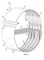
FIG. 3 is an illustration of two half fuselage barrel sections about to be joined together. -
FIG. 4 is an illustration similar toFIG. 3 but showing the two half barrel sections having been joined together by longitudinal splice joints. -
FIG. 5 is an illustration of an interior view in the direction designated asFIG. 5 inFIG. 4 for a bonded joint. -
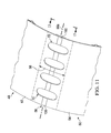
FIG. 6 is an illustration of a sectional view taken along the line 6-6 inFIG. 5 , the window frames and frame sections not shown for clarity for one form of the bonded splice joint. -
FIG. 6A is an illustration of the area designated asFIG. 6A inFIG. 6 . -
FIG. 6B is an illustration of the area designated asFIG. 6B inFIG. 6 . -
FIG. 6C is an illustration of the area designated asFIG. 6C inFIG. 6B . -
FIG. 7 is an illustration of a sectional view similar toFIG. 6 but showing an alternate form of the bonded splice joint. -
FIG. 7A is an illustration of the area designated asFIG. 7A inFIG. 7 . -
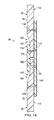
FIG. 8 is an illustration of an exterior side view of a fuselage showing barrel sections joined together by one form of a mechanical splice joint. -
FIG. 9 is an illustration of the interior side of the fuselage shown inFIG. 8 , with sections joined together by one form of a mechanical splice, prior to installation of frame splices. -
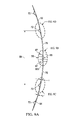
FIG. 9A is an illustration of a sectional view taken along theline 9A-9A inFIG. 9 . -
FIG. 9B is an illustration of the area designated asFIG. 9B inFIG. 9A -
FIG. 9C is an illustration of the area designated asFIG. 9C inFIG. 9A . -
FIG. 9D is an illustration of the area designated asFIG. 9D inFIG. 9A . -
FIG. 10 is an illustration similar toFIG. 9 , but with frame splices having been installed. -
FIG. 11 is an illustration of a perspective view of the exterior side of a fuselage in which the barrel sections are joined together using an alternate form of a mechanical splice joint. -
FIG. 12 is an illustration of the interior side of the fuselage shown inFIG. 11 . -
FIG. 13 is an illustration of an isometric view in the direction shown asFIG. 13 inFIG. 11 . -
FIG. 14 is an illustration of a sectional view taken along the line 14-14 inFIG. 12 . -
FIG. 15 is an illustration of a flow diagram of a method of fabricating a fuselage barrel assembly using one form of a bonded splice joint. -
FIG. 16 is an illustration of a flow diagram of a method of fabricating a fuselage barrel assembly using an alternate form of a bonded splice joint. -
FIG. 17 is an illustration of a flow diagram of a method of fabricating a fuselage barrel assembly employing one form of a mechanically fastened splice joint. -
FIG. 18 is an illustration of a flow diagram of a method of fabricating a fuselage barrel assembly using an alternate form of a mechanically fastened splice joint. - The disclosed embodiments involve the fabrication of a barrel-type structure, such as an aircraft fuselage having a composite outer skin, in which panelized fuselage sections are joined together by longitudinal splice joints. The embodiments, may however, have application in fields other than the aerospace industry. Referring now to
FIGS. 1 and 2 , embodiments of the disclosure may be used in the context of an aircraft manufacturing andservice method 20 as shown inFIG. 1 and anaircraft 22 as shown inFIG. 2 . During pre-production,exemplary method 20 may include specification anddesign 24 of theaircraft 22 andmaterial procurement 26. During production, component andsubassembly manufacturing 28 andsystem integration 30 of theaircraft 22 takes place. Thereafter, theaircraft 22 may go through certification anddelivery 32 in order to be placed inservice 34. While in service by a customer, theaircraft 22 is scheduled for routine maintenance andservice 36, which may also include modification, reconfiguration, refurbishment, and so on. - Each of the processes of
method 20 may be performed or carried out by a system integrator, a third party, and/or an operator (e.g., a customer). For the purposes of this description, a system integrator may include without limitation any number of aircraft manufacturers and major-system subcontractors; a third party may include without limitation any number of vendors, subcontractors, and suppliers; and an operator may be an airline, leasing company, military entity, service organization, and so on. - As shown in
FIG. 2 , theaircraft 22 produced byexemplary method 20 may include anairframe 38 with a plurality ofsystems 40 and an interior 42. Examples of high-level systems 40 include one or more of apropulsion system 60, anelectrical system 62, ahydraulic system 64, and anenvironmental system 66. Any number of other systems may be included. Theairframe 38 includes a fuselage 44,wings 46 and horizontal andvertical stabilizers 47. The fuselage 44 may comprise one ormore barrel assemblies 45 each of which includes anupper barrel section 48 and alower barrel section 50. Each of thebarrel sections barrel assembly 45.Barrel sections upper skin section 52 and alower skin section 54 that are joined together by two longitudinal splice joints 56 to form a compositeouter skin 73 of thebarrel assembly 45. The splice joints 56 are located withinwindow belts 58 of the fuselage 44 where one or more windows (not shown) may be located. As will be discussed in more detail below, the disclosedsplice joints 56 are located within the skin ply pads-ups used to reinforce the windows in thewindow belts 58, thereby reducing the weight of theaircraft 22 and improving manufacturing efficiency. - Systems and methods embodied herein may be employed during any one or more of the stages of the production and
service method 20. For example, components or subassemblies corresponding toproduction process 28 may be fabricated or manufactured in a manner similar to components or subassemblies produced while theaircraft 22 is in service. Also, one or more apparatus embodiments, method embodiments, or a combination thereof may be utilized during the production stages 28 and 30, for example, by substantially expediting assembly of or reducing the cost of anaircraft 22. Similarly, one or more of apparatus embodiments, method embodiments, or a combination thereof may be utilized while theaircraft 22 is in service, for example and without limitation, to maintenance andservice 36. - Referring now to
FIGS. 3 and4 , thefuselage barrel assembly 45 broadly comprises upper andlower barrel sections barrel half sections barrel half sections splice joints 56 respectively on opposite left and right sides of thebarrel assembly 45. Each of the splice joints 56 is located within an area of awindow belt 58 where one ormore windows 70 may be located, and theouter skin 73 of thefuselage barrel assembly 45 is padded up to an increased thickness. - In the illustrated example, the
center line 56a of the splice joint 56 passes through approximately the middle of a row of thewindows 70. While thefuselage barrel assembly 45 is shown as having a generally circular cross sectional shape, other cross sectional shapes are possible. Also, while thebarrel sections piece barrel assembly 45, it should be noted here that the upper and lower barrel halves 48, 50 may each themselves be formed of two or more sections. However, the illustratedbarrel assembly 45 employing only two sections orhalves barrel sections barrel half sections window belt 58. Thus, as used herein, "splice joint" is intended to include a wide range of joint configurations, including but not limited to tapered lap joints, step lap joints, finger joints and joints employing individual splice elements to join the upper and lowerbarrel half sections - The
barrel half sections composite skin sections outer skin 73 of thebarrel assembly 45. The thickness or gauge (not shown) of theskin sections 52 is greater in the area of thewindow belt 58 in order to reinforce thewindow cutouts 70a. This increased skin thickness in the area of thewindow belts 58, achieved by ply pad-ups in the upper andlower skin sections skin sections frames 74 and longitudinally extending, circumferentially spacedstringers 72 which are attached to theskin sections frames 74 and are partially supported bystanchions 78 connected to theframes 74. Other interior framework configurations are possible. - Referring now to
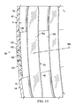
FIG. 5 , each of thewindows 70 includes awindow cutout 70a surrounded by a reinforcingwindow frame 80 attached to the upper andlower skin sections windows 70 is located between twoadjacent stringers 72 and two adjacentframe splice segments 82 that are attached to theframes 74 by frame splices 84. The splice joint 56 between the upper andlower skin sections window belt 58 which extends between thestringers 72. The centerlines of thestringers 72 are indicated at 72a. The splice joint 56 may or may not extend the full height of thewindow belt 58. In the illustrated example, thecenterline 56a of the splice joint 56 substantially coincides with the centerline of thewindow belt 58, however in other embodiments, these two centerlines may be somewhat offset from each other. - Referring to
FIGS. 6 and 6A , the upper andlower skin sections ups 75 within thewindow belt 58 extending betweenadjacent stringers 72, resulting in a skin thickness or gauge "t" that is greater within thewindow belt 58 than the skin thickness "t1 " above and below thewindow belt 58. The pad-ups 75 extend essentially the full height of thewindow belt 58, between thestringers 72. The splice joint 56 lies within the pad-ups 75 used to reinforce thewindow cutouts 70a, thus taking advantage of the increased skin thickness "t" needed to reinforce thewindow cutouts 70a, to carry loads between the upper andlower skin sections window cutouts 70a within thewindow belt 58, by locating the splice joint 56 within thewindow belt 58, thereby obviating the need for a separate pad-up for the splice joint 56. In this example, the splice joint 56 is a bonded tapered lap joint, however, as previously mentioned, other joint configurations are possible. -
FIGS. 6B and 6C illustrate additional details of the bonded splice joint 56 shown inFIG. 6 . The bonded splice joint 56 is formed by overlappingedges skin sections FIG. 6C , each of theskin sections tapered edges ply steps 88 forming a step lap joint configuration. Each of the ply steps 88 may comprise one ormore plies 86 formed by ply drop-offs. The thickness "t" of theskin sections FIG. 6C ), and is selected such that theskin 73 and the splice joint 56 can carry all necessary loads in the area of thewindow belt 58. Each of the ply steps 88 forms abonding surface 90. The ply drop-off or taper ratio of theedges 52a, 52b may be selected to suit the particular application, and may determine, at least in part, the total amount ofbond surface 90 that is available to create a load-carrying bonded joint between the upper andlower skin sections bond surfaces 90 that are sufficient in area to give the splice joint 56 enough strength within thewindow belt 58 to both adequately reinforce thewindow cutouts 70a, and to transfer loads between theskin sections - Attention is now directed to
FIGS. 7 and 7A which illustrate an alternate embodiment of the bonded splice joint 56. In this example, theedges skin sections tapered splice strap 92 which may comprise multiple plies 94 (FIG. 7A ) of a suitable fiber reinforced resin, similar to the plies of theskin sections FIG. 7A , one ormore plies 96 of theouter edges skin sections centerline 56a of the joint 56, forming a butt joint 97 overlying thesplice strap 92. In other embodiments however, theplies 96 may not abut each other, rather there may be a slight gap (not shown) between theplies 96 at theouter edges 52a, 52b. In the case of the embodiments shown inFIG. 5-7A , mechanical fasteners 87 (FIG. 5 ) used to attach thewindow frames 80 and the frame splices 82 to the upper andlower skins laminate skin sections splice strap 92 forms step lap joints or finger joints with the upper andlower skin sections - As an alternative to the method described above in which the splice joint 56 between the upper and
lower skin sections FIGS. 8-10 , longitudinal splice joint 56 located within thewindow belt 58 uses suitablemechanical fasteners 87 to join the upper andlower skin section FIG. 8 , thecenterline 56a of the splice joint 56 passes substantially through the center of thewindow cutouts 70a, within thewindow belt 58. The upper andlower skin sections joint line 85. A slight gap (not shown) may be present between theskin sections joint line 85. As will become apparent below, thelaminated skin sections window belt 58 in order to reinforce thewindow cutouts 70a, similar to the embodiments previously described in connection withFIGS. 5-7 . - Referring particularly to
FIGS. 9 ,9A ,9B ,9C and 9D ,window frames 80 are formed of a suitable rigid material such as a metal or a composite. Each of the window frames 80 includes aframe portion 80a surrounding and reinforcing the window cut-outs 70a, and longitudinalsplice plate portions 80b formed integral with theframe portions 80a. Thesplice plate portions 80b are substantially aligned with thecenterline 56a and cover thejoint line 85 between the upper andlower skins window frames 80 form a series ofinternal splice plates 93 respectively within theframe bays 65 that form a single shear joint between the upper andlower skin sections joint line 85. As best seen inFIGS. 9A ,9B ,9C and 9D , the upper andlower skin sections ups 75 within thewindow belt 58 extending betweenadjacent stringers 72, resulting in a skin thickness or gauge "t" that is greater within thewindow belt 58 than the skin thickness "t1" above and below thewindow belt 58. The pad-ups 75 extend essentially the full height of thewindow belt 58, between thestringers 72. The splice joint 56 formed by thewindow frames 80, including thesplice plate portions 80b, lies within the region including with pad-ups 75, thus taking advantage of the increased skin thickness "t" needed to reinforce thewindows 70, to carry loads between the upper andlower skin sections FIG. 9 ,suitable fasteners 87 attach thewindow frames 80, including thesplice plate portions 80b, to both the upper andlower skin sections - Referring particularly to
FIG. 9 , the windowframe splice extensions 80b ofwindow frames 80 may be slightly spaced apart to formgaps 105 between adjacent window frames. Agap 95 is also present between theframes 74 of the upper andlower barrel sections FIG. 10 , in order to connect theframes 74 of the upper andlower barrel sections frames 74, coveringgaps 95 and 105 (FIG. 9 ). The frame splices 98 are also fastened to the upper andlower skin sections -
FIGS. 11-14 illustrate another embodiment of the splice joint 56 employing mechanical fastening which may reduce any centroid eccentricities and/or bending moments that may be present in the single shear splice joint shown inFIGS. 8-10 . As in the case of the previous examples, the upper andlower skin sections window belt 58 for window cutout and splice joint reinforcement. - Referring particularly to
FIGS. 13 and14 , the adjacent edges of the upper andlower skin sections external recesses window belt 58. The edges of the upper andlower skin sections joint line 106 between the upper andlower skin sections external splice plate 100 is located within the taperedrecesses lower skin sections FIG. 14 ) of theexternal splice plate 100 may be generally flush with the skin outer mold line (OML) 112. Theexternal splice plate 100 overlies thejoint line 106 of the upper andlower skin sections internal splice plates 108 which lie flush against the IML (inner mold line) 115 of theskin sections joint line 106. Thus, the upper andlower skin sections external splice plate 100 and theinternal splice plates 108, forming a double shear joint between the upper andlower skin sections Suitable fasteners 110 fasten the external andinternal splice plates lower skin sections FIG. 14 ) that may exist between theexternal splice plate 108 and theskin sections recesses - Attention is now directed to
FIG. 15 which broadly illustrates the steps of a method of fabricating afuselage barrel assembly 45 of the type shown inFIGS. 3 and4 , using the bonding technique previously discussed in connection withFIGS. 5 ,6 and 6A . The upper andlower barrel sections skin sections sequence 116, theupper skin section 52 andstringers 72 are assembled at 120. At 122, the assembledupper skin section 52 andstringers 72 are co-cured using conventional techniques such as autoclave curing although out-of-autoclave curing may be possible. Other techniques for assembling theupper skin section 52 and thestringers 72 are possible, including the use of mechanical fasteners. At 124, theframes 74 and other mechanically fastened components such as cutout reinforcement plates (not shown), are attached using mechanical fasteners or other suitable means, to the assembly of theupper skin section 52 and thestringers 72. - The
lower barrel section 50 is assembled in asequence 118 similar manner to thesequence 116 described above. At 126, thelower skin section 54 and associatedstringers 72 are assembled, and at 128, the assembledlower skin section 54 andstringers 72 are co-cured. Then, atstep 130, theframes 74 and any other mechanically fastened components, such as skin cutout reinforcement parts, are attached, using fasteners or other suitable means, to the assembly of thelower skin section 54 and thestringers 72. The upper andlower barrel sections step 132, a suitable bonding adhesive is applied to the mating surfaces of the splice joint 56. Specifically, the bonding adhesive may be applied to the opposing bond surfaces 90 (FIG. 6C ) of the taperededges lower barrel sections FIG. 6 . It should be noted here that step 132 involving the application of the adhesive to the joint surfaces may be performed after the upper and lower barrel halves have been located in the splice assembly fixture instep 134. - At 136, the upper and
lower barrel sections window belt 58. Out-of-autoclave curing of the bonding adhesive may also be possible. Atstep 138,window openings 70a may be cutout in the upper andlower skin sections step 140, frame splice segments and frame splices 82, 84 respectively, are installed in order to connect theframe sections 74 of the upper and lower barrel sections. -
FIG. 16 illustrates the overall steps of a method of fabricating abarrel assembly 45 using a splice joint 56 employing the bondedsplice strap 92 previously discussed in connection withFIGS. 7 and 7A . The upper andlower barrel assemblies FIG. 15 . Atstep 142, thesplice strap 92 is fabricated, and at 144 a suitable bonding adhesive is applied to the splice joint surfaces, including thesplice strap 92. At 146, the upper andlower barrel sections lower skin sections splice strap 92. At 148, thebarrel sections splice strap 92, in a secondary bonding operation in which thegreen splice strap 92 along with the bonding adhesive is cured, for example in an autoclave, although out-of-autoclave curing may also be possible. Atstep 150,window cutout openings 70a may be formed in the upper andlower skin sections frame splice segments 82 and frame splices 84 are installed to connect theframe sections 74, and the window frames are installed. -
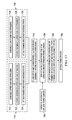
FIG. 17 broadly illustrates the steps of a method of fabricating thebarrel assembly 45, in which the splice joint 56 is formed using mechanical fasteners andinternal window frames 80 havingsplice plate portions 80b previously described in connection withFIGS. 8-10 . In this embodiment, the upper andlower barrel sections sequences FIGS. 15 and16 . At 154, the upper andlower barrel sections lower skin sections window frames 80 havingsplice plate portions 80b are fabricated. At 158, the upper andlower barrel sections FIGS. 8-10 . At 160, thewindow openings 70a may be cutout in the upper andlower skin sections window openings 70a may be formed prior to step 154 by trimming each side of thebarrel sections frame sections 74. -
FIG. 18 illustrates the overall steps of a method of fabricating thebarrel assembly 45 using a mechanical splice joint 56 of the type previously described in connection withFIGS. 11-14 that employs external andinternal splice plates lower barrel sections lower barrel sections lower skin sections exterior splice plate 100 is fabricated and atstep 168 theinterior splice plates 108 are fabricated. At 170, the exterior andinterior splice plates skin sections window openings 70a may be cutout in the upper andlower skins window openings 70a may be formed prior to step 164 by trimming each side of thebarrel sections frame sections 74. - The description of the different advantageous embodiments has been presented for purposes of illustration and description, and is not intended to be exhaustive or limited to the embodiments in the form disclosed. Many modifications and variations will be apparent to those of ordinary skill in the art. Further, different advantageous embodiments may provide different advantages as compared to other advantageous embodiments. The embodiment or embodiments selected are chosen and described in order to best explain the principles of the embodiments, the practical application, and to enable others of ordinary skill in the art to understand the disclosure for various embodiments with various modifications as are suited to the particular use contemplated.
Claims (15)
- A fuselage, comprising:a composite skin including upper 52 and lower 54 composite skin sections;a window belt 58 in the composite skin, the window belt including at least one window opening in the composite skin; anda longitudinal splice joint 56 along the window belt joining the upper and lower skins sections together.
- The fuselage of claim 1, wherein the splice joint 56 includes an adhesive bond between the upper and lower skin sections and wherein each of the upper and lower skin sections include laminated resin plies with ply drop-offs each forming bonding surfaces along the splice joint.
- The fuselage of claim 1 or claim 2, wherein the upper and lower skin sections have overlapping tapered edges joined together along the splice joint.
- The fuselage of any of the preceding claims wherein the splice joint includes a composite splice strap bonded to each of the upper and lower skin sections.
- The fuselage of any of the preceding claims, wherein:the composite skin includes an area of increased thickness within the window belt, andthe splice joint is located within the area of increased thickness of the skin and wherein the window is located in within the area of increased thickness of the skin.
- The fuselage of any of the preceding claims, wherein each of the upper and lower skin sections is a half barrel.
- The fuselage of any of the preceding claims, further comprising:first and second longitudinally extending stringers attached to the composite skin, wherein the splice joint and the window are located between the first and second stringers.
- The fuselage of any of the preceding claims, wherein:the splice joint has a height, andthe window has a height greater than the height of the splice joint.
- The fuselage of any of the preceding claims, wherein the splice joint includes at least a first splice plate fastened to the upper and lower skin sections and wherein:the upper and lower skin sections include inside surfaces and outside surfaces, andthe first splice plate is fastened to the upper and lower skin sections by mechanical fasteners, the first splice plate being located inside the fuselage and engaging the inside surfaces of the upper and lower skin sections.
- The fuselage of any of the preceding claims, wherein the splice joint includes:a window frame substantially surrounding the window opening and attached to the upper and lower skin sections, andthe window frame includes splice plate portions extending longitudinally along the window belt and fastened to the upper and lower skin sections and wherein:the upper and lower skin sections include adjacent interior surfaces extending longitudinally along a joint line, andthe splice plate portions are attached to the adjacent inside surfaces and span the joint line.
- The fuselage of any of the preceding claims, wherein:the window belt includes a longitudinal centerline,each of the upper and lower skin sections is a barrel half, andthe splice joint joins the barrel halves along a centerline of the window belt.
- A method of making a fuselage barrel assembly, comprising:fabricating an upper barrel half having an upper composite skin;fabricating a lower barrel half having a lower composite skin;placing each of the upper and lower barrel halves in a splice assembly feature, including co-locating edges of the upper and lower skins; andsplicing together the edges of the upper and lower skins.
- The method of claim 12, wherein splicing the edges of the upper and lower skins is performed by adhesively bonding the edges together.
- The method of claim 12 and claim 13, wherein splicing the edges of the upper and lower skins is performed by co-curing the upper and lower skins.
- The method of any of the preceding claims, wherein splicing the edges of the upper and lower skins is performed by fastening splice plates between the upper and lower skins and wherein splicing the edges includes overlapping and joining the edges of the upper and lower skins, and wherein:fabricating the upper and lower barrel halves includes forming a longitudinal recess in the edges of the upper and lower skins, andsplicing the edges together includes placing a splice plate in the recess and fastening the splice plate to each of the upper and lower skins.
Applications Claiming Priority (1)
| Application Number | Priority Date | Filing Date | Title |
|---|---|---|---|
| US13/540,005 US8939406B2 (en) | 2012-07-02 | 2012-07-02 | Joining composite fuselage sections along window belts |
Publications (3)
| Publication Number | Publication Date |
|---|---|
| EP2682340A2 true EP2682340A2 (en) | 2014-01-08 |
| EP2682340A3 EP2682340A3 (en) | 2018-01-03 |
| EP2682340B1 EP2682340B1 (en) | 2021-12-08 |
Family
ID=48703176
Family Applications (1)
| Application Number | Title | Priority Date | Filing Date |
|---|---|---|---|
| EP13173489.9A Active EP2682340B1 (en) | 2012-07-02 | 2013-06-25 | Joining composite fuselage sections along window belts |
Country Status (9)
| Country | Link |
|---|---|
| US (1) | US8939406B2 (en) |
| EP (1) | EP2682340B1 (en) |
| JP (1) | JP6250312B2 (en) |
| KR (1) | KR102044558B1 (en) |
| CN (1) | CN103523200B (en) |
| AU (1) | AU2013205541B2 (en) |
| CA (1) | CA2815528C (en) |
| ES (1) | ES2908176T3 (en) |
| RU (1) | RU2628262C2 (en) |
Cited By (2)
| Publication number | Priority date | Publication date | Assignee | Title |
|---|---|---|---|---|
| EP3263443A1 (en) * | 2016-06-30 | 2018-01-03 | Airbus Operations GmbH | Window frame system, window frame attachment system and vehicle hull window frame attachment system |
| EP3441300A1 (en) * | 2017-08-07 | 2019-02-13 | The Boeing Company | Pressure bulkhead system |
Families Citing this family (13)
| Publication number | Priority date | Publication date | Assignee | Title |
|---|---|---|---|---|
| US7325771B2 (en) * | 2004-09-23 | 2008-02-05 | The Boeing Company | Splice joints for composite aircraft fuselages and other structures |
| US9314875B2 (en) * | 2007-05-31 | 2016-04-19 | Airbus Operations Gmbh | Method for producing a composite skin in the field of aeronautics and astronautics |
| ES2401517B1 (en) * | 2011-05-31 | 2014-06-18 | Airbus Operations S.L. | AIRCRAFT NOTEBOOK IN COMPOSITE MATERIAL. |
| EP3061684B1 (en) * | 2013-10-17 | 2019-01-30 | Airbus Operations GmbH | Method of joining panels for an airframe |
| US10112695B2 (en) * | 2015-08-20 | 2018-10-30 | Georgian Aerospace Llc | Receptacle, payload assembly and related methods for an aircraft |
| US10450870B2 (en) | 2016-02-09 | 2019-10-22 | General Electric Company | Frangible gas turbine engine airfoil |
| US10308342B2 (en) * | 2016-09-07 | 2019-06-04 | The Boeing Company | Method of repairing damage to fuselage barrel and associated apparatus and system |
| US20190389096A1 (en) * | 2017-02-22 | 2019-12-26 | Mitsubishi Heavy Industries, Ltd. | Composite material and method for manufacturing composite material |
| FR3072645B1 (en) * | 2017-10-25 | 2021-12-17 | Airbus | AIRCRAFT FUSELAGE INCLUDING AT LEAST TWO TRANSPARENT WALLS INTERIED BETWEEN TWO UPPER AND LOWER PORTIONS OF THE FUSELAGE |
| DE102017128496A1 (en) * | 2017-11-30 | 2019-06-06 | Airbus Operations Gmbh | Method for producing a structural section of a vehicle |
| RU2733309C1 (en) * | 2019-12-23 | 2020-10-01 | Акционерное общество «Информационные спутниковые системы» имени академика М.Ф.Решетнёва» | Reinforcement unit for frame of force lattice construction of housing from polymer composite materials (versions) |
| EP3978358A1 (en) * | 2020-09-30 | 2022-04-06 | The Boeing Company | Aircraft fuselage longitudinal splice for joining half barrel fuselage sections and other spliced fuselage sections |
| US11911978B2 (en) * | 2021-05-07 | 2024-02-27 | The Boeing Company | Methods and associated systems for manufacturing composite barrel structures |
Family Cites Families (31)
| Publication number | Priority date | Publication date | Assignee | Title |
|---|---|---|---|---|
| US2327636A (en) * | 1943-08-24 | Aircraft fuselage construction | ||
| US1368428A (en) * | 1919-06-11 | 1921-02-15 | Curtiss Aeroplane & Motor Co | Airplane-fuselage |
| US4450661A (en) | 1981-09-30 | 1984-05-29 | The Boeing Company | Composite structures window belt and method of making |
| US5429326A (en) | 1992-07-09 | 1995-07-04 | Structural Laminates Company | Spliced laminate for aircraft fuselage |
| FR2710871B1 (en) * | 1993-10-07 | 1995-12-01 | France Etat Armement | Method of assembling elements of composite material and elements joining them together. |
| DE4408476C2 (en) * | 1994-03-14 | 1996-04-11 | Daimler Benz Aerospace Airbus | Fuselage skin for an airplane |
| NL1024077C2 (en) * | 2003-08-08 | 2005-02-10 | Stork Fokker Aesp Bv | Method for manufacturing a laminate with mutually offset layers. |
| US7527222B2 (en) * | 2004-04-06 | 2009-05-05 | The Boeing Company | Composite barrel sections for aircraft fuselages and other structures, and methods and systems for manufacturing such barrel sections |
| US7325771B2 (en) | 2004-09-23 | 2008-02-05 | The Boeing Company | Splice joints for composite aircraft fuselages and other structures |
| US7530531B2 (en) | 2004-10-04 | 2009-05-12 | The Boeing Company | Apparatus and methods for installing an aircraft window panel |
| US7823832B2 (en) | 2004-10-04 | 2010-11-02 | The Boeing Company | Injection-molded window panel and related methods |
| US7802413B2 (en) | 2004-10-04 | 2010-09-28 | The Boeing Company | Apparatus and methods for reinforcing a structural panel |
| US7118069B2 (en) | 2004-12-02 | 2006-10-10 | The Boeing Company | Integrated window belt system for aircraft cabins |
| US7438263B2 (en) | 2005-09-09 | 2008-10-21 | The Boeing Company | Optimal aircraft window shape for noise control |
| DE102006025930B4 (en) * | 2006-06-02 | 2008-09-11 | Airbus Deutschland Gmbh | Hull structure and method of making a hull structure |
| EP2032429B1 (en) * | 2006-06-28 | 2010-08-11 | Airbus Operations GmbH | Aircraft-fuselage assembly concept |
| FR2906008B1 (en) * | 2006-09-15 | 2008-11-07 | Airbus France Sa | SMOOTH CHEST AND ORBITAL JUNCTION DEVICE |
| US7735779B2 (en) * | 2006-11-02 | 2010-06-15 | The Boeing Company | Optimized fuselage structure |
| US7861970B2 (en) * | 2006-11-02 | 2011-01-04 | The Boeing Company | Fuselage structure including an integrated fuselage stanchion |
| US20100187352A1 (en) * | 2007-02-23 | 2010-07-29 | Mr. Michael Yavilevich | Multi deck aircraft |
| DE102007046478B4 (en) * | 2007-05-23 | 2012-08-02 | Airbus Operations Gmbh | Sheet metal laminate, in particular for fuselage skin panels for aircraft |
| US8752293B2 (en) * | 2007-12-07 | 2014-06-17 | The Boeing Company | Method of fabricating structures using composite modules and structures made thereby |
| FR2928343B1 (en) * | 2008-03-10 | 2010-08-20 | Airbus France | PORCH PANEL AND METHOD OF MANUFACTURING SUCH AN AIRCRAFT PANEL COMPRISING A DOOR PANEL |
| US8038099B2 (en) * | 2008-04-30 | 2011-10-18 | The Boeing Company | Bonded metal fuselage and method for making the same |
| US7967250B2 (en) * | 2008-05-12 | 2011-06-28 | EMBRAER—Empresa Brasileira de Aeronáutica | Hybrid aircraft fuselage structural components and methods of making same |
| FR2936495B1 (en) * | 2008-09-30 | 2011-06-03 | Airbus France | ASSEMBLY OF PANELS FOR AIRCRAFT FUSELAGE. |
| DE102009009491A1 (en) * | 2009-02-18 | 2010-09-09 | Airbus Deutschland Gmbh | Method for producing a shell body |
| DE102009013585B4 (en) * | 2009-03-17 | 2012-01-26 | Airbus Operations Gmbh | Fuselage cell structure for a hybrid aircraft |
| US20120160966A1 (en) * | 2009-11-23 | 2012-06-28 | Applied Nanostructured Solutions, Llc | Cnt-tailored composite space-based structures |
| CA2788948C (en) * | 2010-02-05 | 2019-03-26 | Learjet Inc. | System and method for fabricating a composite material assembly |
| US8616500B2 (en) * | 2011-03-04 | 2013-12-31 | The Boeing Company | Diamond shaped window for composite and/or metallic airframe |
-
2012
- 2012-07-02 US US13/540,005 patent/US8939406B2/en active Active
-
2013
- 2013-04-30 AU AU2013205541A patent/AU2013205541B2/en active Active
- 2013-05-06 KR KR1020130050897A patent/KR102044558B1/en active IP Right Grant
- 2013-05-09 CA CA2815528A patent/CA2815528C/en active Active
- 2013-06-25 ES ES13173489T patent/ES2908176T3/en active Active
- 2013-06-25 EP EP13173489.9A patent/EP2682340B1/en active Active
- 2013-06-26 JP JP2013134141A patent/JP6250312B2/en active Active
- 2013-07-01 RU RU2013129951A patent/RU2628262C2/en active
- 2013-07-02 CN CN201310273216.0A patent/CN103523200B/en active Active
Non-Patent Citations (1)
| Title |
|---|
| None |
Cited By (4)
| Publication number | Priority date | Publication date | Assignee | Title |
|---|---|---|---|---|
| EP3263443A1 (en) * | 2016-06-30 | 2018-01-03 | Airbus Operations GmbH | Window frame system, window frame attachment system and vehicle hull window frame attachment system |
| US10549837B2 (en) | 2016-06-30 | 2020-02-04 | Airbus Operations Gmbh | Window frame system, window frame attachment system and vehicle hull window frame attachment system |
| EP3441300A1 (en) * | 2017-08-07 | 2019-02-13 | The Boeing Company | Pressure bulkhead system |
| US10926858B2 (en) | 2017-08-07 | 2021-02-23 | The Boeing Company | Pressure bulkhead system |
Also Published As
| Publication number | Publication date |
|---|---|
| AU2013205541B2 (en) | 2016-10-20 |
| RU2628262C2 (en) | 2017-08-15 |
| CA2815528C (en) | 2020-07-07 |
| AU2013205541A1 (en) | 2014-01-16 |
| KR102044558B1 (en) | 2019-11-13 |
| EP2682340A3 (en) | 2018-01-03 |
| CA2815528A1 (en) | 2014-01-02 |
| CN103523200B (en) | 2017-05-24 |
| US8939406B2 (en) | 2015-01-27 |
| JP6250312B2 (en) | 2017-12-20 |
| EP2682340B1 (en) | 2021-12-08 |
| US20140001311A1 (en) | 2014-01-02 |
| CN103523200A (en) | 2014-01-22 |
| ES2908176T3 (en) | 2022-04-28 |
| RU2013129951A (en) | 2015-01-10 |
| JP2014012513A (en) | 2014-01-23 |
| KR20140003999A (en) | 2014-01-10 |
Similar Documents
| Publication | Publication Date | Title |
|---|---|---|
| CA2815528C (en) | Joining composite fuselage sections along window belts | |
| US8079549B2 (en) | Monolithic integrated structural panels especially useful for aircraft structures | |
| JP6214215B2 (en) | Joined composite airfoil and manufacturing method | |
| KR101790439B1 (en) | Joint for composite wings | |
| US20210101381A1 (en) | Multi-layer metallic structure and composite-to-metal joint methods | |
| EP2444238B1 (en) | Method for joining sandwich truss core panels and composite structures produced therefrom | |
| JP5788403B2 (en) | Sandwich structure having rest mechanism and method for producing the same | |
| EP2650120B1 (en) | Multi-layer metallic structure |
Legal Events
| Date | Code | Title | Description |
|---|---|---|---|
| PUAI | Public reference made under article 153(3) epc to a published international application that has entered the european phase |
Free format text: ORIGINAL CODE: 0009012 |
|
| 17P | Request for examination filed |
Effective date: 20130625 |
|
| AK | Designated contracting states |
Kind code of ref document: A2 Designated state(s): AL AT BE BG CH CY CZ DE DK EE ES FI FR GB GR HR HU IE IS IT LI LT LU LV MC MK MT NL NO PL PT RO RS SE SI SK SM TR |
|
| AX | Request for extension of the european patent |
Extension state: BA ME |
|
| PUAL | Search report despatched |
Free format text: ORIGINAL CODE: 0009013 |
|
| AK | Designated contracting states |
Kind code of ref document: A3 Designated state(s): AL AT BE BG CH CY CZ DE DK EE ES FI FR GB GR HR HU IE IS IT LI LT LU LV MC MK MT NL NO PL PT RO RS SE SI SK SM TR |
|
| AX | Request for extension of the european patent |
Extension state: BA ME |
|
| RIC1 | Information provided on ipc code assigned before grant |
Ipc: B64C 1/06 20060101AFI20171130BHEP Ipc: B64F 5/00 20170101ALI20171130BHEP |
|
| STAA | Information on the status of an ep patent application or granted ep patent |
Free format text: STATUS: EXAMINATION IS IN PROGRESS |
|
| 17Q | First examination report despatched |
Effective date: 20190819 |
|
| STAA | Information on the status of an ep patent application or granted ep patent |
Free format text: STATUS: EXAMINATION IS IN PROGRESS |
|
| GRAJ | Information related to disapproval of communication of intention to grant by the applicant or resumption of examination proceedings by the epo deleted |
Free format text: ORIGINAL CODE: EPIDOSDIGR1 |
|
| GRAP | Despatch of communication of intention to grant a patent |
Free format text: ORIGINAL CODE: EPIDOSNIGR1 |
|
| GRAP | Despatch of communication of intention to grant a patent |
Free format text: ORIGINAL CODE: EPIDOSNIGR1 |
|
| STAA | Information on the status of an ep patent application or granted ep patent |
Free format text: STATUS: GRANT OF PATENT IS INTENDED |
|
| INTG | Intention to grant announced |
Effective date: 20210630 |
|
| GRAS | Grant fee paid |
Free format text: ORIGINAL CODE: EPIDOSNIGR3 |
|
| GRAA | (expected) grant |
Free format text: ORIGINAL CODE: 0009210 |
|
| STAA | Information on the status of an ep patent application or granted ep patent |
Free format text: STATUS: THE PATENT HAS BEEN GRANTED |
|
| AK | Designated contracting states |
Kind code of ref document: B1 Designated state(s): AL AT BE BG CH CY CZ DE DK EE ES FI FR GB GR HR HU IE IS IT LI LT LU LV MC MK MT NL NO PL PT RO RS SE SI SK SM TR |
|
| REG | Reference to a national code |
Ref country code: GB Ref legal event code: FG4D |
|
| REG | Reference to a national code |
Ref country code: AT Ref legal event code: REF Ref document number: 1453581 Country of ref document: AT Kind code of ref document: T Effective date: 20211215 Ref country code: CH Ref legal event code: EP |
|
| REG | Reference to a national code |
Ref country code: DE Ref legal event code: R096 Ref document number: 602013080321 Country of ref document: DE |
|
| REG | Reference to a national code |
Ref country code: IE Ref legal event code: FG4D |
|
| REG | Reference to a national code |
Ref country code: LT Ref legal event code: MG9D |
|
| REG | Reference to a national code |
Ref country code: NL Ref legal event code: MP Effective date: 20211208 |
|
| REG | Reference to a national code |
Ref country code: ES Ref legal event code: FG2A Ref document number: 2908176 Country of ref document: ES Kind code of ref document: T3 Effective date: 20220428 |
|
| PG25 | Lapsed in a contracting state [announced via postgrant information from national office to epo] |
Ref country code: RS Free format text: LAPSE BECAUSE OF FAILURE TO SUBMIT A TRANSLATION OF THE DESCRIPTION OR TO PAY THE FEE WITHIN THE PRESCRIBED TIME-LIMIT Effective date: 20211208 Ref country code: LT Free format text: LAPSE BECAUSE OF FAILURE TO SUBMIT A TRANSLATION OF THE DESCRIPTION OR TO PAY THE FEE WITHIN THE PRESCRIBED TIME-LIMIT Effective date: 20211208 Ref country code: FI Free format text: LAPSE BECAUSE OF FAILURE TO SUBMIT A TRANSLATION OF THE DESCRIPTION OR TO PAY THE FEE WITHIN THE PRESCRIBED TIME-LIMIT Effective date: 20211208 Ref country code: BG Free format text: LAPSE BECAUSE OF FAILURE TO SUBMIT A TRANSLATION OF THE DESCRIPTION OR TO PAY THE FEE WITHIN THE PRESCRIBED TIME-LIMIT Effective date: 20220308 |
|
| REG | Reference to a national code |
Ref country code: AT Ref legal event code: MK05 Ref document number: 1453581 Country of ref document: AT Kind code of ref document: T Effective date: 20211208 |
|
| PG25 | Lapsed in a contracting state [announced via postgrant information from national office to epo] |
Ref country code: SE Free format text: LAPSE BECAUSE OF FAILURE TO SUBMIT A TRANSLATION OF THE DESCRIPTION OR TO PAY THE FEE WITHIN THE PRESCRIBED TIME-LIMIT Effective date: 20211208 Ref country code: NO Free format text: LAPSE BECAUSE OF FAILURE TO SUBMIT A TRANSLATION OF THE DESCRIPTION OR TO PAY THE FEE WITHIN THE PRESCRIBED TIME-LIMIT Effective date: 20220308 Ref country code: LV Free format text: LAPSE BECAUSE OF FAILURE TO SUBMIT A TRANSLATION OF THE DESCRIPTION OR TO PAY THE FEE WITHIN THE PRESCRIBED TIME-LIMIT Effective date: 20211208 Ref country code: HR Free format text: LAPSE BECAUSE OF FAILURE TO SUBMIT A TRANSLATION OF THE DESCRIPTION OR TO PAY THE FEE WITHIN THE PRESCRIBED TIME-LIMIT Effective date: 20211208 Ref country code: GR Free format text: LAPSE BECAUSE OF FAILURE TO SUBMIT A TRANSLATION OF THE DESCRIPTION OR TO PAY THE FEE WITHIN THE PRESCRIBED TIME-LIMIT Effective date: 20220309 |
|
| PG25 | Lapsed in a contracting state [announced via postgrant information from national office to epo] |
Ref country code: NL Free format text: LAPSE BECAUSE OF FAILURE TO SUBMIT A TRANSLATION OF THE DESCRIPTION OR TO PAY THE FEE WITHIN THE PRESCRIBED TIME-LIMIT Effective date: 20211208 |
|
| PG25 | Lapsed in a contracting state [announced via postgrant information from national office to epo] |
Ref country code: SM Free format text: LAPSE BECAUSE OF FAILURE TO SUBMIT A TRANSLATION OF THE DESCRIPTION OR TO PAY THE FEE WITHIN THE PRESCRIBED TIME-LIMIT Effective date: 20211208 Ref country code: SK Free format text: LAPSE BECAUSE OF FAILURE TO SUBMIT A TRANSLATION OF THE DESCRIPTION OR TO PAY THE FEE WITHIN THE PRESCRIBED TIME-LIMIT Effective date: 20211208 Ref country code: RO Free format text: LAPSE BECAUSE OF FAILURE TO SUBMIT A TRANSLATION OF THE DESCRIPTION OR TO PAY THE FEE WITHIN THE PRESCRIBED TIME-LIMIT Effective date: 20211208 Ref country code: PT Free format text: LAPSE BECAUSE OF FAILURE TO SUBMIT A TRANSLATION OF THE DESCRIPTION OR TO PAY THE FEE WITHIN THE PRESCRIBED TIME-LIMIT Effective date: 20220408 Ref country code: EE Free format text: LAPSE BECAUSE OF FAILURE TO SUBMIT A TRANSLATION OF THE DESCRIPTION OR TO PAY THE FEE WITHIN THE PRESCRIBED TIME-LIMIT Effective date: 20211208 Ref country code: CZ Free format text: LAPSE BECAUSE OF FAILURE TO SUBMIT A TRANSLATION OF THE DESCRIPTION OR TO PAY THE FEE WITHIN THE PRESCRIBED TIME-LIMIT Effective date: 20211208 |
|
| PG25 | Lapsed in a contracting state [announced via postgrant information from national office to epo] |
Ref country code: PL Free format text: LAPSE BECAUSE OF FAILURE TO SUBMIT A TRANSLATION OF THE DESCRIPTION OR TO PAY THE FEE WITHIN THE PRESCRIBED TIME-LIMIT Effective date: 20211208 Ref country code: AT Free format text: LAPSE BECAUSE OF FAILURE TO SUBMIT A TRANSLATION OF THE DESCRIPTION OR TO PAY THE FEE WITHIN THE PRESCRIBED TIME-LIMIT Effective date: 20211208 |
|
| REG | Reference to a national code |
Ref country code: DE Ref legal event code: R097 Ref document number: 602013080321 Country of ref document: DE |
|
| PG25 | Lapsed in a contracting state [announced via postgrant information from national office to epo] |
Ref country code: IS Free format text: LAPSE BECAUSE OF FAILURE TO SUBMIT A TRANSLATION OF THE DESCRIPTION OR TO PAY THE FEE WITHIN THE PRESCRIBED TIME-LIMIT Effective date: 20220408 |
|
| PLBE | No opposition filed within time limit |
Free format text: ORIGINAL CODE: 0009261 |
|
| STAA | Information on the status of an ep patent application or granted ep patent |
Free format text: STATUS: NO OPPOSITION FILED WITHIN TIME LIMIT |
|
| PG25 | Lapsed in a contracting state [announced via postgrant information from national office to epo] |
Ref country code: DK Free format text: LAPSE BECAUSE OF FAILURE TO SUBMIT A TRANSLATION OF THE DESCRIPTION OR TO PAY THE FEE WITHIN THE PRESCRIBED TIME-LIMIT Effective date: 20211208 Ref country code: AL Free format text: LAPSE BECAUSE OF FAILURE TO SUBMIT A TRANSLATION OF THE DESCRIPTION OR TO PAY THE FEE WITHIN THE PRESCRIBED TIME-LIMIT Effective date: 20211208 |
|
| 26N | No opposition filed |
Effective date: 20220909 |
|
| PG25 | Lapsed in a contracting state [announced via postgrant information from national office to epo] |
Ref country code: SI Free format text: LAPSE BECAUSE OF FAILURE TO SUBMIT A TRANSLATION OF THE DESCRIPTION OR TO PAY THE FEE WITHIN THE PRESCRIBED TIME-LIMIT Effective date: 20211208 |
|
| PG25 | Lapsed in a contracting state [announced via postgrant information from national office to epo] |
Ref country code: MC Free format text: LAPSE BECAUSE OF FAILURE TO SUBMIT A TRANSLATION OF THE DESCRIPTION OR TO PAY THE FEE WITHIN THE PRESCRIBED TIME-LIMIT Effective date: 20211208 |
|
| REG | Reference to a national code |
Ref country code: CH Ref legal event code: PL |
|
| REG | Reference to a national code |
Ref country code: BE Ref legal event code: MM Effective date: 20220630 |
|
| PG25 | Lapsed in a contracting state [announced via postgrant information from national office to epo] |
Ref country code: LU Free format text: LAPSE BECAUSE OF NON-PAYMENT OF DUE FEES Effective date: 20220625 Ref country code: LI Free format text: LAPSE BECAUSE OF NON-PAYMENT OF DUE FEES Effective date: 20220630 Ref country code: IE Free format text: LAPSE BECAUSE OF NON-PAYMENT OF DUE FEES Effective date: 20220625 Ref country code: CH Free format text: LAPSE BECAUSE OF NON-PAYMENT OF DUE FEES Effective date: 20220630 |
|
| PG25 | Lapsed in a contracting state [announced via postgrant information from national office to epo] |
Ref country code: IT Free format text: LAPSE BECAUSE OF FAILURE TO SUBMIT A TRANSLATION OF THE DESCRIPTION OR TO PAY THE FEE WITHIN THE PRESCRIBED TIME-LIMIT Effective date: 20211208 Ref country code: BE Free format text: LAPSE BECAUSE OF NON-PAYMENT OF DUE FEES Effective date: 20220630 |
|
| P01 | Opt-out of the competence of the unified patent court (upc) registered |
Effective date: 20230516 |
|
| PGFP | Annual fee paid to national office [announced via postgrant information from national office to epo] |
Ref country code: FR Payment date: 20230626 Year of fee payment: 11 Ref country code: DE Payment date: 20230626 Year of fee payment: 11 |
|
| PGFP | Annual fee paid to national office [announced via postgrant information from national office to epo] |
Ref country code: TR Payment date: 20230609 Year of fee payment: 11 |
|
| PGFP | Annual fee paid to national office [announced via postgrant information from national office to epo] |
Ref country code: GB Payment date: 20230627 Year of fee payment: 11 Ref country code: ES Payment date: 20230703 Year of fee payment: 11 |
|
| PG25 | Lapsed in a contracting state [announced via postgrant information from national office to epo] |
Ref country code: HU Free format text: LAPSE BECAUSE OF FAILURE TO SUBMIT A TRANSLATION OF THE DESCRIPTION OR TO PAY THE FEE WITHIN THE PRESCRIBED TIME-LIMIT; INVALID AB INITIO Effective date: 20130625 |