EP2682058A1 - Radiological imaging method and device - Google Patents
Radiological imaging method and device Download PDFInfo
- Publication number
- EP2682058A1 EP2682058A1 EP12755197.6A EP12755197A EP2682058A1 EP 2682058 A1 EP2682058 A1 EP 2682058A1 EP 12755197 A EP12755197 A EP 12755197A EP 2682058 A1 EP2682058 A1 EP 2682058A1
- Authority
- EP
- European Patent Office
- Prior art keywords
- imaging
- threshold value
- radiographic
- radiation
- state
- Prior art date
- Legal status (The legal status is an assumption and is not a legal conclusion. Google has not performed a legal analysis and makes no representation as to the accuracy of the status listed.)
- Granted
Links
Images




Classifications
-
- A—HUMAN NECESSITIES
- A61—MEDICAL OR VETERINARY SCIENCE; HYGIENE
- A61B—DIAGNOSIS; SURGERY; IDENTIFICATION
- A61B6/00—Apparatus or devices for radiation diagnosis; Apparatus or devices for radiation diagnosis combined with radiation therapy equipment
- A61B6/54—Control of apparatus or devices for radiation diagnosis
-
- A—HUMAN NECESSITIES
- A61—MEDICAL OR VETERINARY SCIENCE; HYGIENE
- A61B—DIAGNOSIS; SURGERY; IDENTIFICATION
- A61B6/00—Apparatus or devices for radiation diagnosis; Apparatus or devices for radiation diagnosis combined with radiation therapy equipment
- A61B6/02—Arrangements for diagnosis sequentially in different planes; Stereoscopic radiation diagnosis
- A61B6/022—Stereoscopic imaging
-
- A—HUMAN NECESSITIES
- A61—MEDICAL OR VETERINARY SCIENCE; HYGIENE
- A61B—DIAGNOSIS; SURGERY; IDENTIFICATION
- A61B6/00—Apparatus or devices for radiation diagnosis; Apparatus or devices for radiation diagnosis combined with radiation therapy equipment
- A61B6/04—Positioning of patients; Tiltable beds or the like
- A61B6/0407—Supports, e.g. tables or beds, for the body or parts of the body
- A61B6/0414—Supports, e.g. tables or beds, for the body or parts of the body with compression means
-
- A—HUMAN NECESSITIES
- A61—MEDICAL OR VETERINARY SCIENCE; HYGIENE
- A61B—DIAGNOSIS; SURGERY; IDENTIFICATION
- A61B6/00—Apparatus or devices for radiation diagnosis; Apparatus or devices for radiation diagnosis combined with radiation therapy equipment
- A61B6/10—Safety means specially adapted therefor
-
- A—HUMAN NECESSITIES
- A61—MEDICAL OR VETERINARY SCIENCE; HYGIENE
- A61B—DIAGNOSIS; SURGERY; IDENTIFICATION
- A61B6/00—Apparatus or devices for radiation diagnosis; Apparatus or devices for radiation diagnosis combined with radiation therapy equipment
- A61B6/50—Apparatus or devices for radiation diagnosis; Apparatus or devices for radiation diagnosis combined with radiation therapy equipment specially adapted for specific body parts; specially adapted for specific clinical applications
- A61B6/502—Apparatus or devices for radiation diagnosis; Apparatus or devices for radiation diagnosis combined with radiation therapy equipment specially adapted for specific body parts; specially adapted for specific clinical applications for diagnosis of breast, i.e. mammography
-
- A—HUMAN NECESSITIES
- A61—MEDICAL OR VETERINARY SCIENCE; HYGIENE
- A61B—DIAGNOSIS; SURGERY; IDENTIFICATION
- A61B6/00—Apparatus or devices for radiation diagnosis; Apparatus or devices for radiation diagnosis combined with radiation therapy equipment
- A61B6/54—Control of apparatus or devices for radiation diagnosis
- A61B6/542—Control of apparatus or devices for radiation diagnosis involving control of exposure
-
- A—HUMAN NECESSITIES
- A61—MEDICAL OR VETERINARY SCIENCE; HYGIENE
- A61B—DIAGNOSIS; SURGERY; IDENTIFICATION
- A61B6/00—Apparatus or devices for radiation diagnosis; Apparatus or devices for radiation diagnosis combined with radiation therapy equipment
- A61B6/58—Testing, adjusting or calibrating thereof
- A61B6/586—Detection of faults or malfunction of the device
Definitions
- the present invention relates to a radiographic imaging method and a radiographic imaging apparatus, wherein radiation is applied to the subject from each of different imaging directions to detect a radiographic image for each imaging direction.
- stereoscopic viewing utilizing parallax can be achieved by combining and displaying a plurality of images.
- Such an image that allows stereoscopic viewing (which will hereinafter be referred to as “stereoscopic image” or “stereo image”) is generated based on a plurality of images that are obtained by imaging the same subject from different directions and therefore have a parallax therebetween.
- a stereoscopic image in this manner is used not only in the fields of digital cameras and televisions but also in the field of radiographic imaging. Namely, radiation is applied to the subject from different directions, and each radiation transmitted through the subj ect is detected with a radiographic image detector to obtain a plurality of radiographic images having a parallax therebetween, and a stereoscopic image is generated based on these radiographic images (see, for example, Patent Document 1). By generating a stereoscopic image in this manner, a radiographic image that provides feel of depth can be observed, which is more suitable for diagnosis.
- a tomosynthesis imaging apparatus wherein a radiation source is moved to apply radiation to the subject from different imaging directions, similarly to a radiographic imaging apparatus for taking the above-described stereoscopic image, has been proposed (see, for example, Patent Document 2).
- This tomosynthesis imaging apparatus performs imaging operations with applying radiation to the subject from different imaging directions, as described above, and adds up a plurality of radiographic images obtained by the imaging operations to provide an image where a desired slice plane is emphasized.
- a plurality of imaging operations are performed in a state where the breast is compressed with a compression paddle.
- the compression by the compression paddle is released when the imaging sequence is stopped, as described above, then, when the imaging switch is pressed again to restart the imaging sequence and the breast is compressed again, it is almost impossible to provide the shape of the breast that is the same as the shape before the imaging sequence is stopped. Therefore, different shapes of the breast are imaged by the plurality of imaging operations and it is impossible to obtain an appropriate stereoscopic image or tomographic image.
- the subject may be a breast and the apparatus may include a compression paddle for compressing the breast, and wherein, if the period of the OFF state is not more than the threshold value, the imaging control unit may continue compression by the compression paddle as the part of the operations of the imaging sequence, or if the period of the OFF state is longer than the threshold value, the imaging control unit may release the compression by the compression paddle.
- the imaging control unit may stop the application of radiation.
- the imaging control unit may stop movement of the radiation source.
- the threshold value may be not smaller than one second and not greater than two seconds.
- the radiographic imaging apparatus may include a threshold value setting reception unit for receiving an arbitrary value set as the threshold value.
- a plurality of values for different operators may be set in advance for the threshold value.
- the movement of the radiation source can immediately be stopped when the imaging switch is turned into OFF state by the operator not accidentally but to stop the imaging sequence, thereby avoiding the situation where the radiation source hits the subject, for example.
- the threshold value can be set according to a request from each operator, thereby providing higher convenience for each operator.
- the arm 13 is C-shaped, and provided with an imaging table 14, where a breast is placed, at one end thereof and a radiation source unit 16 at the other end thereof such that the radiation source unit 16 faces the imaging table 14.
- the movement of the arm 13 in the vertical direction is controlled by an arm controller 31, which is built in the base 11.
- the imaging table 14 contains therein a radiographic image detector 15, such as a flat panel detector, and a detector controller 33, which controls reading of electric charge signals from the radiographic image detector 15, etc.
- a radiographic image detector 15 such as a flat panel detector
- a detector controller 33 which controls reading of electric charge signals from the radiographic image detector 15, etc.
- the imaging table 14 also contains therein a circuit board, etc.
- the circuit board includes a charge amplifier for converting electric charge signals read out from the radiographic image detector 15 into voltage signals, a correlated double sampling circuit for sampling the voltage signals outputted from the charge amplifier, an AD converter for converting the voltage signals into digital signals, etc.
- the radiographic image detector 15 is of a type that is repeatedly usable to record and read a radiographic image.
- the radiation detector 15 may be a so-called direct-type radiographic image detector, which directly receives the radiation and generates electric charges, or may be a so-called indirect-type radiographic image detector, which once converts the radiation into visible light, and then converts the visible light into electric charge signals.
- a so-called TFT reading system that reads out the radiographic image signal with turning on and off TFT (thin film transistor) switches, or a so-called optical reading system that reads out the radiographic image signal by applying reading light may be used; however, this is not intended to limit the invention, and any other system may be used.
- the radiation source unit 16 contains therein a radiation source 17 and a radiation source controller 32.
- the radiation source 17 includes an X-ray tube.
- the X-ray tube includes a capacitor, which is used when a high tube voltage is applied, and an anode, which emits radiation when being hit by electron beams while being rotated.
- the radiation source controller 32 controls a start-up operation and a shut-down operation of the X-ray tube of the radiation source 17, timing of application of radiation from the radiation source 17, radiation generation conditions (such as tube current, time, tube voltage, etc.) at the radiation source 17, etc.
- a compression paddle 18 disposed above the imaging table 14 for holding and compressing the breast, a support 20 for supporting the compression paddle 18, and a moving mechanism 19 for moving the support 20 in the vertical direction are disposed.
- the position and the compressing pressure of the compression paddle 18 are controlled by a compression paddle controller 34.
- the computer 2 includes a central processing unit (CPU), a storage device, such as a semiconductor memory, a hard disk, a SSD, etc., and these hardware devices form an imaging control unit 40, a radiographic image storage unit 41 and a display control unit 42, as shown in FIG. 3 .
- CPU central processing unit
- storage device such as a semiconductor memory, a hard disk, a SSD, etc.
- the imaging control unit 40 outputs predetermined control signals to the controllers 31 to 34 to control the imaging sequence of the entire system. A specific control method will be described in detail later.
- the radiographic image storage unit 41 stores two radiographic image signals detected by the radiographic image detector 15 in imaging operations from two different imaging directions.
- the display control unit 42 applies predetermined signal processing to the radiographic image signals read out from the radiographic image storage unit 41 and then displays a stereo image of the breast on the monitor 3.
- the input unit 4 is formed by a pointing device, such as a keyboard and a mouse, and receives an input by the operator, such as an input of imaging conditions.
- the imaging switch 5 is a button used to instruct to perform a series of operations of an imaging sequence including the imaging operations from two different imaging directions. While the imaging switch 5 is pressed by the operator and is in ON state, the imaging control unit 40 of the computer 2 controls the individual units so that the series of operations of the imaging sequence are performed. In a case where the imaging switch 5 is turned into OFF state due to the operator accidentally releasing the imaging switch 5 or due to chattering or electrical noise, for example, the imaging control unit 40 stops or continues part of the operations in the imaging sequence depending on the length of period of the OFF state. How the part of operations in the imaging sequence is controlled will be described in detail later.
- the monitor 3 is configured to be capable of displaying a stereo image using two radiographic image signals outputted from the computer 2.
- an arrangement for displaying a stereo image an arrangement where two radiographic images based on two radiographic image signals are displayed using two screens, and one of the radiographic images is directed to the right eye of the observer and the other of the radiographic images is directed to the left eye of the observer by using a half mirror or a polarizing glass to achieve display of a stereo image may be employed.
- the computer 2 and the monitor 3 are turned on, the breast of a subject M is placed on the imaging table 14 and the breast is compressed by the compression paddle 18 with a predetermined pressure (S10).
- the imaging control unit 40 After the start-up operation of the X-ray tube of the radiation source 17 is finished, the imaging control unit 40 performs an imaging operation to take a first radiographic image among two radiographic images forming a stereo image.
- the imaging control unit 40 reads out imaging angles ⁇ set in advance for taking a stereo image, and outputs information of the read-out imaging angles ⁇ to the arm controller 31.
- the imaging control unit 40 In the state where the arm 13 has been moved to be perpendicular to the imaging table 14 in response to the control signal outputted from the arm controller 31, the imaging control unit 40 outputs a control signal to the radiation source controller 32 and the detector controller 33 to apply radiation and read out a radiographic image signal.
- the arm 13 is moved in the direction of 4°, and the radiation source unit 16 is also moved in the direction of 4°.
- the detector controller 33 reads out a radiographic image signal from the radiographic image detector 15 and applies predetermined signal processing to the radiographic image signal.
- the radiographic image signal subjected to the signal processing is stored in the radiographic image storage unit 41 of the computer 2 (S34).
- the imaging control unit 40 restarts the movement of the radiation source 17 and continuously performs the normal imaging sequence (S68).
- the imaging control unit 40 In contrast, if the OFF period of the imaging switch 5 has exceeded the predetermined threshold value (S62: NO), the imaging control unit 40 outputs a control signal to the compression paddle controller 34. In response to the inputted control signal, the compression paddle controller 34 releases the compression of the breast by the compression paddle 18 (S70). Further, the imaging control unit 40 outputs a control signal to the radiation source controller 32. In response to the inputted control signal, the radiation source controller 32 performs the shut-down operation of the X-ray tube of the radiation source 17 (S72). Then, the imaging control unit 40 stops the imaging sequence (S74).
- the reason of continuing the compression of the breast is that, once the compression of the breast is released, the shape of the breast changes when the breast is compressed again and it is impossible to take an appropriate stereo image. Therefore, any other operation that is undesirable to be stopped in view of taking an appropriate stereo image may also be continued.
- the movement of the radiation source unit 16 is stopped when the imaging switch 5 is turned into OFF state in the above-described embodiment, this operation is set in view of safety and is not intended to limit the invention.
- the movement of the radiation source unit 16 may be continued when the imaging switch 5 is turned into OFF state and the OFF period is not more than a predetermined threshold value.
- threshold values (T A , T B , T C , ...) of the OFF period for different operators (A, B, C, ...) may be set in advance as a table, and information of operator may be received via the input unit 4 so that the threshold value of the OFF period correspond to the received information of operator is set.
- radiographic imaging apparatus of the invention is applied to an imaging apparatus that takes a stereo image of the breast in the above-described embodiment, this is not intended to limit the invention.
- the radiographic imaging apparatus of the invention is applicable to any other apparatus that takes a plurality of radiographic image from different imaging directions by moving the radiation source, such as a tomosynthesis imaging apparatus.
Landscapes
- Health & Medical Sciences (AREA)
- Life Sciences & Earth Sciences (AREA)
- Medical Informatics (AREA)
- Engineering & Computer Science (AREA)
- Radiology & Medical Imaging (AREA)
- Molecular Biology (AREA)
- Biophysics (AREA)
- Nuclear Medicine, Radiotherapy & Molecular Imaging (AREA)
- Optics & Photonics (AREA)
- Pathology (AREA)
- Physics & Mathematics (AREA)
- Biomedical Technology (AREA)
- Heart & Thoracic Surgery (AREA)
- High Energy & Nuclear Physics (AREA)
- Surgery (AREA)
- Animal Behavior & Ethology (AREA)
- General Health & Medical Sciences (AREA)
- Public Health (AREA)
- Veterinary Medicine (AREA)
- Dentistry (AREA)
- Oral & Maxillofacial Surgery (AREA)
- Apparatus For Radiation Diagnosis (AREA)
Abstract
Description
- The present invention relates to a radiographic imaging method and a radiographic imaging apparatus, wherein radiation is applied to the subject from each of different imaging directions to detect a radiographic image for each imaging direction.
- It is conventionally known that stereoscopic viewing utilizing parallax can be achieved by combining and displaying a plurality of images. Such an image that allows stereoscopic viewing (which will hereinafter be referred to as "stereoscopic image" or "stereo image") is generated based on a plurality of images that are obtained by imaging the same subject from different directions and therefore have a parallax therebetween.
- Generation of a stereoscopic image in this manner is used not only in the fields of digital cameras and televisions but also in the field of radiographic imaging. Namely, radiation is applied to the subject from different directions, and each radiation transmitted through the subj ect is detected with a radiographic image detector to obtain a plurality of radiographic images having a parallax therebetween, and a stereoscopic image is generated based on these radiographic images (see, for example, Patent Document 1). By generating a stereoscopic image in this manner, a radiographic image that provides feel of depth can be observed, which is more suitable for diagnosis.
- On the other hand, a tomosynthesis imaging apparatus, wherein a radiation source is moved to apply radiation to the subject from different imaging directions, similarly to a radiographic imaging apparatus for taking the above-described stereoscopic image, has been proposed (see, for example, Patent Document 2). This tomosynthesis imaging apparatus performs imaging operations with applying radiation to the subject from different imaging directions, as described above, and adds up a plurality of radiographic images obtained by the imaging operations to provide an image where a desired slice plane is emphasized.
-
- Patent Document 1: Japanese Unexamined Patent Publication No.
2010-279516 - Patent Document 2: Japanese Unexamined Patent Publication No.
2010-131170 - Radiographic imaging apparatuses, in general, are configured such that a series of operations of an imaging sequence including application of radiation are performed while the imaging switch of the apparatus is pressed by the operator, and the imaging sequence is stopped when the operator has released the imaging switch, in view of safety.
- However, for example, in a case where the operator has accidentally released the imaging switch for a brief instant of time or the imaging switch is turned into OFF state for a brief instant of time due to chattering or electrical noise, it may be inconvenient to stop the entire imaging sequence.
- Specifically, in a case where mammographic imaging, for example, is performed using the above-described apparatus for taking a stereoscopic image or the tomosynthesis imaging apparatus, a plurality of imaging operations are performed in a state where the breast is compressed with a compression paddle. In this case, if the compression by the compression paddle is released when the imaging sequence is stopped, as described above, then, when the imaging switch is pressed again to restart the imaging sequence and the breast is compressed again, it is almost impossible to provide the shape of the breast that is the same as the shape before the imaging sequence is stopped. Therefore, different shapes of the breast are imaged by the plurality of imaging operations and it is impossible to obtain an appropriate stereoscopic image or tomographic image.
- Further, if a shut-down operation of the X-ray tube is performed when the imaging switch is turned into OFF state and the imaging sequence is stopped during the plurality of imaging operations, it takes a long time for completing a start-up operation of the X-ray tube when the imaging switch is pressed again and the imaging sequence is restarted, resulting in a longer imaging time. In particular, in the case of mammographic imaging, the imaging operations are performed in the state where the breast is compressed, as described above, and a longer imaging time means a greater burden on the patient.
- In view of the above-described circumstances, the present invention is directed to providing a radiographic imaging method and a radiographic imaging apparatus which allows immediate return to a normal imaging sequence when the operator has accidentally released the imaging switch for a brief instant of time or the imaging switch is turned into OFF state for a brief instant of time due to chattering or electrical noise, as described above, thereby allowing taking appropriate radiographic images.
- The radiographic imaging apparatus of the invention is a radiographic imaging apparatus including a radiation exposure unit for applying radiation emitted from a radiation source to a subject from different imaging directions, and a radiographic image detector for detecting a radiographic image for each imaging direction generated by the application of radiation by the radiation exposure unit, characterized in that the apparatus includes an imaging control unit for exerting control such that a series of operations of an imaging sequence including the application of radiation from each imaging direction are continuously performed when an imaging switch is continuously in ON state, wherein if the imaging switch is turned into OFF state only for a given period and the given period is not more than a predetermined threshold value, the imaging control unit continuously performs part of the operations of the imaging sequence.
- In the above-described radiographic imaging apparatus of the invention, the subject may be a breast and the apparatus may include a compression paddle for compressing the breast, and wherein, if the period of the OFF state is not more than the threshold value, the imaging control unit may continue compression by the compression paddle as the part of the operations of the imaging sequence, or if the period of the OFF state is longer than the threshold value, the imaging control unit may release the compression by the compression paddle.
- The radiation source may include an X-ray tube, and if the period of the OFF state is not more than the threshold value, the imaging control unit may continue a start-up operation of the X-ray tube as the part of the operations of the imaging sequence, or if the period of the OFF state is longer than the threshold value, the imaging control unit may exert control to perform a shut-down operation of the X-ray tube.
- If a period of the OFF state of the imaging switch is not more than the threshold value, the imaging control unit may stop the application of radiation.
- If a period of the OFF state of the imaging switch is not more than the threshold value, the imaging control unit may stop movement of the radiation source.
- The threshold value may be not smaller than one second and not greater than two seconds.
- The radiographic imaging apparatus may include a threshold value setting reception unit for receiving an arbitrary value set as the threshold value.
- A plurality of values may be set in advance for the threshold value.
- A plurality of values for different operators may be set in advance for the threshold value.
- The imaging control unit may receive information of the operator and sets the threshold value corresponding to the received operator.
- The radiographic imaging method of the invention is a radiographic imaging method including applying radiation emitted from a radiation source to a subject from different imaging directions, and detecting a radiographic image for each imaging direction generated by the application of radiation, characterized in that the method includes continuously performing a series of operations of an imaging sequence including the application of radiation from each imaging direction when an imaging switch is continuously in ON state, wherein, if the imaging switch is turned into OFF state only for a given period and the given period is not more than a predetermined threshold value, part of the operations of the imaging sequence is continuously performed.
- According to the radiographic imaging method and the radiographic imaging apparatus of the invention, if the imaging switch is turned into OFF state only for a given period and the given period is not more than a predetermined threshold value, part of the operations of the imaging sequence is continued. Therefore, for example, the compression by the compression paddle and the start-up operation of the X-ray tube, as described above, can be continuously performed without being stopped, and the operation can immediately be returned to the normal imaging sequence, thereby allowing taking an appropriate stereoscopic image or tomographic image.
- Further, with the above-described radiographic imaging apparatus of the invention, in the case where the application of radiation is stopped even if the period of the OFF state of the imaging switch is not more than the threshold value, the application of radiation can immediately be stopped when the imaging switch is turned into OFF state by the operator not accidentally but to stop the imaging sequence, thereby ensuring safety with respect to exposure to the radiation.
- Further, in the case where the movement of the radiation source is stopped even if the period of the OFF state of the imaging switch is not more than the threshold value, the movement of the radiation source can immediately be stopped when the imaging switch is turned into OFF state by the operator not accidentally but to stop the imaging sequence, thereby avoiding the situation where the radiation source hits the subject, for example.
- Still further, in the case where a plurality of values for different operators are set in advance for the threshold value of the period of the OFF state of the imaging switch, the threshold value can be set according to a request from each operator, thereby providing higher convenience for each operator.
-
-
FIG. 1 is a diagram illustrating the schematic configuration of a mammographic imaging and display system which employs one embodiment of a radiographic imaging apparatus of the invention, -
FIG. 2 is a diagram illustrating a state where a radiation source unit in the mammographic imaging and display system shown inFIG. 1 is moved, -
FIG. 3 is a block diagram illustrating the schematic internal configuration of a computer of the mammographic imaging and display system shown inFIG. 1 , -
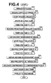
FIG. 4 is a flow chart for explaining operation of the mammographic imaging and display system employing one embodiment of the radiographic imaging apparatus of the invention, -
FIG. 5 is a timing chart showing ON/OFF state of an imaging switch, timing of application of radiation from a radiation source and timing of moving the radiation source during a series of operations of an imaging sequence, -
FIG. 6 is a flow chart for explaining operation of the mammographic imaging and display system employing one embodiment of the radiographic imaging apparatus of the invention when the imaging switch is accidentally turned into OFF state, and -
FIG. 7 is a diagram illustrating one example of a table that associates each of a plurality of operators with a threshold value of OFF period that is set in advance for the operator. - Hereinafter, a mammographic imaging and display system employing one embodiment of a radiographic imaging apparatus of the invention will be described with reference to the drawings.
FIG. 1 is a diagram illustrating the schematic configuration of the entire mammographic imaging and display system of this embodiment. - As shown in
FIG. 1 , the mammographic imaging anddisplay system 1 of this embodiment includes amammographic imaging apparatus 10, acomputer 2 connected to themammographic imaging apparatus 10, and amonitor 3, aninput unit 4 and animaging switch 5 connected to thecomputer 2. - As shown in
FIG. 1 , themammographic imaging apparatus 10 includes abase 11, arotation shaft 12 that is rotatable and is movable in the vertical direction (Z-direction) relative to thebase 11, and anarm 13 that is connected to thebase 11 via therotation shaft 12.FIG. 2 shows thearm 13 viewed from the right side ofFIG. 1 . - The
arm 13 is C-shaped, and provided with an imaging table 14, where a breast is placed, at one end thereof and aradiation source unit 16 at the other end thereof such that theradiation source unit 16 faces the imaging table 14. The movement of thearm 13 in the vertical direction is controlled by anarm controller 31, which is built in thebase 11. - The imaging table 14 contains therein a
radiographic image detector 15, such as a flat panel detector, and adetector controller 33, which controls reading of electric charge signals from theradiographic image detector 15, etc. - The imaging table 14 also contains therein a circuit board, etc. The circuit board includes a charge amplifier for converting electric charge signals read out from the
radiographic image detector 15 into voltage signals, a correlated double sampling circuit for sampling the voltage signals outputted from the charge amplifier, an AD converter for converting the voltage signals into digital signals, etc. - The
radiographic image detector 15 is of a type that is repeatedly usable to record and read a radiographic image. Theradiation detector 15 may be a so-called direct-type radiographic image detector, which directly receives the radiation and generates electric charges, or may be a so-called indirect-type radiographic image detector, which once converts the radiation into visible light, and then converts the visible light into electric charge signals. As the reading system to read out the radiographic image signal, a so-called TFT reading system that reads out the radiographic image signal with turning on and off TFT (thin film transistor) switches, or a so-called optical reading system that reads out the radiographic image signal by applying reading light may be used; however, this is not intended to limit the invention, and any other system may be used. - The
radiation source unit 16 contains therein aradiation source 17 and aradiation source controller 32. Theradiation source 17 includes an X-ray tube. The X-ray tube includes a capacitor, which is used when a high tube voltage is applied, and an anode, which emits radiation when being hit by electron beams while being rotated. Theradiation source controller 32 controls a start-up operation and a shut-down operation of the X-ray tube of theradiation source 17, timing of application of radiation from theradiation source 17, radiation generation conditions (such as tube current, time, tube voltage, etc.) at theradiation source 17, etc. - Further, at the middle portion of the
arm 13, acompression paddle 18 disposed above the imaging table 14 for holding and compressing the breast, asupport 20 for supporting thecompression paddle 18, and amoving mechanism 19 for moving thesupport 20 in the vertical direction are disposed. The position and the compressing pressure of thecompression paddle 18 are controlled by acompression paddle controller 34. - The
computer 2 includes a central processing unit (CPU), a storage device, such as a semiconductor memory, a hard disk, a SSD, etc., and these hardware devices form animaging control unit 40, a radiographicimage storage unit 41 and adisplay control unit 42, as shown inFIG. 3 . - The
imaging control unit 40 outputs predetermined control signals to thecontrollers 31 to 34 to control the imaging sequence of the entire system. A specific control method will be described in detail later. - The radiographic
image storage unit 41 stores two radiographic image signals detected by theradiographic image detector 15 in imaging operations from two different imaging directions. - The
display control unit 42 applies predetermined signal processing to the radiographic image signals read out from the radiographicimage storage unit 41 and then displays a stereo image of the breast on themonitor 3. - The
input unit 4 is formed by a pointing device, such as a keyboard and a mouse, and receives an input by the operator, such as an input of imaging conditions. - The
imaging switch 5 is a button used to instruct to perform a series of operations of an imaging sequence including the imaging operations from two different imaging directions. While theimaging switch 5 is pressed by the operator and is in ON state, theimaging control unit 40 of thecomputer 2 controls the individual units so that the series of operations of the imaging sequence are performed. In a case where theimaging switch 5 is turned into OFF state due to the operator accidentally releasing theimaging switch 5 or due to chattering or electrical noise, for example, theimaging control unit 40 stops or continues part of the operations in the imaging sequence depending on the length of period of the OFF state. How the part of operations in the imaging sequence is controlled will be described in detail later. - The
monitor 3 is configured to be capable of displaying a stereo image using two radiographic image signals outputted from thecomputer 2. As an example of an arrangement for displaying a stereo image, an arrangement where two radiographic images based on two radiographic image signals are displayed using two screens, and one of the radiographic images is directed to the right eye of the observer and the other of the radiographic images is directed to the left eye of the observer by using a half mirror or a polarizing glass to achieve display of a stereo image may be employed. Alternatively, for example, an arrangement where two radiographic images are displayed with being superimposed one another and offset from one another by a distance corresponding to a predetermined parallax and the displayed image is observed through polarizing glasses to achieve generation of a stereo image, or an arrangement where two radiographic images are displayed on a 3D liquid crystal display that allows stereoscopic viewing, such as a display of the parallax barrier system or the lenticular system, to achieve generation of a stereo image may be employed. - Next, operation of the mammographic imaging and display system of this embodiment is described with reference to the flow chart shown in
FIG. 4 and the timing chart shown inFIG. 5. FIG. 5 shows ON/OFF state of theimaging switch 5, timing of application of radiation from theradiation source 17, and timing of moving the radiation source 17 (operation timing of a driving motor for moving the radiation source 17) during a series of operations of an imaging sequence. First, a series of operations of the imaging sequence in a case where theimaging switch 5 is not turned into the above-described OFF state during the imaging sequence are described. - First, after power supplies to the
mammographic imaging apparatus 10, thecomputer 2 and themonitor 3 are turned on, the breast of a subject M is placed on the imaging table 14 and the breast is compressed by thecompression paddle 18 with a predetermined pressure (S10). - Then, when the operator presses the
imaging switch 5, theimaging switch 5 is turned into ON state, as shown inFIG. 5 (S12), and the imaging sequence is started by the imaging control unit 40 (S14). Specifically, first, a control signal is outputted from theimaging control unit 40 to theradiation source controller 32. In response to the inputted control signal, theradiation source controller 32 starts the start-up operation of the X-ray tube of the radiation source 17 (S16). The start-up operation of the X-ray tube may include, for example, starting rotation of the anode, charging the capacitor, etc. - After the start-up operation of the X-ray tube of the
radiation source 17 is finished, theimaging control unit 40 performs an imaging operation to take a first radiographic image among two radiographic images forming a stereo image. - Specifically, first, the
imaging control unit 40 reads out imaging angles θ set in advance for taking a stereo image, and outputs information of the read-out imaging angles θ to thearm controller 31. In this embodiment, it is assumed that θ=θ° and θ=4° are stored in advance as the information of the imaging angles θ; however, this is not intended to limit the invention, and any imaging angles can be set by operator via theinput unit 4. - The
arm controller 31 receives the information of the imaging angles, θ=0° and θ=4°, outputted from theimaging control unit 40. Then, in response to the control signal outputted from theimaging control unit 40, thearm controller 31 outputs, first, a control signal for moving thearm 13 to be perpendicular to the imaging table 14, as shown inFIG. 2 , based on the information of θ=0°. - In the state where the
arm 13 has been moved to be perpendicular to the imaging table 14 in response to the control signal outputted from thearm controller 31, theimaging control unit 40 outputs a control signal to theradiation source controller 32 and thedetector controller 33 to apply radiation and read out a radiographic image signal. - In response to the inputted control signal, the
radiation source controller 32 starts application of the tube voltage (V = V1) at theradiation source 17, thereby starting the first application of radiation shown inFIG. 5 (S18). - Then, a radiographic image of the breast taken from the direction of 0° by the first application of radiation from the
radiation source 17 is detected by the radiographic image detector 15 (S20). - When a radiation application period of one shot, which is set in advance as shown in
FIG. 5 , has elapsed, theradiation source controller 32 sets the tube voltage at theradiation source 17 to be V = V0, thereby ending the first application of radiation (S22). It should be noted that V0 is a tube voltage at which emission of the radiation from theradiation source 17 is stopped, and may be a certain voltage around 5V or may be 0V. - Then, the
detector controller 33 reads out a radiographic image signal from theradiographic image detector 15 and applies predetermined signal processing to the radiographic image signal. The radiographic image signal subjected to the signal processing is stored in the radiographicimage storage unit 41 of the computer 2 (S24). - After the first radiographic image has been taken, as described above, operation to move the
radiation source unit 17, as shown inFIG. 5 , is started (S26). - Specifically, in response to the control signal outputted from the
imaging control unit 40, thearm controller 31 outputs a control signal for rotating thearm 13 by an angle of +θ° relative to the direction perpendicular to the imaging table 14, as shown inFIG. 2 . Namely, in this embodiment, a control signal for rotating thearm 13 by an angle of 4° relative to the direction perpendicular to the imaging table 14 is outputted. - Based on the control signal outputted from the
arm controller 31, thearm 13 is moved in the direction of 4°, and theradiation source unit 16 is also moved in the direction of 4°. - In the state where the
arm 13 has been rotated by 4° in response to the control signal outputted from thearm controller 31, theimaging control unit 40 outputs a control signal to theradiation source controller 32 and thedetector controller 33 to apply radiation and read out a radiographic image signal. - In response to the inputted control signal, the
radiation source controller 32 starts application of the tube voltage (V = V1) at theradiation source 17, thereby starting the second application of radiation shown inFIG. 5 (S28). - Then, a radiographic image of the breast taken from the direction of 4° by the second application of radiation from the
radiation source 17 is detected by the radiographic image detector 15 (S30). - When the radiation application period of one shot, which is set in advance as shown in
FIG. 5 , has elapsed, theradiation source controller 32 sets the tube voltage at theradiation source 17 to be V = V0, thereby ending the second application of radiation (S32) . - Then, the
detector controller 33 reads out a radiographic image signal from theradiographic image detector 15 and applies predetermined signal processing to the radiographic image signal. The radiographic image signal subjected to the signal processing is stored in the radiographicimage storage unit 41 of the computer 2 (S34). - When the imaging operations to take the two radiographic images forming a stereo image, as described above, are finished, the operator releases the
imaging switch 5, thereby turning theimaging switch 5 into OFF state. When the imaging operations have been finished and theimaging switch 5 has been turned into OFF state, theimaging control unit 40 ends the imaging sequence and outputs a control signal to thecompression paddle controller 34. In response to the inputted control signal, thecompression paddle controller 34 releases the compression of the breast by the compression paddle 18 (S38). - Further, the
imaging control unit 40 outputs a control signal to theradiation source controller 32. In response to the inputted control signal, theradiation source controller 32 performs the shut-down operation of the X-ray tube of theradiation source 17 of the radiation source unit 16 (S40). The shut-down operation of the X-ray tube herein may include, for example, stopping the rotation of the anode, stopping the charging of the capacitor, etc. - Then, the two radiographic image signals stored in the radiographic
image storage unit 41, as described above, are read out by thedisplay control unit 42. Thedisplay control unit 42 applies predetermined processing to these radiographic image signals, and the processed radiographic image signals are outputted to themonitor 3. Then, a radiographic image for the right eye and a radiographic image for the left eye are displayed on themonitor 3, thereby achieving display of the stereo image of the breast (S42). - The series of operations in a normal imaging sequence have been described. Next, operations in a case where the
imaging switch 5 is accidentally turned into OFF state during a period from a point of time at which theimaging switch 5 is pressed by the operator to a point of time at which the operator releases theimaging switch 5 after two radiographic images are taken is described with reference to the flow chart shown inFIG. 6 . - When the
imaging switch 5 is accidentally turned into OFF state after a point of time at which theimaging switch 5 is pressed by the operator (S50: YES) due to the operator accidentally releasing theimaging switch 5 or due to chattering or electrical noise, for example, then, if radiation is being applied from theradiation source 17 at that time, that is, if it is during the first application of radiation (where the tube voltage V = V1) or the second application of radiation (where the tube voltage V = V1) shown inFIG. 5 (S52 : YES), theimaging control unit 40 outputs a control signal to theradiation source controller 32, and theradiation source controller 32 stops the application of radiation (S54). Further, at this time, if theradiation source 17 is being moved (S56: YES), theimaging control unit 40 outputs a control signal to thearm controller 31, and thearm controller 31 stops the movement of the arm 13 (the radiation source unit 16) (S58). - The
imaging control unit 40 measures a time elapsed from the point of time at which theimaging switch 5 is turned into OFF state (S60). If the period of the OFF state (OFF period) is not more than a predetermined threshold value (S62: YES), operations in the imaging sequence other than the application of radiation and the movement of theradiation source 17 described above are continuously performed (S64). Specifically, for example, the compression of the breast by thecompression paddle 18, the start-up state of the X-ray tube of theradiation source 17, etc., are maintained. - Then, when the
imaging switch 5 is turned into ON state while the OFF period is still not more than the predetermined threshold value because theimaging switch 5 is pressed by the operator again or the influence of chattering or electrical noise has disappeared (S66), theimaging control unit 40 restarts the movement of theradiation source 17 and continuously performs the normal imaging sequence (S68). - In contrast, if the OFF period of the
imaging switch 5 has exceeded the predetermined threshold value (S62: NO), theimaging control unit 40 outputs a control signal to thecompression paddle controller 34. In response to the inputted control signal, thecompression paddle controller 34 releases the compression of the breast by the compression paddle 18 (S70). Further, theimaging control unit 40 outputs a control signal to theradiation source controller 32. In response to the inputted control signal, theradiation source controller 32 performs the shut-down operation of the X-ray tube of the radiation source 17 (S72). Then, theimaging control unit 40 stops the imaging sequence (S74). - According to the mammographic imaging and display system of the above-described embodiment, when the imaging switch it turned into OFF state only for a given period, if the OFF period is not more than a predetermined threshold value, the compression by the compression paddle, the start-up operation of the X-ray tube, etc., are continuously performed without being stopped. Therefore, the operation can immediately be returned to the normal imaging sequence, thereby allowing taking an appropriate stereo image.
- Although only the compression of the breast and the start-up operation of the X-ray tube, among the series of operations of the imaging sequence, are continuously performed when the OFF period of the
imaging switch 5 is not more than a predetermined threshold value in the above-described embodiment, this is not intended to limit the invention, and any other operation may also be continued. - That is, the reason of continuing the compression of the breast is that, once the compression of the breast is released, the shape of the breast changes when the breast is compressed again and it is impossible to take an appropriate stereo image. Therefore, any other operation that is undesirable to be stopped in view of taking an appropriate stereo image may also be continued.
- Further, the reason of not stopping the start-up operation of the X-ray tube is that, once the X-ray tube is shut down, it takes time to start up the X-ray tube again. Therefore, any other operation that is undesirable to be stopped in view of the time taken for returning to the normal operation may also be continued.
- Still further, although the movement of the
radiation source unit 16 is stopped when theimaging switch 5 is turned into OFF state in the above-described embodiment, this operation is set in view of safety and is not intended to limit the invention. In a case where higher priority is set on reduction of the imaging time than on safety, for example, the movement of theradiation source unit 16 may be continued when theimaging switch 5 is turned into OFF state and the OFF period is not more than a predetermined threshold value. - It is desirable that the threshold value of the OFF period used in the above-described embodiment is set to be not smaller than one second and not greater than two seconds, for example.
- Further, the threshold value of the OFF period may be set in advance or may arbitrarily be set by the operator via the
input unit 4. Still further, a plurality of threshold values may be set in advance for the OFF period, and the operator may select one of the threshold values via theinput unit 4 so that the selected threshold value is set. - Yet further, as shown in
FIG. 6 , threshold values (TA, TB, TC, ...) of the OFF period for different operators (A, B, C, ...) may be set in advance as a table, and information of operator may be received via theinput unit 4 so that the threshold value of the OFF period correspond to the received information of operator is set. - Further, although the radiographic imaging apparatus of the invention is applied to an imaging apparatus that takes a stereo image of the breast in the above-described embodiment, this is not intended to limit the invention. The radiographic imaging apparatus of the invention is applicable to any other apparatus that takes a plurality of radiographic image from different imaging directions by moving the radiation source, such as a tomosynthesis imaging apparatus.
Claims (11)
- A radiographic imaging apparatus including a radiation exposure unit for applying radiation emitted from a radiation source to a subject from different imaging directions, and a radiographic image detector for detecting a radiographic image for each imaging direction generated by the application of radiation by the radiation exposure unit, characterized in that the apparatus comprises
an imaging control unit for exerting control such that a series of operations of an imaging sequence including the application of radiation from each imaging direction are continuously performed when an imaging switch is continuously in ON state,
wherein if the imaging switch is turned into OFF state only for a given period and the given period is not more than a predetermined threshold value, the imaging control unit continuously performs part of the operations of the imaging sequence. - The radiographic imaging apparatus as claimed in claim 1, wherein the subject is a breast and the apparatus comprises a compression paddle for compressing the breast, and
wherein, if the period of the OFF state is not more than the threshold value, the imaging control unit continues compression by the compression paddle as the part of the operations of the imaging sequence, or if the period of the OFF state is longer than the threshold value, the imaging control unit releases the compression by the compression paddle. - The radiographic imaging apparatus as claimed in claim 1 or 2, wherein the radiation source comprises an X-ray tube, and
wherein, if the period of the OFF state is not more than the threshold value, the imaging control unit continues a start-up operation of the X-ray tube as the part of the operations of the imaging sequence, or if the period of the OFF state is longer than the threshold value, the imaging control unit exerts control to perform a shut-down operation of the X-ray tube. - The radiographic imaging apparatus as claimed in any one of claims 1 to 3, wherein, if the period of the OFF state of the imaging switch is not more than the threshold value, the imaging control unit stops the application of radiation.
- The radiographic imaging apparatus as claimed in any one of claims 1 to 4, wherein, if the period of the OFF state of the imaging switch is not more than the threshold value, the imaging control unit stops movement of the radiation source.
- The radiographic imaging apparatus as claimed in any one of claims 1 to 5, wherein the threshold value is not smaller than one second and not greater than two seconds.
- The radiographic imaging apparatus as claimed in any one of claims 1 to 6, comprising a threshold value setting reception unit for receiving an arbitrary value set as the threshold value.
- The radiographic imaging apparatus as claimed in any one of claims 1 to 7, wherein a plurality of values are set in advance for the threshold value.
- The radiographic imaging apparatus as claimed in claim 8, wherein a plurality of values for different operators are set in advance for the threshold value.
- The radiographic imaging apparatus as claimed in claim 9, wherein the imaging control unit receives information of the operator and sets the threshold value corresponding to the received operator.
- A radiographic imaging method including applying radiation emitted from a radiation source to a subject from different imaging directions, and detecting a radiographic image for each imaging direction generated by the application of radiation, characterized in that the method comprises
continuously performing a series of operations of an imaging sequence including the application of radiation from each imaging direction when an imaging switch is continuously in ON state, wherein, if the imaging switch is turned into OFF state only for a given period and the given period is not more than a predetermined threshold value, part of the operations of the imaging sequence is continuously performed.
Applications Claiming Priority (2)
| Application Number | Priority Date | Filing Date | Title |
|---|---|---|---|
| JP2011047808A JP5600305B2 (en) | 2011-03-04 | 2011-03-04 | Radiographic imaging method and apparatus |
| PCT/JP2012/001403 WO2012120841A1 (en) | 2011-03-04 | 2012-03-01 | Radiological imaging method and device |
Publications (3)
| Publication Number | Publication Date |
|---|---|
| EP2682058A1 true EP2682058A1 (en) | 2014-01-08 |
| EP2682058A4 EP2682058A4 (en) | 2014-08-13 |
| EP2682058B1 EP2682058B1 (en) | 2015-09-30 |
Family
ID=46797814
Family Applications (1)
| Application Number | Title | Priority Date | Filing Date |
|---|---|---|---|
| EP12755197.6A Active EP2682058B1 (en) | 2011-03-04 | 2012-03-01 | Radiological imaging method and device |
Country Status (5)
| Country | Link |
|---|---|
| US (2) | US9226724B2 (en) |
| EP (1) | EP2682058B1 (en) |
| JP (1) | JP5600305B2 (en) |
| CN (1) | CN103402432B (en) |
| WO (1) | WO2012120841A1 (en) |
Families Citing this family (7)
| Publication number | Priority date | Publication date | Assignee | Title |
|---|---|---|---|---|
| JP5600305B2 (en) * | 2011-03-04 | 2014-10-01 | 富士フイルム株式会社 | Radiographic imaging method and apparatus |
| WO2014126217A1 (en) * | 2013-02-14 | 2014-08-21 | 株式会社 東芝 | X-ray diagnostic device |
| CN105228526B (en) * | 2013-03-29 | 2018-06-08 | 通用电气公司 | Mammography apparatus |
| US10830712B2 (en) * | 2017-03-27 | 2020-11-10 | KUB Technologies, Inc. | System and method for cabinet x-ray systems with camera |
| CN107179650A (en) * | 2017-05-12 | 2017-09-19 | 太仓诚泽网络科技有限公司 | A kind of method for imaging based on ray |
| CN108919608B (en) * | 2018-06-27 | 2023-07-25 | 上海联影医疗科技股份有限公司 | Exposure process control method, device, equipment and medium |
| JP7208849B2 (en) * | 2019-03-28 | 2023-01-19 | 富士フイルム株式会社 | radiography system |
Family Cites Families (13)
| Publication number | Priority date | Publication date | Assignee | Title |
|---|---|---|---|---|
| JP2773357B2 (en) * | 1990-02-28 | 1998-07-09 | 株式会社島津製作所 | Angiography imaging device |
| JPH05237080A (en) * | 1992-02-28 | 1993-09-17 | Hitachi Medical Corp | X-ray apparatus |
| US5594772A (en) * | 1993-11-26 | 1997-01-14 | Kabushiki Kaisha Toshiba | Computer tomography apparatus |
| JPH118934A (en) * | 1997-06-17 | 1999-01-12 | Aloka Co Ltd | Medical device |
| JP4460695B2 (en) * | 1999-11-24 | 2010-05-12 | 株式会社東芝 | X-ray computed tomography system |
| JP3677199B2 (en) * | 2000-07-31 | 2005-07-27 | 和泉電気株式会社 | Push button switch and teaching pendant with the same |
| DE10347735B4 (en) * | 2003-10-14 | 2012-01-26 | Siemens Ag | Motorized X-ray device |
| JP4828883B2 (en) * | 2004-07-21 | 2011-11-30 | 株式会社東芝 | X-ray imaging equipment |
| US7177393B2 (en) | 2004-07-21 | 2007-02-13 | Kabushiki Kaisha Toshiba | X-ray imaging apparatus |
| JP2010131170A (en) | 2008-12-04 | 2010-06-17 | Fujifilm Corp | Tomography apparatus |
| JP5590820B2 (en) * | 2009-05-18 | 2014-09-17 | キヤノン株式会社 | Control device, control method and program |
| JP5155252B2 (en) * | 2009-06-04 | 2013-03-06 | 富士フイルム株式会社 | Mammography stereotaxic device |
| JP5600305B2 (en) * | 2011-03-04 | 2014-10-01 | 富士フイルム株式会社 | Radiographic imaging method and apparatus |
-
2011
- 2011-03-04 JP JP2011047808A patent/JP5600305B2/en active Active
-
2012
- 2012-03-01 EP EP12755197.6A patent/EP2682058B1/en active Active
- 2012-03-01 CN CN201280011759.9A patent/CN103402432B/en active Active
- 2012-03-01 WO PCT/JP2012/001403 patent/WO2012120841A1/en not_active Ceased
-
2013
- 2013-08-22 US US13/973,082 patent/US9226724B2/en active Active
-
2015
- 2015-11-25 US US14/951,845 patent/US9510801B2/en active Active
Also Published As
| Publication number | Publication date |
|---|---|
| CN103402432B (en) | 2016-08-17 |
| EP2682058B1 (en) | 2015-09-30 |
| JP5600305B2 (en) | 2014-10-01 |
| EP2682058A4 (en) | 2014-08-13 |
| WO2012120841A1 (en) | 2012-09-13 |
| CN103402432A (en) | 2013-11-20 |
| US9226724B2 (en) | 2016-01-05 |
| US20130336444A1 (en) | 2013-12-19 |
| US9510801B2 (en) | 2016-12-06 |
| JP2012183169A (en) | 2012-09-27 |
| US20160073996A1 (en) | 2016-03-17 |
Similar Documents
| Publication | Publication Date | Title |
|---|---|---|
| US9510801B2 (en) | Radiographic imaging method and apparatus | |
| JP5490038B2 (en) | Breast imaging device | |
| US20120051502A1 (en) | Mammography system | |
| US20120051501A1 (en) | Radiation image radiographing apparatus and radiation image radiographing and displaying method | |
| WO2012090472A1 (en) | Imaging control device and imaging control method | |
| US20120068079A1 (en) | Radiation imaging apparatus and stereoscopic image display method | |
| JP2012029759A (en) | Radiological image radiographing and displaying method and apparatus | |
| JP2012024519A (en) | Radiological image radiographing and displaying method and apparatus | |
| WO2012114757A1 (en) | Radiographic imaging method and device | |
| EP2692292A1 (en) | Radiological breast-image display method, radiological breast-image display device, and programme | |
| US20120025088A1 (en) | Radiological image radiographing and displaying method and apparatus | |
| JP2011212067A (en) | Radiological image taking and displaying method and system | |
| JP2012068610A (en) | Stereoscopic vision image display device, radiation image photographing and display system and stereoscopic vision image display method | |
| WO2012029705A1 (en) | Device and method for delivering images | |
| WO2012056679A1 (en) | 3d image display system and 3d image display device | |
| WO2012039121A1 (en) | Radiation image capturing device and radiation image capturing method | |
| JP2012253757A (en) | Stereoscopic image display device and operation method therefor | |
| US20120051503A1 (en) | Stereoscopic image displaying method and apparatus | |
| WO2012105188A1 (en) | Stereoscopic image display device and method, and program | |
| JP2012176037A (en) | Stereoscopic radiological image generating device, method, and program | |
| WO2012039126A1 (en) | Radiation image capturing device, image data compression device and image data compression method | |
| WO2013024572A1 (en) | Image reproduction device, image reproduction method, and program | |
| JP2012247685A (en) | Method and device for displaying stereographic image | |
| JP2013039365A (en) | Radiographic apparatus and operation method of the same | |
| JP2013123553A (en) | Radiation imaging apparatus |
Legal Events
| Date | Code | Title | Description |
|---|---|---|---|
| PUAI | Public reference made under article 153(3) epc to a published international application that has entered the european phase |
Free format text: ORIGINAL CODE: 0009012 |
|
| 17P | Request for examination filed |
Effective date: 20130906 |
|
| AK | Designated contracting states |
Kind code of ref document: A1 Designated state(s): AL AT BE BG CH CY CZ DE DK EE ES FI FR GB GR HR HU IE IS IT LI LT LU LV MC MK MT NL NO PL PT RO RS SE SI SK SM TR |
|
| DAX | Request for extension of the european patent (deleted) | ||
| A4 | Supplementary search report drawn up and despatched |
Effective date: 20140715 |
|
| RIC1 | Information provided on ipc code assigned before grant |
Ipc: A61B 6/10 20060101ALI20140709BHEP Ipc: H01H 3/02 20060101ALN20140709BHEP Ipc: A61B 6/00 20060101AFI20140709BHEP Ipc: A61B 6/04 20060101ALI20140709BHEP |
|
| RIC1 | Information provided on ipc code assigned before grant |
Ipc: H01H 3/02 20060101ALN20150323BHEP Ipc: A61B 6/00 20060101AFI20150323BHEP Ipc: A61B 6/10 20060101ALI20150323BHEP Ipc: A61B 6/04 20060101ALI20150323BHEP |
|
| GRAP | Despatch of communication of intention to grant a patent |
Free format text: ORIGINAL CODE: EPIDOSNIGR1 |
|
| RIC1 | Information provided on ipc code assigned before grant |
Ipc: H01H 3/02 20060101ALN20150413BHEP Ipc: A61B 6/04 20060101ALI20150413BHEP Ipc: A61B 6/00 20060101AFI20150413BHEP Ipc: A61B 6/10 20060101ALI20150413BHEP |
|
| INTG | Intention to grant announced |
Effective date: 20150508 |
|
| RAP1 | Party data changed (applicant data changed or rights of an application transferred) |
Owner name: FUJIFILM CORPORATION |
|
| GRAS | Grant fee paid |
Free format text: ORIGINAL CODE: EPIDOSNIGR3 |
|
| GRAA | (expected) grant |
Free format text: ORIGINAL CODE: 0009210 |
|
| AK | Designated contracting states |
Kind code of ref document: B1 Designated state(s): AL AT BE BG CH CY CZ DE DK EE ES FI FR GB GR HR HU IE IS IT LI LT LU LV MC MK MT NL NO PL PT RO RS SE SI SK SM TR |
|
| REG | Reference to a national code |
Ref country code: CH Ref legal event code: EP Ref country code: GB Ref legal event code: FG4D |
|
| REG | Reference to a national code |
Ref country code: AT Ref legal event code: REF Ref document number: 751893 Country of ref document: AT Kind code of ref document: T Effective date: 20151015 |
|
| REG | Reference to a national code |
Ref country code: IE Ref legal event code: FG4D |
|
| REG | Reference to a national code |
Ref country code: DE Ref legal event code: R096 Ref document number: 602012011167 Country of ref document: DE |
|
| PG25 | Lapsed in a contracting state [announced via postgrant information from national office to epo] |
Ref country code: LT Free format text: LAPSE BECAUSE OF FAILURE TO SUBMIT A TRANSLATION OF THE DESCRIPTION OR TO PAY THE FEE WITHIN THE PRESCRIBED TIME-LIMIT Effective date: 20150930 Ref country code: GR Free format text: LAPSE BECAUSE OF FAILURE TO SUBMIT A TRANSLATION OF THE DESCRIPTION OR TO PAY THE FEE WITHIN THE PRESCRIBED TIME-LIMIT Effective date: 20151231 Ref country code: LV Free format text: LAPSE BECAUSE OF FAILURE TO SUBMIT A TRANSLATION OF THE DESCRIPTION OR TO PAY THE FEE WITHIN THE PRESCRIBED TIME-LIMIT Effective date: 20150930 Ref country code: FI Free format text: LAPSE BECAUSE OF FAILURE TO SUBMIT A TRANSLATION OF THE DESCRIPTION OR TO PAY THE FEE WITHIN THE PRESCRIBED TIME-LIMIT Effective date: 20150930 Ref country code: NO Free format text: LAPSE BECAUSE OF FAILURE TO SUBMIT A TRANSLATION OF THE DESCRIPTION OR TO PAY THE FEE WITHIN THE PRESCRIBED TIME-LIMIT Effective date: 20151230 |
|
| REG | Reference to a national code |
Ref country code: NL Ref legal event code: MP Effective date: 20150930 |
|
| REG | Reference to a national code |
Ref country code: FR Ref legal event code: PLFP Year of fee payment: 5 |
|
| REG | Reference to a national code |
Ref country code: LT Ref legal event code: MG4D |
|
| REG | Reference to a national code |
Ref country code: AT Ref legal event code: MK05 Ref document number: 751893 Country of ref document: AT Kind code of ref document: T Effective date: 20150930 |
|
| PG25 | Lapsed in a contracting state [announced via postgrant information from national office to epo] |
Ref country code: SE Free format text: LAPSE BECAUSE OF FAILURE TO SUBMIT A TRANSLATION OF THE DESCRIPTION OR TO PAY THE FEE WITHIN THE PRESCRIBED TIME-LIMIT Effective date: 20150930 Ref country code: HR Free format text: LAPSE BECAUSE OF FAILURE TO SUBMIT A TRANSLATION OF THE DESCRIPTION OR TO PAY THE FEE WITHIN THE PRESCRIBED TIME-LIMIT Effective date: 20150930 Ref country code: RS Free format text: LAPSE BECAUSE OF FAILURE TO SUBMIT A TRANSLATION OF THE DESCRIPTION OR TO PAY THE FEE WITHIN THE PRESCRIBED TIME-LIMIT Effective date: 20150930 |
|
| PG25 | Lapsed in a contracting state [announced via postgrant information from national office to epo] |
Ref country code: NL Free format text: LAPSE BECAUSE OF FAILURE TO SUBMIT A TRANSLATION OF THE DESCRIPTION OR TO PAY THE FEE WITHIN THE PRESCRIBED TIME-LIMIT Effective date: 20150930 Ref country code: ES Free format text: LAPSE BECAUSE OF FAILURE TO SUBMIT A TRANSLATION OF THE DESCRIPTION OR TO PAY THE FEE WITHIN THE PRESCRIBED TIME-LIMIT Effective date: 20150930 Ref country code: SK Free format text: LAPSE BECAUSE OF FAILURE TO SUBMIT A TRANSLATION OF THE DESCRIPTION OR TO PAY THE FEE WITHIN THE PRESCRIBED TIME-LIMIT Effective date: 20150930 Ref country code: CZ Free format text: LAPSE BECAUSE OF FAILURE TO SUBMIT A TRANSLATION OF THE DESCRIPTION OR TO PAY THE FEE WITHIN THE PRESCRIBED TIME-LIMIT Effective date: 20150930 Ref country code: IS Free format text: LAPSE BECAUSE OF FAILURE TO SUBMIT A TRANSLATION OF THE DESCRIPTION OR TO PAY THE FEE WITHIN THE PRESCRIBED TIME-LIMIT Effective date: 20160130 Ref country code: EE Free format text: LAPSE BECAUSE OF FAILURE TO SUBMIT A TRANSLATION OF THE DESCRIPTION OR TO PAY THE FEE WITHIN THE PRESCRIBED TIME-LIMIT Effective date: 20150930 |
|
| PG25 | Lapsed in a contracting state [announced via postgrant information from national office to epo] |
Ref country code: PT Free format text: LAPSE BECAUSE OF FAILURE TO SUBMIT A TRANSLATION OF THE DESCRIPTION OR TO PAY THE FEE WITHIN THE PRESCRIBED TIME-LIMIT Effective date: 20160201 Ref country code: AT Free format text: LAPSE BECAUSE OF FAILURE TO SUBMIT A TRANSLATION OF THE DESCRIPTION OR TO PAY THE FEE WITHIN THE PRESCRIBED TIME-LIMIT Effective date: 20150930 Ref country code: RO Free format text: LAPSE BECAUSE OF FAILURE TO SUBMIT A TRANSLATION OF THE DESCRIPTION OR TO PAY THE FEE WITHIN THE PRESCRIBED TIME-LIMIT Effective date: 20150930 Ref country code: PL Free format text: LAPSE BECAUSE OF FAILURE TO SUBMIT A TRANSLATION OF THE DESCRIPTION OR TO PAY THE FEE WITHIN THE PRESCRIBED TIME-LIMIT Effective date: 20150930 |
|
| REG | Reference to a national code |
Ref country code: DE Ref legal event code: R097 Ref document number: 602012011167 Country of ref document: DE |
|
| PLBE | No opposition filed within time limit |
Free format text: ORIGINAL CODE: 0009261 |
|
| STAA | Information on the status of an ep patent application or granted ep patent |
Free format text: STATUS: NO OPPOSITION FILED WITHIN TIME LIMIT |
|
| PG25 | Lapsed in a contracting state [announced via postgrant information from national office to epo] |
Ref country code: BE Free format text: LAPSE BECAUSE OF NON-PAYMENT OF DUE FEES Effective date: 20160331 Ref country code: DK Free format text: LAPSE BECAUSE OF FAILURE TO SUBMIT A TRANSLATION OF THE DESCRIPTION OR TO PAY THE FEE WITHIN THE PRESCRIBED TIME-LIMIT Effective date: 20150930 |
|
| 26N | No opposition filed |
Effective date: 20160701 |
|
| PG25 | Lapsed in a contracting state [announced via postgrant information from national office to epo] |
Ref country code: LU Free format text: LAPSE BECAUSE OF FAILURE TO SUBMIT A TRANSLATION OF THE DESCRIPTION OR TO PAY THE FEE WITHIN THE PRESCRIBED TIME-LIMIT Effective date: 20160301 Ref country code: MC Free format text: LAPSE BECAUSE OF FAILURE TO SUBMIT A TRANSLATION OF THE DESCRIPTION OR TO PAY THE FEE WITHIN THE PRESCRIBED TIME-LIMIT Effective date: 20150930 |
|
| REG | Reference to a national code |
Ref country code: CH Ref legal event code: PL |
|
| PG25 | Lapsed in a contracting state [announced via postgrant information from national office to epo] |
Ref country code: SI Free format text: LAPSE BECAUSE OF FAILURE TO SUBMIT A TRANSLATION OF THE DESCRIPTION OR TO PAY THE FEE WITHIN THE PRESCRIBED TIME-LIMIT Effective date: 20150930 |
|
| REG | Reference to a national code |
Ref country code: IE Ref legal event code: MM4A |
|
| PG25 | Lapsed in a contracting state [announced via postgrant information from national office to epo] |
Ref country code: BE Free format text: LAPSE BECAUSE OF FAILURE TO SUBMIT A TRANSLATION OF THE DESCRIPTION OR TO PAY THE FEE WITHIN THE PRESCRIBED TIME-LIMIT Effective date: 20150930 |
|
| PG25 | Lapsed in a contracting state [announced via postgrant information from national office to epo] |
Ref country code: IE Free format text: LAPSE BECAUSE OF NON-PAYMENT OF DUE FEES Effective date: 20160301 Ref country code: CH Free format text: LAPSE BECAUSE OF NON-PAYMENT OF DUE FEES Effective date: 20160331 Ref country code: LI Free format text: LAPSE BECAUSE OF NON-PAYMENT OF DUE FEES Effective date: 20160331 |
|
| REG | Reference to a national code |
Ref country code: FR Ref legal event code: PLFP Year of fee payment: 6 |
|
| PG25 | Lapsed in a contracting state [announced via postgrant information from national office to epo] |
Ref country code: MT Free format text: LAPSE BECAUSE OF FAILURE TO SUBMIT A TRANSLATION OF THE DESCRIPTION OR TO PAY THE FEE WITHIN THE PRESCRIBED TIME-LIMIT Effective date: 20150930 |
|
| REG | Reference to a national code |
Ref country code: FR Ref legal event code: PLFP Year of fee payment: 7 |
|
| PG25 | Lapsed in a contracting state [announced via postgrant information from national office to epo] |
Ref country code: HU Free format text: LAPSE BECAUSE OF FAILURE TO SUBMIT A TRANSLATION OF THE DESCRIPTION OR TO PAY THE FEE WITHIN THE PRESCRIBED TIME-LIMIT; INVALID AB INITIO Effective date: 20120301 Ref country code: CY Free format text: LAPSE BECAUSE OF FAILURE TO SUBMIT A TRANSLATION OF THE DESCRIPTION OR TO PAY THE FEE WITHIN THE PRESCRIBED TIME-LIMIT Effective date: 20150930 Ref country code: SM Free format text: LAPSE BECAUSE OF FAILURE TO SUBMIT A TRANSLATION OF THE DESCRIPTION OR TO PAY THE FEE WITHIN THE PRESCRIBED TIME-LIMIT Effective date: 20150930 |
|
| PG25 | Lapsed in a contracting state [announced via postgrant information from national office to epo] |
Ref country code: MT Free format text: LAPSE BECAUSE OF FAILURE TO SUBMIT A TRANSLATION OF THE DESCRIPTION OR TO PAY THE FEE WITHIN THE PRESCRIBED TIME-LIMIT Effective date: 20160331 Ref country code: MK Free format text: LAPSE BECAUSE OF FAILURE TO SUBMIT A TRANSLATION OF THE DESCRIPTION OR TO PAY THE FEE WITHIN THE PRESCRIBED TIME-LIMIT Effective date: 20150930 Ref country code: TR Free format text: LAPSE BECAUSE OF FAILURE TO SUBMIT A TRANSLATION OF THE DESCRIPTION OR TO PAY THE FEE WITHIN THE PRESCRIBED TIME-LIMIT Effective date: 20150930 |
|
| PG25 | Lapsed in a contracting state [announced via postgrant information from national office to epo] |
Ref country code: BG Free format text: LAPSE BECAUSE OF FAILURE TO SUBMIT A TRANSLATION OF THE DESCRIPTION OR TO PAY THE FEE WITHIN THE PRESCRIBED TIME-LIMIT Effective date: 20150930 |
|
| PG25 | Lapsed in a contracting state [announced via postgrant information from national office to epo] |
Ref country code: AL Free format text: LAPSE BECAUSE OF FAILURE TO SUBMIT A TRANSLATION OF THE DESCRIPTION OR TO PAY THE FEE WITHIN THE PRESCRIBED TIME-LIMIT Effective date: 20150930 |
|
| PGFP | Annual fee paid to national office [announced via postgrant information from national office to epo] |
Ref country code: GB Payment date: 20200219 Year of fee payment: 9 Ref country code: IT Payment date: 20200221 Year of fee payment: 9 |
|
| GBPC | Gb: european patent ceased through non-payment of renewal fee |
Effective date: 20210301 |
|
| PG25 | Lapsed in a contracting state [announced via postgrant information from national office to epo] |
Ref country code: GB Free format text: LAPSE BECAUSE OF NON-PAYMENT OF DUE FEES Effective date: 20210301 |
|
| PG25 | Lapsed in a contracting state [announced via postgrant information from national office to epo] |
Ref country code: IT Free format text: LAPSE BECAUSE OF NON-PAYMENT OF DUE FEES Effective date: 20210301 |
|
| P01 | Opt-out of the competence of the unified patent court (upc) registered |
Effective date: 20230515 |
|
| PGFP | Annual fee paid to national office [announced via postgrant information from national office to epo] |
Ref country code: DE Payment date: 20260128 Year of fee payment: 15 |
|
| PGFP | Annual fee paid to national office [announced via postgrant information from national office to epo] |
Ref country code: FR Payment date: 20260209 Year of fee payment: 15 |