EP2681567B1 - Sampling probes - Google Patents
Sampling probes Download PDFInfo
- Publication number
- EP2681567B1 EP2681567B1 EP12713814.7A EP12713814A EP2681567B1 EP 2681567 B1 EP2681567 B1 EP 2681567B1 EP 12713814 A EP12713814 A EP 12713814A EP 2681567 B1 EP2681567 B1 EP 2681567B1
- Authority
- EP
- European Patent Office
- Prior art keywords
- probe
- sample
- sampling probe
- plate
- magnets
- Prior art date
- Legal status (The legal status is an assumption and is not a legal conclusion. Google has not performed a legal analysis and makes no representation as to the accuracy of the status listed.)
- Active
Links
- 239000000523 sample Substances 0.000 title claims description 238
- 238000005070 sampling Methods 0.000 title claims description 63
- 230000005355 Hall effect Effects 0.000 claims description 25
- 229910052761 rare earth metal Inorganic materials 0.000 claims description 8
- 150000002910 rare earth metals Chemical class 0.000 claims description 8
- 230000003287 optical effect Effects 0.000 claims description 5
- 229910052751 metal Inorganic materials 0.000 claims description 4
- 239000002184 metal Substances 0.000 claims description 4
- 239000012530 fluid Substances 0.000 description 23
- 238000004891 communication Methods 0.000 description 14
- 230000007246 mechanism Effects 0.000 description 14
- 238000000034 method Methods 0.000 description 10
- 238000004163 cytometry Methods 0.000 description 7
- 238000006073 displacement reaction Methods 0.000 description 6
- 238000001514 detection method Methods 0.000 description 5
- 238000000684 flow cytometry Methods 0.000 description 4
- 230000005484 gravity Effects 0.000 description 4
- 239000000463 material Substances 0.000 description 4
- 238000011160 research Methods 0.000 description 4
- 238000012546 transfer Methods 0.000 description 4
- 230000001965 increasing effect Effects 0.000 description 3
- 238000007373 indentation Methods 0.000 description 3
- 238000012545 processing Methods 0.000 description 3
- CWYNVVGOOAEACU-UHFFFAOYSA-N Fe2+ Chemical compound [Fe+2] CWYNVVGOOAEACU-UHFFFAOYSA-N 0.000 description 2
- 229910052782 aluminium Inorganic materials 0.000 description 2
- XAGFODPZIPBFFR-UHFFFAOYSA-N aluminium Chemical compound [Al] XAGFODPZIPBFFR-UHFFFAOYSA-N 0.000 description 2
- 238000004458 analytical method Methods 0.000 description 2
- 230000008901 benefit Effects 0.000 description 2
- 230000008859 change Effects 0.000 description 2
- 230000000994 depressogenic effect Effects 0.000 description 2
- 238000010586 diagram Methods 0.000 description 2
- 238000013394 immunophenotyping Methods 0.000 description 2
- 230000002452 interceptive effect Effects 0.000 description 2
- 230000000284 resting effect Effects 0.000 description 2
- 230000004663 cell proliferation Effects 0.000 description 1
- 238000005260 corrosion Methods 0.000 description 1
- 230000007797 corrosion Effects 0.000 description 1
- 238000013461 design Methods 0.000 description 1
- 238000007876 drug discovery Methods 0.000 description 1
- 102000034287 fluorescent proteins Human genes 0.000 description 1
- 108091006047 fluorescent proteins Proteins 0.000 description 1
- 230000006870 function Effects 0.000 description 1
- 230000002068 genetic effect Effects 0.000 description 1
- 230000001939 inductive effect Effects 0.000 description 1
- 230000003834 intracellular effect Effects 0.000 description 1
- 238000004519 manufacturing process Methods 0.000 description 1
- 238000005259 measurement Methods 0.000 description 1
- 238000012544 monitoring process Methods 0.000 description 1
- 230000000737 periodic effect Effects 0.000 description 1
- 230000008569 process Effects 0.000 description 1
- 238000007789 sealing Methods 0.000 description 1
- 230000035945 sensitivity Effects 0.000 description 1
- 238000012163 sequencing technique Methods 0.000 description 1
- 239000000758 substrate Substances 0.000 description 1
Images


Classifications
-
- G—PHYSICS
- G01—MEASURING; TESTING
- G01N—INVESTIGATING OR ANALYSING MATERIALS BY DETERMINING THEIR CHEMICAL OR PHYSICAL PROPERTIES
- G01N35/00—Automatic analysis not limited to methods or materials provided for in any single one of groups G01N1/00 - G01N33/00; Handling materials therefor
- G01N35/10—Devices for transferring samples or any liquids to, in, or from, the analysis apparatus, e.g. suction devices, injection devices
- G01N35/1009—Characterised by arrangements for controlling the aspiration or dispense of liquids
- G01N35/1011—Control of the position or alignment of the transfer device
-
- G—PHYSICS
- G01—MEASURING; TESTING
- G01N—INVESTIGATING OR ANALYSING MATERIALS BY DETERMINING THEIR CHEMICAL OR PHYSICAL PROPERTIES
- G01N15/00—Investigating characteristics of particles; Investigating permeability, pore-volume, or surface-area of porous materials
- G01N15/10—Investigating individual particles
- G01N15/14—Electro-optical investigation, e.g. flow cytometers
- G01N15/1404—Fluid conditioning in flow cytometers, e.g. flow cells; Supply; Control of flow
-
- G—PHYSICS
- G01—MEASURING; TESTING
- G01N—INVESTIGATING OR ANALYSING MATERIALS BY DETERMINING THEIR CHEMICAL OR PHYSICAL PROPERTIES
- G01N35/00—Automatic analysis not limited to methods or materials provided for in any single one of groups G01N1/00 - G01N33/00; Handling materials therefor
- G01N35/0099—Automatic analysis not limited to methods or materials provided for in any single one of groups G01N1/00 - G01N33/00; Handling materials therefor comprising robots or similar manipulators
Definitions
- the present application generally relates to sampling probes, systems, apparatuses, and methods for hi-throughput flow cytometry and/or for processing samples in batches.
- sample probes required separate manipulation and handling of each sample, even when processing multiple samples.
- extended sample drawing probes often increased the risk of damage to such probes.
- WO2008/034914 A2 discloses a prior art dispenser device with an impact force adjustment mechanism for adjusting the force with which a spotting capillary hits a substrate surface. Two repulsing magnets act as a damper. Furthermore, a distance or position measurement for motion control is performed by counting the passage of optical or magnetic markers of the dispensing device.
- a sample probe with a built-in obstacle detection mechanism may reduce costs and increase time savings by reducing both instrument downtime and increasing probe position accuracy and durability.
- a compliant sample probe with position feedback that minimizes damage to the probe in cases of collisions and calibrates the location of the probe in three-dimensional space.
- a magnet-based probe with opposing magnets that provide force to push the probe back to a normal state after it has been depressed in contact with another object, and a Hall effect sensor that detects a change in magnetic field when the magnets are pushed closer to each other as the probe is depressed from its relaxed position.
- a restorative spring may include a single magnet, three magnets, or a metal spring, for example. It should be recognized that the restorative spring according to various embodiments described herein may be any object or assembly that can provide sufficient restorative force to return the probe to a relaxed position.
- a sampling system may include: a housing; a Hall effect sensor mounted onto the housing; and a sampling probe inserted into the housing, the sampling probe including an elongated portion and a plurality of magnets inserted onto the elongated portion.
- a plate sampling apparatus may include: a sampling compartment including a tray configured to receive a sample plate configured to include a plurality of samples; and a probe configured to obtain a sample from the sample plate, the probe including a fitting, an elongated portion extending from the fitting, and a restorative spring including a plurality of magnets inserted onto the elongated portion.
- a hi-throughput cytometry system including: a flow cytometer configured to acoustically focus a sample in a flowing fluid; and a plate sampler in fluidic communication with the flow cytometer, the plate sampler including: a sampling compartment including a tray configured to receive a sample plate configured to include a plurality of samples, and a probe configured to obtain a sample from the sample plate, the probe including a fitting, an elongated portion extending from the fitting, and a restorative spring including a plurality of magnets inserted onto the elongated portion.
- a method for obtaining a sample including: sampling a sample plate including one or more samples in a plate sampler; moving toward the sample plate a probe including a fitting, an elongated portion extending from the fitting, and a restorative spring including at least two opposing magnets inserted onto the elongated portion; sensing a field strength generated by the opposing magnets in the extended position using a Hall effect sensor; detecting an increase in the field strength generated by the opposing magnets using the Hall effect sensor; stopping the motion of the probe toward the sample plate; and obtaining a sample from the one or more samples in the sample plate using a probe including a fitting, an elongated portion extending from the fitting, and a restorative spring including a plurality of magnets inserted onto the elongated portion.
- a method for obtaining a sample including: sampling a sample plate including one or more samples in a plate sampler; moving toward the sample plate a probe including a fitting, an elongated portion extending from the fitting, a restoration restorative spring, and a magnet; sensing a field strength generated by the proximity of the magnet in the extended position using a Hall effect sensor; detecting an increase in the field strength generated by the magnet proximity using the Hall effect sensor; stopping the motion of the probe toward the sample plate; and obtaining a sample from the one or more samples in the sample plate using probe assembly.
- a method for making a sampling probe including: providing a fitting; assembling onto the fitting an elongated portion extending from the fitting; and inserting onto the elongated portion a restorative spring including a plurality of rare earth magnets.
- a plate sampler apparatus including: a loading compartment including a sample probe and a tray, the tray being configured to receive a sample plate configured to include a plurality of samples; a fluidic compartment configured to receive one or more fluid containers; a first access door configured to allow access to the loading compartment; and a second access door configured to allow access to the fluidic compartment.
- a hi-throughput cytometry system including: a flow cytometer configured to acoustically focus a sample in a flowing fluid; and a plate sampler in fluidic communication with the flow cytometer.
- a hi-throughput cytometry system including: a flow cytometer; and a plate sampler in fluidic communication with the flow cytometer, the plate sampler including: a sample probe and a tray, the tray being configured to receive a sample plate configured to include a plurality of samples; a fluidic compartment configured to receive one or more fluid containers; a first access door configured to allow access to the loading compartment; and a second access door configured to allow access to the fluidic compartment.
- a hi-throughput cytometry system including: a flow cytometer; and a plate sampler in fluidic communication with the flow cytometer, the plate sampler including an actuation mechanism configured to move a tray toward a top surface of the plate sampler such that a sample plate may be loaded onto the tray from above the plate sampler.
- a plate sampler apparatus including: a loading compartment including a sample probe and a tray, the tray being configured to receive a sample plate configured to include a plurality of samples; a fluidic compartment configured to receive one or more fluid containers; a first access door configured to allow access to the loading compartment; and a second access door configured to allow access to the fluidic compartment.
- the loading compartment may further include an actuation mechanism configured to move the tray.
- the actuation mechanism may be configured to move the tray, when the first access door is opened, along a direction substantially perpendicular to a direction of gravity between a first position located within the loading compartment and a second position located at least partly outside the loading compartment such that a sample plate may be loaded onto the tray from a side of the apparatus by a user of the apparatus or by robotic machinery.
- the actuation mechanism may be configured to move the tray, when the first access door is opened, along a direction substantially parallel to a direction of gravity between a first position located within the loading compartment and a second position located at least partly outside the loading compartment such that a sample plate may be loaded onto the tray from above the apparatus by a user of the apparatus or by robotic machinery.
- One or more side portions of the first access door may include one or more indentations configured to hold the tray in place in the second position.
- a top surface of the apparatus surrounding the first access door may include a recessed area configured to contain spilled fluid.
- the tray may include a plurality of protruding corners configured to hold a sample plate in place within the tray.
- the first access door may be arranged within a top surface of the apparatus.
- the second access door may include one or more windows allowing a user to monitor a fluid level in one or more fluid containers received in the fluidic compartment.
- the apparatus may further include a plurality of LED indicators.
- the apparatus may also further include a data transfer port configured to be connected directly to an acoustic flow cytometer or to a computer in communication with an acoustic flow cytometer or to robotic machinery at least partly controlling the apparatus.
- FIGS. 1-8 illustrate various views of an exemplary plate sampler 100.
- the plate sampler 100 may include a sampling compartment 101, which may include a sample probe 102 and a tray 103.
- the tray 103 may be configured to receive a sample plate configured to receive a plurality of samples, and may include one or more protruding corners 112 configured to hold the sample plate in place.
- the sample plate may be any type of sample plate known in the art.
- the sample plate is a 96-well or 384-well sample plate.
- the sampling compartment 101 may further include an actuation mechanism 107 configured to move the tray 103.
- the plate sampler 100 may also include a fluidic compartment 104, which may be configured to receive one or more fluid containers.
- the plate sampler 100 may also include a first access door 105 configured to allow access to the sampling compartment 101 and a second access door 106 configured to allow access to the fluidic compartment 104.
- the first access door 105 may be arranged in a top surface 110 of the plate sampler 100, which is especially useful for use with robot or robotic machinery configured to manipulate sample plates.
- the first access door 105 may be a door that opens by sliding into the top surface 110 or by rotating about one or more hinge points, and it may include a translucent material or a material substantially preventing light emitted at one or more selected wavelength ranges from reaching the samples in the sample plate, for example.
- the first access door 105 may also have one or more side portions 108 including one or more indentations or registration points 109 configured to hold the tray 103 in place.
- the top surface 110 of the plate sampler may include a recessed area 111 around the first access door 105 that may be configured to contain spilled fluid.
- the plate sampler 100 may include one or more LED indicators 114, one or more data transfer ports 115, one or more fluid and/or power ports and/or switches 116, one or more buttons 117, and/or one or more access panels 118-120.
- FIGS. 9-16 illustrate various views of another exemplary plate sampler 200.
- the plate sampler 200 may include a sampling compartment 201, which may include a sample probe 202 and a tray 203.
- the tray 203 may be configured to receive a sample plate configured to receive a plurality of samples, and may include one or more protruding corners configured to hold the sample plate in place.
- the sample plate may be any type of sample plate known in the art.
- the sample plate may be a 96-well, 384-well, 10,000-well, 12,000-well, or 30,000-well sample plate.
- the sample plate may also contain sample areas that are through-holes.
- the sampling compartment 201 may further include an actuation mechanism 207 configured to move the tray 103.
- the plate sampler 200 may also include a fluidic compartment 204, which may be configured to receive one or more fluid containers.
- the plate sampler 200 may also include a first access door 205 configured to allow access to the sampling compartment 201 and a second access door 206 configured to allow access to the fluidic compartment 204.
- the first access door 205 may be arranged in a side or front surface of the plate sampler 200, may be a door that opens by sliding into the side or front surface or by rotating about one or more hinge points, and/or may include a translucent material or a material substantially preventing light emitted at one or more selected wavelength ranges from reaching the samples in the sample plate, for example.
- the top surface of the plate sampler 200 may be flat and may include a recessed area configured to contain spilled fluid.
- the plate sampler 200 may include one or more LED indicators 214, one or more data transfer ports 215, one or more fluid and/or power ports and/or switches 216, one or more buttons 217, and/or one or more access panels 218-220.
- Plate sampler 200 may also include a touch screen capable of displaying a user interface.
- FIGS. 22A-22C illustrate yet another plate sampler 2200.
- FIG. 22A illustrates a perspective front view of plate sampler 2200.
- FIG. 22B illustrates another perspective side view of plate sampler 2200.
- FIG. 22C illustrates a perspective bottom view of plate sampler 2200.
- FIG. 17 is a schematic diagram of exemplary components of a plate sampler 1700.
- the plate sampler 1700 may include an enclosure 1701 including a controller board 1702 in communication with one or more other components, which may include one or more fluid pumps 1703, one or more fluid bottle sensors 1704, one or more fluid bottle LEDs 1705, one or more status LEDs 1706, and one or more tray actuation feedback systems 1707 configured to actuate one or more trays 1708.
- the plate sampler 1700 may further include one or more of an AC voltage outlet 1709 or any other suitable power outlet, one or more communication ports 1710 configured to communicate with a computer system, and one or more communication ports 1711 configured to communicate with a robot, which may include a robotic arm or any type of robotic machinery.
- the plate sampler 1700 may further include one or more x-axis control and feedback systems 1712 for actuating the one or more trays 1708, one or more y-axis control and feedback systems 1713 for actuating the one or more trays 1708, and one or more z-axis control and feedback systems 1714 for actuating the one or more trays 1708.
- FIG. 18 illustrates a system 1800 for performing hi-throughput flow cytometry.
- the system 1800 may include a flow cytometer 1801, a plate sampler 1802, a robot or robotic machinery 1803 configured to manipulate sample plates, and a controller or computer system 1804 configured to control one or more of these components.
- the flow cytometer 1801 may be any flow cytometer known in the art.
- the robot or robotic machinery 1803 may be, for example, a robotic arm, or any other device capable of manipulating a sample plate automatically according to instructions corresponding to an experimental or industrial protocol.
- the controller or computer system 1804 may be a separate controller or a controller embedded in one of the flow cytometer 1801, the plate sampler 1802, and the robot or robotic machinery 1803.
- the controller or computer system 1804 may be any computer system known in the art, including a laptop computer, a desktop computer, and a workstation, and may in particular be any system including a bus, a processor coupled with the bus for processing information, and a memory (e.g., RAM, ROM) or other dynamic storage device for storing information and/or instructions to be executed by the processor.
- a bus e.g., a bus, a processor coupled with the bus for processing information, and a memory (e.g., RAM, ROM) or other dynamic storage device for storing information and/or instructions to be executed by the processor.
- RAM random access memory
- ROM read only memory
- the flow cytometer 1801 may be an acoustic flow cytometer configured to acoustically focus a sample in a flowing fluid using acoustic energy.
- the flow cytometer may be an acoustic flow cytometer embodying one or more of the teachings of any one or more of U.S. Patent No. 7,340,957, issued Mar. 11, 2008 , U.S. Pat. Appl. Pub. No. 2009/0050573, published Feb. 26, 2009 , U.S. Pat. Appl. Pub. No. 2009/0053686, published Feb. 26, 2009 , U.S. Pat. Appl. Pub. No. 2009/0029870, published Jan. 29, 2009 , U.S. Pat. Appl.
- the system 1800 may further include one or more fluidic connections 1805 between the flow cytometer 1801 and the plate sampler 1802, one or more a communications connections 1806 between the plate sampler 1802 and the robot or robotic machinery 1803, one or more a communications connections 1807 between the plate sampler 1802 and the controller or computer system 1804, and one or more communications connections 1808 between the flow cytometer 1801 and the controller or computer system 1804.
- any of the foregoing plate samplers includes a sampling probe according to claim 1.
- FIGS. 19A-19E illustrate an exemplary sample probe 1900.
- the sampling probe 1900 or system may include a non-ferrous housing 1902 to minimize interference with magnetic fields and sensors such as a Hall sensor 1904.
- the housing 1902 may also include an anodized aluminum housing to provide structural rigidity and corrosion resistance.
- the sampling probe 1900 includes a restorative spring 1906.
- a one magnet restorative spring configuration of sample probe 1930 according to various teachings not part of the claimed invention is shown in FIG. 19E .
- restorative spring 1906 includes at least three magnets.
- the restorative spring 1906 provides a magnetic field for sensing purposes and for providing a restorative spring restoring force to return the probe to a relaxed position.
- the sampling probe 1900 may include at least three magnets.
- the restorative spring may include three magnets, or a plurality of magnets, for example. It should be recognized that the restorative spring should provide sufficient restorative force to return the probe to a relaxed position.
- the magnet or magnets of the restorative spring 1906 may be of any magnet type.
- the magnets may be rare earth magnets to provide for denser field strength and longer magnetic life.
- the sampling probe 1900 or system according to the invention also includes a Hall effect sensor 1904 to detect magnetic field changes as magnets are pushed together or allowed to move apart.
- the probe 1908 may be used for drawing samples from a sample plate.
- the probe 1908 may be moved by interference with an obstructing object upon detection of changes in Hall effect sensor readings by the Hall effect sensor 1904 so as to retract the probe 1908 from the obstructing object and avoid damage to the probe 1908.
- the probe 1908 may normally be in an extended position with opposing magnets forcing themselves apart and thereby driving the probe 1908 to the extended position.
- the Hall effect sensor 1904 may transmit a signal relative to the field strength generated by the restorative spring 1906 in the extended position. As the probe 1908 is moved toward the sample plate and comes in contact with a surface, the opposing magnets of the restorative spring 1906 are forced together, thereby increasing the field strength sensed by the Hall effect sensor 1904 and changing the signal from the Hall effect sensor 1904.
- This change in signal may be interpreted by the software as motion of the probe 1908 relative to the rest of the system.
- the software may then stop the motion of the probe 1908 so that the probe 1908 is not damaged by being forced against the interfering object.
- the probe 1908 is magnet-based and uses a Hall effect sensor 1904, which improves reliability and sealing.
- the sensor is a Hall effect sensor 1904 that uses a magnetic field for detection, to sense, react, and stop in the event of unexpected contact
- any sensor that can sense the displacement of the probe once in contact with a surface could also be used.
- capacitive, impedance, optical, displacement, pressure, etc, sensors could also be used.
- the restoring force for the probe may be magnet-based, other restoring forces may also be used, including a restorative spring, an inductive force generator, or other mechanisms to impose a restoring force on the probe. Magnetic repulsion, however, is particularly useful as it provides a soft restorative force and increases sensor sensitivity by compacting field lines.
- the software may sense the Hall effect signal returning to the steady state value.
- the software may calibrate the steady state to the Hall effect signal value, and any changes in magnetic field, position of the probe, or Hall effect sensor may be calibrated out every time the system returns to a rest position. This also allows the probe 1908 to track and discard any drift in the electronic signal that can occur over longer time periods.
- knowledge that the probe 1908 may have touched an object may be used to calibrate all three dimensions of the system. This may be done by moving the probe to a series of known locations with unique three-dimensional coordinates. As the probe touches each known location, the system can calibrate the current position to the known coordinates of that position. Then, by touching several locations, the system can calibrate location in all three operational axes.
- the fitting 1910 may include a substantially cylindrical portion having an external teethed surface.
- the elongated portion may include an interior channel.
- the restorative spring 1906 includes at least three magnets.
- the restorative spring 1906 may include at least two magnets having a polarity oriented along a first direction and at least one additional magnet having a polarity oriented along a direction opposite to the first direction.
- At least one of the at least three magnets may be a rare earth magnet.
- the magnets may be a rare earth magnet.
- the sampling probe 1900 may preferably not include an optical sensor, a non-magnetic metal restorative spring, a strain gage, and electrical contacts. The properties of the Hall effect sensor 1904 and the restorative spring 1906 are selected to allow the restorative spring 1906 to provide a restorative force allowing sensing of an obstacle and stopping without damaging a tip of the sampling probe 1900.
- the user may be notified that there was an obstacle and that sampling should not proceed.
- An error may also be generated and indicated to the user.
- a sampling system including: a housing 1902; a Hall effect sensor 1904 mounted onto the housing 1902; and a probe 1908 inserted into the housing 1902, the 1908 probe including an elongated portion and a plurality of magnets, comprising a restorative spring 1906, inserted onto the elongated portion.
- the plurality of magnets may comprise a single magnet. In other teachings the plurality of magnets may include more than one magnet.
- the plurality of magnets may include at least three magnets.
- the plurality of magnets include at least two magnets having a polarity oriented along a first direction and at least one additional magnet having a polarity oriented along a direction opposite to the first direction.
- Each of the at least three magnets may be a rare earth magnet.
- the housing 1902 may be selected from one of a non-ferrous housing and an anodized aluminum housing.
- the sampling probe 1900 may include a fitting 1910 including a substantially cylindrical portion having an external teethed surface.
- the elongated portion may include an interior channel.
- the sampling probe 1900 may preferably not include an optical sensor, a non-magnetic metal spring, a strain gage, and electrical contacts.
- the sampling probe or system 1900 may further include an analog sensor configured to allow sampling probe drift compensation via calibration of an axis of the sampling probe.
- the sampling system 1900 may further include a controller configured to control a movement of the sampling probe 1900 using a stroke of between about 2.5 mm and about 4.5 mm, the stroke including between about 0.75 mm and about 1.25 mm for sensing and between about 0.75 mm and about 1.25 mm for stopping.
- the stroke may further include between about 0.75 mm and about 1.25 mm for movement noise.
- the stroke may further include between about 0.25 mm and about 0.75 mm for overstroke.
- a plate sampling apparatus 200 including: a sampling compartment 201 including a tray 203 configured to receive a sample plate configured to include a plurality of samples; and a probe 202 configured to obtain a sample from the sample plate, the probe being according to claim 1.
- a hi-throughput cytometry system including: a flow cytometer configured to acoustically focus a sample in a flowing fluid; and a plate sampler in fluidic communication with the flow cytometer, the plate sampler including: a sampling compartment including a tray configured to receive a sample plate configured to include a plurality of samples, and a probe ( FIG. 19A ) configured to obtain a sample from the sample plate, the sample probe 1900 being acccording to claim 1.
- a method for obtaining a sample including: sampling a sample plate including one or more samples in a plate sampler; moving toward the sample plate a probe including a fitting 1910, an elongated portion extending from the fitting 1910, and a restorative spring 1906 including at least two opposing magnets inserted onto the elongated portion; sensing a field strength generated by the opposing magnets in the extended position using a Hall effect sensor 1904; detecting an increase in the field strength generated by the opposing magnets using the Hall effect sensor 1904; stopping the motion of the probe 1908 toward the sample plate; and obtaining a sample from the one or more samples in the sample plate using a probe 1908 including a fitting 1910, an elongated portion extending from the fitting 1910, and a restorative spring 1906 including a plurality of magnets inserted onto the elongated portion.
- Such a method may further include controlling a movement of the probe using a stroke of between about 2.5 mm and about 4.5 mm, the stroke including between about 0.75 mm and about 1.25 mm for sensing, between about 0.75 mm and about 1.25 mm for stopping, between about 0.75 mm and about 1.25 mm for movement noise, and between about 0.25 mm and about 0.75 mm for overstroke. It may also include magnetically retracting the probe upon detection of the increase in the field strength generated by the opposing magnets using the Hall effect sensor. And it may include generating a dimensional calibration signal upon detection of the increase in the field strength generated by the opposing magnets using the Hall effect sensor, and calibrating probe locations along three operational axes.
- a method for making a sampling probe including: providing a fitting; assembling onto the fitting an elongated portion extending from the fitting; and inserting onto the elongated portion a restorative spring including a plurality of rare earth magnets.
- a plate sampler may include: a loading compartment including a sample probe and a tray, the tray being configured to receive a sample plate configured to include a plurality of samples; a fluidic compartment configured to receive one or more fluid containers; a first access door configured to allow access to the loading compartment; and a second access door configured to allow access to the fluidic compartment.
- the loading compartment may further include an actuation mechanism configured to move the tray.
- the actuation mechanism may be configured to move the tray, when the first access door is opened, along a direction substantially perpendicular to a direction of gravity between a first position located within the loading compartment and a second position located at least partly outside the loading compartment such that a sample plate may be loaded onto the tray from a side of the apparatus.
- the actuation mechanism is configured to move the tray, when the first access door is opened, along a direction substantially parallel to a direction of gravity between a first position located within the loading compartment and a second position located at least partly outside the loading compartment such that a sample plate may be loaded onto the tray from above the apparatus.
- One or more side portions of the first access door may include one or more indentations configured to hold the tray in place in the second position.
- a top surface of the apparatus surrounding the first access door may include a recessed area configured to contain spilled fluid.
- the tray may include a plurality of protruding corners configured to hold a sample plate in place within the tray.
- the system may further comprise robotic machinery configured to transfer one or more fluids and samples to and from one or more sample plates and further configured to spatially manipulate the one or more sample plates so as to insert the one or more sample plates in the tray of the plate sampler; and a controller configured to control the flow cytometer, the plate sampler, and the robotic machinery according to one or more experimental protocols.
- a hi-throughput cytometry system including: a flow cytometer; and a plate sampler in fluidic communication with the flow cytometer, the plate sampler including: a sample probe and a tray, the tray being configured to receive a sample plate configured to include a plurality of samples; a fluidic compartment configured to receive one or more fluid containers; a first access door configured to allow access to the loading compartment; and a second access door configured to allow access to the fluidic compartment.
- a hi-throughput cytometry system including: a flow cytometer; and a plate sampler in fluidic communication with the flow cytometer, the plate sampler including an actuation mechanism configured to move a tray toward a top surface of the plate sampler such that a sample plate may be loaded onto the tray from above the plate sampler.
- the sampling device may need to detect, with a high degree of accuracy, the positional relationship between each of its' three axes and the physical position of the sample plate. Because of variations in manufacturing and wear of the axes over time, it is important that the sampling device may also be able to calibrate itself on a periodic basis, to determine the values that correspond to these physical relationships.
- a sample probe in accordance with embodiments described herein provides a mechanism by which the sampling probe can more accurately determine the position of the sampling probe in relation to the sample plate.
- FIGS. 20A and 20B illustrate an exemplary plate sampler apparatus 2000 with a calibration target 2022.
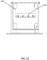
- FIG. 21 illustrates an exemplary tray 2020 with a calibration target 2022.
- a calibration target 2022 at a known position in the tray 2020 which holds the sample plate, and having the calibration target 2022 at a position able to be contacted by the sample probe, may be able to extrapolate the position of the sample probe in relation to a plate resting in the tray 2020.
- the sample probe Since the sample probe provides feedback when it is displaced in the Z-axis, by extending the probe along the Z-axis while monitoring displacement, it provides a means to determine the distance between the Z-axis origin point and the calibration target 2022. By creating a calibration target 2022 of known dimensions and locating it precisely at a known position in the tray 2020, it may be possible to use displacement of the probe in the Z-axis to determine position of the probe in the X-Y plane.
- the sample probe is positioned over the approximate center of the calibration target 2022.
- the sample probe is moved downward until displacement indicates the probe has contacted the calibration target 2022. This may indicate relative height of the calibration target 2022 in relation to the tray.
- the sample probe is moved along the Y-axis a distance of 4 mm.
- the sample probe is extended downward again.
- the displacement is used to determine if the sample probe is still over the calibration target 2022 or has moved off the edge. These steps are repeated until the edge of the calibration target 2022 has been detected.
- the sample probe may be moved in the Y-axis back over the calibration target a distance of 8 mm. This can be repeated using shorter steps of 250 um to provide finer resolution of the sample probe position.
- the sample probe can be moved along the X-axis.
- the method may provide the X, Y coordinates, relative to the X-Y axes of motion, of a corner of the calibration target 2022 which is at a known location on the tray 2020. Using these coordinates, the location of the calibration target 2022, and the dimensions of the tray 2020, a relationship between the sample probe and the sample tray 2020 can be determined.
- the tray width 2020 by utilizing a calibration target 2022 that spans the majority of the tray width 2020, and performing this calibration function across the entire calibration target 2022, it may be possible to detect any discrepancy between the X-Y orientation of the tray 2020 and the X-Y orientation of the axes of motion. If this discrepancy is known, it may be possible to compensate for it when positioning the sample probe. Thus, this may allow for accurate positioning of the sample probe on a sample plate even when the mechanical aspects of the system are not in correct alignment.
- Embodiments of the present invention may be useful in one or more of basic research, pharmaceutical research, and industrial research. Further, they may be especially useful for performing one or more of intracellular immunophenotyping, extracellular immunophenotyping, fluorescent protein analysis, and cell proliferation analysis.
Description
- This application claims the benefit of priority of
U.S. provisional application Serial Nos. 61/449,025 61/490,451, filed May 26, 2011 29/386,708, filed on March 3, 2011 - The present application generally relates to sampling probes, systems, apparatuses, and methods for hi-throughput flow cytometry and/or for processing samples in batches.
- Systems and apparatuses utilizing sample probes are used in numerous fields, including academic and industrial research, bioproduction, and pharmaceutical industries, for example. In general, in these fields, a large numbers of samples need to be processed rapidly and efficiently.
- However, previously, sample probes required separate manipulation and handling of each sample, even when processing multiple samples. Furthermore, extended sample drawing probes often increased the risk of damage to such probes.
- In fields such as in flow cytometry, genetic sequencing, drug discovery, and proteomics, for example, improvements to sample probe systems are desired
WO2008/034914 A2 discloses a prior art dispenser device with an impact force adjustment mechanism for adjusting the force with which a spotting capillary hits a substrate surface. Two repulsing magnets act as a damper. Furthermore, a distance or position measurement for motion control is performed by counting the passage of optical or magnetic markers of the dispensing device. - According to embodiments described herein, there is provided a sampling probe that help address the aforementioned needs.
- According to an exemplary embodiment of the present teachings, there is provided a sample probe with a built-in obstacle detection mechanism that may reduce costs and increase time savings by reducing both instrument downtime and increasing probe position accuracy and durability.
- According to an exemplary embodiment of the present teachings, there is provided a compliant sample probe with position feedback that minimizes damage to the probe in cases of collisions and calibrates the location of the probe in three-dimensional space.
- According to an exemplary embodiment of the present teachings, there is provided a magnet-based probe with opposing magnets that provide force to push the probe back to a normal state after it has been depressed in contact with another object, and a Hall effect sensor that detects a change in magnetic field when the magnets are pushed closer to each other as the probe is depressed from its relaxed position.
- According to an exemplary embodiment of the present teachings, there is provided a sampling probe according to claim 1.
- A restorative spring may include a single magnet, three magnets, or a metal spring, for example. It should be recognized that the restorative spring according to various embodiments described herein may be any object or assembly that can provide sufficient restorative force to return the probe to a relaxed position.
- A sampling system may include: a housing; a Hall effect sensor mounted onto the housing; and a sampling probe inserted into the housing, the sampling probe including an elongated portion and a plurality of magnets inserted onto the elongated portion.
- A plate sampling apparatus may include: a sampling compartment including a tray configured to receive a sample plate configured to include a plurality of samples; and a probe configured to obtain a sample from the sample plate, the probe including a fitting, an elongated portion extending from the fitting, and a restorative spring including a plurality of magnets inserted onto the elongated portion.
- There is provided a hi-throughput cytometry system, including: a flow cytometer configured to acoustically focus a sample in a flowing fluid; and a plate sampler in fluidic communication with the flow cytometer, the plate sampler including: a sampling compartment including a tray configured to receive a sample plate configured to include a plurality of samples, and a probe configured to obtain a sample from the sample plate, the probe including a fitting, an elongated portion extending from the fitting, and a restorative spring including a plurality of magnets inserted onto the elongated portion.
- According to an exemplary embodiment of the present teachings, there is provided a method for obtaining a sample, including: sampling a sample plate including one or more samples in a plate sampler; moving toward the sample plate a probe including a fitting, an elongated portion extending from the fitting, and a restorative spring including at least two opposing magnets inserted onto the elongated portion; sensing a field strength generated by the opposing magnets in the extended position using a Hall effect sensor; detecting an increase in the field strength generated by the opposing magnets using the Hall effect sensor; stopping the motion of the probe toward the sample plate; and obtaining a sample from the one or more samples in the sample plate using a probe including a fitting, an elongated portion extending from the fitting, and a restorative spring including a plurality of magnets inserted onto the elongated portion.
- According to an exemplary embodiment of the present teachings, there is provided a method for obtaining a sample, including: sampling a sample plate including one or more samples in a plate sampler; moving toward the sample plate a probe including a fitting, an elongated portion extending from the fitting, a restoration restorative spring, and a magnet; sensing a field strength generated by the proximity of the magnet in the extended position using a Hall effect sensor; detecting an increase in the field strength generated by the magnet proximity using the Hall effect sensor; stopping the motion of the probe toward the sample plate; and obtaining a sample from the one or more samples in the sample plate using probe assembly.
- There is provided a method for making a sampling probe, including: providing a fitting; assembling onto the fitting an elongated portion extending from the fitting; and inserting onto the elongated portion a restorative spring including a plurality of rare earth magnets.
- There is provided a plate sampler apparatus, including: a loading compartment including a sample probe and a tray, the tray being configured to receive a sample plate configured to include a plurality of samples; a fluidic compartment configured to receive one or more fluid containers; a first access door configured to allow access to the loading compartment; and a second access door configured to allow access to the fluidic compartment.
- There is provided a hi-throughput cytometry system, including: a flow cytometer configured to acoustically focus a sample in a flowing fluid; and a plate sampler in fluidic communication with the flow cytometer.
- There is provided a hi-throughput cytometry system, including: a flow cytometer; and a plate sampler in fluidic communication with the flow cytometer, the plate sampler including: a sample probe and a tray, the tray being configured to receive a sample plate configured to include a plurality of samples; a fluidic compartment configured to receive one or more fluid containers; a first access door configured to allow access to the loading compartment; and a second access door configured to allow access to the fluidic compartment.
- There is provided a hi-throughput cytometry system, including: a flow cytometer; and a plate sampler in fluidic communication with the flow cytometer, the plate sampler including an actuation mechanism configured to move a tray toward a top surface of the plate sampler such that a sample plate may be loaded onto the tray from above the plate sampler.
- The foregoing general description and the following detailed description are exemplary only and are not limiting in any way of the scope of the present teachings. Other embodiments or variations upon embodiments specifically discussed herein, including various combinations of features of embodiments discussed herein, may be realized from the following detailed description or may be learned by practice of the present teachings.
- The accompanying drawings illustrate various exemplary embodiments of the invention. The drawings are exemplary only and are not in any way limiting of the scope of the invention.
-
FIG. 1 is a perspective view of an exemplary plate sampler. -
FIG. 2 is another perspective view of the exemplary plate sampler set forth inFIG. 1 . -
FIG. 3 is a front view of the exemplary plate sampler set forth inFIG. 1 . -
FIG. 4 is a back view of the exemplary plate sampler set forth inFIG. 1 . -
FIG. 5 is a side view of the exemplary plate sampler set forth inFIG. 1 . -
FIG. 6 is another side view of the exemplary plate sampler set forth inFIG. 1 . -
FIG. 7 is a top view of the exemplary plate sampler set forth inFIG. 1 . -
FIG. 8 is a bottom view of the exemplary plate sampler set forth inFIG. 1 . -
FIG. 9 is a perspective view of another exemplary plate sampler. -
FIG. 10 is another perspective view of the exemplary plate sampler set forth inFIG. 9 . -
FIG. 11 is a front view of the exemplary plate sampler set forth inFIG. 9 . -
FIG. 12 is a back view of the exemplary plate sampler set forth inFIG. 9 . -
FIG. 13 is a side view of the exemplary plate sampler set forth inFIG. 9 . -
FIG. 14 is another side view of the exemplary plate sampler set forth inFIG. 9 . -
FIG. 15 is a top view of the exemplary plate sampler set forth inFIG. 9 . -
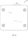
FIG. 16 is a bottom view of the exemplary plate sampler set forth inFIG. 9 . -
FIG. 17 is a schematic diagram of exemplary components of an embodiment of a plate sampler. -
FIG. 18 illustrates an exemplary embodiment of a system for performing hi-throughput flow cytometry. -
FIGS. 19A-19E illustrates exemplary embodiments of sampling probes and systems. -
FIGS. 20A-20B illustrates exemplary embodiments of a system with a calibration target. -
FIG. 21 illustrates an exemplary embodiment of a tray with a calibration target. -
FIGS. 22A-22C illustrates another exemplary embodiment of a plate sampler. - There is provided a plate sampler apparatus, including: a loading compartment including a sample probe and a tray, the tray being configured to receive a sample plate configured to include a plurality of samples; a fluidic compartment configured to receive one or more fluid containers; a first access door configured to allow access to the loading compartment; and a second access door configured to allow access to the fluidic compartment.
- In such an apparatus, the loading compartment may further include an actuation mechanism configured to move the tray. The actuation mechanism may be configured to move the tray, when the first access door is opened, along a direction substantially perpendicular to a direction of gravity between a first position located within the loading compartment and a second position located at least partly outside the loading compartment such that a sample plate may be loaded onto the tray from a side of the apparatus by a user of the apparatus or by robotic machinery. Alternatively, the actuation mechanism may be configured to move the tray, when the first access door is opened, along a direction substantially parallel to a direction of gravity between a first position located within the loading compartment and a second position located at least partly outside the loading compartment such that a sample plate may be loaded onto the tray from above the apparatus by a user of the apparatus or by robotic machinery.
- One or more side portions of the first access door may include one or more indentations configured to hold the tray in place in the second position. A top surface of the apparatus surrounding the first access door may include a recessed area configured to contain spilled fluid. The tray may include a plurality of protruding corners configured to hold a sample plate in place within the tray. The first access door may be arranged within a top surface of the apparatus. The second access door may include one or more windows allowing a user to monitor a fluid level in one or more fluid containers received in the fluidic compartment. The apparatus may further include a plurality of LED indicators. The apparatus may also further include a data transfer port configured to be connected directly to an acoustic flow cytometer or to a computer in communication with an acoustic flow cytometer or to robotic machinery at least partly controlling the apparatus.
-
FIGS. 1-8 illustrate various views of anexemplary plate sampler 100. - The
plate sampler 100 may include asampling compartment 101, which may include asample probe 102 and atray 103. Thetray 103 may be configured to receive a sample plate configured to receive a plurality of samples, and may include one or moreprotruding corners 112 configured to hold the sample plate in place. - The sample plate may be any type of sample plate known in the art. Preferably, the sample plate is a 96-well or 384-well sample plate. The
sampling compartment 101 may further include anactuation mechanism 107 configured to move thetray 103. Theplate sampler 100 may also include afluidic compartment 104, which may be configured to receive one or more fluid containers. Theplate sampler 100 may also include afirst access door 105 configured to allow access to thesampling compartment 101 and asecond access door 106 configured to allow access to thefluidic compartment 104. - The
first access door 105 may be arranged in atop surface 110 of theplate sampler 100, which is especially useful for use with robot or robotic machinery configured to manipulate sample plates. Thefirst access door 105 may be a door that opens by sliding into thetop surface 110 or by rotating about one or more hinge points, and it may include a translucent material or a material substantially preventing light emitted at one or more selected wavelength ranges from reaching the samples in the sample plate, for example. Thefirst access door 105 may also have one ormore side portions 108 including one or more indentations orregistration points 109 configured to hold thetray 103 in place. - The
top surface 110 of the plate sampler may include a recessedarea 111 around thefirst access door 105 that may be configured to contain spilled fluid. Finally, theplate sampler 100 may include one ormore LED indicators 114, one or more data transferports 115, one or more fluid and/or power ports and/orswitches 116, one ormore buttons 117, and/or one or more access panels 118-120. -
FIGS. 9-16 illustrate various views of anotherexemplary plate sampler 200. Theplate sampler 200 may include asampling compartment 201, which may include asample probe 202 and atray 203. Thetray 203 may be configured to receive a sample plate configured to receive a plurality of samples, and may include one or more protruding corners configured to hold the sample plate in place. The sample plate may be any type of sample plate known in the art. For example, the sample plate may be a 96-well, 384-well, 10,000-well, 12,000-well, or 30,000-well sample plate. The sample plate may also contain sample areas that are through-holes. - The
sampling compartment 201 may further include anactuation mechanism 207 configured to move thetray 103. Theplate sampler 200 may also include afluidic compartment 204, which may be configured to receive one or more fluid containers. Theplate sampler 200 may also include afirst access door 205 configured to allow access to thesampling compartment 201 and asecond access door 206 configured to allow access to thefluidic compartment 204. Thefirst access door 205 may be arranged in a side or front surface of theplate sampler 200, may be a door that opens by sliding into the side or front surface or by rotating about one or more hinge points, and/or may include a translucent material or a material substantially preventing light emitted at one or more selected wavelength ranges from reaching the samples in the sample plate, for example. The top surface of theplate sampler 200 may be flat and may include a recessed area configured to contain spilled fluid. Finally, theplate sampler 200 may include one ormore LED indicators 214, one or more data transferports 215, one or more fluid and/or power ports and/orswitches 216, one ormore buttons 217, and/or one or more access panels 218-220.Plate sampler 200 may also include a touch screen capable of displaying a user interface. -
FIGS. 22A-22C illustrate yet anotherplate sampler 2200.FIG. 22A illustrates a perspective front view ofplate sampler 2200.FIG. 22B illustrates another perspective side view ofplate sampler 2200.FIG. 22C illustrates a perspective bottom view ofplate sampler 2200. -
FIG. 17 is a schematic diagram of exemplary components of aplate sampler 1700. Theplate sampler 1700 may include anenclosure 1701 including acontroller board 1702 in communication with one or more other components, which may include one ormore fluid pumps 1703, one or morefluid bottle sensors 1704, one or morefluid bottle LEDs 1705, one ormore status LEDs 1706, and one or more trayactuation feedback systems 1707 configured to actuate one ormore trays 1708. Theplate sampler 1700 may further include one or more of anAC voltage outlet 1709 or any other suitable power outlet, one ormore communication ports 1710 configured to communicate with a computer system, and one ormore communication ports 1711 configured to communicate with a robot, which may include a robotic arm or any type of robotic machinery. Theplate sampler 1700 may further include one or more x-axis control andfeedback systems 1712 for actuating the one ormore trays 1708, one or more y-axis control andfeedback systems 1713 for actuating the one ormore trays 1708, and one or more z-axis control andfeedback systems 1714 for actuating the one ormore trays 1708. -
FIG. 18 illustrates asystem 1800 for performing hi-throughput flow cytometry. Thesystem 1800 may include aflow cytometer 1801, a plate sampler 1802, a robot orrobotic machinery 1803 configured to manipulate sample plates, and a controller orcomputer system 1804 configured to control one or more of these components. Theflow cytometer 1801 may be any flow cytometer known in the art. The robot orrobotic machinery 1803 may be, for example, a robotic arm, or any other device capable of manipulating a sample plate automatically according to instructions corresponding to an experimental or industrial protocol. The controller orcomputer system 1804 may be a separate controller or a controller embedded in one of theflow cytometer 1801, the plate sampler 1802, and the robot orrobotic machinery 1803. The controller orcomputer system 1804 may be any computer system known in the art, including a laptop computer, a desktop computer, and a workstation, and may in particular be any system including a bus, a processor coupled with the bus for processing information, and a memory (e.g., RAM, ROM) or other dynamic storage device for storing information and/or instructions to be executed by the processor. - Preferably, the
flow cytometer 1801 may be an acoustic flow cytometer configured to acoustically focus a sample in a flowing fluid using acoustic energy. For example, the flow cytometer may be an acoustic flow cytometer embodying one or more of the teachings of any one or more ofU.S. Patent No. 7,340,957, issued Mar. 11, 2008 ,U.S. Pat. Appl. Pub. No. 2009/0050573, published Feb. 26, 2009 ,U.S. Pat. Appl. Pub. No. 2009/0053686, published Feb. 26, 2009 ,U.S. Pat. Appl. Pub. No. 2009/0029870, published Jan. 29, 2009 ,U.S. Pat. Appl. Pub. No. 2009/0048805, published Feb. 19, 2009 ,U.S. Pat. Appl. Pub. No. 2009/0042239, published Feb. 12, 2009 ,U.S. Pat. Appl. Pub. No. 2009/0045107, published Feb. 19, 2009 ,U.S. Pat. Appl. Pub. No. 2009/0042310 ,published Feb. 12, 2009 U.S. Pat. Appl. Pub. No. 2009/0178716, published Jul. 16, 2009 ,U.S. Pat. Appl. Pub. No. 2008/0245709, published Oct. 9, 2008 ,U.S. Pat. Appl. Pub. No. 2008/0245745, published Oct. 9, 2008 ,U.S. Pat. Appl. Pub. No. 2009/0162887, published Jun. 25, 2009 ,U.S. Pat. Appl. Pub. No. 2009/0158823, published Jun 25, 2009 , andU.S. Patent Application No. 12/955,282 - The
system 1800 may further include one or morefluidic connections 1805 between theflow cytometer 1801 and the plate sampler 1802, one or more acommunications connections 1806 between the plate sampler 1802 and the robot orrobotic machinery 1803, one or more acommunications connections 1807 between the plate sampler 1802 and the controller orcomputer system 1804, and one ormore communications connections 1808 between theflow cytometer 1801 and the controller orcomputer system 1804. - According to exemplary embodiments described herein, any of the foregoing plate samplers includes a sampling probe according to claim 1.
FIGS. 19A-19E illustrate anexemplary sample probe 1900. - The
sampling probe 1900 or system may include anon-ferrous housing 1902 to minimize interference with magnetic fields and sensors such as aHall sensor 1904. Thehousing 1902 may also include an anodized aluminum housing to provide structural rigidity and corrosion resistance. Thesampling probe 1900 includes arestorative spring 1906. A one magnet restorative spring configuration ofsample probe 1930 according to various teachings not part of the claimed invention is shown inFIG. 19E . - In other embodiments,
restorative spring 1906 includes at least three magnets. Therestorative spring 1906 provides a magnetic field for sensing purposes and for providing a restorative spring restoring force to return the probe to a relaxed position. In some embodiments, thesampling probe 1900 may include at least three magnets. - According to various embodiments described herein, the restorative spring may include three magnets, or a plurality of magnets, for example. It should be recognized that the restorative spring should provide sufficient restorative force to return the probe to a relaxed position.
- The magnet or magnets of the
restorative spring 1906 may be of any magnet type. For example, the magnets may be rare earth magnets to provide for denser field strength and longer magnetic life. Thesampling probe 1900 or system according to the invention also includes aHall effect sensor 1904 to detect magnetic field changes as magnets are pushed together or allowed to move apart. Theprobe 1908 may be used for drawing samples from a sample plate. Theprobe 1908 may be moved by interference with an obstructing object upon detection of changes in Hall effect sensor readings by theHall effect sensor 1904 so as to retract theprobe 1908 from the obstructing object and avoid damage to theprobe 1908. - According to exemplary embodiments of the present teachings, the
probe 1908 may normally be in an extended position with opposing magnets forcing themselves apart and thereby driving theprobe 1908 to the extended position. TheHall effect sensor 1904 may transmit a signal relative to the field strength generated by therestorative spring 1906 in the extended position. As theprobe 1908 is moved toward the sample plate and comes in contact with a surface, the opposing magnets of therestorative spring 1906 are forced together, thereby increasing the field strength sensed by theHall effect sensor 1904 and changing the signal from theHall effect sensor 1904. - This change in signal may be interpreted by the software as motion of the
probe 1908 relative to the rest of the system. The software may then stop the motion of theprobe 1908 so that theprobe 1908 is not damaged by being forced against the interfering object. - According to exemplary embodiments of the present invention, the
probe 1908 is magnet-based and uses aHall effect sensor 1904, which improves reliability and sealing. Although the sensor is aHall effect sensor 1904 that uses a magnetic field for detection, to sense, react, and stop in the event of unexpected contact, any sensor that can sense the displacement of the probe once in contact with a surface could also be used. For example, capacitive, impedance, optical, displacement, pressure, etc, sensors could also be used. Further, although the restoring force for the probe may be magnet-based, other restoring forces may also be used, including a restorative spring, an inductive force generator, or other mechanisms to impose a restoring force on the probe. Magnetic repulsion, however, is particularly useful as it provides a soft restorative force and increases sensor sensitivity by compacting field lines. - According to exemplary embodiments of the present disclosure, when the
probe 1908 is retracted from the interfering object, software may sense the Hall effect signal returning to the steady state value. When the system is in a resting position, the software may calibrate the steady state to the Hall effect signal value, and any changes in magnetic field, position of the probe, or Hall effect sensor may be calibrated out every time the system returns to a rest position. This also allows theprobe 1908 to track and discard any drift in the electronic signal that can occur over longer time periods. Further, knowledge that theprobe 1908 may have touched an object may be used to calibrate all three dimensions of the system. This may be done by moving the probe to a series of known locations with unique three-dimensional coordinates. As the probe touches each known location, the system can calibrate the current position to the known coordinates of that position. Then, by touching several locations, the system can calibrate location in all three operational axes. - In such a sampling probe, the fitting 1910 may include a substantially cylindrical portion having an external teethed surface. The elongated portion may include an interior channel. In other embodiments, the
restorative spring 1906 includes at least three magnets. Therestorative spring 1906 may include at least two magnets having a polarity oriented along a first direction and at least one additional magnet having a polarity oriented along a direction opposite to the first direction. At least one of the at least three magnets may be a rare earth magnet. The magnets may be a rare earth magnet. In some embodiments, thesampling probe 1900 may preferably not include an optical sensor, a non-magnetic metal restorative spring, a strain gage, and electrical contacts. The properties of theHall effect sensor 1904 and therestorative spring 1906 are selected to allow therestorative spring 1906 to provide a restorative force allowing sensing of an obstacle and stopping without damaging a tip of thesampling probe 1900. - Furthermore, when an obstacle is detected, the user may be notified that there was an obstacle and that sampling should not proceed. An error may also be generated and indicated to the user.
- According to an exemplary embodiment of the present teachings, there is provided a sampling system, including: a
housing 1902; aHall effect sensor 1904 mounted onto thehousing 1902; and aprobe 1908 inserted into thehousing 1902, the 1908 probe including an elongated portion and a plurality of magnets, comprising arestorative spring 1906, inserted onto the elongated portion. In various teachings described herein, the plurality of magnets may comprise a single magnet. In other teachings the plurality of magnets may include more than one magnet. - The plurality of magnets may include at least three magnets. The plurality of magnets include at least two magnets having a polarity oriented along a first direction and at least one additional magnet having a polarity oriented along a direction opposite to the first direction. Each of the at least three magnets may be a rare earth magnet.
- In such a sampling system, the
housing 1902 may be selected from one of a non-ferrous housing and an anodized aluminum housing. Thesampling probe 1900 may include a fitting 1910 including a substantially cylindrical portion having an external teethed surface. The elongated portion may include an interior channel. Thesampling probe 1900 may preferably not include an optical sensor, a non-magnetic metal spring, a strain gage, and electrical contacts. The sampling probe orsystem 1900 may further include an analog sensor configured to allow sampling probe drift compensation via calibration of an axis of the sampling probe. Thesampling system 1900 may further include a controller configured to control a movement of thesampling probe 1900 using a stroke of between about 2.5 mm and about 4.5 mm, the stroke including between about 0.75 mm and about 1.25 mm for sensing and between about 0.75 mm and about 1.25 mm for stopping. The stroke may further include between about 0.75 mm and about 1.25 mm for movement noise. The stroke may further include between about 0.25 mm and about 0.75 mm for overstroke. - With reference to
FIG. 9 , according to an exemplary embodiment of the present teachings, there is provided aplate sampling apparatus 200, including: asampling compartment 201 including atray 203 configured to receive a sample plate configured to include a plurality of samples; and aprobe 202 configured to obtain a sample from the sample plate, the probe being according to claim 1. - According to an exemplary embodiment of the present teachings, there is provided a hi-throughput cytometry system, including: a flow cytometer configured to acoustically focus a sample in a flowing fluid; and a plate sampler in fluidic communication with the flow cytometer, the plate sampler including: a sampling compartment including a tray configured to receive a sample plate configured to include a plurality of samples, and a probe (
FIG. 19A ) configured to obtain a sample from the sample plate, thesample probe 1900 being acccording to claim 1. - With reference to
FIG. 19A , there is provided a method for obtaining a sample, including: sampling a sample plate including one or more samples in a plate sampler; moving toward the sample plate a probe including a fitting 1910, an elongated portion extending from the fitting 1910, and arestorative spring 1906 including at least two opposing magnets inserted onto the elongated portion; sensing a field strength generated by the opposing magnets in the extended position using aHall effect sensor 1904; detecting an increase in the field strength generated by the opposing magnets using theHall effect sensor 1904; stopping the motion of theprobe 1908 toward the sample plate; and obtaining a sample from the one or more samples in the sample plate using aprobe 1908 including a fitting 1910, an elongated portion extending from the fitting 1910, and arestorative spring 1906 including a plurality of magnets inserted onto the elongated portion. - Such a method may further include controlling a movement of the probe using a stroke of between about 2.5 mm and about 4.5 mm, the stroke including between about 0.75 mm and about 1.25 mm for sensing, between about 0.75 mm and about 1.25 mm for stopping, between about 0.75 mm and about 1.25 mm for movement noise, and between about 0.25 mm and about 0.75 mm for overstroke. It may also include magnetically retracting the probe upon detection of the increase in the field strength generated by the opposing magnets using the Hall effect sensor. And it may include generating a dimensional calibration signal upon detection of the increase in the field strength generated by the opposing magnets using the Hall effect sensor, and calibrating probe locations along three operational axes.
- There is provided a method for making a sampling probe, including: providing a fitting; assembling onto the fitting an elongated portion extending from the fitting; and inserting onto the elongated portion a restorative spring including a plurality of rare earth magnets.
- In such a plate sampling apparatus, a plate sampler may include: a loading compartment including a sample probe and a tray, the tray being configured to receive a sample plate configured to include a plurality of samples; a fluidic compartment configured to receive one or more fluid containers; a first access door configured to allow access to the loading compartment; and a second access door configured to allow access to the fluidic compartment.
- The loading compartment may further include an actuation mechanism configured to move the tray. The actuation mechanism may be configured to move the tray, when the first access door is opened, along a direction substantially perpendicular to a direction of gravity between a first position located within the loading compartment and a second position located at least partly outside the loading compartment such that a sample plate may be loaded onto the tray from a side of the apparatus. Alternatively, the actuation mechanism is configured to move the tray, when the first access door is opened, along a direction substantially parallel to a direction of gravity between a first position located within the loading compartment and a second position located at least partly outside the loading compartment such that a sample plate may be loaded onto the tray from above the apparatus.
- One or more side portions of the first access door may include one or more indentations configured to hold the tray in place in the second position. A top surface of the apparatus surrounding the first access door may include a recessed area configured to contain spilled fluid. The tray may include a plurality of protruding corners configured to hold a sample plate in place within the tray.
- The system may further comprise robotic machinery configured to transfer one or more fluids and samples to and from one or more sample plates and further configured to spatially manipulate the one or more sample plates so as to insert the one or more sample plates in the tray of the plate sampler; and a controller configured to control the flow cytometer, the plate sampler, and the robotic machinery according to one or more experimental protocols.
- There is provided a hi-throughput cytometry system, including: a flow cytometer; and a plate sampler in fluidic communication with the flow cytometer, the plate sampler including: a sample probe and a tray, the tray being configured to receive a sample plate configured to include a plurality of samples; a fluidic compartment configured to receive one or more fluid containers; a first access door configured to allow access to the loading compartment; and a second access door configured to allow access to the fluidic compartment.
- There is provided a hi-throughput cytometry system, including: a flow cytometer; and a plate sampler in fluidic communication with the flow cytometer, the plate sampler including an actuation mechanism configured to move a tray toward a top surface of the plate sampler such that a sample plate may be loaded onto the tray from above the plate sampler.
- Furthermore, as mentioned above, to provide precise positioning of the sample probe in relation to the sample plate, the sampling device may need to detect, with a high degree of accuracy, the positional relationship between each of its' three axes and the physical position of the sample plate. Because of variations in manufacturing and wear of the axes over time, it is important that the sampling device may also be able to calibrate itself on a periodic basis, to determine the values that correspond to these physical relationships. A sample probe in accordance with embodiments described herein provides a mechanism by which the sampling probe can more accurately determine the position of the sampling probe in relation to the sample plate.
-
FIGS. 20A and20B illustrate an exemplaryplate sampler apparatus 2000 with acalibration target 2022.FIG. 21 illustrates anexemplary tray 2020 with acalibration target 2022. Acalibration target 2022 at a known position in thetray 2020 which holds the sample plate, and having thecalibration target 2022 at a position able to be contacted by the sample probe, may be able to extrapolate the position of the sample probe in relation to a plate resting in thetray 2020. - Since the sample probe provides feedback when it is displaced in the Z-axis, by extending the probe along the Z-axis while monitoring displacement, it provides a means to determine the distance between the Z-axis origin point and the
calibration target 2022. By creating acalibration target 2022 of known dimensions and locating it precisely at a known position in thetray 2020, it may be possible to use displacement of the probe in the Z-axis to determine position of the probe in the X-Y plane. - An example calibration method is described below. First, the sample probe is positioned over the approximate center of the
calibration target 2022. The sample probe is moved downward until displacement indicates the probe has contacted thecalibration target 2022. This may indicate relative height of thecalibration target 2022 in relation to the tray. Next, the sample probe is moved along the Y-axis a distance of 4 mm. The sample probe is extended downward again. The displacement is used to determine if the sample probe is still over thecalibration target 2022 or has moved off the edge. These steps are repeated until the edge of thecalibration target 2022 has been detected. - Further, the sample probe may be moved in the Y-axis back over the calibration target a distance of 8 mm. This can be repeated using shorter steps of 250 um to provide finer resolution of the sample probe position. Once the
calibration target 2022 edge has been determined to the desired accuracy along the Y-axis, the sample probe can be moved along the X-axis. - A similar process in the X-axis is repeated until the
calibration target 2022 edge has been determined in the X-axis. In this way, the method may provide the X, Y coordinates, relative to the X-Y axes of motion, of a corner of thecalibration target 2022 which is at a known location on thetray 2020. Using these coordinates, the location of thecalibration target 2022, and the dimensions of thetray 2020, a relationship between the sample probe and thesample tray 2020 can be determined. - Also, by utilizing a
calibration target 2022 that spans the majority of thetray width 2020, and performing this calibration function across theentire calibration target 2022, it may be possible to detect any discrepancy between the X-Y orientation of thetray 2020 and the X-Y orientation of the axes of motion. If this discrepancy is known, it may be possible to compensate for it when positioning the sample probe. Thus, this may allow for accurate positioning of the sample probe on a sample plate even when the mechanical aspects of the system are not in correct alignment. - Embodiments of the present invention may be useful in one or more of basic research, pharmaceutical research, and industrial research. Further, they may be especially useful for performing one or more of intracellular immunophenotyping, extracellular immunophenotyping, fluorescent protein analysis, and cell proliferation analysis.
- Other embodiments of the invention will be apparent to one of ordinary skill in the art having had the benefit of the present specification and/or having practiced one or more embodiments of the invention. Further, the present specification including the drawings are all exemplary and are not in any way limiting of the scope of the invention, which shall be determined by the following claims.
Claims (10)
- A sampling probe (1900), comprising:a fitting (1910);an elongated portion extending from the fitting; anda restorative spring (1906) including at least two opposing magnets inserted onto the elongated portion,a Hall effect sensor (1904) for determining contact of the probe with a surface by sensing a field strength of the at least two opposing magnets as the magnets are pushed together or allowed to move apart,wherein properties of the Hall effect sensor and the at least two opposing magnets are selected to allow the restorative spring to provide a restorative force allowing sensing of an obstacle and stopping without damaging a tip of the sampling probe.
- The sampling probe of claim 1, wherein the fitting includes a substantially cylindrical portion having an external teethed surface.
- The sampling probe of claim 1, wherein the elongated portion includes an interior channel.
- The sampling probe of claim 1, wherein the restorative spring includes at least three magnets.
- The sampling probe of claim 4, wherein at least one of the at least three magnets is a rare earth magnet.
- The sampling probe of claim 4, wherein each of the at least three magnets is a rare earth magnet.
- The sampling probe of claim 1, wherein the sampling probe does not comprise an optical sensor.
- The sampling probe of claim 1, wherein the sampling probe does not comprise a non-magnetic metal spring.
- The sampling probe of claim 1, wherein the sampling probe does not comprise a strain gage.
- The sampling probe of claim 1, wherein the sampling probe does not comprise electrical contacts.
Applications Claiming Priority (3)
| Application Number | Priority Date | Filing Date | Title |
|---|---|---|---|
| US201161449025P | 2011-03-03 | 2011-03-03 | |
| US201161490451P | 2011-05-26 | 2011-05-26 | |
| PCT/US2012/027580 WO2012119118A2 (en) | 2011-03-03 | 2012-03-02 | Sampling probes, systems, apparatuses, and methods |
Publications (2)
| Publication Number | Publication Date |
|---|---|
| EP2681567A2 EP2681567A2 (en) | 2014-01-08 |
| EP2681567B1 true EP2681567B1 (en) | 2021-04-28 |
Family
ID=45952637
Family Applications (1)
| Application Number | Title | Priority Date | Filing Date |
|---|---|---|---|
| EP12713814.7A Active EP2681567B1 (en) | 2011-03-03 | 2012-03-02 | Sampling probes |
Country Status (6)
| Country | Link |
|---|---|
| US (3) | US9529008B2 (en) |
| EP (1) | EP2681567B1 (en) |
| JP (2) | JP5973471B2 (en) |
| CN (1) | CN103988084B (en) |
| SG (2) | SG10201601482YA (en) |
| WO (1) | WO2012119118A2 (en) |
Families Citing this family (20)
| Publication number | Priority date | Publication date | Assignee | Title |
|---|---|---|---|---|
| US9529008B2 (en) | 2011-03-03 | 2016-12-27 | Life Technologies Corporation | Sampling probes, systems, apparatuses, and methods |
| US10046815B2 (en) * | 2012-03-27 | 2018-08-14 | Wearpro Incorporated | Wear monitoring device and method of monitoring undercarriage and roller wear |
| EP2793031B1 (en) * | 2013-04-15 | 2022-01-05 | Siemens Healthcare Diagnostics Products GmbH | Pipetting system for an analyser |
| EP3209402B1 (en) | 2014-10-24 | 2019-11-20 | Life Technologies Corporation | Acoustically settled liquid-liquid sample purification system |
| CN104764896B (en) * | 2015-03-27 | 2017-03-08 | 苏州长光华医生物医学工程有限公司 | A kind of sample needle anticollision device, collision-prevention device of in-vitro diagnosis equipment |
| CN205907259U (en) | 2015-03-30 | 2017-01-25 | Bd科斯特公司 | A equipment for following culture medium collection sample |
| ES2898175T3 (en) * | 2016-01-22 | 2022-03-04 | Siemens Healthcare Diagnostics Products Gmbh | Adjustment system. |
| JP1571526S (en) * | 2016-08-15 | 2017-03-13 | ||
| CN107044922A (en) * | 2017-01-20 | 2017-08-15 | 广东顺德工业设计研究院(广东顺德创新设计研究院) | Sampler |
| EP3602003A1 (en) | 2017-03-31 | 2020-02-05 | Life Technologies Corporation | Apparatuses, systems and methods for imaging flow cytometry |
| US10613020B2 (en) * | 2017-08-10 | 2020-04-07 | The Boeing Company | Burr detection systems and methods |
| CN111432726A (en) | 2017-11-02 | 2020-07-17 | 米密德诊断学有限公司 | Cartridge and system for analyzing body fluid |
| CN107748269B (en) * | 2017-11-06 | 2020-04-10 | 泰州泽成生物技术有限公司 | Novel automatic alarm and recovery device after sample adding needle impact |
| USD888267S1 (en) * | 2018-04-24 | 2020-06-23 | Memed Diagnostics Ltd. | Diagnostic instrument |
| USD892352S1 (en) * | 2018-06-08 | 2020-08-04 | Delta Electronics, Inc. | Automated nucleic acid analysis detector |
| USD911546S1 (en) * | 2018-12-07 | 2021-02-23 | SeLux Diagnostics, Inc. | Apparatus for medical or laboratory diagnosis |
| DE102018221337A1 (en) * | 2018-12-10 | 2020-06-10 | Vetter Pharma-Fertigung GmbH & Co. KG | Force measuring arrangement, force measuring device with such a force measuring arrangement and method with such a force measuring arrangement |
| CN113711050A (en) * | 2019-05-20 | 2021-11-26 | 深圳迈瑞生物医疗电子股份有限公司 | Sample analyzer and liquid suction control method |
| US20220099634A1 (en) * | 2020-09-30 | 2022-03-31 | Benjamin J. Black | Sample introduction devices and systems and methods of using and producing them |
| JP2024515971A (en) | 2021-04-27 | 2024-04-11 | ライフ テクノロジーズ コーポレーション | Sample injection probe cleaning |
Family Cites Families (80)
| Publication number | Priority date | Publication date | Assignee | Title |
|---|---|---|---|---|
| JPH0198970A (en) * | 1987-10-13 | 1989-04-17 | Konica Corp | Trickling guide for sample liquid trickling device |
| USD319102S (en) | 1988-10-25 | 1991-08-13 | Tabai Espec Kabushiki Kaisha | Carbon dioxide gas incubator |
| JPH03183958A (en) * | 1989-12-13 | 1991-08-09 | Shimadzu Corp | Sampling device |
| DE69126690T2 (en) * | 1990-04-06 | 1998-01-02 | Perkin Elmer Corp | AUTOMATED LABORATORY FOR MOLECULAR BIOLOGY |
| US5562843A (en) * | 1991-12-28 | 1996-10-08 | Joven Electric Co., Ltd. | Industrial robot with contact sensor |
| US5610069A (en) * | 1992-03-27 | 1997-03-11 | Abbott Laboratories | Apparatus and method for washing clinical apparatus |
| US5507410A (en) * | 1992-03-27 | 1996-04-16 | Abbott Laboratories | Meia cartridge feeder |
| US5772962A (en) * | 1995-05-29 | 1998-06-30 | Hitachi, Ltd. | Analyzing apparatus using disposable reaction vessels |
| SE9502183D0 (en) * | 1995-06-15 | 1995-06-15 | Pharmacia Ab | Safety device at a pipette arm |
| USD387164S (en) | 1996-02-07 | 1997-12-02 | Barnett Dale C | Laboratory incubator |
| EP0801309A3 (en) * | 1996-04-08 | 1998-08-12 | SANYO ELECTRIC Co., Ltd. | Pipetting apparatus |
| US5668452A (en) * | 1996-05-09 | 1997-09-16 | Vlsi Technology, Inc. | Magnetic sensing robotics for automated semiconductor wafer processing systems |
| US5989835A (en) * | 1997-02-27 | 1999-11-23 | Cellomics, Inc. | System for cell-based screening |
| US6170343B1 (en) * | 1996-09-09 | 2001-01-09 | Tyco Group S.A.R.L. | Electronically monitored mechanical pipette |
| US5998218A (en) * | 1996-09-09 | 1999-12-07 | Sherwood Services Ag | Calibration system for an electronically monitored mechanical pipette |
| JPH10332733A (en) * | 1997-05-27 | 1998-12-18 | Yaskawa Electric Corp | Acceleration sensor |
| JP2001517788A (en) | 1997-09-25 | 2001-10-09 | マクアリー リサーチ リミテッド | Method and apparatus for removing a specimen from an array of specimens |
| JP3231269B2 (en) * | 1997-11-25 | 2001-11-19 | アロカ株式会社 | Dispensing device |
| EP0961922A1 (en) | 1997-12-23 | 1999-12-08 | Rainin Instrument Co.,Inc. | Manual pipette with magnet assist |
| USD456523S1 (en) | 1998-04-16 | 2002-04-30 | Uvp (Ultra-Violet Products), Inc. | Combination irradiation device and hybridizer |
| CA2273729A1 (en) * | 1998-07-14 | 2000-01-14 | Bayer Corporation | Robotics for transporting containers and objects within an automated analytical instrument and service tool for servicing robotics |
| US6216804B1 (en) * | 1998-07-29 | 2001-04-17 | James T. Aumann | Apparatus for recovering core samples under pressure |
| US6282459B1 (en) * | 1998-09-01 | 2001-08-28 | International Business Machines Corporation | Structure and method for detection of physical interference during transport of an article |
| US6419827B1 (en) * | 1998-10-29 | 2002-07-16 | Applera Corporation | Purification apparatus and method |
| US6890487B1 (en) * | 1999-09-30 | 2005-05-10 | Science & Technology Corporation ©UNM | Flow cytometry for high throughput screening |
| US6532837B1 (en) | 2000-02-03 | 2003-03-18 | Rainin Instrument, Llc | Pipette device with tip ejector utilizing stored energy |
| JP2002062302A (en) * | 2000-08-23 | 2002-02-28 | Sysmex Corp | Sample-dispensing device and autoanalyzer equipped therewith |
| AU2002230966A1 (en) * | 2000-12-18 | 2002-07-01 | Protedyne Corporation | Automated laboratory system and method |
| US6416719B1 (en) * | 2001-01-19 | 2002-07-09 | Gilson, Inc. | Plate locator for precision liquid handler |
| US6669909B2 (en) * | 2001-03-26 | 2003-12-30 | Allegro Technologies Limited | Liquid droplet dispensing |
| CN100418632C (en) * | 2001-05-30 | 2008-09-17 | 比奥莱克斯公司 | Plate and method for high throughput screening |
| US6855538B2 (en) * | 2001-06-27 | 2005-02-15 | The Regents Of The University Of California | High-efficiency microarray printing device |
| JP2004534226A (en) | 2001-06-29 | 2004-11-11 | メソ スケイル テクノロジーズ,エルエルシー | Assay plate, reader system and method for luminescence test measurement |
| US7125722B2 (en) * | 2002-07-03 | 2006-10-24 | Abbott Laboratories | Apparatus and method for handling fluids for analysis |
| EP2306174B1 (en) * | 2003-03-28 | 2016-05-11 | Inguran, LLC | Flow cytometry nozzle for orienting particles and corresponding method |
| JP2004325398A (en) * | 2003-04-28 | 2004-11-18 | Hitachi Software Eng Co Ltd | Needle for continuous suction, and continuous suction device |
| US20050223837A1 (en) * | 2003-11-10 | 2005-10-13 | Blueshift Technologies, Inc. | Methods and systems for driving robotic components of a semiconductor handling system |
| DE102004016003B4 (en) * | 2004-04-01 | 2006-05-04 | Eppendorf Ag | Electronic pipette |
| WO2005114224A1 (en) | 2004-05-07 | 2005-12-01 | Novasite Pharmaceuticals, Inc. | Direct mixing and injection for high throughput fluidic systems |
| DE102004025588B4 (en) | 2004-05-25 | 2006-12-28 | Lre Technology Partner Gmbh | Dosing tip receiver for receiving a dosing tip |
| US7979157B2 (en) * | 2004-07-23 | 2011-07-12 | Mcmaster University | Multi-purpose robotic operating system and method |
| US7340957B2 (en) | 2004-07-29 | 2008-03-11 | Los Alamos National Security, Llc | Ultrasonic analyte concentration and application in flow cytometry |
| US7597520B2 (en) | 2005-05-24 | 2009-10-06 | Festo Corporation | Apparatus and method for transferring samples from a source to a target |
| US20070012113A1 (en) * | 2005-07-18 | 2007-01-18 | Helicos Biosciences Corporation | Non-contact detection |
| US20070092403A1 (en) * | 2005-10-21 | 2007-04-26 | Alan Wirbisky | Compact apparatus, compositions and methods for purifying nucleic acids |
| EP2541257A3 (en) * | 2006-09-22 | 2013-01-16 | CLONDIAG GmbH | A dispenser device for and a method of dispensing a substance onto a substrate |
| WO2008122051A1 (en) | 2007-04-02 | 2008-10-09 | Acoustic Cytometry Systems, Inc. | Methods and devices for enhanced analysis of field focused cells and particles |
| US8083068B2 (en) | 2007-04-09 | 2011-12-27 | Los Alamos National Security, Llc | Apparatus for separating particles utilizing engineered acoustic contrast capture particles |
| US7837040B2 (en) | 2007-04-09 | 2010-11-23 | Los Alamos National Security, Llc | Acoustic concentration of particles in fluid flow |
| JP5038004B2 (en) * | 2007-04-12 | 2012-10-03 | キヤノン株式会社 | Analysis equipment |
| USD634442S1 (en) | 2007-07-11 | 2011-03-15 | Universal Bio Research Co., Ltd. | Apparatus for processing proteins |
| US8726745B2 (en) * | 2007-11-26 | 2014-05-20 | Perkinelmer Health Sciences, Inc. | Fluid handling device with ultrasound sensor and methods and systems using same |
| US8266951B2 (en) | 2007-12-19 | 2012-09-18 | Los Alamos National Security, Llc | Particle analysis in an acoustic cytometer |
| US8714014B2 (en) | 2008-01-16 | 2014-05-06 | Life Technologies Corporation | System and method for acoustic focusing hardware and implementations |
| CA2721327C (en) | 2008-04-11 | 2020-01-07 | Meso Scale Technologies, Llc | Assay apparatuses, methods and reagents |
| US8647594B2 (en) * | 2008-07-18 | 2014-02-11 | Accuri Cytometers, Inc. | Wellplate handler system for a flow cytometer |
| US9034257B2 (en) * | 2008-10-27 | 2015-05-19 | Nodality, Inc. | High throughput flow cytometry system and method |
| DE102008059788B4 (en) * | 2008-12-01 | 2018-03-08 | Olympus Soft Imaging Solutions Gmbh | Analysis and classification of biological or biochemical objects on the basis of time series images, applicable to cytometric time-lapse cell analysis in image-based cytometry |
| JP5157950B2 (en) * | 2009-02-05 | 2013-03-06 | 横河電機株式会社 | Dispensing device |
| WO2010110872A1 (en) * | 2009-03-24 | 2010-09-30 | Perkinelmer Health Sciences, Inc. | System and auto-alignment method for determining position using a discrete contact probe |
| US8986958B2 (en) * | 2009-03-30 | 2015-03-24 | Life Technologies Corporation | Methods for generating target specific probes for solution based capture |
| USD654175S1 (en) | 2009-11-02 | 2012-02-14 | Tagg Design Inc | Sanitizing station |
| EP2430177B1 (en) * | 2009-05-14 | 2018-09-26 | Icubate, Inc. | Apparatus for performing amplicon rescue multiplex pcr |
| DE102009051654B4 (en) * | 2009-10-30 | 2013-01-03 | Eppendorf Ag | Dosing device for liquids and method for dosing liquids |
| CN102762990B (en) | 2009-12-04 | 2014-10-29 | 生命技术公司 | Apparatuses, systems, methods, and computer readable media for acoustic flow cytometry |
| JP5514582B2 (en) * | 2010-02-24 | 2014-06-04 | 株式会社日立製作所 | Liquid suction device |
| US8941062B2 (en) * | 2010-11-16 | 2015-01-27 | 1087 Systems, Inc. | System for identifying and sorting living cells |
| USD668833S1 (en) | 2010-12-21 | 2012-10-09 | Giorgio De Togni | Container for saving biographical and/or biological objects and/or information |
| USD698038S1 (en) | 2011-03-03 | 2014-01-21 | Life Technologies Corporation | Plate loader |
| US9529008B2 (en) | 2011-03-03 | 2016-12-27 | Life Technologies Corporation | Sampling probes, systems, apparatuses, and methods |
| AU2013216878B2 (en) * | 2012-02-09 | 2016-09-29 | Beckman Coulter, Inc. | Sorting flow cytometer |
| WO2013192479A1 (en) * | 2012-06-22 | 2013-12-27 | Bio-Rad Laboratories, Inc. | Multi-directional sorting with reduced contamination in a flow cytometer |
| JP3183958U (en) | 2013-03-28 | 2013-06-06 | 雄悟 池田 | Packed funeral and legal offerings |
| US9446159B2 (en) * | 2013-10-03 | 2016-09-20 | Becton, Dickinson And Company | Flow cytometer biosafety hood and systems including the same |
| EP3071951B1 (en) * | 2013-11-19 | 2019-10-30 | ACEA Biosciences, Inc. | Optical engine for flow cytometer, flow cytometer system and methods of use |
| US9880085B2 (en) * | 2014-03-21 | 2018-01-30 | Intellicyt Corporation | Flow cytometer system including flow cytometer, autosampler and system integration structure |
| JP6280777B2 (en) * | 2014-03-24 | 2018-02-14 | シスメックス株式会社 | Analysis device and liquid level detection method in analysis device |
| US9897531B2 (en) * | 2014-06-03 | 2018-02-20 | Intellicyt | Flow cytometry sample separation methods and apparatus |
| US9869628B2 (en) * | 2014-06-25 | 2018-01-16 | Acea Biosciences, Inc. | Methods of collecting cells from multi-well plates for use in flow cytometry |
| US9797917B2 (en) * | 2014-07-11 | 2017-10-24 | Intellicyt | Contact sensing probe and methods of use for microplate liquid sampling |
-
2012
- 2012-03-02 US US13/411,337 patent/US9529008B2/en active Active
- 2012-03-02 WO PCT/US2012/027580 patent/WO2012119118A2/en active Application Filing
- 2012-03-02 CN CN201280019430.7A patent/CN103988084B/en active Active
- 2012-03-02 EP EP12713814.7A patent/EP2681567B1/en active Active
- 2012-03-02 SG SG10201601482YA patent/SG10201601482YA/en unknown
- 2012-03-02 SG SG2013066261A patent/SG193283A1/en unknown
- 2012-03-02 JP JP2013556659A patent/JP5973471B2/en active Active
-
2016
- 2016-07-14 JP JP2016139414A patent/JP6215405B2/en active Active
- 2016-11-17 US US15/353,828 patent/US10082518B2/en active Active
-
2018
- 2018-08-21 US US16/106,682 patent/US10890596B2/en active Active
Non-Patent Citations (1)
| Title |
|---|
| None * |
Also Published As
| Publication number | Publication date |
|---|---|
| SG10201601482YA (en) | 2016-04-28 |
| WO2012119118A3 (en) | 2016-01-14 |
| US9529008B2 (en) | 2016-12-27 |
| JP2017015714A (en) | 2017-01-19 |
| SG193283A1 (en) | 2013-10-30 |
| EP2681567A2 (en) | 2014-01-08 |
| WO2012119118A9 (en) | 2013-06-20 |
| US20170131316A1 (en) | 2017-05-11 |
| JP2014531016A (en) | 2014-11-20 |
| US10082518B2 (en) | 2018-09-25 |
| CN103988084B (en) | 2017-03-08 |
| US20190086435A1 (en) | 2019-03-21 |
| JP5973471B2 (en) | 2016-08-23 |
| JP6215405B2 (en) | 2017-10-18 |
| US20120227471A1 (en) | 2012-09-13 |
| US10890596B2 (en) | 2021-01-12 |
| WO2012119118A2 (en) | 2012-09-07 |
| CN103988084A (en) | 2014-08-13 |
Similar Documents
| Publication | Publication Date | Title |
|---|---|---|
| US10890596B2 (en) | Sampling probes, systems, apparatuses, and methods | |
| US20200406251A1 (en) | Devices and methods for programmable manipulation of pipettes | |
| JP2014531016A5 (en) | ||
| US9797917B2 (en) | Contact sensing probe and methods of use for microplate liquid sampling | |
| US11506677B2 (en) | Systems and methods for pipette robots | |
| EP3326038B1 (en) | System and method for determining a work offset | |
| CN109416366B (en) | Method for determining the position of a robotic arm of a liquid handling system and corresponding liquid handling system | |
| US9579645B2 (en) | Fluid transfer apparatus | |
| US20070258858A1 (en) | Robotic gripper for transporting multiple object types | |
| JP6304977B2 (en) | In vitro diagnostic system | |
| US20060085162A1 (en) | Laboratory sample transfer apparatus with interchangeable tools | |
| CN113573813A (en) | EWOD cartridge position sensing when docked in an EWOD instrument | |
| US20230305034A1 (en) | Systems and methods for framing workspaces of robotic fluid handling systems |
Legal Events
| Date | Code | Title | Description |
|---|---|---|---|
| PUAI | Public reference made under article 153(3) epc to a published international application that has entered the european phase |
Free format text: ORIGINAL CODE: 0009012 |
|
| 17P | Request for examination filed |
Effective date: 20130924 |
|
| AK | Designated contracting states |
Kind code of ref document: A2 Designated state(s): AL AT BE BG CH CY CZ DE DK EE ES FI FR GB GR HR HU IE IS IT LI LT LU LV MC MK MT NL NO PL PT RO RS SE SI SK SM TR |
|
| DAX | Request for extension of the european patent (deleted) | ||
| R17D | Deferred search report published (corrected) |
Effective date: 20160114 |
|
| RAP1 | Party data changed (applicant data changed or rights of an application transferred) |
Owner name: LIFE TECHNOLOGIES CORPORATION |
|
| STAA | Information on the status of an ep patent application or granted ep patent |
Free format text: STATUS: EXAMINATION IS IN PROGRESS |
|
| 17Q | First examination report despatched |
Effective date: 20200205 |
|
| GRAP | Despatch of communication of intention to grant a patent |
Free format text: ORIGINAL CODE: EPIDOSNIGR1 |
|
| STAA | Information on the status of an ep patent application or granted ep patent |
Free format text: STATUS: GRANT OF PATENT IS INTENDED |
|
| INTG | Intention to grant announced |
Effective date: 20201222 |
|
| GRAS | Grant fee paid |
Free format text: ORIGINAL CODE: EPIDOSNIGR3 |
|
| GRAA | (expected) grant |
Free format text: ORIGINAL CODE: 0009210 |
|
| STAA | Information on the status of an ep patent application or granted ep patent |
Free format text: STATUS: THE PATENT HAS BEEN GRANTED |
|
| AK | Designated contracting states |
Kind code of ref document: B1 Designated state(s): AL AT BE BG CH CY CZ DE DK EE ES FI FR GB GR HR HU IE IS IT LI LT LU LV MC MK MT NL NO PL PT RO RS SE SI SK SM TR |
|
| REG | Reference to a national code |
Ref country code: GB Ref legal event code: FG4D |
|
| REG | Reference to a national code |
Ref country code: CH Ref legal event code: EP |
|
| REG | Reference to a national code |
Ref country code: AT Ref legal event code: REF Ref document number: 1387650 Country of ref document: AT Kind code of ref document: T Effective date: 20210515 |
|
| REG | Reference to a national code |
Ref country code: DE Ref legal event code: R096 Ref document number: 602012075378 Country of ref document: DE |
|
| REG | Reference to a national code |
Ref country code: IE Ref legal event code: FG4D |
|
| REG | Reference to a national code |
Ref country code: LT Ref legal event code: MG9D |
|
| REG | Reference to a national code |
Ref country code: AT Ref legal event code: MK05 Ref document number: 1387650 Country of ref document: AT Kind code of ref document: T Effective date: 20210428 |
|
| PG25 | Lapsed in a contracting state [announced via postgrant information from national office to epo] |
Ref country code: HR Free format text: LAPSE BECAUSE OF FAILURE TO SUBMIT A TRANSLATION OF THE DESCRIPTION OR TO PAY THE FEE WITHIN THE PRESCRIBED TIME-LIMIT Effective date: 20210428 Ref country code: AT Free format text: LAPSE BECAUSE OF FAILURE TO SUBMIT A TRANSLATION OF THE DESCRIPTION OR TO PAY THE FEE WITHIN THE PRESCRIBED TIME-LIMIT Effective date: 20210428 Ref country code: BG Free format text: LAPSE BECAUSE OF FAILURE TO SUBMIT A TRANSLATION OF THE DESCRIPTION OR TO PAY THE FEE WITHIN THE PRESCRIBED TIME-LIMIT Effective date: 20210728 Ref country code: FI Free format text: LAPSE BECAUSE OF FAILURE TO SUBMIT A TRANSLATION OF THE DESCRIPTION OR TO PAY THE FEE WITHIN THE PRESCRIBED TIME-LIMIT Effective date: 20210428 Ref country code: LT Free format text: LAPSE BECAUSE OF FAILURE TO SUBMIT A TRANSLATION OF THE DESCRIPTION OR TO PAY THE FEE WITHIN THE PRESCRIBED TIME-LIMIT Effective date: 20210428 Ref country code: NL Free format text: LAPSE BECAUSE OF FAILURE TO SUBMIT A TRANSLATION OF THE DESCRIPTION OR TO PAY THE FEE WITHIN THE PRESCRIBED TIME-LIMIT Effective date: 20210428 |
|
| PG25 | Lapsed in a contracting state [announced via postgrant information from national office to epo] |
Ref country code: ES Free format text: LAPSE BECAUSE OF FAILURE TO SUBMIT A TRANSLATION OF THE DESCRIPTION OR TO PAY THE FEE WITHIN THE PRESCRIBED TIME-LIMIT Effective date: 20210428 Ref country code: PT Free format text: LAPSE BECAUSE OF FAILURE TO SUBMIT A TRANSLATION OF THE DESCRIPTION OR TO PAY THE FEE WITHIN THE PRESCRIBED TIME-LIMIT Effective date: 20210830 Ref country code: NO Free format text: LAPSE BECAUSE OF FAILURE TO SUBMIT A TRANSLATION OF THE DESCRIPTION OR TO PAY THE FEE WITHIN THE PRESCRIBED TIME-LIMIT Effective date: 20210728 Ref country code: PL Free format text: LAPSE BECAUSE OF FAILURE TO SUBMIT A TRANSLATION OF THE DESCRIPTION OR TO PAY THE FEE WITHIN THE PRESCRIBED TIME-LIMIT Effective date: 20210428 Ref country code: IS Free format text: LAPSE BECAUSE OF FAILURE TO SUBMIT A TRANSLATION OF THE DESCRIPTION OR TO PAY THE FEE WITHIN THE PRESCRIBED TIME-LIMIT Effective date: 20210828 Ref country code: GR Free format text: LAPSE BECAUSE OF FAILURE TO SUBMIT A TRANSLATION OF THE DESCRIPTION OR TO PAY THE FEE WITHIN THE PRESCRIBED TIME-LIMIT Effective date: 20210729 Ref country code: LV Free format text: LAPSE BECAUSE OF FAILURE TO SUBMIT A TRANSLATION OF THE DESCRIPTION OR TO PAY THE FEE WITHIN THE PRESCRIBED TIME-LIMIT Effective date: 20210428 Ref country code: RS Free format text: LAPSE BECAUSE OF FAILURE TO SUBMIT A TRANSLATION OF THE DESCRIPTION OR TO PAY THE FEE WITHIN THE PRESCRIBED TIME-LIMIT Effective date: 20210428 Ref country code: SE Free format text: LAPSE BECAUSE OF FAILURE TO SUBMIT A TRANSLATION OF THE DESCRIPTION OR TO PAY THE FEE WITHIN THE PRESCRIBED TIME-LIMIT Effective date: 20210428 |
|
| REG | Reference to a national code |
Ref country code: NL Ref legal event code: MP Effective date: 20210428 |
|
| PG25 | Lapsed in a contracting state [announced via postgrant information from national office to epo] |
Ref country code: RO Free format text: LAPSE BECAUSE OF FAILURE TO SUBMIT A TRANSLATION OF THE DESCRIPTION OR TO PAY THE FEE WITHIN THE PRESCRIBED TIME-LIMIT Effective date: 20210428 Ref country code: SK Free format text: LAPSE BECAUSE OF FAILURE TO SUBMIT A TRANSLATION OF THE DESCRIPTION OR TO PAY THE FEE WITHIN THE PRESCRIBED TIME-LIMIT Effective date: 20210428 Ref country code: SM Free format text: LAPSE BECAUSE OF FAILURE TO SUBMIT A TRANSLATION OF THE DESCRIPTION OR TO PAY THE FEE WITHIN THE PRESCRIBED TIME-LIMIT Effective date: 20210428 Ref country code: DK Free format text: LAPSE BECAUSE OF FAILURE TO SUBMIT A TRANSLATION OF THE DESCRIPTION OR TO PAY THE FEE WITHIN THE PRESCRIBED TIME-LIMIT Effective date: 20210428 Ref country code: EE Free format text: LAPSE BECAUSE OF FAILURE TO SUBMIT A TRANSLATION OF THE DESCRIPTION OR TO PAY THE FEE WITHIN THE PRESCRIBED TIME-LIMIT Effective date: 20210428 Ref country code: CZ Free format text: LAPSE BECAUSE OF FAILURE TO SUBMIT A TRANSLATION OF THE DESCRIPTION OR TO PAY THE FEE WITHIN THE PRESCRIBED TIME-LIMIT Effective date: 20210428 |
|
| REG | Reference to a national code |
Ref country code: DE Ref legal event code: R097 Ref document number: 602012075378 Country of ref document: DE |
|
| PLBE | No opposition filed within time limit |
Free format text: ORIGINAL CODE: 0009261 |
|
| STAA | Information on the status of an ep patent application or granted ep patent |
Free format text: STATUS: NO OPPOSITION FILED WITHIN TIME LIMIT |
|
| 26N | No opposition filed |
Effective date: 20220131 |
|
| PG25 | Lapsed in a contracting state [announced via postgrant information from national office to epo] |
Ref country code: IS Free format text: LAPSE BECAUSE OF FAILURE TO SUBMIT A TRANSLATION OF THE DESCRIPTION OR TO PAY THE FEE WITHIN THE PRESCRIBED TIME-LIMIT Effective date: 20210828 Ref country code: AL Free format text: LAPSE BECAUSE OF FAILURE TO SUBMIT A TRANSLATION OF THE DESCRIPTION OR TO PAY THE FEE WITHIN THE PRESCRIBED TIME-LIMIT Effective date: 20210428 |
|
| PG25 | Lapsed in a contracting state [announced via postgrant information from national office to epo] |
Ref country code: IT Free format text: LAPSE BECAUSE OF FAILURE TO SUBMIT A TRANSLATION OF THE DESCRIPTION OR TO PAY THE FEE WITHIN THE PRESCRIBED TIME-LIMIT Effective date: 20210428 |
|
| PG25 | Lapsed in a contracting state [announced via postgrant information from national office to epo] |
Ref country code: MC Free format text: LAPSE BECAUSE OF FAILURE TO SUBMIT A TRANSLATION OF THE DESCRIPTION OR TO PAY THE FEE WITHIN THE PRESCRIBED TIME-LIMIT Effective date: 20210428 |
|
| REG | Reference to a national code |
Ref country code: CH Ref legal event code: PL |
|
| REG | Reference to a national code |
Ref country code: BE Ref legal event code: MM Effective date: 20220331 |
|
| PG25 | Lapsed in a contracting state [announced via postgrant information from national office to epo] |
Ref country code: LU Free format text: LAPSE BECAUSE OF NON-PAYMENT OF DUE FEES Effective date: 20220302 Ref country code: LI Free format text: LAPSE BECAUSE OF NON-PAYMENT OF DUE FEES Effective date: 20220331 Ref country code: IE Free format text: LAPSE BECAUSE OF NON-PAYMENT OF DUE FEES Effective date: 20220302 Ref country code: CH Free format text: LAPSE BECAUSE OF NON-PAYMENT OF DUE FEES Effective date: 20220331 |
|
| PG25 | Lapsed in a contracting state [announced via postgrant information from national office to epo] |
Ref country code: BE Free format text: LAPSE BECAUSE OF NON-PAYMENT OF DUE FEES Effective date: 20220331 |
|
| PGFP | Annual fee paid to national office [announced via postgrant information from national office to epo] |
Ref country code: FR Payment date: 20230329 Year of fee payment: 12 |
|
| PGFP | Annual fee paid to national office [announced via postgrant information from national office to epo] |
Ref country code: GB Payment date: 20230321 Year of fee payment: 12 Ref country code: DE Payment date: 20230308 Year of fee payment: 12 |
|
| P01 | Opt-out of the competence of the unified patent court (upc) registered |
Effective date: 20230520 |
|
| PG25 | Lapsed in a contracting state [announced via postgrant information from national office to epo] |
Ref country code: HU Free format text: LAPSE BECAUSE OF FAILURE TO SUBMIT A TRANSLATION OF THE DESCRIPTION OR TO PAY THE FEE WITHIN THE PRESCRIBED TIME-LIMIT; INVALID AB INITIO Effective date: 20120302 |