EP2681468B1 - Electric motor assist for transmission electric oil pump - Google Patents
Electric motor assist for transmission electric oil pump Download PDFInfo
- Publication number
- EP2681468B1 EP2681468B1 EP12711998.0A EP12711998A EP2681468B1 EP 2681468 B1 EP2681468 B1 EP 2681468B1 EP 12711998 A EP12711998 A EP 12711998A EP 2681468 B1 EP2681468 B1 EP 2681468B1
- Authority
- EP
- European Patent Office
- Prior art keywords
- electric motor
- oil pump
- hybrid powertrain
- engine
- input shaft
- Prior art date
- Legal status (The legal status is an assumption and is not a legal conclusion. Google has not performed a legal analysis and makes no representation as to the accuracy of the status listed.)
- Active
Links
- 230000005540 biological transmission Effects 0.000 title claims description 47
- 239000003921 oil Substances 0.000 description 90
- 238000000034 method Methods 0.000 description 7
- 238000002485 combustion reaction Methods 0.000 description 5
- 238000010586 diagram Methods 0.000 description 4
- 230000033001 locomotion Effects 0.000 description 3
- 239000010720 hydraulic oil Substances 0.000 description 2
- 239000000446 fuel Substances 0.000 description 1
- 238000004806 packaging method and process Methods 0.000 description 1
- 238000011084 recovery Methods 0.000 description 1
- 230000006641 stabilisation Effects 0.000 description 1
- 238000011105 stabilization Methods 0.000 description 1
- 230000001360 synchronised effect Effects 0.000 description 1
Images


Classifications
-
- F—MECHANICAL ENGINEERING; LIGHTING; HEATING; WEAPONS; BLASTING
- F16—ENGINEERING ELEMENTS AND UNITS; GENERAL MEASURES FOR PRODUCING AND MAINTAINING EFFECTIVE FUNCTIONING OF MACHINES OR INSTALLATIONS; THERMAL INSULATION IN GENERAL
- F16H—GEARING
- F16H61/00—Control functions within control units of change-speed- or reversing-gearings for conveying rotary motion ; Control of exclusively fluid gearing, friction gearing, gearings with endless flexible members or other particular types of gearing
- F16H61/0021—Generation or control of line pressure
- F16H61/0025—Supply of control fluid; Pumps therefore
- F16H61/0028—Supply of control fluid; Pumps therefore using a single pump driven by different power sources
-
- B—PERFORMING OPERATIONS; TRANSPORTING
- B60—VEHICLES IN GENERAL
- B60K—ARRANGEMENT OR MOUNTING OF PROPULSION UNITS OR OF TRANSMISSIONS IN VEHICLES; ARRANGEMENT OR MOUNTING OF PLURAL DIVERSE PRIME-MOVERS IN VEHICLES; AUXILIARY DRIVES FOR VEHICLES; INSTRUMENTATION OR DASHBOARDS FOR VEHICLES; ARRANGEMENTS IN CONNECTION WITH COOLING, AIR INTAKE, GAS EXHAUST OR FUEL SUPPLY OF PROPULSION UNITS IN VEHICLES
- B60K6/00—Arrangement or mounting of plural diverse prime-movers for mutual or common propulsion, e.g. hybrid propulsion systems comprising electric motors and internal combustion engines ; Control systems therefor, i.e. systems controlling two or more prime movers, or controlling one of these prime movers and any of the transmission, drive or drive units Informative references: mechanical gearings with secondary electric drive F16H3/72; arrangements for handling mechanical energy structurally associated with the dynamo-electric machine H02K7/00; machines comprising structurally interrelated motor and generator parts H02K51/00; dynamo-electric machines not otherwise provided for in H02K see H02K99/00
- B60K6/20—Arrangement or mounting of plural diverse prime-movers for mutual or common propulsion, e.g. hybrid propulsion systems comprising electric motors and internal combustion engines ; Control systems therefor, i.e. systems controlling two or more prime movers, or controlling one of these prime movers and any of the transmission, drive or drive units Informative references: mechanical gearings with secondary electric drive F16H3/72; arrangements for handling mechanical energy structurally associated with the dynamo-electric machine H02K7/00; machines comprising structurally interrelated motor and generator parts H02K51/00; dynamo-electric machines not otherwise provided for in H02K see H02K99/00 the prime-movers consisting of electric motors and internal combustion engines, e.g. HEVs
- B60K6/42—Arrangement or mounting of plural diverse prime-movers for mutual or common propulsion, e.g. hybrid propulsion systems comprising electric motors and internal combustion engines ; Control systems therefor, i.e. systems controlling two or more prime movers, or controlling one of these prime movers and any of the transmission, drive or drive units Informative references: mechanical gearings with secondary electric drive F16H3/72; arrangements for handling mechanical energy structurally associated with the dynamo-electric machine H02K7/00; machines comprising structurally interrelated motor and generator parts H02K51/00; dynamo-electric machines not otherwise provided for in H02K see H02K99/00 the prime-movers consisting of electric motors and internal combustion engines, e.g. HEVs characterised by the architecture of the hybrid electric vehicle
- B60K6/44—Series-parallel type
- B60K6/445—Differential gearing distribution type
-
- F—MECHANICAL ENGINEERING; LIGHTING; HEATING; WEAPONS; BLASTING
- F16—ENGINEERING ELEMENTS AND UNITS; GENERAL MEASURES FOR PRODUCING AND MAINTAINING EFFECTIVE FUNCTIONING OF MACHINES OR INSTALLATIONS; THERMAL INSULATION IN GENERAL
- F16H—GEARING
- F16H2312/00—Driving activities
- F16H2312/14—Going to, or coming from standby operation, e.g. for engine start-stop operation at traffic lights
-
- F—MECHANICAL ENGINEERING; LIGHTING; HEATING; WEAPONS; BLASTING
- F16—ENGINEERING ELEMENTS AND UNITS; GENERAL MEASURES FOR PRODUCING AND MAINTAINING EFFECTIVE FUNCTIONING OF MACHINES OR INSTALLATIONS; THERMAL INSULATION IN GENERAL
- F16H—GEARING
- F16H57/00—General details of gearing
- F16H57/04—Features relating to lubrication or cooling or heating
- F16H57/0434—Features relating to lubrication or cooling or heating relating to lubrication supply, e.g. pumps ; Pressure control
- F16H57/0436—Pumps
- F16H57/0439—Pumps using multiple pumps with different power sources or a single pump with different power sources, e.g. one and the same pump may selectively be driven by either the engine or an electric motor
-
- Y—GENERAL TAGGING OF NEW TECHNOLOGICAL DEVELOPMENTS; GENERAL TAGGING OF CROSS-SECTIONAL TECHNOLOGIES SPANNING OVER SEVERAL SECTIONS OF THE IPC; TECHNICAL SUBJECTS COVERED BY FORMER USPC CROSS-REFERENCE ART COLLECTIONS [XRACs] AND DIGESTS
- Y02—TECHNOLOGIES OR APPLICATIONS FOR MITIGATION OR ADAPTATION AGAINST CLIMATE CHANGE
- Y02T—CLIMATE CHANGE MITIGATION TECHNOLOGIES RELATED TO TRANSPORTATION
- Y02T10/00—Road transport of goods or passengers
- Y02T10/60—Other road transportation technologies with climate change mitigation effect
- Y02T10/62—Hybrid vehicles
Definitions
- the present disclosure relates to a method for assisting a transmission oil pump in a hybrid electric transmission, and more particularly to a method for assisting the transmission oil pump to generate transmission oil pressure rapidly during vehicle start to enable electric propulsion quickly after a crank signal from an operator.
- the viscous nature of the hydraulic oil combined with the small size of the electrically powered oil pump can result in a several second delay from when the hybrid powertrain is activated to the time at which hydraulic pressure reaches sufficient pressures for transmission operation. In some circumstances, it may take over 2.25 seconds from the command to pressurize the hydraulic system until adequate pressure is achieved. In some circumstances, the electrically powered oil pump may be simply incapable of achieving adequate oil pressure without the assistance of the internal combustion engine.
- WO 2006/012995 discloses a hybrid powertrain for a motor vehicle comprising all the features of the preamble of claim 1 and in particular a hydraulic transmission unit, an internal combustion engine that can be connected to the input shaft of the transmission unit by means of a first clutch, a first electric motor, and an oil pump which is used to supply the transmission unit with pressurised oil and is driven by the internal combustion engine or a pump electric motor, wherein the first electric motor is powered and coupled to the oil pump, as required, in order to assist the starting of the pump electric motor.
- An object of the present invention is to provide an improved hybrid powertrain and method of operating the same.
- FIG. 1 is schematic representation of a side view of a hybrid powertrain according to the principles of the present disclosure.
- the hybrid powertrain includes an engine 1, planetary gear set 3, and electric motor 30.
- the engine 1 is connected to the input of the planetary gear set 3 by a transmission input shaft 2.
- the transmission input shaft 2 may be the same shaft as an engine crankshaft or a different shaft.
- the output of the planetary gear set 3 is connected to the electric motor 30 by a transmission shaft 4.
- the planetary gear 3 set may be a planetary gear set or any other type of gear set as required by the operational considerations of the hybrid powertrain.
- the hybrid powertrain may be connected to the rest of the vehicle's drive train in any desired manner.
- the transmission input shaft 2 includes an over-running clutch 5 concentrically mounted upon it.
- the over-running clutch 5 permits free rotational movement between the overrunning clutch 5 and the transmission input shaft 2 in a first direction of rotation, but does not permit any rotation between the over-running clutch 5 and the transmission input shaft 2 in a second, opposite direction of rotation.
- the over-running clutch 5 may spin faster than the transmission input shaft 2 in the first direction of free rotation.
- the over-running clutch 5 may be a free-wheeling clutch, one-way bearing, or any other device that permits rotation between the over-running clutch 5 and the transmission input shaft 2 in the first direction, but not in the opposite direction.
- the hybrid powertrain also includes an oil pump electric motor 10 and an oil pump 20.
- the oil pump electric motor 10 includes an oil pump electric motor rotor 11 coupled to the over-running clutch 5 and an oil pump electric motor stator 12 coupled to the transmission housing 6 of the hybrid powertrain.
- the oil pump 20 includes an oil pump impeller 21 coupled to the over-running clutch 5 and an oil pump housing 22 coupled to the transmission housing 6 of the hybrid powertrain.
- the oil pump electric motor rotor 11, oil pump impeller 21, and over-running clutch 5 are all coupled together and rotate synchronously around the transmission input shaft 2.
- the oil pump electric motor rotor 11, oil pump impeller 21, and over-running clutch 5 all rotate when the oil pump electric motor 10 is powered.
- the oil pump 20 is coupled to transmission hydraulics (not shown) as would be readily understood in the art.
- the engine causes the transmission input shaft 2 to rotate.
- the over-running clutch 5 is engaged while the engine 1 is on and, therefore, rotates synchronously with the transmission input shaft 2.
- the oil pump electric motor 10 is switched off. Rotation of the over-running clutch 5 also rotates the oil pump electric motor rotor 11 and oil pump impeller 21, thereby creating oil pressure to power clutches within the hybrid powertrain and permit the powertrain's operation.
- the oil pump electric motor 10 When the engine 1 is turned off from operation (i.e., "Engine Stop Maneuver"), the oil pump electric motor 10 is activated, thereby causing the oil pump electric motor rotor 11 and over-running clutch 5, to which the oil pump impeller 21 is coupled, to rotate. While the engine 1 is turned off, the engine 1 and transmission input shaft 2 do riot rotate. Meanwhile, the over-running clutch 5 rotates freely about the transmission input shaft 2. Rotation of the oil pump electric motor rotor 11 also rotates the oil pump impeller 21, thereby creating oil pressure and facilitating the operation of the hybrid powertrain.
- the oil pump electric motor 10 may be unable to provide adequate oil pressure to the hybrid powertrain within the desired amount of time.
- the hybrid powertrain of the present disclosure is capable of providing an assist function for the oil pump electric motor 10 during vehicle startup and as otherwise desired.
- Figure 2 is a graph of example rotational speeds of the engine 1, transmission input shaft 2, oil pump electric motor rotor 11, oil pump impeller 21, transmission shaft 4, and electric motor 30.
- the electric motor 30 is activated, thereby, causing the electric motor 30 and transmission shaft 4 to rotate at a first number of rotations per minute (RPM).
- the over-running clutch 5 is engaged by the rotation of the transmission input shaft 2.
- the engine 1 is rotating during the startup method of Figure 2 , the engine 1 is never activated (no-spark or fuel).
- the engine 1 may be selectively disconnected from the transmission input shaft 2 by a clutching mechanism such that it does not rotate during the startup procedure.
- the oil pump electric motor 10 is activated.
- both the oil pump electric motor 10 and electric motor 30 are providing the torque to power the oil pump impeller 21.
- the oil pump electric motor 10 is stabilized and satisfactory oil pressure is generated for the hybrid powertrain.
- the hybrid powertrain now has adequate oil pressure to enable the use of the hybrid powertrain clutches and, thus, enable movement of the vehicle.
- the electric motor 30 is switched off while the oil pump electric motor 10 remains activated and takes over the task of powering the rotation of the oil pump impeller 21 and, thus, of providing oil pressure for the hybrid powertrain.
- the disclosed hybrid powertrain utilizing the electric motor 30 to initially assist the oil pump electric motor 10 in providing adequate oil pressure can reach sufficient oil pressure within less than two seconds. In one exemplary embodiment, adequate oil pressure can be achieved in less than 1.5 seconds. In another exemplary embodiment, adequate oil pressure can be achieved in less than 1.25 seconds. In yet another exemplary embodiment, adequate oil pressure can be achieved in less than one second. Adequate oil pressure may be between 600 and 1,000 kPa, less than 600 kPa, or greater than 600 kPa. In one embodiment, adequate oil pressure may be 600, 700, 800, 900, or 1000 kPa.
- the method of operation of the hybrid powertrain as depicted in Figure 2 allows for the rapid pressurization of the oil within the hybrid powertrain. This allows a vehicle utilizing the hybrid powertrain to be placed into motion more quickly after vehicle start up than a vehicle which relies solely upon the oil pump electric motor to supply the torque to generate oil pressure.
- the method or operation may allow a vehicle utilizing the hybrid powertrain to be driven nearly immediately.
- the electric motor 30 would not be depowered after t 3. Rather, the electric motor 30 would be disconnected from the transmission input shaft 2 by a clutching mechanism or other device, allowing the electric motor 30 to rotate and cause the vehicle to move without rotating the transmission input shaft 2 or engine.
- the oil pump electric motor 10 may be activated before, at the same time as, or at any time after the electric motor 30 is activated.
- Figure 3 is a lever diagram of the hybrid powertrain during the Ramp Up and Stabilize Pump Motor periods.
- lever L 1 during the Ramp Up and Stabilize Pump Motor periods ( t 1 - t 3 in Figure 2 ), the rotation of the electric motor 30 causes the engine 1 and oil pump impeller 21 to rotate.
- torque applied by the electric motor 30 to the oil pump impeller 21 (T Electric Motor) is balanced out by the torque applied by the transmission housing (T Ground ).
- T Electric Motor torque applied by the electric motor 30 to the oil pump impeller 21
- T Ground the transmission housing
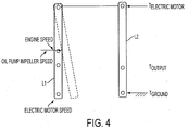
- FIG 4 is a lever diagram of the hybrid powertrain during the Ramp Down and Hydraulic Hand-Off periods.
- lever L 1 As depicted by lever L 1 , during the Ramp Down and Hydraulic Hand-Off periods ( t 3 - t 5 in Figure 2 ), the oil pump electric motor 10 is now powering the oil pump impeller 21 to rotate at the desired RPM without the assistance of the electric motor 30. Neither the engine 1 nor electric motor 30 rotate.
- torque applied by the electric motor 30 to the oil pump impeller 21 T Electric Motor
- T Ground torque applied by the transmission housing
- the electric motor 30 may be used to assist the oil pump electric motor 10 to initially generate oil pressure for the hybrid powertrain. Once a predetermined oil pressure is achieved, the electric motor 30 is disconnected from the oil pump electric motor 10 and the unassisted oil pump electric motor 10 maintains the predetermined oil pressure for the hybrid powertrain. The electric motor 30 can now be used for propulsion or any other function required by the hybrid powertrain.
- the disclosed electric motor assist for the oil pump electric motor may be used with any hybrid powertrain including, but not limited to, a single electric motor hybrid powertrain or two electric motor hybrid powertrain.
- a single electric motor hybrid powertrain or two electric motor hybrid powertrain.
- either electric motor or both electric motors in combination may provide the assist for the oil pump electric motor.
Description
- This application claims the benefit of
U.S. Provisional Serial No. 61/449,136, filed March 4, 2011 - The present disclosure relates to a method for assisting a transmission oil pump in a hybrid electric transmission, and more particularly to a method for assisting the transmission oil pump to generate transmission oil pressure rapidly during vehicle start to enable electric propulsion quickly after a crank signal from an operator.
- Current hybrid powertrain electric motors provide multiple functions including engine start, electric propulsion, electrical energy recovery, and synchronous shift strategy. Many hybrid powertrains allow vehicle operation while the internal combustion engine of the vehicle is completely turned off. To pressurize hydraulic oil, which allows for the operation of the clutches and other devices essential to the operation of the hybrid powertrain, an electrically powered oil pump typically must be operated while the internal combustion engine is switched off. The electrically powered oil pump is typically a small, low power pump for cost, packaging, efficiency and other reasons. Thus, when the hybrid powertrain has been sitting idle for an extended period of time, particularly in colder climates, the viscous nature of the hydraulic oil combined with the small size of the electrically powered oil pump can result in a several second delay from when the hybrid powertrain is activated to the time at which hydraulic pressure reaches sufficient pressures for transmission operation. In some circumstances, it may take over 2.25 seconds from the command to pressurize the hydraulic system until adequate pressure is achieved. In some circumstances, the electrically powered oil pump may be simply incapable of achieving adequate oil pressure without the assistance of the internal combustion engine.
-
WO 2006/012995 discloses a hybrid powertrain for a motor vehicle comprising all the features of the preamble of claim 1 and in particular a hydraulic transmission unit, an internal combustion engine that can be connected to the input shaft of the transmission unit by means of a first clutch, a first electric motor, and an oil pump which is used to supply the transmission unit with pressurised oil and is driven by the internal combustion engine or a pump electric motor, wherein the first electric motor is powered and coupled to the oil pump, as required, in order to assist the starting of the pump electric motor. - An object of the present invention is to provide an improved hybrid powertrain and method of operating the same.
- This object is attained by a hybrid powertrain as claimed in claim 1.
- Further areas of applicability of the present disclosure will become apparent from the detailed description and claims provided hereinafter. It should be understood that the detailed description, including disclosed embodiments and drawings, are merely exemplary in nature intended for purposes of illustration only and are not intended to limit the scope of the invention, its application or use.
-
-
Figure 1 is schematic representation of a side view of the hybrid powertrain according to the principles of the present disclosure; -
Figure 2 is a graph of exemplary rotational speeds of the engine, transmission input shaft, oil pump electric motor rotor, oil pump impeller, and electric motor; -
Figure 3 is a lever diagram of the hybrid powertrain during the ramp up and stabilize pump motor periods; and -
Figure 4 is a lever diagram of the hybrid powertrain during the ramp down and hydraulic hand-off periods. -
Figure 1 is schematic representation of a side view of a hybrid powertrain according to the principles of the present disclosure. The hybrid powertrain includes an engine 1,planetary gear set 3, andelectric motor 30. The engine 1 is connected to the input of theplanetary gear set 3 by atransmission input shaft 2. Thetransmission input shaft 2 may be the same shaft as an engine crankshaft or a different shaft. The output of theplanetary gear set 3 is connected to theelectric motor 30 by a transmission shaft 4. Theplanetary gear 3 set may be a planetary gear set or any other type of gear set as required by the operational considerations of the hybrid powertrain. The hybrid powertrain may be connected to the rest of the vehicle's drive train in any desired manner. - The
transmission input shaft 2 includes an over-runningclutch 5 concentrically mounted upon it. The over-runningclutch 5 permits free rotational movement between theoverrunning clutch 5 and thetransmission input shaft 2 in a first direction of rotation, but does not permit any rotation between the over-runningclutch 5 and thetransmission input shaft 2 in a second, opposite direction of rotation. Thus, the over-runningclutch 5 may spin faster than thetransmission input shaft 2 in the first direction of free rotation. The over-runningclutch 5 may be a free-wheeling clutch, one-way bearing, or any other device that permits rotation between the over-runningclutch 5 and thetransmission input shaft 2 in the first direction, but not in the opposite direction. - The hybrid powertrain also includes an oil pump
electric motor 10 and anoil pump 20. The oil pumpelectric motor 10 includes an oil pumpelectric motor rotor 11 coupled to the over-runningclutch 5 and an oil pumpelectric motor stator 12 coupled to thetransmission housing 6 of the hybrid powertrain. Theoil pump 20 includes anoil pump impeller 21 coupled to the over-runningclutch 5 and anoil pump housing 22 coupled to thetransmission housing 6 of the hybrid powertrain. The oil pumpelectric motor rotor 11,oil pump impeller 21, and over-runningclutch 5 are all coupled together and rotate synchronously around thetransmission input shaft 2. The oil pumpelectric motor rotor 11,oil pump impeller 21, and over-runningclutch 5 all rotate when the oil pumpelectric motor 10 is powered. Theoil pump 20 is coupled to transmission hydraulics (not shown) as would be readily understood in the art. - During vehicle operation with the engine 1 operating, the engine causes the
transmission input shaft 2 to rotate. The over-runningclutch 5 is engaged while the engine 1 is on and, therefore, rotates synchronously with thetransmission input shaft 2. During operation with the engine 1 on, the oil pumpelectric motor 10 is switched off. Rotation of the over-runningclutch 5 also rotates the oil pumpelectric motor rotor 11 andoil pump impeller 21, thereby creating oil pressure to power clutches within the hybrid powertrain and permit the powertrain's operation. - When the engine 1 is turned off from operation (i.e., "Engine Stop Maneuver"), the oil pump
electric motor 10 is activated, thereby causing the oil pumpelectric motor rotor 11 and over-runningclutch 5, to which theoil pump impeller 21 is coupled, to rotate. While the engine 1 is turned off, the engine 1 andtransmission input shaft 2 do riot rotate. Meanwhile, the over-runningclutch 5 rotates freely about thetransmission input shaft 2. Rotation of the oil pumpelectric motor rotor 11 also rotates theoil pump impeller 21, thereby creating oil pressure and facilitating the operation of the hybrid powertrain. - In some operating situations, including cold startup and startup in subzero conditions, the oil pump
electric motor 10 may be unable to provide adequate oil pressure to the hybrid powertrain within the desired amount of time. The hybrid powertrain of the present disclosure is capable of providing an assist function for the oil pumpelectric motor 10 during vehicle startup and as otherwise desired. -
Figure 2 is a graph of example rotational speeds of the engine 1,transmission input shaft 2, oil pumpelectric motor rotor 11,oil pump impeller 21, transmission shaft 4, andelectric motor 30. With reference toFigure 2 , during a vehicle start, initially (t 0 - t 1), none of the components of the hybrid powertrain are rotating. At t 1, theelectric motor 30 is activated, thereby, causing theelectric motor 30 and transmission shaft 4 to rotate at a first number of rotations per minute (RPM). The engine 1,transmission input shaft 2, over-runningclutch 5, oil pumpelectric motor rotor 11,oil pump impeller 21, all connected to theelectric motor 30 through theplanetary gear set 3, rotate at a second RPM. The over-runningclutch 5 is engaged by the rotation of thetransmission input shaft 2. It should be noted that although the engine 1 is rotating during the startup method ofFigure 2 , the engine 1 is never activated (no-spark or fuel). In some embodiments, the engine 1 may be selectively disconnected from thetransmission input shaft 2 by a clutching mechanism such that it does not rotate during the startup procedure. - Between t 1 and t 2 (Ramp Up), the rotational speeds of the
electric motor 30, transmission shaft 4, engine 1,transmission input shaft 2, over-runningclutch 5, oil pumpelectric motor rotor 11,oil pump impeller 21 rapidly increase as a result of the torque being applied by theelectric motor 30. - At t 2, the oil pump
electric motor 10 is activated. Thus, between t 2 and t 3 (Stabilize Pump Motor), both the oil pumpelectric motor 10 andelectric motor 30 are providing the torque to power theoil pump impeller 21. During this time, the oil pumpelectric motor 10 is stabilized and satisfactory oil pressure is generated for the hybrid powertrain. Thus, the hybrid powertrain now has adequate oil pressure to enable the use of the hybrid powertrain clutches and, thus, enable movement of the vehicle. At t 3, theelectric motor 30 is switched off while the oil pumpelectric motor 10 remains activated and takes over the task of powering the rotation of theoil pump impeller 21 and, thus, of providing oil pressure for the hybrid powertrain. Between t 3 and t 4 (Ramp Down), theelectric motor 30, transmission shaft 4, engine 1, andtransmission input shaft 2, all now unpowered, rapidly slow in rotational speed until at t 4, they are no longer rotating. Between t 3 and t 5 (Hydraulic Hand-Off), the oil pumpelectric motor 10, no longer with the assistance of theelectric motor 10, assumes the task of providing oil pressure for the hybrid powertrain and reaches a steady state oil pressure at t 5 (Stabilization). After t 5, the oil pumpelectric motor 10 has stabilized and is capable of providing adequate and consistent oil pressure for the hybrid powertrain without the assistance of theelectric motor 30. - In an exemplary embodiment, the disclosed hybrid powertrain utilizing the
electric motor 30 to initially assist the oil pumpelectric motor 10 in providing adequate oil pressure can reach sufficient oil pressure within less than two seconds. In one exemplary embodiment, adequate oil pressure can be achieved in less than 1.5 seconds. In another exemplary embodiment, adequate oil pressure can be achieved in less than 1.25 seconds. In yet another exemplary embodiment, adequate oil pressure can be achieved in less than one second. Adequate oil pressure may be between 600 and 1,000 kPa, less than 600 kPa, or greater than 600 kPa. In one embodiment, adequate oil pressure may be 600, 700, 800, 900, or 1000 kPa. When using the prior art oil pumpelectric motor 10 without the assistance of theelectric motor 30, adequate and consistent oil pressure for the hybrid powertrain is not reached until t 6 (as indicated by the dashed line inFigure 2 ). The prior art system may take over 2.25 seconds to achieve adequate oil pressure. - The method of operation of the hybrid powertrain as depicted in
Figure 2 allows for the rapid pressurization of the oil within the hybrid powertrain. This allows a vehicle utilizing the hybrid powertrain to be placed into motion more quickly after vehicle start up than a vehicle which relies solely upon the oil pump electric motor to supply the torque to generate oil pressure. In some embodiments, the method or operation may allow a vehicle utilizing the hybrid powertrain to be driven nearly immediately. In such an embodiment, theelectric motor 30 would not be depowered after t 3. Rather, theelectric motor 30 would be disconnected from thetransmission input shaft 2 by a clutching mechanism or other device, allowing theelectric motor 30 to rotate and cause the vehicle to move without rotating thetransmission input shaft 2 or engine. In some embodiments, the oil pumpelectric motor 10 may be activated before, at the same time as, or at any time after theelectric motor 30 is activated. -
Figure 3 is a lever diagram of the hybrid powertrain during the Ramp Up and Stabilize Pump Motor periods. As depicted by lever L1, during the Ramp Up and Stabilize Pump Motor periods (t 1 - t 3 inFigure 2 ), the rotation of theelectric motor 30 causes the engine 1 andoil pump impeller 21 to rotate. As depicted by lever L2, torque applied by theelectric motor 30 to the oil pump impeller 21 (TElectric Motor) is balanced out by the torque applied by the transmission housing (TGround). During this time period, the engine 1 is not activated and does not provide any torque. -
Figure 4 is a lever diagram of the hybrid powertrain during the Ramp Down and Hydraulic Hand-Off periods. As depicted by lever L1, during the Ramp Down and Hydraulic Hand-Off periods (t 3 - t 5 inFigure 2 ), the oil pumpelectric motor 10 is now powering theoil pump impeller 21 to rotate at the desired RPM without the assistance of theelectric motor 30. Neither the engine 1 norelectric motor 30 rotate. The overrunningclutch 5, now disengaged from the rotation of thetransmission input shaft 2, permits the oil pumpelectric motor rotor 11 andoil pump impeller 21 to rotate freely of the transmission input shaft 1. As depicted by lever L2, torque applied by theelectric motor 30 to the oil pump impeller 21 (TElectric Motor) is balanced out by the torque applied by the transmission housing (TGround). - Thus, the
electric motor 30 may be used to assist the oil pumpelectric motor 10 to initially generate oil pressure for the hybrid powertrain. Once a predetermined oil pressure is achieved, theelectric motor 30 is disconnected from the oil pumpelectric motor 10 and the unassisted oil pumpelectric motor 10 maintains the predetermined oil pressure for the hybrid powertrain. Theelectric motor 30 can now be used for propulsion or any other function required by the hybrid powertrain. - The disclosed electric motor assist for the oil pump electric motor may be used with any hybrid powertrain including, but not limited to, a single electric motor hybrid powertrain or two electric motor hybrid powertrain. In a two electric motor hybrid powertrain, either electric motor or both electric motors in combination may provide the assist for the oil pump electric motor.
Claims (5)
- A hybrid powertrain system comprising:an electric motor (30);an over-running clutch (5) coupled to a transmission input shaft (2);an oil pump electric motor (10) coupled to said over-running clutch (5); andan oil pump (20) coupled to said oil pump electric motor (10);said electric motor (30) being configured to rotate said oil pump (20) for a first period of time,characterized by further comprising:a planetary gear set (3) coupled to said electric motor (30) by a transmission shaft (4);the transmission input shaft (2) being coupled to said planetary gear set (3);wherein, after said first period of time, said oil pump electric motor (10) is configured to rotate said oil pump (20) for a second period of time, such that both said electric motor (30) and said oil pump electric motor (10) are rotating said oil pump (20) during said second period of time, andwherein, after said second period of time, said electric motor (30) is configured to be deactivated.
- The hybrid powertrain of claim 1, wherein said over-running clutch (5) is coupled to said electric motor (30) such that said over-running clutch (5) can freely rotate with respect to said electric motor (30) in a first direction of rotation, but fixedly rotates with said electric motor (30) in a second, opposite direction of rotation.
- The hybrid powertrain of Claim 2, further comprising an engine (1) coupled to said transmission input shaft (2), wherein said engine (1) is not activated.
- The hybrid powertrain of Claim 3, wherein said transmission input shaft (2) is selectively coupled to said engine (1).
- The hybrid powertrain of Claim 1, wherein said oil pump (20) achieves an oil pressure of at least approximately 600 kPa in less than approximately 1.25 seconds.
Applications Claiming Priority (2)
| Application Number | Priority Date | Filing Date | Title |
|---|---|---|---|
| US201161449136P | 2011-03-04 | 2011-03-04 | |
| PCT/US2012/027470 WO2012122014A1 (en) | 2011-03-04 | 2012-03-02 | Electric motor assist for transmission electric oil pump |
Publications (2)
| Publication Number | Publication Date |
|---|---|
| EP2681468A1 EP2681468A1 (en) | 2014-01-08 |
| EP2681468B1 true EP2681468B1 (en) | 2019-08-28 |
Family
ID=45929000
Family Applications (1)
| Application Number | Title | Priority Date | Filing Date |
|---|---|---|---|
| EP12711998.0A Active EP2681468B1 (en) | 2011-03-04 | 2012-03-02 | Electric motor assist for transmission electric oil pump |
Country Status (6)
| Country | Link |
|---|---|
| US (1) | US8795118B2 (en) |
| EP (1) | EP2681468B1 (en) |
| CN (1) | CN103547840A (en) |
| BR (1) | BR112013021872B1 (en) |
| CA (1) | CA2828252C (en) |
| WO (1) | WO2012122014A1 (en) |
Families Citing this family (9)
| Publication number | Priority date | Publication date | Assignee | Title |
|---|---|---|---|---|
| EP2594780B1 (en) * | 2011-11-16 | 2023-08-02 | Volvo Car Corporation | Powertrain and method for fast start of an internal combustion engine in a hybrid electric vehicle |
| US9353692B2 (en) * | 2011-12-12 | 2016-05-31 | Fca Us Llc | Start-up strategy for hybrid powertrain |
| JP6209797B2 (en) | 2014-05-20 | 2017-10-11 | 本田技研工業株式会社 | Travel control device |
| KR101601448B1 (en) * | 2014-07-04 | 2016-03-22 | 현대자동차주식회사 | Drive control method and system for electric oil pump |
| US10221856B2 (en) | 2015-08-18 | 2019-03-05 | Bj Services, Llc | Pump system and method of starting pump |
| GB2538591B (en) * | 2016-02-18 | 2019-02-20 | Ford Global Tech Llc | An engine balance assembly using electric motors |
| JP7008689B2 (en) | 2016-09-02 | 2022-01-25 | スタックポール インターナショナル エンジニアード プロダクツ,リミテッド. | Dual input pump and system |
| WO2018101912A1 (en) * | 2016-11-29 | 2018-06-07 | Halliburton Energy Services, Inc. | Dual turbine direct drive pump |
| DE102018219359A1 (en) * | 2018-11-13 | 2020-05-14 | Zf Friedrichshafen Ag | Electric drive unit and transmission for a motor vehicle |
Family Cites Families (6)
| Publication number | Priority date | Publication date | Assignee | Title |
|---|---|---|---|---|
| US6964631B2 (en) * | 2004-02-24 | 2005-11-15 | General Motors Corporation | Integrated electric motor-driven oil pump for automatic transmissions in hybrid applications |
| DE102004036505A1 (en) | 2004-07-28 | 2006-03-16 | Daimlerchrysler Ag | powertrain |
| DE102006033087B4 (en) * | 2006-07-14 | 2022-05-19 | Zf Friedrichshafen Ag | Hybrid drive for a vehicle |
| DE102007043737A1 (en) | 2007-09-13 | 2009-03-26 | Daimler Ag | drive module |
| US8206252B2 (en) * | 2008-05-09 | 2012-06-26 | GM Global Technology Operations LLC | Hybrid powertrain having a multi-speed transmission |
| US8062001B2 (en) * | 2009-04-02 | 2011-11-22 | GM Global Technology Operations LLC | Method for controlling pump transitions in a multi-mode hybrid transmission |
-
2012
- 2012-03-01 US US13/409,388 patent/US8795118B2/en active Active
- 2012-03-02 WO PCT/US2012/027470 patent/WO2012122014A1/en active Application Filing
- 2012-03-02 EP EP12711998.0A patent/EP2681468B1/en active Active
- 2012-03-02 CN CN201280011583.7A patent/CN103547840A/en active Pending
- 2012-03-02 CA CA2828252A patent/CA2828252C/en active Active
- 2012-03-02 BR BR112013021872-0A patent/BR112013021872B1/en not_active IP Right Cessation
Non-Patent Citations (1)
| Title |
|---|
| None * |
Also Published As
| Publication number | Publication date |
|---|---|
| US8795118B2 (en) | 2014-08-05 |
| US20120275930A1 (en) | 2012-11-01 |
| CA2828252C (en) | 2018-06-05 |
| BR112013021872A2 (en) | 2016-10-25 |
| CA2828252A1 (en) | 2012-09-13 |
| EP2681468A1 (en) | 2014-01-08 |
| CN103547840A (en) | 2014-01-29 |
| WO2012122014A1 (en) | 2012-09-13 |
| BR112013021872B1 (en) | 2021-04-13 |
Similar Documents
| Publication | Publication Date | Title |
|---|---|---|
| EP2681468B1 (en) | Electric motor assist for transmission electric oil pump | |
| US9353692B2 (en) | Start-up strategy for hybrid powertrain | |
| US8298105B2 (en) | Hybrid drive device | |
| US7806800B2 (en) | Drive train | |
| CN101318459B (en) | Hybrid powertrain with an engine input clutch and method of control | |
| US20090224557A1 (en) | Engine stop/start system and method of operating same | |
| US9657612B2 (en) | Control system for electric vehicle | |
| EP2277757A3 (en) | Hybrid vehicle start stop control device | |
| US8251166B2 (en) | Hybrid powertrain with assisted starting and method of starting an engine | |
| EP1860012A3 (en) | Engine Start Control | |
| JP2010083230A (en) | Hybrid drive device | |
| WO2010068100A1 (en) | Start system for a combustion engine | |
| JP2002089417A (en) | Engine starter | |
| US8162801B2 (en) | Gear engagement control system and method | |
| EP3555456B1 (en) | A drive system for an engine arrangement | |
| JP3821380B2 (en) | Control system for internal combustion engine for hybrid vehicle | |
| JP2008128097A (en) | Drive device for oil pump | |
| JP6633180B2 (en) | Engine device drive system | |
| JP2010126072A (en) | Controller for hybrid electric vehicle | |
| JP2010083231A (en) | Hybrid drive device | |
| US20110194952A1 (en) | Effort reducing start mechanism for hydraulically propelled vehicles | |
| JP4894475B2 (en) | Engine starter | |
| KR101904256B1 (en) | Starting method and starting device for starting a combustion engine and/or driving a vehicle | |
| JP2004075045A (en) | Device and method for operating auxiliary steering pump to be driven by starter generator | |
| JP4600441B2 (en) | Engine starter |
Legal Events
| Date | Code | Title | Description |
|---|---|---|---|
| PUAI | Public reference made under article 153(3) epc to a published international application that has entered the european phase |
Free format text: ORIGINAL CODE: 0009012 |
|
| 17P | Request for examination filed |
Effective date: 20130925 |
|
| AK | Designated contracting states |
Kind code of ref document: A1 Designated state(s): AL AT BE BG CH CY CZ DE DK EE ES FI FR GB GR HR HU IE IS IT LI LT LU LV MC MK MT NL NO PL PT RO RS SE SI SK SM TR |
|
| DAX | Request for extension of the european patent (deleted) | ||
| STAA | Information on the status of an ep patent application or granted ep patent |
Free format text: STATUS: EXAMINATION IS IN PROGRESS |
|
| 17Q | First examination report despatched |
Effective date: 20180424 |
|
| RIC1 | Information provided on ipc code assigned before grant |
Ipc: B60K 6/48 20071001ALI20120925BHEP Ipc: F16H 61/00 20060101AFI20120925BHEP |
|
| GRAP | Despatch of communication of intention to grant a patent |
Free format text: ORIGINAL CODE: EPIDOSNIGR1 |
|
| STAA | Information on the status of an ep patent application or granted ep patent |
Free format text: STATUS: GRANT OF PATENT IS INTENDED |
|
| INTG | Intention to grant announced |
Effective date: 20190318 |
|
| GRAS | Grant fee paid |
Free format text: ORIGINAL CODE: EPIDOSNIGR3 |
|
| RAP1 | Party data changed (applicant data changed or rights of an application transferred) |
Owner name: FCA US LLC |
|
| GRAA | (expected) grant |
Free format text: ORIGINAL CODE: 0009210 |
|
| STAA | Information on the status of an ep patent application or granted ep patent |
Free format text: STATUS: THE PATENT HAS BEEN GRANTED |
|
| RAP1 | Party data changed (applicant data changed or rights of an application transferred) |
Owner name: FCA US LLC |
|
| AK | Designated contracting states |
Kind code of ref document: B1 Designated state(s): AL AT BE BG CH CY CZ DE DK EE ES FI FR GB GR HR HU IE IS IT LI LT LU LV MC MK MT NL NO PL PT RO RS SE SI SK SM TR |
|
| REG | Reference to a national code |
Ref country code: GB Ref legal event code: FG4D |
|
| REG | Reference to a national code |
Ref country code: CH Ref legal event code: EP |
|
| REG | Reference to a national code |
Ref country code: DE Ref legal event code: R096 Ref document number: 602012063353 Country of ref document: DE |
|
| REG | Reference to a national code |
Ref country code: AT Ref legal event code: REF Ref document number: 1172814 Country of ref document: AT Kind code of ref document: T Effective date: 20190915 |
|
| REG | Reference to a national code |
Ref country code: IE Ref legal event code: FG4D |
|
| REG | Reference to a national code |
Ref country code: NL Ref legal event code: MP Effective date: 20190828 |
|
| REG | Reference to a national code |
Ref country code: LT Ref legal event code: MG4D |
|
| PG25 | Lapsed in a contracting state [announced via postgrant information from national office to epo] |
Ref country code: NO Free format text: LAPSE BECAUSE OF FAILURE TO SUBMIT A TRANSLATION OF THE DESCRIPTION OR TO PAY THE FEE WITHIN THE PRESCRIBED TIME-LIMIT Effective date: 20191128 Ref country code: NL Free format text: LAPSE BECAUSE OF FAILURE TO SUBMIT A TRANSLATION OF THE DESCRIPTION OR TO PAY THE FEE WITHIN THE PRESCRIBED TIME-LIMIT Effective date: 20190828 Ref country code: SE Free format text: LAPSE BECAUSE OF FAILURE TO SUBMIT A TRANSLATION OF THE DESCRIPTION OR TO PAY THE FEE WITHIN THE PRESCRIBED TIME-LIMIT Effective date: 20190828 Ref country code: BG Free format text: LAPSE BECAUSE OF FAILURE TO SUBMIT A TRANSLATION OF THE DESCRIPTION OR TO PAY THE FEE WITHIN THE PRESCRIBED TIME-LIMIT Effective date: 20191128 Ref country code: LT Free format text: LAPSE BECAUSE OF FAILURE TO SUBMIT A TRANSLATION OF THE DESCRIPTION OR TO PAY THE FEE WITHIN THE PRESCRIBED TIME-LIMIT Effective date: 20190828 Ref country code: HR Free format text: LAPSE BECAUSE OF FAILURE TO SUBMIT A TRANSLATION OF THE DESCRIPTION OR TO PAY THE FEE WITHIN THE PRESCRIBED TIME-LIMIT Effective date: 20190828 Ref country code: FI Free format text: LAPSE BECAUSE OF FAILURE TO SUBMIT A TRANSLATION OF THE DESCRIPTION OR TO PAY THE FEE WITHIN THE PRESCRIBED TIME-LIMIT Effective date: 20190828 Ref country code: PT Free format text: LAPSE BECAUSE OF FAILURE TO SUBMIT A TRANSLATION OF THE DESCRIPTION OR TO PAY THE FEE WITHIN THE PRESCRIBED TIME-LIMIT Effective date: 20191230 |
|
| PG25 | Lapsed in a contracting state [announced via postgrant information from national office to epo] |
Ref country code: AL Free format text: LAPSE BECAUSE OF FAILURE TO SUBMIT A TRANSLATION OF THE DESCRIPTION OR TO PAY THE FEE WITHIN THE PRESCRIBED TIME-LIMIT Effective date: 20190828 Ref country code: LV Free format text: LAPSE BECAUSE OF FAILURE TO SUBMIT A TRANSLATION OF THE DESCRIPTION OR TO PAY THE FEE WITHIN THE PRESCRIBED TIME-LIMIT Effective date: 20190828 Ref country code: ES Free format text: LAPSE BECAUSE OF FAILURE TO SUBMIT A TRANSLATION OF THE DESCRIPTION OR TO PAY THE FEE WITHIN THE PRESCRIBED TIME-LIMIT Effective date: 20190828 Ref country code: RS Free format text: LAPSE BECAUSE OF FAILURE TO SUBMIT A TRANSLATION OF THE DESCRIPTION OR TO PAY THE FEE WITHIN THE PRESCRIBED TIME-LIMIT Effective date: 20190828 Ref country code: IS Free format text: LAPSE BECAUSE OF FAILURE TO SUBMIT A TRANSLATION OF THE DESCRIPTION OR TO PAY THE FEE WITHIN THE PRESCRIBED TIME-LIMIT Effective date: 20191228 Ref country code: GR Free format text: LAPSE BECAUSE OF FAILURE TO SUBMIT A TRANSLATION OF THE DESCRIPTION OR TO PAY THE FEE WITHIN THE PRESCRIBED TIME-LIMIT Effective date: 20191129 |
|
| REG | Reference to a national code |
Ref country code: AT Ref legal event code: MK05 Ref document number: 1172814 Country of ref document: AT Kind code of ref document: T Effective date: 20190828 |
|
| PG25 | Lapsed in a contracting state [announced via postgrant information from national office to epo] |
Ref country code: TR Free format text: LAPSE BECAUSE OF FAILURE TO SUBMIT A TRANSLATION OF THE DESCRIPTION OR TO PAY THE FEE WITHIN THE PRESCRIBED TIME-LIMIT Effective date: 20190828 |
|
| PG25 | Lapsed in a contracting state [announced via postgrant information from national office to epo] |
Ref country code: RO Free format text: LAPSE BECAUSE OF FAILURE TO SUBMIT A TRANSLATION OF THE DESCRIPTION OR TO PAY THE FEE WITHIN THE PRESCRIBED TIME-LIMIT Effective date: 20190828 Ref country code: AT Free format text: LAPSE BECAUSE OF FAILURE TO SUBMIT A TRANSLATION OF THE DESCRIPTION OR TO PAY THE FEE WITHIN THE PRESCRIBED TIME-LIMIT Effective date: 20190828 Ref country code: EE Free format text: LAPSE BECAUSE OF FAILURE TO SUBMIT A TRANSLATION OF THE DESCRIPTION OR TO PAY THE FEE WITHIN THE PRESCRIBED TIME-LIMIT Effective date: 20190828 Ref country code: DK Free format text: LAPSE BECAUSE OF FAILURE TO SUBMIT A TRANSLATION OF THE DESCRIPTION OR TO PAY THE FEE WITHIN THE PRESCRIBED TIME-LIMIT Effective date: 20190828 Ref country code: PL Free format text: LAPSE BECAUSE OF FAILURE TO SUBMIT A TRANSLATION OF THE DESCRIPTION OR TO PAY THE FEE WITHIN THE PRESCRIBED TIME-LIMIT Effective date: 20190828 |
|
| PG25 | Lapsed in a contracting state [announced via postgrant information from national office to epo] |
Ref country code: SM Free format text: LAPSE BECAUSE OF FAILURE TO SUBMIT A TRANSLATION OF THE DESCRIPTION OR TO PAY THE FEE WITHIN THE PRESCRIBED TIME-LIMIT Effective date: 20190828 Ref country code: IS Free format text: LAPSE BECAUSE OF FAILURE TO SUBMIT A TRANSLATION OF THE DESCRIPTION OR TO PAY THE FEE WITHIN THE PRESCRIBED TIME-LIMIT Effective date: 20200224 Ref country code: SK Free format text: LAPSE BECAUSE OF FAILURE TO SUBMIT A TRANSLATION OF THE DESCRIPTION OR TO PAY THE FEE WITHIN THE PRESCRIBED TIME-LIMIT Effective date: 20190828 Ref country code: CZ Free format text: LAPSE BECAUSE OF FAILURE TO SUBMIT A TRANSLATION OF THE DESCRIPTION OR TO PAY THE FEE WITHIN THE PRESCRIBED TIME-LIMIT Effective date: 20190828 |
|
| REG | Reference to a national code |
Ref country code: DE Ref legal event code: R097 Ref document number: 602012063353 Country of ref document: DE |
|
| PLBE | No opposition filed within time limit |
Free format text: ORIGINAL CODE: 0009261 |
|
| STAA | Information on the status of an ep patent application or granted ep patent |
Free format text: STATUS: NO OPPOSITION FILED WITHIN TIME LIMIT |
|
| PG2D | Information on lapse in contracting state deleted |
Ref country code: IS |
|
| 26N | No opposition filed |
Effective date: 20200603 |
|
| PG25 | Lapsed in a contracting state [announced via postgrant information from national office to epo] |
Ref country code: SI Free format text: LAPSE BECAUSE OF FAILURE TO SUBMIT A TRANSLATION OF THE DESCRIPTION OR TO PAY THE FEE WITHIN THE PRESCRIBED TIME-LIMIT Effective date: 20190828 |
|
| PG25 | Lapsed in a contracting state [announced via postgrant information from national office to epo] |
Ref country code: MC Free format text: LAPSE BECAUSE OF FAILURE TO SUBMIT A TRANSLATION OF THE DESCRIPTION OR TO PAY THE FEE WITHIN THE PRESCRIBED TIME-LIMIT Effective date: 20190828 |
|
| REG | Reference to a national code |
Ref country code: CH Ref legal event code: PL |
|
| REG | Reference to a national code |
Ref country code: BE Ref legal event code: MM Effective date: 20200331 |
|
| PG25 | Lapsed in a contracting state [announced via postgrant information from national office to epo] |
Ref country code: LU Free format text: LAPSE BECAUSE OF NON-PAYMENT OF DUE FEES Effective date: 20200302 |
|
| PG25 | Lapsed in a contracting state [announced via postgrant information from national office to epo] |
Ref country code: LI Free format text: LAPSE BECAUSE OF NON-PAYMENT OF DUE FEES Effective date: 20200331 Ref country code: CH Free format text: LAPSE BECAUSE OF NON-PAYMENT OF DUE FEES Effective date: 20200331 Ref country code: IE Free format text: LAPSE BECAUSE OF NON-PAYMENT OF DUE FEES Effective date: 20200302 |
|
| PG25 | Lapsed in a contracting state [announced via postgrant information from national office to epo] |
Ref country code: BE Free format text: LAPSE BECAUSE OF NON-PAYMENT OF DUE FEES Effective date: 20200331 |
|
| GBPC | Gb: european patent ceased through non-payment of renewal fee |
Effective date: 20200302 |
|
| PG25 | Lapsed in a contracting state [announced via postgrant information from national office to epo] |
Ref country code: GB Free format text: LAPSE BECAUSE OF NON-PAYMENT OF DUE FEES Effective date: 20200302 |
|
| PG25 | Lapsed in a contracting state [announced via postgrant information from national office to epo] |
Ref country code: IT Free format text: LAPSE BECAUSE OF NON-PAYMENT OF DUE FEES Effective date: 20200302 |
|
| PGFP | Annual fee paid to national office [announced via postgrant information from national office to epo] |
Ref country code: DE Payment date: 20220329 Year of fee payment: 11 |
|
| PG25 | Lapsed in a contracting state [announced via postgrant information from national office to epo] |
Ref country code: MT Free format text: LAPSE BECAUSE OF FAILURE TO SUBMIT A TRANSLATION OF THE DESCRIPTION OR TO PAY THE FEE WITHIN THE PRESCRIBED TIME-LIMIT Effective date: 20190828 Ref country code: CY Free format text: LAPSE BECAUSE OF FAILURE TO SUBMIT A TRANSLATION OF THE DESCRIPTION OR TO PAY THE FEE WITHIN THE PRESCRIBED TIME-LIMIT Effective date: 20190828 |
|
| PGFP | Annual fee paid to national office [announced via postgrant information from national office to epo] |
Ref country code: FR Payment date: 20220325 Year of fee payment: 11 |
|
| PG25 | Lapsed in a contracting state [announced via postgrant information from national office to epo] |
Ref country code: MK Free format text: LAPSE BECAUSE OF FAILURE TO SUBMIT A TRANSLATION OF THE DESCRIPTION OR TO PAY THE FEE WITHIN THE PRESCRIBED TIME-LIMIT Effective date: 20190828 |
|
| REG | Reference to a national code |
Ref country code: DE Ref legal event code: R119 Ref document number: 602012063353 Country of ref document: DE |
|
| PG25 | Lapsed in a contracting state [announced via postgrant information from national office to epo] |
Ref country code: FR Free format text: LAPSE BECAUSE OF NON-PAYMENT OF DUE FEES Effective date: 20230331 Ref country code: DE Free format text: LAPSE BECAUSE OF NON-PAYMENT OF DUE FEES Effective date: 20231003 |