EP2680653A1 - Verfahren zur Handhabung der Ressourcenzuweisung in TDD-System und zugehörige Kommunikationsvorrichtung - Google Patents
Verfahren zur Handhabung der Ressourcenzuweisung in TDD-System und zugehörige Kommunikationsvorrichtung Download PDFInfo
- Publication number
- EP2680653A1 EP2680653A1 EP13165943.5A EP13165943A EP2680653A1 EP 2680653 A1 EP2680653 A1 EP 2680653A1 EP 13165943 A EP13165943 A EP 13165943A EP 2680653 A1 EP2680653 A1 EP 2680653A1
- Authority
- EP
- European Patent Office
- Prior art keywords
- subframe
- configuration
- network
- measurement
- communication device
- Prior art date
- Legal status (The legal status is an assumption and is not a legal conclusion. Google has not performed a legal analysis and makes no representation as to the accuracy of the status listed.)
- Ceased
Links
Images


Classifications
-
- H—ELECTRICITY
- H04—ELECTRIC COMMUNICATION TECHNIQUE
- H04W—WIRELESS COMMUNICATION NETWORKS
- H04W72/00—Local resource management
- H04W72/04—Wireless resource allocation
- H04W72/044—Wireless resource allocation based on the type of the allocated resource
- H04W72/0446—Resources in time domain, e.g. slots or frames
-
- H—ELECTRICITY
- H04—ELECTRIC COMMUNICATION TECHNIQUE
- H04W—WIRELESS COMMUNICATION NETWORKS
- H04W72/00—Local resource management
- H04W72/20—Control channels or signalling for resource management
-
- H—ELECTRICITY
- H04—ELECTRIC COMMUNICATION TECHNIQUE
- H04L—TRANSMISSION OF DIGITAL INFORMATION, e.g. TELEGRAPHIC COMMUNICATION
- H04L1/00—Arrangements for detecting or preventing errors in the information received
- H04L1/0001—Systems modifying transmission characteristics according to link quality, e.g. power backoff
- H04L1/0023—Systems modifying transmission characteristics according to link quality, e.g. power backoff characterised by the signalling
- H04L1/0026—Transmission of channel quality indication
-
- H—ELECTRICITY
- H04—ELECTRIC COMMUNICATION TECHNIQUE
- H04L—TRANSMISSION OF DIGITAL INFORMATION, e.g. TELEGRAPHIC COMMUNICATION
- H04L1/00—Arrangements for detecting or preventing errors in the information received
- H04L1/12—Arrangements for detecting or preventing errors in the information received by using return channel
- H04L1/16—Arrangements for detecting or preventing errors in the information received by using return channel in which the return channel carries supervisory signals, e.g. repetition request signals
- H04L1/18—Automatic repetition systems, e.g. Van Duuren systems
- H04L1/1829—Arrangements specially adapted for the receiver end
- H04L1/1854—Scheduling and prioritising arrangements
-
- H—ELECTRICITY
- H04—ELECTRIC COMMUNICATION TECHNIQUE
- H04W—WIRELESS COMMUNICATION NETWORKS
- H04W72/00—Local resource management
- H04W72/20—Control channels or signalling for resource management
- H04W72/23—Control channels or signalling for resource management in the downlink direction of a wireless link, i.e. towards a terminal
Definitions
- the present invention relates to a method used in a wireless communication system and related communication device, and more particularly, to a method of handling resource allocation in a time-division duplexing (TDD) system and related communication device.
- TDD time-division duplexing
- LTE long-term evolution
- 3GPP 3rd Generation Partnership Project
- 3GPP Rel-8 3rd Generation Partnership Project
- 3GPP Rel-9 3rd Generation Partnership Project
- UMTS universal mobile telecommunications system
- the LTE system includes a new radio interface and a new radio network architecture that provides a high data rate, low latency, packet optimization, and improved system capacity and coverage.
- a radio access network known as an evolved universal terrestrial radio access network (E-UTRAN) includes multiple evolved Node-Bs (eNBs) for communicating with multiple user equipments (UEs), and communicating with a core network including a mobility management entity (MME), a serving gateway, etc., for Non-Access Stratum (NAS) control.
- E-UTRAN evolved universal terrestrial radio access network
- eNBs evolved Node-Bs
- MME mobility management entity
- serving gateway etc.
- NAS Non-Access Stratum
- LTE-advanced (LTE-A) system is an evolution of the LTE system.
- the LTE-A system targets faster switching between power states, improves performance at the coverage edge of an eNB, and includes advanced techniques, such as carrier aggregation (CA), coordinated multipoint transmission/reception (CoMP), UL multiple-input multiple-output (MIMO), etc.
- CA carrier aggregation
- CoMP coordinated multipoint transmission/reception
- MIMO multiple-input multiple-output
- the UE and the eNB must support standards developed for the LTE-A system, such as the 3GPP Rel-10 standard or later versions.
- the subframes in the same frequency band are divided into uplink (UL) subframes, downlink (DL) subframes and special subframes according to the UL/DL configuration specified in the 3GPP standard.
- Fig. 1 is a table 10 of the UL/DL configuration with subframes and corresponding directions.
- Fig. 1 7 UL/DL configurations are shown, wherein each of the UL/DL configurations indicates a set of directions for 10 subframes, respectively.
- U means that the subframe is a UL subframe where UL data is transmitted
- D means that the subframe is a DL subframe where DL data is transmitted
- S means that the subframe is a special subframe where control information and maybe data (according to the special subframe configuration) is transmitted, and the special subframe can also be seen as the DL subframe in the present invention.
- a UL/DL configuration of a legacy UE can be changed according to system information (e.g., System Information Block Type 1 (SIB1)) transmitted by an eNB, e.g., from the UL/DL configuration 1 to the UL/DL configuration 3.
- SIB1 System Information Block Type 1
- a minimum periodicity of transmitting the SIB1 is usually large (e.g., 640 ms), and the legacy UE can only change the UL/DL configuration with the periodicity greater than 640 ms.
- the semi-statics allocation cannot match fast varying traffic characteristics and environments, and there is space for improving system performance.
- changing the UL/DL configuration with a lower periodicity e.g., lower than 640 ms
- the legacy UE is configured with a UL/DL configuration according to the SIB1, and this UL/DL configuration is also known by an advanced UE which is configured with an additional UL/DL configuration.
- the additional configuration is a real configuration operated by the eNB, and the eNB provides services (i.e., performs transmissions and/or receptions) to both the legacy UE and the advanced UE according to the additional configuration.
- the advanced UE transfers from a first UL/DL configuration to a second UL/DL configuration (i.e., real configuration)
- a second UL/DL configuration i.e., real configuration
- the advanced UE intends to perform a transmission in a DL subframe determined according to the second UL/DL configuration, or to perform a reception in a UL subframe according to the second UL/DL configuration.
- This causes a conflict, since the advanced UE should perform the transmission in the UL subframe and perform the reception in the DL subframe.
- the legacy UE may lose scheduling opportunity in a subframe, since the legacy UE does not know the real configuration and the eNB need to provide backward compatibility to the legacy UE.
- the eNB may not schedule the legacy UE to perform a transmission or reception in the subframe, when directions of the subframe determined according to the UL/DL configuration of the legacy UE and the real configuration are different, i.e., when the conflict occurs.
- operations of the legacy UE and the network are affected, and resource may be wasted.
- the application aims at providing a method and a communication device for handling resource allocation in a time-division duplexing (TDD) system to solve the abovementioned problem.
- TDD time-division duplexing
- the claimed method of handling resource allocation for a network of a wireless communication system comprises configuring a direction of a subframe of a frame, when the direction determined according to a first uplink (UL)/downlink (DL) configuration operated by a communication device of the wireless communication system and the direction determined according to a second UL/DL configuration operated by the network are different, when the subframe is a UL subframe determined according to the first UL/DL configuration, or when the subframe is the DL subframe determined according to the first UL/DL configuration but at least for the communication device is not valid for performing a measurement; and performing a transmission or reception with the communication device in the subframe.
- UL uplink
- DL downlink
- Fig. 2 is a schematic diagram of a wireless communication system 20 according to an example of the present invention.
- the wireless communication system 20 is briefly composed of a network, advanced user equipments (UEs) and a legacy UE.
- the wireless communication system 20 supports a time-division duplexing (TDD) mode. That is, the network and the UEs can communicate with each other by using uplink (UL) subframes and downlink (DL) subframes according to one or more UL/DL configurations.
- UL uplink
- DL downlink
- a minimum periodicity for changing an UL/DL configuration of the advanced UE is smaller than a minimum periodicity for changing a UL/DL configuration of the legacy UE.
- the advanced UE can change its UL/DL configuration fast according to fast varying traffic characteristics and environments.
- the advanced UE know the UL/DL configuration of the legacy UE, e.g., according to System Information Block Type 1 (SIB1) transmitted by the network.
- SIB1 System Information Block Type 1
- the advanced UE refers to a communication device supporting the 3rd Generation Partnership Project (3GPP) Rel-11 standard or later versions.
- 3GPP 3rd Generation Partnership Project
- the legacy UE may also have functions similar to those supported by the advanced UE via an update, and is not limited herein.
- the network and the UEs are simply utilized for illustrating the structure of the wireless communication system 20.
- the network can be a universal terrestrial radio access network (UTRAN) comprising a plurality of Node-Bs (NBs) in a universal mobile telecommunications system (UMTS).
- UTRAN universal terrestrial radio access network
- UMTS universal mobile telecommunications system
- the network can be an evolved UTRAN (E-UTRAN) comprising a plurality of evolved NBs (eNBs) and/or relays in a long term evolution (LTE) system, a LTE-Advanced (LTE-A) system or an evolution of the LTE-A system.
- LTE long term evolution
- LTE-A LTE-Advanced
- the network can also include both the UTRAN/E-UTRAN and a core network, wherein the core network includes network entities such as Mobility Management Entity (MME), Serving Gateway (S-GW), Packet Data Network (PDN) Gateway (P-GW), Self-Organizing Networks (SON) server and/or Radio Network Controller (RNC), etc.
- MME Mobility Management Entity
- S-GW Serving Gateway
- PDN Packet Data Network
- P-GW Packet Data Network Gateway
- SON Self-Organizing Networks
- RNC Radio Network Controller
- the UTRAN/E-UTRAN may forward the information to the core network, and the decisions corresponding to the information are made at the core network after the core network processes the information.
- the information can be processed by both the UTRAN/E-UTRAN and the core network, and the decisions are made after coordination and/or cooperation are performed by the UTRAN/E-UTRAN and the core network.
- a UE can be a mobile phone, a laptop, a tablet computer, an electronic book or a portable computer system.
- the network and the UE can be seen as a transmitter or a receiver according to direction, e.g., for an uplink (UL), the UE is the transmitter and the network is the receiver, and for a downlink (DL), the network is the transmitter and the UE is the receiver. More specifically, for the network, the direction of the transmission is DL, and the direction of the reception is UL. For the UE, the direction of the transmission is UL, and the direction of the reception is DL.
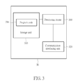
- Fig. 3 is a schematic diagram of a communication device 30 according to an example of the present invention.
- the communication device 30 can be an advanced UE, the legacy UE or the network shown in Fig. 2 , but is not limited herein.
- the communication device 30 may include a processing means 300 such as a microprocessor or Application Specific Integrated Circuit (ASIC), a storage unit 310 and a communication interfacing unit 320.
- the storage unit 310 may be any data storage device that can store a program code 314, accessed and executed by the processing means 300.
- Examples of the storage unit 310 include but are not limited to a subscriber identity module (SIM), read-only memory (ROM), flash memory, random-access memory (RAM), CD-ROM/DVD-ROM, magnetic tape, hard disk and optical data storage device.
- SIM subscriber identity module
- ROM read-only memory
- RAM random-access memory
- CD-ROM/DVD-ROM magnetic tape
- hard disk hard disk
- optical data storage device examples include but are not limited to a subscriber identity module (SIM), read-only memory (ROM), flash memory, random-access memory (RAM), CD-ROM/DVD-ROM, magnetic tape, hard disk and optical data storage device.
- the communication interfacing unit 320 is preferably a transceiver and is used to transmit and receive signals (e.g., messages or packets) according to processing results of the processing means 300.
- Fig. 4 is a flowchart of a process 40 according to an example of the present invention.
- the process 40 is utilized in the network shown in Fig. 2 , for handling resource allocation in the TDD mode, to communicate with the legacy UE.
- the process 40 may be compiled into the program code 314 and includes the following steps:
- the network configures a direction of a subframe of a frame, when the direction determined according to a first UL/DL configuration operated by a communication device of the wireless communication system (e.g., the legacy UE shown in Fig. 2 ) and the direction determined according to a second UL/DL configuration operated by the network are different, when the subframe is a UL subframe determined according to the first UL/DL configuration, or when the subframe is the DL subframe according to the first UL/DL configuration but at least for the communication device is not valid for performing a measurement. Then, then network performs a transmission or reception with the communication device in the subframe.
- a communication device of the wireless communication system e.g., the legacy UE shown in Fig. 2
- the network may reconfigure the direction of the subframe, if one of the abovementioned conditions is satisfied.
- the transmission or reception may include a UL grant and/or a hybrid automatic repeat request (HARQ) feedback triggered by at least one previous transmission or reception performed in at least one previous subframe of a previous frame according to the first UL/DL configuration.
- HARQ hybrid automatic repeat request
- the subframe is not valid for performing the measurement, when the subframe is a Multimedia Broadcast Multicast Service (MBMS) subframe (i.e., Multicast-Broadcast Single Frequency Network (MBSFN) subframe).
- MBMS Multimedia Broadcast Multicast Service
- MBSFN Multicast-Broadcast Single Frequency Network
- the first UL/DL configuration can be a SIB1 configuration.
- the communication device can be the legacy UE which can only change or configure its UL/DL configuration according to the SIB1 transmitted by the network.
- the network can configure the direction of the subframe by configuring the direction of the subframe to a direction of the subframe of the first UL/DL configuration.
- the measurement mentioned above can include a channel state information (CSI) measurement, a radio resource management (RRM) measurement, or a radio link management (RLM) measurement.
- CSI channel state information
- RRM radio resource management
- RLM radio link management
- Fig. 5 is a schematic diagram of subframe allocation of the UL/DL configuration according to an example of the invention.
- the UL/DL configuration 1 is operated by the legacy UE, and the UL/DL configuration 2 is operated by the network (and the advanced UE).
- the legacy UE does not know the real configuration (i.e., the UL/DL configuration 2).
- Rules for performing triggered receptions (receiving e.g., HARQ feedbacks) in the subframes of the frame (n+1) are represented by directions in the same row as shown in region 500 of Fig. 5 .
- the triggered reception performed in the subframe 2 of the frame (n+1) according to the UL/DL configuration 1 corresponds to the transmissions performed in the subframes 5 and/or 6 of the frame n according to the UL/DL configuration 1.
- the legacy UE performs a triggered transmission corresponding to (e.g., triggered by) a reception performed in the subframe 9 of the frame n according to the UL/DL configuration 1
- the triggered transmission will not be received by the network since the network only performs the reception in the UL subframe and the subframe 3 of the frame (n+1) is the DL frame determined according to the UL/DL configuration 2 as shown in region 502 of Fig. 5 .
- the network treats the subframe 3 of the frame (n+1) as the UL subframe according to the present invention, i.e., according to the first condition of step 402. That is, the network will configure the subframe 3 of the frame (n+1) as the UL subframe, such that the triggered transmission performed by the legacy UE in the subframe 3 of the frame (n+1) can be received by the network.
- the conflict occurred due that the UL/DL configurations of the network and the legacy UE are different is solved, and the network and the legacy UE can operate regularly.
- Fig. 6 is a schematic diagram of subframe allocation of the UL/DL configuration according to an example of the invention.
- the UL/DL configuration 3 is operated by the legacy UE, and the UL/DL configuration 4 is operated by the network (and the advanced UE).
- the legacy UE does not know the real configuration (i.e., the UL/DL configuration 4). If the legacy UE performs a transmission in the subframe 4 of the frame n according to the UL/DL configuration 3, the transmission will not be received by the network since the network only performs the reception in the UL subframe and the subframe 4 of the frame n is the DL frame determined according to the UL/DL configuration 4.
- the network treats the subframe 4 of the frame n as the UL subframe according to the present invention, i.e., according to the first condition of step 402. That is, the network will configure the subframe 4 of the frame n as the UL subframe, such that the transmission performed by the legacy UE in the subframe 4 of the frame n can be received by the network.
- the conflict occurred due that the UL/DL configurations of the network and the legacy UE are different is solved, and the network and the legacy UE can operate regularly.
- Fig. 7 is a flowchart of a process 70 according to an example of the present invention.
- the process 70 is utilized in the network shown in Fig. 2 , for handling resource allocation in the TDD mode.
- the process 70 may be compiled into the program code 314 and includes the following steps:
- the network configures a SIB1 configuration as an UL/DL configuration 1, and configures at least one DL subframe of the UL/DL configuration 1 as a subframe type not for performing a measurement. That is, the network configures the UL/DL configuration 1 to the legacy UE, since the SIB1 configuration is usually operated by the legacy UE. Besides, the network may configure a subframe 4 of the UL/DL configuration 1 as the subframe type not for performing the measurement. In another example, the network may configure the subframe 4 and a subframe 9 of the UL/DL configuration 1 as the subframe type not for performing the measurement. That is, both the subframes 4 and 9 are not valid for performing the measurement.
- the measurement can include a CSI measurement, a RRM measurement, or a RLM measurement.
- the network can simply configure the subframe as a MBMS subframe. Thus, the impact of the difference of the UL/DL configurations on the legacy UE can be reduced.
- the legacy UE cannot perform the reception (i.e., receiving the DL data) in the subframe 9 except not performing the measurement in the subframe 9.
- the legacy UE can perform the reception and the measurement in the subframe 9 if the real configuration is not the UL/DL configuration 0.
- the real configuration is the UL/DL configuration 0 (i.e., the subframe 9 is the UL subframe)
- the legacy UE receives nothing and a wrong result may be obtained after performing the measurement.
- the legacy UE can only receive DL data in the subframes 0 and 5 in the worst case (i.e., both the subframes 4 and 9 are configured as the MBMS subframes, and the special subframe is not used for transmitting the DL data), if the legacy UE is configured with the UL/DL configuration 1. If only the subframe 4 is configured as the MBMS subframe, the legacy UE gets one more subframe (i.e., the subframe 9) for performing the reception, and the DL throughput is improved. However, the legacy UE receives nothing and obtains the wrong result after performing the measurement, if the real configuration is the UL/DL configuration 0. Thus, there is a tradeoff between the DL throughput and the accuracy of the measurement.
- the network may exclude the configuration 0 from the set of UL/DL configurations, to avoid obtaining the wrong result from the measurement and to increase a number of DL subframes (e.g., for transmitting/receiving DL data).
- Fig. 8 is a flowchart of a process 80 according to an example of the present invention.
- the process 80 is utilized in the network shown in Fig. 2 , for selecting a UL/DL configuration in the TDD mode.
- the process 80 may be compiled into the program code 314 and includes the following steps:
- the network first selects a UL/DL configuration for a communication device of the wireless communication system (e.g., the legacy UE and/or the advanced UE). Then, the network configures a DL subframe of the UL/DL configuration as a subframe type not for performing a measurement, if a subframe of a plurality of UL/DL configurations corresponding to the DL subframe is a UL subframe, wherein the plurality of UL/DL configurations are configured for performing configuration transfer (i.e., traffic adaptation).
- the UL/DL configuration can be a SIB1 configuration. That is, the network determines the UL/DL configuration for the legacy UE and also for the advanced UE which does not perform the configuration transfer.
- the measurement can include a CSI measurement, a RRM measurement, or a RLM measurement.
- the network can simply configure the subframe as a MBMS subframe.
- the communication device operating the UL/DL configuration will not perform the measurement in the DL subframe and get a wrong result, when the DL subframe is actually a UL frame determined according to one of the plurality of UL/DL configurations which is currently operated by the network.
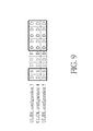
- Fig. 9 is a schematic diagram of subframe allocation of the UL/DL configuration according to an example of the invention.
- UL/DL configurations 3, 4 and 5 are considered for performing configuration transfer. That is, each of the UL/DL configurations can be selected by the network as a SIB1 configuration (e.g., for the legacy UE and also for the advanced UE which does not perform the configuration transfer) and/or a real configuration (for the network and the advanced UE).
- SIB1 configuration e.g., for the legacy UE and also for the advanced UE which does not perform the configuration transfer
- a real configuration for the network and the advanced UE.
- the network configures the subframes 3 and 4 as the MBMS subframes since the subframe 3 of the UL/DL configurations 3 and 4 is the UL subframe and the subframe 4 of the UL/DL configuration 3 is the UL subframe.
- the network selects the UL/DL configuration 4 as the SIB1 configuration, the network configures the subframe 4 as the MBMS subframe since the subframe 4 of the UL/DL configuration 3 is the UL subframe.
- the network selects the UL/DL configuration 3 as the SIB1 configuration, the network does not need to configure any DL subframe, since all subframes of the UL/DL configurations 3, 4 and 5 corresponding to the DL subframes of the UL/DL configuration 3 are DL subframes.
- the legacy UE can perform a transmission, a reception and/or the measurement in each subframe.
- the legacy UE will not perform the measurement in a DL subframe which is actually a UL subframe according to the above examples.
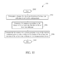
- Fig. 10 is a flowchart of a process 100 according to an example of the present invention.
- the process 100 is utilized in the network shown in Fig. 2 , for handling resource allocation in the TDD mode.
- the process 100 may be compiled into the program code 314 and includes the following steps:
- the network determines a change (e.g., update) of at least one direction of at least one subframe of an UL/DL configuration, and generates a bit sequence according to the change of the at least one direction of the at least one subframe. Then, the network transmits the bit sequence to a communication device of the wireless communication system (e.g., the legacy UE or the advanced UE shown in Fig. 2 ), to indicate the change of the at least one direction of the at least one subframe to the communication device. In other words, the network represents the change of the direction of one or more subframes by using the bit sequence.
- a communication device of the wireless communication system e.g., the legacy UE or the advanced UE shown in Fig. 2
- the communication device identifies the change of the direction according to the bit sequence, and performs transmissions or receptions in the subframes according to the changed direction.
- the communication device can know a direction of a subframe, and the conflict occurred due to different directions of the subframe can be solved.
- the bit sequence can be a bitmap, and at least one bit of the bitmap corresponding to the at least one subframe is bit "1" (or bit "0"), and the rest bit of the bitmap is bit 0 (or bit "1").
- the bit sequence can be a UL extension message, and each type of the UL extension message uniquely corresponds to a type of the change of the at least one direction of the at least one subframe.
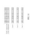
- Fig. 11 is a schematic diagram of subframe allocation of the UL/DL configuration according to an example of the invention.
- Fig. 11 is used for illustrating ways of indicating a change of a direction of a subframe by using the bitmap indicator or the UL extension message.
- the network and the communication device e.g., the advanced UE or the legacy UE
- the network intends to change directions of one or more subframes according to the UL/DL configuration 2.
- 3 cases of configuring the transmission directions of the subframes are considered. That is, the network can change the directions of the subframes in 3 ways in the present example. In the case 1, the network only changes the direction of the subframe 3.
- the network changes the directions of the subframes 3 and 4.
- the network changes the directions of the subframes 3, 4 and 8.
- bit "1" (or bit “0") can be used for representing that the direction of the corresponding subframe is changed while bit "0" (or bit “1") is used for representing that the direction of the corresponding subframe remains unchanged. That is, the network can transmit 10 bits "0001000000”, “0001100000” or "0001100010" to the communication device, to indicate the case 1, 2 or 3, respectively, to the communication device.
- the network can transmit 6 bits "010000", "011000” or "011010” to the communication device, to indicate the case 1, 2 or 3, respectively, to the communication device.
- the network can transmit 3 bits "001 ", "010” or "011” to the communication device, to indicate the case 1, 2 or 3, respectively, to the communication device.
- the network can indicate the transmission direction of the subframe when needed according to the above description. Although only 3 cases are considered in the present example, this is not a restriction. Those skilled in the art can readily extend the above example to examples with more cases, e.g., by changing more bits in the bitmap indicator, or using the UL extension message with more bits.
- the abovementioned steps of the processes including suggested steps can be realized by means that could be a hardware, a firmware known as a combination of a hardware device and computer instructions and data that reside as read-only software on the hardware device, or an electronic system.
- hardware can include analog, digital and mixed circuits known as microcircuit, microchip, or silicon chip.
- the electronic system can include a system on chip (SOC), system in package (SiP), a computer on module (COM), and the communication device 30.
- SOC system on chip
- SiP system in package
- COM computer on module
- the present invention provides a method for handling resource allocation in the TDD mode.
- the conflict occurred due to different UL/DL configurations of the advanced UE, the legacy UE and the network or the transfer of the UL/DL configuration is solved. Further, the change of the UL/DL configuration can be indicated to the communication device efficiently according to the present invention.
Landscapes
- Engineering & Computer Science (AREA)
- Computer Networks & Wireless Communication (AREA)
- Signal Processing (AREA)
- Mobile Radio Communication Systems (AREA)
Applications Claiming Priority (2)
| Application Number | Priority Date | Filing Date | Title |
|---|---|---|---|
| US201261641310P | 2012-05-02 | 2012-05-02 | |
| US13/873,167 US20130294359A1 (en) | 2012-05-02 | 2013-04-29 | Method of Handling Resource Allocation in TDD System and Related Communication Device |
Publications (1)
| Publication Number | Publication Date |
|---|---|
| EP2680653A1 true EP2680653A1 (de) | 2014-01-01 |
Family
ID=49512468
Family Applications (1)
| Application Number | Title | Priority Date | Filing Date |
|---|---|---|---|
| EP13165943.5A Ceased EP2680653A1 (de) | 2012-05-02 | 2013-04-30 | Verfahren zur Handhabung der Ressourcenzuweisung in TDD-System und zugehörige Kommunikationsvorrichtung |
Country Status (3)
| Country | Link |
|---|---|
| US (1) | US20130294359A1 (de) |
| EP (1) | EP2680653A1 (de) |
| TW (1) | TWI472254B (de) |
Families Citing this family (4)
| Publication number | Priority date | Publication date | Assignee | Title |
|---|---|---|---|---|
| EP2871900B1 (de) * | 2012-07-05 | 2019-11-27 | Sony Corporation | Kommunikationssteuerungsvorrichtung, kommunikationssteuerungsverfahren, programm, endgerät und kommunikationssteuerungssystem |
| US8976698B2 (en) * | 2012-08-09 | 2015-03-10 | Qualcomm Incorporated | Methods and apparatus for radio link monitoring in new carrier type (NCT) in a long term evolution (LTE) system |
| WO2016201739A1 (zh) * | 2015-06-16 | 2016-12-22 | 华为技术有限公司 | 资源调度的方法、装置和设备 |
| WO2019127243A1 (zh) | 2017-12-28 | 2019-07-04 | 北京小米移动软件有限公司 | 确定传输方向信息的方法及装置 |
Family Cites Families (3)
| Publication number | Priority date | Publication date | Assignee | Title |
|---|---|---|---|---|
| US9294219B2 (en) * | 2008-09-30 | 2016-03-22 | Qualcomm Incorporated | Techniques for supporting relay operation in wireless communication systems |
| US20110176461A1 (en) * | 2009-12-23 | 2011-07-21 | Telefonakatiebolaget Lm Ericsson (Publ) | Determining configuration of subframes in a radio communications system |
| CN102026209B (zh) * | 2010-12-21 | 2014-04-16 | 大唐移动通信设备有限公司 | 一种传输信息和配置子帧的方法、系统及设备 |
-
2013
- 2013-04-29 US US13/873,167 patent/US20130294359A1/en not_active Abandoned
- 2013-04-30 EP EP13165943.5A patent/EP2680653A1/de not_active Ceased
- 2013-05-02 TW TW102115774A patent/TWI472254B/zh active
Non-Patent Citations (6)
| Title |
|---|
| ALCATEL-LUCENT SHANGHAI BELL ET AL: "Discussion on HARQ and UL-grant timing with dynamic TDD UL-DL configuration", 3GPP DRAFT; R1-121260 DISCUSSION ON HARQ AND UL-GRANT TIMING WITH DYNAMIC TDD UL-DL CONFIGURATION, 3RD GENERATION PARTNERSHIP PROJECT (3GPP), MOBILE COMPETENCE CENTRE ; 650, ROUTE DES LUCIOLES ; F-06921 SOPHIA-ANTIPOLIS CEDEX ; FRANCE, vol. RAN WG1, no. Jeju, Korea; 20120326 - 20120330, 20 March 2012 (2012-03-20), XP050599549 * |
| HUAWEI ET AL: "Backward compatibility for TDD eIMTA", vol. RAN WG1, no. Chicago, USA; 20130415 - 20130419, 6 April 2013 (2013-04-06), XP050696885, Retrieved from the Internet <URL:http://www.3gpp.org/ftp/tsg_ran/WG1_RL1/TSGR1_72b/Docs/> [retrieved on 20130406] * |
| HUAWEI ET AL: "Potential signaling enhancements for TDD eIMTA", vol. RAN WG1, no. St. Julian; 20130128 - 20130201, 19 January 2013 (2013-01-19), XP050663728, Retrieved from the Internet <URL:http://www.3gpp.org/ftp/tsg_ran/WG1_RL1/TSGR1_72/Docs/> [retrieved on 20130119] * |
| INTEL CORPORATION: "Remaining issues of CA for different TDD UL-DL configurations", 3GPP DRAFT; R1-121531, 3RD GENERATION PARTNERSHIP PROJECT (3GPP), MOBILE COMPETENCE CENTRE ; 650, ROUTE DES LUCIOLES ; F-06921 SOPHIA-ANTIPOLIS CEDEX ; FRANCE, vol. RAN WG1, no. Jeju, Korea; 20120326 - 20120330, 20 March 2012 (2012-03-20), XP050599804 * |
| LG ELECTRONICS: "Issues in Further Enhancements to LTE TDD", 3GPP DRAFT; R1-121461 ETDD ISSUES, 3RD GENERATION PARTNERSHIP PROJECT (3GPP), MOBILE COMPETENCE CENTRE ; 650, ROUTE DES LUCIOLES ; F-06921 SOPHIA-ANTIPOLIS CEDEX ; FRANCE, vol. RAN WG1, no. Jeju, Korea; 20120326 - 20120330, 20 March 2012 (2012-03-20), XP050599742 * |
| SAMSUNG: "CRS presence in flexible subframes", vol. RAN WG1, no. Chicago, USA; 20130415 - 20130419, 5 April 2013 (2013-04-05), XP050696714, Retrieved from the Internet <URL:http://www.3gpp.org/ftp/tsg_ran/WG1_RL1/TSGR1_72b/Docs/> [retrieved on 20130405] * |
Also Published As
| Publication number | Publication date |
|---|---|
| US20130294359A1 (en) | 2013-11-07 |
| TWI472254B (zh) | 2015-02-01 |
| TW201347588A (zh) | 2013-11-16 |
Similar Documents
| Publication | Publication Date | Title |
|---|---|---|
| US9807747B2 (en) | Method of handling downlink control information and related communication device | |
| EP2706804B1 (de) | Verfahren zur Handhabung eines erweiterten physischen Downlink-Steuerungskanals | |
| EP3349502B1 (de) | Vorrichtungen zur handhabung von kanalstatusinformationsberichten zur übertragung von zeitintervallen | |
| US9807746B2 (en) | Method of handling hybrid automatic repeat request feedback and related communication device | |
| EP2696529B1 (de) | Verfahren zur Handhabung des Kommunikationsbetriebs in einem TDD-System und zugehörige Vorrichtung | |
| CN110710252B (zh) | 无线通信系统中终端的d2d操作方法和使用所述方法的终端 | |
| EP2750308A2 (de) | Bestimmung und Anzeige der Anzahl der zur Erreichung eines CQI-Levels benötigten Referenzressourcen | |
| US20190037563A1 (en) | Method And System For Transmitting Information About Transmission Mode, Network Device, And Terminal Device | |
| US9107214B2 (en) | Method of handling hybrid automatic repeat request acknowledgement responses in wireless communication system | |
| TW201242286A (en) | Base station device, mobile terminal device, and communication control method | |
| US9722719B2 (en) | Method of handling HARQ resource in TDD system and related communication device | |
| US9706547B2 (en) | Method of handling communication operations and related communication device | |
| US9590770B2 (en) | Method of handling hybrid automatic repeat request feedback and related communication device | |
| US9635645B2 (en) | Method of handling resource allocation in TDD system and related communication device | |
| EP2680653A1 (de) | Verfahren zur Handhabung der Ressourcenzuweisung in TDD-System und zugehörige Kommunikationsvorrichtung | |
| US9867061B2 (en) | Method of handling measurement pattern for TDD system and related communication device | |
| US9160475B2 (en) | Method of handling HARQ resource in TDD system and related communication device | |
| EP2675100B1 (de) | Verfahren zur Anzeige eines Downlink-Steuerkanals und Kommunikationsvorrichtung dafür | |
| CN118235496A (zh) | 对于侧行链路通信的调度 | |
| JP2024514525A (ja) | 動的マルチスロット物理ダウンリンク共有チャネル(pdsch)のための改良型ハイブリッド自動再送要求(harq)フィードバック |
Legal Events
| Date | Code | Title | Description |
|---|---|---|---|
| PUAI | Public reference made under article 153(3) epc to a published international application that has entered the european phase |
Free format text: ORIGINAL CODE: 0009012 |
|
| AK | Designated contracting states |
Kind code of ref document: A1 Designated state(s): AL AT BE BG CH CY CZ DE DK EE ES FI FR GB GR HR HU IE IS IT LI LT LU LV MC MK MT NL NO PL PT RO RS SE SI SK SM TR |
|
| AX | Request for extension of the european patent |
Extension state: BA ME |
|
| 17P | Request for examination filed |
Effective date: 20140623 |
|
| RBV | Designated contracting states (corrected) |
Designated state(s): AL AT BE BG CH CY CZ DE DK EE ES FI FR GB GR HR HU IE IS IT LI LT LU LV MC MK MT NL NO PL PT RO RS SE SI SK SM TR |
|
| STAA | Information on the status of an ep patent application or granted ep patent |
Free format text: STATUS: EXAMINATION IS IN PROGRESS |
|
| 17Q | First examination report despatched |
Effective date: 20170221 |
|
| STAA | Information on the status of an ep patent application or granted ep patent |
Free format text: STATUS: EXAMINATION IS IN PROGRESS |
|
| STAA | Information on the status of an ep patent application or granted ep patent |
Free format text: STATUS: THE APPLICATION HAS BEEN REFUSED |
|
| 18R | Application refused |
Effective date: 20211127 |