EP2680381B1 - Verfahren zur Herstellung eines offenen oder geschlossenen und insbesondere mehrkammerigen Hohlprofils - Google Patents
Verfahren zur Herstellung eines offenen oder geschlossenen und insbesondere mehrkammerigen Hohlprofils Download PDFInfo
- Publication number
- EP2680381B1 EP2680381B1 EP12174391.8A EP12174391A EP2680381B1 EP 2680381 B1 EP2680381 B1 EP 2680381B1 EP 12174391 A EP12174391 A EP 12174391A EP 2680381 B1 EP2680381 B1 EP 2680381B1
- Authority
- EP
- European Patent Office
- Prior art keywords
- cable
- sheet
- hollow profile
- friction
- locked
- Prior art date
- Legal status (The legal status is an assumption and is not a legal conclusion. Google has not performed a legal analysis and makes no representation as to the accuracy of the status listed.)
- Not-in-force
Links
- 238000004519 manufacturing process Methods 0.000 title claims description 9
- 238000000034 method Methods 0.000 claims description 40
- 239000002184 metal Substances 0.000 claims description 19
- 239000012790 adhesive layer Substances 0.000 claims description 4
- 238000005520 cutting process Methods 0.000 description 4
- 238000003466 welding Methods 0.000 description 4
- 229910000831 Steel Inorganic materials 0.000 description 2
- 239000000853 adhesive Substances 0.000 description 2
- 230000001070 adhesive effect Effects 0.000 description 2
- 238000005452 bending Methods 0.000 description 2
- 238000002788 crimping Methods 0.000 description 2
- 238000003780 insertion Methods 0.000 description 2
- 230000037431 insertion Effects 0.000 description 2
- 238000005096 rolling process Methods 0.000 description 2
- 238000007493 shaping process Methods 0.000 description 2
- 239000010959 steel Substances 0.000 description 2
- 239000004020 conductor Substances 0.000 description 1
- 230000000694 effects Effects 0.000 description 1
- 239000000463 material Substances 0.000 description 1
- 230000003068 static effect Effects 0.000 description 1
- 230000003313 weakening effect Effects 0.000 description 1
Images




Classifications
-
- H—ELECTRICITY
- H01—ELECTRIC ELEMENTS
- H01B—CABLES; CONDUCTORS; INSULATORS; SELECTION OF MATERIALS FOR THEIR CONDUCTIVE, INSULATING OR DIELECTRIC PROPERTIES
- H01B13/00—Apparatus or processes specially adapted for manufacturing conductors or cables
- H01B13/22—Sheathing; Armouring; Screening; Applying other protective layers
- H01B13/26—Sheathing; Armouring; Screening; Applying other protective layers by winding, braiding or longitudinal lapping
- H01B13/2613—Sheathing; Armouring; Screening; Applying other protective layers by winding, braiding or longitudinal lapping by longitudinal lapping
- H01B13/266—Bending and adhesively bonding of a metallic screen
-
- H—ELECTRICITY
- H02—GENERATION; CONVERSION OR DISTRIBUTION OF ELECTRIC POWER
- H02G—INSTALLATION OF ELECTRIC CABLES OR LINES, OR OF COMBINED OPTICAL AND ELECTRIC CABLES OR LINES
- H02G3/00—Installations of electric cables or lines or protective tubing therefor in or on buildings, equivalent structures or vehicles
- H02G3/02—Details
- H02G3/04—Protective tubing or conduits, e.g. cable ladders or cable troughs
-
- H—ELECTRICITY
- H02—GENERATION; CONVERSION OR DISTRIBUTION OF ELECTRIC POWER
- H02G—INSTALLATION OF ELECTRIC CABLES OR LINES, OR OF COMBINED OPTICAL AND ELECTRIC CABLES OR LINES
- H02G3/00—Installations of electric cables or lines or protective tubing therefor in or on buildings, equivalent structures or vehicles
- H02G3/02—Details
- H02G3/04—Protective tubing or conduits, e.g. cable ladders or cable troughs
- H02G3/0462—Tubings, i.e. having a closed section
- H02G3/0487—Tubings, i.e. having a closed section with a non-circular cross-section
-
- Y—GENERAL TAGGING OF NEW TECHNOLOGICAL DEVELOPMENTS; GENERAL TAGGING OF CROSS-SECTIONAL TECHNOLOGIES SPANNING OVER SEVERAL SECTIONS OF THE IPC; TECHNICAL SUBJECTS COVERED BY FORMER USPC CROSS-REFERENCE ART COLLECTIONS [XRACs] AND DIGESTS
- Y10—TECHNICAL SUBJECTS COVERED BY FORMER USPC
- Y10T—TECHNICAL SUBJECTS COVERED BY FORMER US CLASSIFICATION
- Y10T29/00—Metal working
- Y10T29/49—Method of mechanical manufacture
- Y10T29/49002—Electrical device making
- Y10T29/49117—Conductor or circuit manufacturing
Definitions
- the invention relates to a method for producing a structural component, in particular for a vehicle, in which a metal sheet is formed into an open or closed and in particular multi-chambered hollow profile and provided with at least one electrical cable which receives it at least in some areas.
- a gap profiling are produced in the hollow sections with multiple chambers. Usually at least one of these chambers is provided for receiving the cable.
- WO 2012/010907 discloses a method according to the preamble of claim 1.
- the prior art discloses methods for producing cables with a steel sheath ( DE3527714C2 ).
- two sheets are roll-profiled to a U-profile, inserted a cable between the two finished U-profiles and then welded together the two U-profiles to form a steel shell.
- the insertion of the cable prior to the welding of the U-profiles makes it easier to provide the sheet with a cable, by means of a parallel forming step of two sheets and their subsequent welding
- the process is relatively complex - especially with regard to the matching abutting edges of the rolling profiles to allow subsequent welding. Therefore, an increased process time, and a high production cost are expected here.
- the invention solves the problem set by the fact that the sheet is provided during its forming or between two of its forming steps with the cable and at least partially non-positively or materially connected with this cable, the sheet is provided with a cable that compared to the length of Sheet has an increased cable length.
- the sheet is provided with the cable during its forming or between two of its forming steps and at least partially non-positively or materially connected with this cable, a nightly and usually costly pulling a cable into the hollow profile can advantageously be unnecessary.
- the sheet metal which is at most partially reshaped, can be further deformed together with its adhesive cable and thus also procedurally secured to its final shape, whereby simple process conditions with regard to the handling of a cable can be ensured even with complex shaping.
- the further shaping of the sheet metal there is no need to tune it to other profile parts in order to create a cavity for guiding the cable, whereby the method can also create extremely complex closed or open hollow profiles in an extremely reproducible manner.
- the cable attached according to the invention to be reshaped or further reshaped sheet metal can therefore contribute to a considerable handling simplification in the process.
- an open or closed hollow profile with an electrical cable in its cavity efficiently and inexpensively manufacture. Any possible strain on the cable, such as when laying it, can be avoided by providing the plate with a cable that has an increased cable length compared to the length of the plate. This can also simplify a cutting to length of the hollow profile.
- the additional cable length in the hollow profile can open up the possibility of cutting to any point of the hollow profile - and allow easy connection of the recorded cable.
- the non-positive or cohesive connection should substantially prevent the cable from automatically falling out or slipping out of the hollow profile when handling the hollow profile.
- the cable is tightly guided by the pre-profiled metal sheet so as to ensure adequate static friction between the cable or cables and the metal sheet.
- an electrical cable has at least one electrical conductor which may be surrounded by an electrically insulating sheath.
- electric cable and electric wire are used synonymously.
- the method according to the invention can be distinguished in particular in the production of a hollow profile which is used as a structural component, for example for a vehicle.
- a sufficiently strong connection between the sheet and cable can be made in a cost effective manner, if at least one clip is attached to the plate, which connects the cable to the plate frictionally.
- an adhesive layer between cable and sheet.
- Such an adhesive layer can also offer the advantage that complex forming processes can be carried out on the sheet, without having to worry about loosening the cable from the sheet. This can make the danger of damage to the cable practical be excluded, which in turn can ensure an increased reproducibility of the process.
- An easy to carry out and to be controlled method may result when the sheet is profiled into a hollow profile. This can be done by splitting and / or rolling or roll profiling. In particular, roll profiling can be distinguished in order to provide a cost-manufacturable hollow profile with a recorded cable.
- a simplified handling in the course of providing the sheet with a cable may result if in a forming step at least one along the longitudinal side of the sheet extending guide receptacle is provided, which is provided with the cable.
- the guide receptacle can be used both as an insertion aid, as well as for the exact alignment of the cable.
- the forming of the sheet can also be used simultaneously to connect the cable frictionally on the sheet.
- the sheet metal is compared to the cable only to transform accordingly, for example by the sheet tightly rests on the cable and thus forms an increased frictional engagement, whereby the cable is held steadily in the hollow profile against unwanted undressing.
- This non-positive connection between the cable and the sheet metal can be made possible by profiling an undercut which frictionally holds the cable into the metal sheet.
- Such an undercut can be produced, for example, by bending over a web on the metal sheet. A simple procedure can result.
- the frictional connection can be formed or improved in its stability when the sheet is selectively pinched with the cable.
- the method can be further simplified by the carriage leads the cable to the sheet and provides it with it.
- a loop may be advantageous in the region of the lengthening of the hollow profile and / or electrical branching on the hollow profile, for example, to be able to remove the cable from the hollow profile.
- a closed hollow profile can be generated in a simple manner when the hollow profile is integrally connected to its longitudinal profile ends. Different welding methods are conceivable for this.
- FIG. 1 an already partially formed sheet 1 is shown in front view, which is endumgeformt to a hollow profile 2 by means of a roll profiling 3.
- rollers 4, 5 load the partially formed sheet 1 in order to bring this to the desired final cross-section, according to hollow section 2.
- the hollow profile 2 also has a cable 6 which extends in the cavity 7 of the hollow profile or is received by the hollow profile 2.
- the sheet 1 is already provided with the cable 6 before its Endumformen - ie between two forming steps, the partial forming and Endumformen-, as in Fig. 1 can be recognized.
- a guide receptacle 8 extending along its longitudinal side has already been formed beforehand in a forming step in order to provide the cable 6 with a chamber 9 in the cavity 7 of the end profile 2.
- This chamber 9 may be particularly advantageous in the further use of the Holprofils 2, thereby protecting the cable 6.
- the not yet endumgeformte sheet 1 can now be comparatively easily provided with the cable 6 are because its final dimensions are not yet reached according to the hollow profile 2 to be produced.
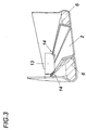
- the invention is characterized in that the cable 6 is connected at least partially non-positively in the further forming 3 or here in the final forming of the sheet 1 with the metal sheet 1, which in particular the Fig. 3 can be removed.
- Fig. 2 shown is a drawn by the partially formed sheet metal carriage 1 10, which is guided along the sheet 1, the cable 6 inserts into the guide receptacle 8 and the guide receptacle 8 by its associated rollers 4 and 4 'further roll-profiled.
- This reshaping closes the guide receptacle 8 and thus generates an undercut 11 holding the cable 6 in a force-fitting manner, which undercut 11 is, for example, the right-hand drawing of FIG FIG. 1 can be seen.
- this deformation also gives the outer and inner region of the sheet the desired final shape, as compared in comparison between sheet 1 and closed hollow section 2 Fig. 1 can be seen.
- the carriage 10 is assigned a plurality of further rollers 5, 5 '.
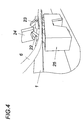
- a non-positive bond is shown in which from the sheet 1, a strip 22 is punched by means of a cutting tool 23.
- This strip 22 is bent over the cable 6 by means of a forming tool 24 located downstream of the cutting tool 23 in cooperation with a carriage 25.
- a frictional attachment of the cable 6 is shown on the plate 1 via brackets.
- the brackets 15 are riveted to the plate 1, plugged or otherwise connected to the plate 1.
- a double-sided adhesive strip 16 is applied, which forms an adhesive layer 17 and so the cable 6 attached to the sheet metal 1.
- Fig. 7 It is shown how the sheet 1 can be provided with a cable 6, which has a relation to the length of the sheet 1 increased cable length.
- the cable 6 is laid loop-shaped, so that cable loops 18 form in the cavity 7 of the hollow section 2. Especially in the region of an edge of the cut 19, this ensures that the cable 6 positively and / or materially connected cable 6 can be sufficiently pulled out of the hollow section 2 in order to connect this electrically.
- the cable loops 18 are held by pins 20 in the hollow profile 2, wherein the outer pins 20 have a predetermined breaking point 21. Thereby, a weakening of the non-positive or cohesive connection of the cable 6 can be ensured with the sheet 1 to facilitate removal of the cable 6.
- FIG. 8 an open hollow profile 26 with a plurality of chambers 27, 28 is shown. This hollow section 26 receives three cables 6 in its chamber 28. For non-positive connection of the cable 6 with the plate 1, an undercut 11 is formed in the plate 1.
Landscapes
- Engineering & Computer Science (AREA)
- Architecture (AREA)
- Civil Engineering (AREA)
- Structural Engineering (AREA)
- Manufacturing & Machinery (AREA)
- Installation Of Indoor Wiring (AREA)
- Wire Processing (AREA)
- Details Of Indoor Wiring (AREA)
- Shaping Metal By Deep-Drawing, Or The Like (AREA)
- Pressure Welding/Diffusion-Bonding (AREA)
Description
- Die Erfindung betrifft ein Verfahren zur Herstellung eines Strukturbauteils, insbesondere für ein Fahrzeug, bei dem ein Blech zu einem offenen oder geschlossenen und insbesondere mehrkammerigen Hohlprofil umgeformt und mit mindestens einem elektrischen Kabel versehen wird, das es wenigstens bereichsweise aufnimmt.
- Um ein Hohlprofil mit einem Kabel zu versehen, ist es bekannt, dieses in den Hohlraum des fertig profilierten Hohlprofils einzuziehen. Nachteilig bedarf es für diese Vorgehensweise einer erhöhten Verfahrensdauer, sowie auch einen erheblichen Herstellungsaufwand.
- Verschiedenste Umformverfahren zur Herstellung eines Hohlprofils aus einem Blech sind bekannt. Unter anderem auch ein Spaltprofilieren, bei dem Hohlprofile mit mehreren Kammern erzeugt werden. Meist ist auch mindestens eine dieser Kammern zur Aufnahme des Kabels vorgesehen.
-
WO 2012/010907 offenbart ein Verfahren nach dem Oberbegriff des Anspruchs 1. - Außerdem sind aus dem Stand der Technik Verfahren zur Herstellung von Kabeln mit einer Stahlhülle bekannt (
DE3527714C2 ). Dabei werden zwei Bleche zu je einem U-Profil rollprofiliert, ein Kabel zwischen den beiden fertigen U-Profilen eingelegt und anschließend die beiden U-Profile zu einer Stahlhülle zusammengeschweißt. Zwar kann durch das Einlegen des Kabels vor dem Verschweißen der U-Profile das Versehen des Blechs mit einem Kabel erleichtert werden, durch einen parallelen Umformschritt von zwei Blechen sowie deren anschließenden Verschweißung wird das Verfahren jedoch verhältnismäßig aufwändig - insbesondere in Hinblick auf die aufeinander abzustimmenden Stoßkanten der Rollprofile, um ein anschließendes Verschweißen zu ermöglichen. Daher sind auch hier eine erhöhte Verfahrensdauer, sowie ein hoher Herstellungsaufwand zu erwarten. - Es ist daher die Aufgabe der Erfindung, ausgehend vom eingangs geschilderten Stand der Technik, ein Verfahren zur Herstellung eines Hohlprofils mit einem in seinem Hohlraum vorgesehenen elektrischen Kabel zu vereinfachen.
- Die Erfindung löst die gestellte Aufgabe dadurch, dass das Blech bei seinem Umformen oder zwischen zwei seiner Umformungsschritte mit dem Kabel versehen und mit diesem Kabel zumindest bereichsweise kraft- oder stoffschlüssig verbunden wird, wobei das Blech mit einem Kabel versehen wird, das gegenüber der Länge des Blechs eine erhöhte Kabellänge aufweist.
- Wird das Blech bei seinem Umformen oder zwischen zwei seiner Umformungsschritte mit dem Kabel versehen und mit diesem Kabel zumindest bereichsweise kraft- oder stoffschlüssig verbunden, kann sich auf vorteilhafte Weise ein nachtägliches und meist aufwändiges Einziehen eines Kabels in das Hohlprofil erübrigen. Das höchstens teilweise umgeformte Blech kann nämlich mit seinem anhaftenden Kabel gemeinsam und somit auch verfahrenssicher zu seiner Endform weiter umgeformt werden, wodurch selbst bei komplexer Formgebung einfache Verfahrensverhältnisse hinsichtlich der Handhabung eines Kabels gewährleistet bleiben können. Hinzu kommt, dass mit der weiteren Formgebung des Blechs auch keine Abstimmung gegenüber anderen Profilteilen erfolgen muss, um damit einen Hohlraum zur Führung des Kabels zu erzeugen, womit das Verfahren auch äußerst reproduzierbar komplexe geschlossene oder offene Hohlprofile schaffen kann. Das erfindungsgemäß am umzuformenden bzw. weiter umzuformenden Blech befestigte Kabel kann daher zu einer erheblichen Handhabungsvereinfachung im Verfahren beitragen. Auf diese Weise kann erreicht werden, ein offenes oder geschlossenes Hohlprofil mit einem elektrischen Kabel in seinem Hohlraum effizient und kostengünstig herzustellen. Eventuelle - etwa bei seinem Verlegen - auftretende Zugbelastungen auf das Kabel können vermieden werden, indem das Blech mit einem Kabel versehen wird, das gegenüber der Länge des Blechs eine erhöhte Kabellänge aufweist. Dadurch kann sich auch ein Ablängen des Hohlprofils vereinfachen. Die zusätzliche Kabellänge im Hohlprofil kann die Möglichkeit eines Ablängens an jeglicher Stelle des Hohlprofils eröffnen - und ein einfaches Anschließen des aufgenommenen Kabels zulassen.
- Im Allgemeinen wird erwähnt, dass die kraft- oder stoffschlüssige Verbindung im Wesentlichen verhindern soll, dass das Kabel bei einer Handhabung des Hohlprofils aus dem Hohlprofil selbstständig herausfällt bzw. -rutscht. Beispielsweise ist vorstellbar, diesen Effekt der kraftschlüssigen Verbindung dadurch zu erreichen, dass das Kabel von dem vorprofilierten Blech eng geführt wird, um so eine ausreichende Haftreibung zwischen Kabel oder Kabeln und Blech sicherzustellen. Außerdem wird festgehalten, dass ein elektrisches Kabel mindestens einen elektrischen Leiter aufweist, der mit einer elektrisch isolierenden Umhüllung umgeben sein kann. Außerdem werden elektrisches Kabel und elektrische Leitung synonym verwendet.
- Im Allgemeinen wird erwähnt, dass sich das erfindungsgemäße Verfahren besonders bei einer Herstellung eines Hohlprofils auszeichnen kann, das als Strukturbauteil, beispielsweise für ein Fahrzeug, verwendet wird.
- Eine ausreichend feste Verbindung zwischen Blech und Kabel kann auf kostengünstige Weise hergestellt werden, wenn wenigstens eine Klammer am Blech befestigt wird, die das Kabel mit dem Blech kraftschlüssig verbindet.
- Alternativ oder auch zusätzlich zur Klammer kann zwischen Kabel und Blech mindestens bereichsweise eine Klebeschicht vorgesehen sein. Solch eine Klebeschicht kann außerdem den Vorteil bieten, dass komplexe Umformverfahren am Blech vorgenommen werden können, ohne dabei ein Lösen des Kabels vom Blech befürchten zu müssen. Dadurch kann die Gefahr von Beschädigungen am Kabel praktisch ausgeschlossen werden, was wiederum für eine erhöhte Reproduzierbarkeit des Verfahrens sorgen kann.
- Ein einfach durchzuführendes und zu steuerndes Verfahren kann sich ergeben, wenn das Blech zu einem Hohlprofil profiliert wird. Dies kann durch Spalt- und/oder Roll- bzw. Walzprofilieren erfolgen. Insbesondere kann sich Rollprofilieren auszeichnen, um für ein kostengünstig herstellbares Hohlprofil mit einem aufgenommenen Kabel zusorgen.
- Eine vereinfachte Handhabung im Zuge des Versehen des Blechs mit einem Kabel kann sich ergeben, wenn in einem Umformschritt mindestens eine entlang der Längsseite des Blechs verlaufende Führungsaufnahme erzeugt wird, die mit dem Kabel versehen wird. Die Führungsaufnahme kann nämlich sowohl als Einlegehilfe, als auch zur exakten Ausrichtung des Kabels genutzt werden. Insbesondere können durch diese exakte Positionierung des Kabels am Blech Beschädigung im Zuge des Umformens, die insbesondere im Zuge der Herstellung komplexer Hohlprofile bzw. Hohlprofilformen auftreten können, vermieden werden. Ein sicheres und reproduzierbares Verfahren kann so ermöglicht werden.
- Vorteilhaft kann das Umformen des Blechs gleichzeitig auch dazu genutzt werden, das Kabel am Blech kraftschlüssig zu verbinden. Hierfür ist das Blech gegenüber dem Kabel lediglich entsprechend umzuformen, beispielsweise indem das Blech am Kabel eng anliegt und damit einen erhöhten Reibschluss ausbildet, womit das Kabel im Hohlprofil gegenüber einem unerwünschten Ausziehen standfest gehalten wird.
- Diese kraftschlüssige Verbindung zwischen Kabel und Blech kann ermöglicht werden, indem eine das Kabel kraftschlüssig haltende Hinterschneidung in das Blech profiliert wird. Solch eine Hinterschneidung kann beispielsweise durch ein Umbiegen eines Stegs am Blech hergestellt werden. Ein einfaches Verfahren kann sich so ergeben.
- Alternativ dazu bzw. auch zusätzlich dazu kann die kraftschlüssige Verbindung ausgebildet bzw. in ihrer Standfestigkeit verbessert werden, wenn das Blech mit dem Kabel punktuell verquetscht wird.
- Wird ein Schlitten entlang des Blechs geführt wird, mit dem das Blech zum kraftschlüssigen Verbinden mit dem Kabel umgeformt wird, kann der Verfahrensablauf beschleunigt und in seiner Genauigkeit verbessert werden.
- Das Verfahren kann weiter vereinfacht werden, indem der Schlitten das Kabel zum Blech führt und dieses damit versieht.
- Wird das Kabel wenigstens bereichsweise schlingenförmig verlegt, kann für eine ausreichende Reservelänge des im Hohlprofil verlegten Kabels gesorgt werden. Insbesondere kann sich eine Schlinge als vorteilhaft im Bereich der Ablängung des Hohlprofils und/oder elektrischen Abzweigung am Hohlprofil auszeichnen, etwa um das Kabel dem Hohlprofil entnehmen zu können.
- Ein Ausziehen des Kabels kann erleichtert werden, indem beim schlingenförmigen Verlegen des Kabels die kraft- oder stoffschlüssige Verbindung des Kabels mit dem Blech in diesem Bereich zur Erzeugung einer Sollbruchstelle geschwächt wird. Damit können bereits leichte Zugkräfte auf das Kabel ausreichen, dieses dem Hohlprofil zu dessen elektrischen Anschluss zu entnehmen. Die Handhabungfreundlichkeit eines Hohlprofils kann dadurch erheblich erhöht werden.
- Ein geschlossenes Hohlprofil kann auf einfache Weise erzeugt werden, wenn das Hohlprofil an seinen längsseitigen Profilenden stoffschlüssig verbunden wird. Unterschiedliche Schweißverfahren sind hierfür vorstellbar.
- In den Zeichnungen ist der Erfindungsgegenstand beispielsweise anhand mehrerer Ausführungsbeispiele dargestellt. Es zeigen
- Fig. 1
- zwei Verfahrensschritte zum Herstellen eines Hohlprofils mit einem Kabel in seinem Hohlraum,
- Fig. 2
- eine Detailansicht zum Verfahrensschritt nach
Fig. 1 , bei dem das Blech mit einem Kabel bei gleichzeitiger Umformung des Blechs zum Hohlprofil versehen wird, - Fig. 3
- eine Detailansicht zum Verfahrensschritt, bei dem das Blech in einer alternativen Ausführungsform mit dem Kabel verquetscht wird,
- Fig. 4
- eine dritte Ausführung des Verfahrens,
- Fig. 5
- eine vierte Ausführung des Verfahrens, bei der das Kabel über Klammern mit dem Blech kraftschlüssig verbunden ist,
- Fig. 6
- eine fünfte Ausführung des Verfahrens mit einer stoffschlüssigen Verbindung zwischen Blech und Kabel,
- Fig. 7
- eine Darstellung zu einer schlingenförmigen Verlegung des Kabels,
- Fig. 8
- eine sechste Ausführung des Verfahrens mit einer kraftschlüssigen Verbindung zwischen Blech und Kabel.
- Nach
Fig. 1 ist ein bereits teilweise umgeformtes Blech 1 in Stirnansicht dargestellt, das zu einem Hohlprofil 2 mit Hilfe einer Rollprofilierung 3 endumgeformt wird. Für dieses kontinuierliche Biegeverfahren belasten Walzen 4, 5 das teilumgeformte Blech 1, um dieses auf den gewünschten Endquerschnitt, gemäß Hohlprofil 2, zu bringen. Das Hohlprofil 2 weist zudem ein Kabel 6 auf, das im Hohlraum 7 des Hohlprofils verläuft bzw. vom Hohlprofil 2 aufgenommen wird. Um nun ein nachträgliches Einziehen in das fertige Hohlprofil 2 eines Kabels 6 zu vermeiden, wird das Blech 1 bereits vor seinem Endumformen - also zwischen zwei Umformschritten, dem Teilumformen und Endumformen-, mit dem Kabel 6 versehen, wie dies inFig. 1 erkannt werden kann. Am Blech 1 wurde bereits in einem Umformschritt zuvor eine entlang seiner Längsseite verlaufende Führungsaufnahme 8 eingeformt, um dem Kabel 6 eine Kammer 9 im Hohlraum 7 des Endprofils 2 zur Verfügung zu stellen. Diese Kammer 9 kann insbesondere auch bei der weiteren Verwendung des Holprofils 2 von Vorteil sein, um dadurch das Kabel 6 zu schützen. Das noch nicht endumgeformte Blech 1 kann nun mit dem Kabel 6 vergleichsweise einfach versehen werden, weil seine Endabmessungen gemäß dem zu erzeugenden Hohlprofil 2 noch nicht erreicht sind. Besonders aber zeichnet sich die Erfindung dadurch aus, dass das Kabel 6 beim weiteren Umformen 3 bzw. hier beim Endumformen des Blechs 1 mit dem Blech 1 zumindest bereichsweise kraftschlüssig verbunden wird, was insbesondere derFig. 3 entnommen werden kann. - In
Fig. 2 ist ein durch das teilumgeformte Blech 1 gezogener Schlitten 10 dargestellt, der entlang des Blechs 1 geführt, das Kabel 6 in die Führungsaufnahme 8 einlegt und die Führungsaufnahme 8 durch ihr zugeordnete Walzen 4 und 4' weiter walzprofiliert. Dieses Umformen schließt die Führungsaufnahme 8 und erzeugt damit eine das Kabel 6 kraftschlüssig haltende Hinterschneidung 11, welche Hinterschneidung 11 beispielsweise der rechten Zeichnung derFigur 1 zu entnehmen ist. Zusätzlich gibt dieses Umformen auch dem Außen- und Innenbereich des Blechs die gewünschte Endform, wie im Vergleich zwischen Blech 1 und geschlossenem Hohlprofil 2 nachFig. 1 zu erkennen ist. Hierfür sind dem Schlitten 10 mehrere weitere Walzen 5, 5' zugeordnet. - Zusätzlich oder auch alternativ zum nach
Fig. 2 dargestellten Schlitten 10 wird nachFig. 3 gezeigt, dass das Blech auch mit einem Quetschwerkzeug 13 umgeformt werden kann. Mit Hilfe dieses Quetschwerkzeugs 13 wird nämlich das Blech 1 mit dem Kabel 6 verquetscht, wie dies an den Quetschpunkten 14 zu sehen ist. Diese Quetschpunkte 14 reichen aus, um für eine kraftschlüssige Verbindung zwischen Blech 1 und Kabel 6 zu sorgen. - Nach
Fig. 4 wird ein kraftschlüssiger Verbund gezeigt, bei dem aus dem Blech 1 ein Streifen 22 mit Hilfe eines Schneidwerkzeugs 23 ausgestanzt wird. Dieser Streifen 22 wird mit Hilfe eines dem Schneidwerkzeug 23 nachgeordneten Umformwerkzeugs 24 in Zusammenspiel mit einem Schlitten 25 über das Kabel 6 gebogen. - Nach
Fig. 5 wird eine kraftschlüssige Befestigung des Kabels 6 am Blech 1 über Klammern dargestellt. Die Klammern 15 sind an das Blech 1 genietet, gesteckt oder anderwärtig mit dem Blech 1 verbunden. - Ebenso denkbar ist eine stoffschlüssige Verbindung zwischen Blech 1 und Kabel 6 zur Fixierung des Kabels am Blech 1, was nach
Fig. 6 näher dargestellt wird. Auf das Blech 1 ist ein doppelseitig klebender Klebestreifen 16 aufgebracht, der eine Klebeschicht 17 ausbildet und so das Kabel 6 am Blech 1 befestigt. - Nach
Fig. 7 ist dargestellt, wie das Blech 1 mit einem Kabel 6 versehen werden kann, das eine gegenüber der Länge des Blechs 1 erhöhten Kabellänge aufweist. - Hierfür wird das Kabel 6 schlingenförmig verlegt, so dass sich Kabelschlingen 18 im Hohlraum 7 des Hohlprofils 2 ausbilden. Gerade im Bereich einer Kante der Ablängung 19 sorgt dies dafür, dass das mit dem Blech 1 kraft- und/oder stoffschlüssig verbundene Kabel 6 ausreichend aus dem Hohlprofil 2 gezogen werden kann, um dieses elektrisch anzuschließen.
- Die Kabelschlingen 18 werden über Stifte 20 im Hohlprofil 2 gehalten, wobei die äußeren Stifte 20 eine Sollbruchstelle 21 aufweisen. Dadurch kann eine Schwächung der kraft- oder stoffschlüssigen Verbindung des Kabels 6 mit dem Blech 1 sichergestellt werden, um ein Ausziehen des Kabels 6 zu erleichtern.
- In
Fig. 8 wird ein offenes Hohlprofil 26 mit mehreren Kammern 27, 28 dargestellt. Dieses Hohlprofil 26 nimmt drei Kabel 6 in seiner Kammer 28 auf. Zum kraftschlüssigen Verbinden der Kabel 6 mit dem Blech 1 ist in das Blech 1 eine Hinterschneidung 11 eingeformt.
Claims (14)
- Verfahren zur Herstellung eines Strukturbauteils, insbesondere für ein Fahrzeug, bei dem ein Blech (1) zu einem offenen oder geschlossenen und insbesondere mehrkammerigen Hohlprofil (2) umgeformt und mit mindestens einem elektrischen Kabel (6) versehen wird, das es wenigstens bereichsweise aufnimmt, dadurch gekennzeichnet, dass das Blech (1) bei seinem Umformen oder zwischen zwei seiner Umformungsschritte mit dem Kabel (6) versehen und mit diesem Kabel (6) zumindest bereichsweise kraft- oder stoffschlüssig verbunden wird, wobei das Blech (1) mit einem Kabel (6) versehen wird, das gegenüber der Länge des Blechs (1) eine erhöhte Kabellänge aufweist.
- Verfahren nach Anspruch 1, dadurch gekennzeichnet, dass wenigstens eine Klammer (15) am Blech (1) befestigt wird, die das Kabel (6) mit dem Blech (1) kraftschlüssig verbindet.
- Verfahren nach Anspruch 1 oder 2, dadurch gekennzeichnet, dass zwischen Kabel (6) und Blech (1) mindestens bereichsweise eine Klebeschicht (17) vorgesehen ist.
- Verfahren nach Anspruch 1, 2 oder 3, dadurch gekennzeichnet, dass das Blech (1) zu einem Hohlprofil (2) profiliert, insbesondere spalt- und/oder roll- bzw. walzprofiliert, wird.
- Verfahren nach einem der Ansprüche 1 bis 4, dadurch gekennzeichnet, dass in einem Umformschritt mindestens eine entlang der Längsseite des Blechs (1) verlaufende Führungsaufnahme (8) erzeugt wird, die mit dem Kabel (6) versehen wird.
- Verfahren nach einem der Ansprüche 1 bis 5, dadurch gekennzeichnet, dass das Blech (1) gegenüber dem Kabel (6) derart umgeformt wird, dass sich zwischen Kabel (6) und Blech (1) eine kraftschlüssige Verbindung ausbildet.
- Verfahren nach Anspruch 6, dadurch gekennzeichnet, dass eine das Kabel (6) kraftschlüssig haltende Hinterschneidung (11) in das Blech (1) profiliert wird.
- Verfahren nach Anspruch 6 oder 7, dadurch gekennzeichnet, dass das Blech (1) mit dem Kabel (6) punktuell verquetscht wird.
- Verfahren nach Anspruch 6, 7 oder 8, dadurch gekennzeichnet, dass ein Schlitten entlang des Blechs (1) geführt wird, mit dem das Blech (1) zum kraftschlüssigen Verbinden mit dem Kabel (6) umgeformt wird.
- Verfahren nach einem der Ansprüche 1 bis 9, dadurch gekennzeichnet, dass der Schlitten das Kabel (6) zum Blech (1) führt und dieses damit versieht.
- Verfahren nach Anspruch 10, dadurch gekennzeichnet, dass das Kabel (6) wenigstens bereichsweise schlingenförmig, insbesondere im Bereich einer Ablängung (19) des Hohlprofils (2) und/oder elektrischen Abzweigung am Hohlprofil (2), verlegt wird.
- Verfahren nach Anspruch 11, dadurch gekennzeichnet, dass beim schlingenförmigen Verlegen des Kabels (6) die kraft- oder stoffschlüssige Verbindung des Kabels (6) mit dem Blech (1) in diesem Bereich zur Erzeugung einer Sollbruchstelle (21) geschwächt wird.
- Verfahren nach Anspruch 11 oder 12, dadurch gekennzeichnet, dass beim schlingenförmigen Verlegen des Kabels (6) diese Kabelbereiche wenigstens teilweise lösbar gegeneinander fixiert werden.
- Verfahren nach einem der Ansprüche 1 bis 13, dadurch gekennzeichnet, dass das Hohlprofil (2) an seinen längsseitigen Profilenden stoffschlüssig verbunden wird, um ein geschlossenes Hohlprofil (2) zu erzeugen.
Priority Applications (6)
| Application Number | Priority Date | Filing Date | Title |
|---|---|---|---|
| DK12174391.8T DK2680381T3 (en) | 2012-06-29 | 2012-06-29 | Process for producing an open or closed and especially multi-chamber hollow profile |
| EP12174391.8A EP2680381B1 (de) | 2012-06-29 | 2012-06-29 | Verfahren zur Herstellung eines offenen oder geschlossenen und insbesondere mehrkammerigen Hohlprofils |
| ES12174391.8T ES2552213T3 (es) | 2012-06-29 | 2012-06-29 | Procedimiento para producir un perfil hueco abierto o cerrado, y en particular con varias cámaras |
| PCT/EP2013/063875 WO2014001581A2 (de) | 2012-06-29 | 2013-07-01 | Verfahren zur herstellung eines strukturbauteils |
| RU2015102803A RU2015102803A (ru) | 2012-06-29 | 2013-07-01 | Способ изготовления структурной детали |
| US14/411,606 US20150194243A1 (en) | 2012-06-29 | 2013-07-01 | Method for producing a structural component |
Applications Claiming Priority (1)
| Application Number | Priority Date | Filing Date | Title |
|---|---|---|---|
| EP12174391.8A EP2680381B1 (de) | 2012-06-29 | 2012-06-29 | Verfahren zur Herstellung eines offenen oder geschlossenen und insbesondere mehrkammerigen Hohlprofils |
Publications (2)
| Publication Number | Publication Date |
|---|---|
| EP2680381A1 EP2680381A1 (de) | 2014-01-01 |
| EP2680381B1 true EP2680381B1 (de) | 2015-08-12 |
Family
ID=48874999
Family Applications (1)
| Application Number | Title | Priority Date | Filing Date |
|---|---|---|---|
| EP12174391.8A Not-in-force EP2680381B1 (de) | 2012-06-29 | 2012-06-29 | Verfahren zur Herstellung eines offenen oder geschlossenen und insbesondere mehrkammerigen Hohlprofils |
Country Status (6)
| Country | Link |
|---|---|
| US (1) | US20150194243A1 (de) |
| EP (1) | EP2680381B1 (de) |
| DK (1) | DK2680381T3 (de) |
| ES (1) | ES2552213T3 (de) |
| RU (1) | RU2015102803A (de) |
| WO (1) | WO2014001581A2 (de) |
Family Cites Families (5)
| Publication number | Priority date | Publication date | Assignee | Title |
|---|---|---|---|---|
| US3430337A (en) * | 1967-02-28 | 1969-03-04 | William D Kelly | Method of making an armored cable |
| US3745230A (en) * | 1972-01-12 | 1973-07-10 | W Kelly | Metal sheathed electrical wire cable |
| DE3527714A1 (de) | 1985-08-02 | 1987-02-12 | Kernforschungsz Karlsruhe | Verfahren zur herstellung einer metallischen umhuellung fuer ein elektrisches kabel mit einer aussen eckigen und innen runden kontur |
| US8013249B2 (en) * | 2006-11-24 | 2011-09-06 | Autonetworks Technologies, Ltd. | Shield conductor and shield conductor manufacturing method |
| GB201012319D0 (en) * | 2010-07-22 | 2010-09-08 | Artificial Lift Co Ltd | Cables for downhole use |
-
2012
- 2012-06-29 EP EP12174391.8A patent/EP2680381B1/de not_active Not-in-force
- 2012-06-29 ES ES12174391.8T patent/ES2552213T3/es active Active
- 2012-06-29 DK DK12174391.8T patent/DK2680381T3/en active
-
2013
- 2013-07-01 WO PCT/EP2013/063875 patent/WO2014001581A2/de not_active Ceased
- 2013-07-01 US US14/411,606 patent/US20150194243A1/en not_active Abandoned
- 2013-07-01 RU RU2015102803A patent/RU2015102803A/ru not_active Application Discontinuation
Also Published As
| Publication number | Publication date |
|---|---|
| RU2015102803A (ru) | 2016-08-20 |
| WO2014001581A2 (de) | 2014-01-03 |
| DK2680381T3 (en) | 2015-11-23 |
| ES2552213T3 (es) | 2015-11-26 |
| WO2014001581A3 (de) | 2014-08-07 |
| EP2680381A1 (de) | 2014-01-01 |
| US20150194243A1 (en) | 2015-07-09 |
Similar Documents
| Publication | Publication Date | Title |
|---|---|---|
| DE4205574C2 (de) | Kanalkörper und Verfahren zum Verlegen eines Kabels in diesem | |
| EP2786447A1 (de) | Anschlussklemme mit einer stegförmigen leiterführung | |
| EP2313216B1 (de) | Verfahren zur herstellung eines kaltgewalzten profils mit mindestens einer verdickten profilkante | |
| DE2359367B2 (de) | Verfahren zur Herstellung von Verstärkungsfasern für ein vergießbares Material | |
| EP2362508B1 (de) | Verfahren zum ummanteln eines elektrischen Leiters mit einem elastischen Dichtungselement | |
| WO2009109586A1 (de) | Dachfensterrollo mit spanneinrichtung | |
| DE2239769A1 (de) | Verbinder fuer elektrokabel | |
| EP2965830B1 (de) | Verfahren zum herstellen eines torsionsprofils aus einem rohrförmigen hohlprofil | |
| DE102011075463A1 (de) | Mauer mit integrierter Schalung, ausgestattet mit mindestens einer Hebevorrichtung und Herstellungsverfahren für eine solche Mauer | |
| EP2446980B1 (de) | Gerüstrohr und Verfahren zur Bearbeitung von Rohrenden | |
| WO2009059731A1 (de) | Metallprofil | |
| EP2680381A1 (de) | Verfahren zur Herstellung eines offenen oder geschlossenen und insbesondere mehrkammerigen Hohlprofils | |
| EP2996826B1 (de) | Verfahren und einrichtung zum trennen von hohlkammerprofilen | |
| EP4054898A1 (de) | Kraftfahrzeugenergieleitung sowie ein verfahren zum biegen einer kraftfahrzeugenergieleitung | |
| EP1156258A1 (de) | Federbandschellenblock | |
| DE102007018915B4 (de) | Stützwendel mit mechanischer Verriegelung und Verfahren zu deren Herstellung | |
| DE2614023A1 (de) | Metallischer rahmen aus einem rohrprofil und verfahren zum biegen des rohrprofils | |
| EP2799783B1 (de) | Halter zum Fixieren einer Leitung, insbesondere eines Rohres, sowie entsprechende Verbindungsanordnung | |
| DE102013005295A1 (de) | Verfahren und Werkzeug zum Verbinden eines Blechbauteils mit einem weiteren Bauteil | |
| EP2243567A1 (de) | Vorrichtung zur Herstellung von quer zu ihrer Längsrichtung gewellten Rohren | |
| DE202021102161U1 (de) | Aus Metall hergestellte Kabelrinnenkomponente, insbesondere Kabelrinne oder Kabelrinnendeckel | |
| EP2677603B1 (de) | Seil- und Litzenverbinder für elektrische Weidezäune | |
| DE102014117949A1 (de) | Kontaktmodul mit Klemmeinrichtung | |
| DE3309348A1 (de) | Verfahren und vorrichtung zur herstellung eines kabelbaumes | |
| DE102014103784A1 (de) | Verfahren und Vorrichtung zum Ausschäumen von Hohlprofilen |
Legal Events
| Date | Code | Title | Description |
|---|---|---|---|
| PUAI | Public reference made under article 153(3) epc to a published international application that has entered the european phase |
Free format text: ORIGINAL CODE: 0009012 |
|
| AK | Designated contracting states |
Kind code of ref document: A1 Designated state(s): AL AT BE BG CH CY CZ DE DK EE ES FI FR GB GR HR HU IE IS IT LI LT LU LV MC MK MT NL NO PL PT RO RS SE SI SK SM TR |
|
| AX | Request for extension of the european patent |
Extension state: BA ME |
|
| 17P | Request for examination filed |
Effective date: 20131230 |
|
| RBV | Designated contracting states (corrected) |
Designated state(s): AL AT BE BG CH CY CZ DE DK EE ES FI FR GB GR HR HU IE IS IT LI LT LU LV MC MK MT NL NO PL PT RO RS SE SI SK SM TR |
|
| GRAP | Despatch of communication of intention to grant a patent |
Free format text: ORIGINAL CODE: EPIDOSNIGR1 |
|
| INTG | Intention to grant announced |
Effective date: 20150206 |
|
| GRAS | Grant fee paid |
Free format text: ORIGINAL CODE: EPIDOSNIGR3 |
|
| GRAA | (expected) grant |
Free format text: ORIGINAL CODE: 0009210 |
|
| AK | Designated contracting states |
Kind code of ref document: B1 Designated state(s): AL AT BE BG CH CY CZ DE DK EE ES FI FR GB GR HR HU IE IS IT LI LT LU LV MC MK MT NL NO PL PT RO RS SE SI SK SM TR |
|
| REG | Reference to a national code |
Ref country code: GB Ref legal event code: FG4D Free format text: NOT ENGLISH |
|
| REG | Reference to a national code |
Ref country code: CH Ref legal event code: EP |
|
| REG | Reference to a national code |
Ref country code: AT Ref legal event code: REF Ref document number: 742887 Country of ref document: AT Kind code of ref document: T Effective date: 20150815 |
|
| REG | Reference to a national code |
Ref country code: IE Ref legal event code: FG4D Free format text: LANGUAGE OF EP DOCUMENT: GERMAN |
|
| REG | Reference to a national code |
Ref country code: DE Ref legal event code: R096 Ref document number: 502012004079 Country of ref document: DE |
|
| REG | Reference to a national code |
Ref country code: DK Ref legal event code: T3 Effective date: 20151116 |
|
| REG | Reference to a national code |
Ref country code: ES Ref legal event code: FG2A Ref document number: 2552213 Country of ref document: ES Kind code of ref document: T3 Effective date: 20151126 |
|
| REG | Reference to a national code |
Ref country code: CH Ref legal event code: NV Representative=s name: ISLER AND PEDRAZZINI AG, CH |
|
| REG | Reference to a national code |
Ref country code: LT Ref legal event code: MG4D |
|
| REG | Reference to a national code |
Ref country code: NL Ref legal event code: FP |
|
| PG25 | Lapsed in a contracting state [announced via postgrant information from national office to epo] |
Ref country code: LV Free format text: LAPSE BECAUSE OF FAILURE TO SUBMIT A TRANSLATION OF THE DESCRIPTION OR TO PAY THE FEE WITHIN THE PRESCRIBED TIME-LIMIT Effective date: 20150812 Ref country code: NO Free format text: LAPSE BECAUSE OF FAILURE TO SUBMIT A TRANSLATION OF THE DESCRIPTION OR TO PAY THE FEE WITHIN THE PRESCRIBED TIME-LIMIT Effective date: 20151112 Ref country code: FI Free format text: LAPSE BECAUSE OF FAILURE TO SUBMIT A TRANSLATION OF THE DESCRIPTION OR TO PAY THE FEE WITHIN THE PRESCRIBED TIME-LIMIT Effective date: 20150812 Ref country code: GR Free format text: LAPSE BECAUSE OF FAILURE TO SUBMIT A TRANSLATION OF THE DESCRIPTION OR TO PAY THE FEE WITHIN THE PRESCRIBED TIME-LIMIT Effective date: 20151113 Ref country code: LT Free format text: LAPSE BECAUSE OF FAILURE TO SUBMIT A TRANSLATION OF THE DESCRIPTION OR TO PAY THE FEE WITHIN THE PRESCRIBED TIME-LIMIT Effective date: 20150812 |
|
| PG25 | Lapsed in a contracting state [announced via postgrant information from national office to epo] |
Ref country code: PT Free format text: LAPSE BECAUSE OF FAILURE TO SUBMIT A TRANSLATION OF THE DESCRIPTION OR TO PAY THE FEE WITHIN THE PRESCRIBED TIME-LIMIT Effective date: 20151214 Ref country code: PL Free format text: LAPSE BECAUSE OF FAILURE TO SUBMIT A TRANSLATION OF THE DESCRIPTION OR TO PAY THE FEE WITHIN THE PRESCRIBED TIME-LIMIT Effective date: 20150812 Ref country code: IS Free format text: LAPSE BECAUSE OF FAILURE TO SUBMIT A TRANSLATION OF THE DESCRIPTION OR TO PAY THE FEE WITHIN THE PRESCRIBED TIME-LIMIT Effective date: 20151212 Ref country code: SE Free format text: LAPSE BECAUSE OF FAILURE TO SUBMIT A TRANSLATION OF THE DESCRIPTION OR TO PAY THE FEE WITHIN THE PRESCRIBED TIME-LIMIT Effective date: 20150812 Ref country code: HR Free format text: LAPSE BECAUSE OF FAILURE TO SUBMIT A TRANSLATION OF THE DESCRIPTION OR TO PAY THE FEE WITHIN THE PRESCRIBED TIME-LIMIT Effective date: 20150812 Ref country code: RS Free format text: LAPSE BECAUSE OF FAILURE TO SUBMIT A TRANSLATION OF THE DESCRIPTION OR TO PAY THE FEE WITHIN THE PRESCRIBED TIME-LIMIT Effective date: 20150812 |
|
| REG | Reference to a national code |
Ref country code: SK Ref legal event code: T3 Ref document number: E 19720 Country of ref document: SK |
|
| PG25 | Lapsed in a contracting state [announced via postgrant information from national office to epo] |
Ref country code: EE Free format text: LAPSE BECAUSE OF FAILURE TO SUBMIT A TRANSLATION OF THE DESCRIPTION OR TO PAY THE FEE WITHIN THE PRESCRIBED TIME-LIMIT Effective date: 20150812 Ref country code: IT Free format text: LAPSE BECAUSE OF FAILURE TO SUBMIT A TRANSLATION OF THE DESCRIPTION OR TO PAY THE FEE WITHIN THE PRESCRIBED TIME-LIMIT Effective date: 20150812 |
|
| REG | Reference to a national code |
Ref country code: DE Ref legal event code: R097 Ref document number: 502012004079 Country of ref document: DE |
|
| PG25 | Lapsed in a contracting state [announced via postgrant information from national office to epo] |
Ref country code: RO Free format text: LAPSE BECAUSE OF FAILURE TO SUBMIT A TRANSLATION OF THE DESCRIPTION OR TO PAY THE FEE WITHIN THE PRESCRIBED TIME-LIMIT Effective date: 20150812 |
|
| PLBE | No opposition filed within time limit |
Free format text: ORIGINAL CODE: 0009261 |
|
| STAA | Information on the status of an ep patent application or granted ep patent |
Free format text: STATUS: NO OPPOSITION FILED WITHIN TIME LIMIT |
|
| 26N | No opposition filed |
Effective date: 20160513 |
|
| PG25 | Lapsed in a contracting state [announced via postgrant information from national office to epo] |
Ref country code: SI Free format text: LAPSE BECAUSE OF FAILURE TO SUBMIT A TRANSLATION OF THE DESCRIPTION OR TO PAY THE FEE WITHIN THE PRESCRIBED TIME-LIMIT Effective date: 20150812 |
|
| PG25 | Lapsed in a contracting state [announced via postgrant information from national office to epo] |
Ref country code: BE Free format text: LAPSE BECAUSE OF NON-PAYMENT OF DUE FEES Effective date: 20160630 |
|
| PG25 | Lapsed in a contracting state [announced via postgrant information from national office to epo] |
Ref country code: MC Free format text: LAPSE BECAUSE OF FAILURE TO SUBMIT A TRANSLATION OF THE DESCRIPTION OR TO PAY THE FEE WITHIN THE PRESCRIBED TIME-LIMIT Effective date: 20150812 |
|
| GBPC | Gb: european patent ceased through non-payment of renewal fee |
Effective date: 20160629 |
|
| REG | Reference to a national code |
Ref country code: IE Ref legal event code: MM4A |
|
| REG | Reference to a national code |
Ref country code: FR Ref legal event code: ST Effective date: 20170228 |
|
| PG25 | Lapsed in a contracting state [announced via postgrant information from national office to epo] |
Ref country code: FR Free format text: LAPSE BECAUSE OF NON-PAYMENT OF DUE FEES Effective date: 20160630 |
|
| PG25 | Lapsed in a contracting state [announced via postgrant information from national office to epo] |
Ref country code: GB Free format text: LAPSE BECAUSE OF NON-PAYMENT OF DUE FEES Effective date: 20160629 Ref country code: IE Free format text: LAPSE BECAUSE OF NON-PAYMENT OF DUE FEES Effective date: 20160629 |
|
| PGFP | Annual fee paid to national office [announced via postgrant information from national office to epo] |
Ref country code: SK Payment date: 20170626 Year of fee payment: 6 Ref country code: CZ Payment date: 20170626 Year of fee payment: 6 Ref country code: DK Payment date: 20170622 Year of fee payment: 6 |
|
| PGFP | Annual fee paid to national office [announced via postgrant information from national office to epo] |
Ref country code: NL Payment date: 20170628 Year of fee payment: 6 |
|
| PGFP | Annual fee paid to national office [announced via postgrant information from national office to epo] |
Ref country code: ES Payment date: 20170717 Year of fee payment: 6 |
|
| PGFP | Annual fee paid to national office [announced via postgrant information from national office to epo] |
Ref country code: CH Payment date: 20171124 Year of fee payment: 6 |
|
| PG25 | Lapsed in a contracting state [announced via postgrant information from national office to epo] |
Ref country code: HU Free format text: LAPSE BECAUSE OF FAILURE TO SUBMIT A TRANSLATION OF THE DESCRIPTION OR TO PAY THE FEE WITHIN THE PRESCRIBED TIME-LIMIT; INVALID AB INITIO Effective date: 20120629 Ref country code: SM Free format text: LAPSE BECAUSE OF FAILURE TO SUBMIT A TRANSLATION OF THE DESCRIPTION OR TO PAY THE FEE WITHIN THE PRESCRIBED TIME-LIMIT Effective date: 20150812 Ref country code: CY Free format text: LAPSE BECAUSE OF FAILURE TO SUBMIT A TRANSLATION OF THE DESCRIPTION OR TO PAY THE FEE WITHIN THE PRESCRIBED TIME-LIMIT Effective date: 20150812 |
|
| PG25 | Lapsed in a contracting state [announced via postgrant information from national office to epo] |
Ref country code: MK Free format text: LAPSE BECAUSE OF FAILURE TO SUBMIT A TRANSLATION OF THE DESCRIPTION OR TO PAY THE FEE WITHIN THE PRESCRIBED TIME-LIMIT Effective date: 20150812 Ref country code: LU Free format text: LAPSE BECAUSE OF NON-PAYMENT OF DUE FEES Effective date: 20160629 Ref country code: MT Free format text: LAPSE BECAUSE OF FAILURE TO SUBMIT A TRANSLATION OF THE DESCRIPTION OR TO PAY THE FEE WITHIN THE PRESCRIBED TIME-LIMIT Effective date: 20150812 Ref country code: TR Free format text: LAPSE BECAUSE OF FAILURE TO SUBMIT A TRANSLATION OF THE DESCRIPTION OR TO PAY THE FEE WITHIN THE PRESCRIBED TIME-LIMIT Effective date: 20150812 |
|
| PG25 | Lapsed in a contracting state [announced via postgrant information from national office to epo] |
Ref country code: BG Free format text: LAPSE BECAUSE OF FAILURE TO SUBMIT A TRANSLATION OF THE DESCRIPTION OR TO PAY THE FEE WITHIN THE PRESCRIBED TIME-LIMIT Effective date: 20150812 |
|
| PGFP | Annual fee paid to national office [announced via postgrant information from national office to epo] |
Ref country code: DE Payment date: 20180625 Year of fee payment: 7 |
|
| PGFP | Annual fee paid to national office [announced via postgrant information from national office to epo] |
Ref country code: AT Payment date: 20180626 Year of fee payment: 7 |
|
| PG25 | Lapsed in a contracting state [announced via postgrant information from national office to epo] |
Ref country code: AL Free format text: LAPSE BECAUSE OF FAILURE TO SUBMIT A TRANSLATION OF THE DESCRIPTION OR TO PAY THE FEE WITHIN THE PRESCRIBED TIME-LIMIT Effective date: 20150812 |
|
| REG | Reference to a national code |
Ref country code: DK Ref legal event code: EBP Effective date: 20180630 |
|
| PG25 | Lapsed in a contracting state [announced via postgrant information from national office to epo] |
Ref country code: CZ Free format text: LAPSE BECAUSE OF NON-PAYMENT OF DUE FEES Effective date: 20180629 |
|
| REG | Reference to a national code |
Ref country code: CH Ref legal event code: PL |
|
| REG | Reference to a national code |
Ref country code: NL Ref legal event code: MM Effective date: 20180701 |
|
| REG | Reference to a national code |
Ref country code: SK Ref legal event code: MM4A Ref document number: E 19720 Country of ref document: SK Effective date: 20180629 |
|
| PG25 | Lapsed in a contracting state [announced via postgrant information from national office to epo] |
Ref country code: NL Free format text: LAPSE BECAUSE OF NON-PAYMENT OF DUE FEES Effective date: 20180701 |
|
| PG25 | Lapsed in a contracting state [announced via postgrant information from national office to epo] |
Ref country code: LI Free format text: LAPSE BECAUSE OF NON-PAYMENT OF DUE FEES Effective date: 20180630 Ref country code: CH Free format text: LAPSE BECAUSE OF NON-PAYMENT OF DUE FEES Effective date: 20180630 |
|
| PG25 | Lapsed in a contracting state [announced via postgrant information from national office to epo] |
Ref country code: SK Free format text: LAPSE BECAUSE OF NON-PAYMENT OF DUE FEES Effective date: 20180629 |
|
| PG25 | Lapsed in a contracting state [announced via postgrant information from national office to epo] |
Ref country code: DK Free format text: LAPSE BECAUSE OF NON-PAYMENT OF DUE FEES Effective date: 20180630 |
|
| REG | Reference to a national code |
Ref country code: ES Ref legal event code: FD2A Effective date: 20190916 |
|
| PG25 | Lapsed in a contracting state [announced via postgrant information from national office to epo] |
Ref country code: ES Free format text: LAPSE BECAUSE OF NON-PAYMENT OF DUE FEES Effective date: 20180630 |
|
| REG | Reference to a national code |
Ref country code: DE Ref legal event code: R119 Ref document number: 502012004079 Country of ref document: DE |
|
| REG | Reference to a national code |
Ref country code: AT Ref legal event code: MM01 Ref document number: 742887 Country of ref document: AT Kind code of ref document: T Effective date: 20190629 |
|
| PG25 | Lapsed in a contracting state [announced via postgrant information from national office to epo] |
Ref country code: AT Free format text: LAPSE BECAUSE OF NON-PAYMENT OF DUE FEES Effective date: 20190629 Ref country code: DE Free format text: LAPSE BECAUSE OF NON-PAYMENT OF DUE FEES Effective date: 20200101 |