EP2680292A2 - Object detecting actuator and object detecting switch - Google Patents
Object detecting actuator and object detecting switch Download PDFInfo
- Publication number
- EP2680292A2 EP2680292A2 EP13173096.2A EP13173096A EP2680292A2 EP 2680292 A2 EP2680292 A2 EP 2680292A2 EP 13173096 A EP13173096 A EP 13173096A EP 2680292 A2 EP2680292 A2 EP 2680292A2
- Authority
- EP
- European Patent Office
- Prior art keywords
- roller
- stainless steel
- steel material
- actuator
- object detecting
- Prior art date
- Legal status (The legal status is an assumption and is not a legal conclusion. Google has not performed a legal analysis and makes no representation as to the accuracy of the status listed.)
- Granted
Links
Images
Classifications
-
- B—PERFORMING OPERATIONS; TRANSPORTING
- B65—CONVEYING; PACKING; STORING; HANDLING THIN OR FILAMENTARY MATERIAL
- B65G—TRANSPORT OR STORAGE DEVICES, e.g. CONVEYORS FOR LOADING OR TIPPING, SHOP CONVEYOR SYSTEMS OR PNEUMATIC TUBE CONVEYORS
- B65G43/00—Control devices, e.g. for safety, warning or fault-correcting
- B65G43/08—Control devices operated by article or material being fed, conveyed or discharged
-
- C—CHEMISTRY; METALLURGY
- C22—METALLURGY; FERROUS OR NON-FERROUS ALLOYS; TREATMENT OF ALLOYS OR NON-FERROUS METALS
- C22C—ALLOYS
- C22C33/00—Making ferrous alloys
- C22C33/02—Making ferrous alloys by powder metallurgy
- C22C33/0257—Making ferrous alloys by powder metallurgy characterised by the range of the alloying elements
- C22C33/0278—Making ferrous alloys by powder metallurgy characterised by the range of the alloying elements with at least one alloying element having a minimum content above 5%
-
- H—ELECTRICITY
- H01—ELECTRIC ELEMENTS
- H01H—ELECTRIC SWITCHES; RELAYS; SELECTORS; EMERGENCY PROTECTIVE DEVICES
- H01H21/00—Switches operated by an operating part in the form of a pivotable member acted upon directly by a solid body, e.g. by a hand
- H01H21/02—Details
- H01H21/18—Movable parts; Contacts mounted thereon
- H01H21/22—Operating parts, e.g. handle
- H01H21/24—Operating parts, e.g. handle biased to return to normal position upon removal of operating force
- H01H21/28—Operating parts, e.g. handle biased to return to normal position upon removal of operating force adapted for actuation at a limit or other predetermined position in the path of a body, the relative movement of switch and body being primarily for a purpose other than the actuation of the switch, e.g. door switch, limit switch, floor-levelling switch of a lift
-
- Y—GENERAL TAGGING OF NEW TECHNOLOGICAL DEVELOPMENTS; GENERAL TAGGING OF CROSS-SECTIONAL TECHNOLOGIES SPANNING OVER SEVERAL SECTIONS OF THE IPC; TECHNICAL SUBJECTS COVERED BY FORMER USPC CROSS-REFERENCE ART COLLECTIONS [XRACs] AND DIGESTS
- Y10—TECHNICAL SUBJECTS COVERED BY FORMER USPC
- Y10T—TECHNICAL SUBJECTS COVERED BY FORMER US CLASSIFICATION
- Y10T74/00—Machine element or mechanism
- Y10T74/20—Control lever and linkage systems
- Y10T74/20576—Elements
- Y10T74/20582—Levers
Definitions
- the present invention relates to an object detecting actuator and an object detecting switch.
- limit switches used on factory production lines to detect that an object such as a product to be processed has been transferred to a predetermined position, and to automatically activate processing machinery.
- the limit switch is provided with an actuator, and passage of a conveyed object is detected by contact of the object with the actuator.
- Japanese Unexamined Patent Publication No. 2006-164665 discloses a limit switch that detects the passage of an object by contact with a stainless steel material actuator.
- the actuator has a roller lever and a roller, and the roller is rotatably attached to the roller lever by means of a rotary shaft. Consequently, friction between the object and the actuator during passage of the object is reduced.
- the roller is constituted by a sintered body of stainless steel material as a porous material, and oil is permeated into a plurality of holes. The oil therefore seeps out onto the surface of the roller when the roller is rotating, and lubrication performance of the contact portions of the rotary shaft and the roller is improved.
- actuators having an even greater strength are being pursued.
- high-density sintered bodies for example, 6.9 g/cm 3
- high-strength actuators are being used to manufacture high-strength actuators.
- the present invention has been devised to solve the problems described above, and an object thereof is to provide an object detecting actuator and an object detecting switch with increased durability.
- the inventors of the present application have examined the reason for not being able to ensure a sufficient lifespan. As a result, they have discovered that since it is not possible to sufficiently permeate oil into holes of sintered body, there is an increase in friction at contact portions of a roller and a rotary shaft, and the contact portions are therefore easily worn away and the actuator needs to be replaced sooner. In order to reduce the friction, the inventors therefore, by trial and error, reduced the density of the sintered body, increased the number of holes, and increased the amount of the impregnated oil. As a result, it was found that, although the strength decreased commensurately with the decrease in density, the increase in the amount of oil seepage resulted in extending the lifespan, which led to the invention of the present application.
- an object detecting actuator comprising of a rotary shaft; a roller lever; and a roller constituted by a sintered body comprising of stainless steel material and impregnated with lubricating oil, wherein a density of stainless steel material is in a range of 6.45 to 6.7 g/cm 3 , the roller is rotatably attached to the roller lever via the rotary shaft and adapted to receive a load of an external force and adapted to displace the object detecting actuator in accordance with the load of the external force.
- the content of the lubricating oil can be increased by reducing the density of the stainless steel material more than that in the conventional technique. Consequently, it is possible to reduce wear of the roller and the rotary shaft caused by friction generated in the contact portions of the roller and the rotary shaft, and therefore the roller is less likely to rattle.
- an object detecting actuator with increased durability is provided.
- the object detecting actuator of the present invention it is possible to use, for example, an austenitic or martensitic stainless steel material as the stainless steel material.
- copper in a range of 1.5 to 3 wt% may be added to the stainless steel material.
- toughness can be improved by adding a predetermined amount of copper to the stainless steel material, and consequently the generation of abraded powder in the contact portions of the roller and the rotary shaft can be suppressed.
- ferromolybdenum hard particles in a range of 3 to 15 wt% may be added to the stainless steel material.
- hardness can be increased by adding a predetermined amount of ferromolybdenum hard particles to the stainless steel material, and the generation of abraded powder in the contact portions of the roller and the rotary shaft can also be suppressed.
- an object detecting switch of the present invention includes the above object detecting actuator and a signal output unit that outputs a signal corresponding to the position of the object detecting actuator.
- an object detecting switch with increased durability can be provided.
- the present invention has the effect with which durability can be increased.
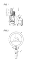
- Fig. 1 is a view showing an example of an object detecting switch in the present embodiment
- Fig. 1 is a view showing an example of an object detecting switch in the present embodiment.
- a limit switch 1 serving as the object detecting switch is a switch that detects position, change, movement, passage, and the like, and outputs an ON signal or an OFF signal according to whether or not detection is made.
- the limit switch 1 is provided with a casing 3, a block part 5, and an actuator 7 for object detection.
- the casing 3 has a switch module 9 arranged in an internal space thereof, and protects the switch module 9 from external forces, water, oil, gas, dust, and the like.
- the casing 3 is made up of a casing main body 3a having an opening through which the switch module 9 is installed in the internal space, and a cover 3b that closes the opening.
- the actuator 7 protrudes from the block part 5, is fixed by a fixing member 11, and is able to rotate about the fixing member 11.
- the position of the actuator 7 when an external force is not applied is the home position.
- the home position of the actuator 7 is a position oriented toward the 12 o'clock direction of a watch.
- Fig. 1 when a force is applied from the left, the actuator 7 rotates in the clockwise direction about the fixing member 11, and thereafter returns to the home position when the force is removed.
- the actuator 7 rotates in the anticlockwise direction about the fixing member 11, and thereafter returns to the home position when the force is removed.
- the actuator 7 When an external force is applied due to contact with a detection body, the actuator 7 transmits the force to the switch module 9 by way of an operation body.
- the operation body has a mechanism such as a spring or a cam, and transmits the motion of the actuator 7 to the switch module 9.
- the switch module 9 outputs a variety of signals, which include a signal indicating that a detection body has been detected, in accordance with the rotation angle of the actuator 7.
- the actuator 7 includes a roller lever 13 that is fixed to the fixing member 11, and a roller 17 that is rotatably attached to the roller lever 13 by means of a rotary shaft 15, and the roller lever 13 rotates about the fixing member 11 due to contact between the roller 17 and the detection body. Because the roller 17 rotates due to contact with the detection body, friction with the detection body is reduced.
- the roller 17 is formed by the sintering of a stainless steel material.
- a stainless steel material used for the roller 17 generally, an Fe-Cr based stainless steel material or an Fe-Cr-Ni based stainless steel material can be used.
- the Fe-Cr based stainless steel material include a martensitic stainless steel material (SUS410) and a ferritic stainless steel material (SUS430).
- the Fe-Cr-Ni based stainless steel material include an austenitic stainless steel material (SUS304), an austenitic-ferritic stainless steel material (SUS329JI), and a precipitation-hardening stainless steel material.
- Examples of the precipitation-hardening stainless steel material include a martensitic stainless steel material (SUS630), an austenitic stainless steel material, a semi-austenitic stainless steel material (SUS631), and an austenitic-ferritic stainless steel material.
- the density of the sintered body of stainless steel is generally 6.4 to 7.0 g/cm 3 , but 6.45 to 6.7 g/cm 3 is preferable.
- the sintered body of stainless steel is impregnated with lubricating oil to improve the lubrication properties of the roller.
- lubricating oil for example, motor oil, spindle oil, mineral oil, paraffin oil, or the like can be used as the lubricating oil.
- the roller 17 may be manufactured by means of sintering, by adding a predetermined amount of copper powder by means of a liquid-phase sintering method and by adding a predetermined amount of ferromolybdenum hard particles. It is therefore possible to improve wear resistance by improving toughness and hardness, and to consequently suppress generation of abraded powder of the roller 17.
- copper is added to an SUS304 sintered body and ferromolybdenum is added to SUS41
- ferromolybdenum may be added to an SUS304 sintered body and copper may be added to SUS410.
- copper and ferromolybdenum may both be added to each of SUS304 and SUS410.
- the amount of copper added is preferably within the range of 1.5 to 3 wt%, because wear resistance is not sufficiently improved if the amount is less than 0.5 wt% and embrittlement is caused if the amount exceeds 4 wt%.
- the amount of ferromolybdenum added is preferably within the range of 3 to 15 wt%. In particular, by adding ferromolybdenum to SUS410, it is possible to enhance the effect of improving wear resistance.
- the rotary shaft 15 is constituted by a stainless steel material and is formed by forging or cutting processing.
- a stainless steel material generally, an Fe-Cr based stainless steel material or an Fe-Cr-Ni based stainless steel material can be used.
- an Fe-Cr based stainless steel material include a martensitic stainless steel material (SUS410) and a ferritic stainless steel material (SUS430).
- Examples of an Fe-Cr-Ni based stainless steel material include an austenitic stainless steel material (SUS304), an austenitic-ferritic stainless steel material (SUS329JI), and a precipitation-hardening stainless steel material.
- Examples of a precipitation-hardening stainless steel material include a martensitic stainless steel material (SUS630), an austenitic stainless steel material, a semi-austenitic stainless steel material (SUS631), and an austenitic-ferritic stainless steel material.
- the stainless steel material used for the rotary shaft 15 it is preferable to use SUS410 which is less likely to become brittle at a temperature lower than SUS430 (close to 0°C). Furthermore, it is preferable that the material used for the rotary shaft 15 is different from the material of the roller 17. This is to prevent adhesion from occurring due to abrasion between members made of the same metal.
- FIG. 2 is a view showing an example of an actuator durability test.
- the limit switch 1 of each of Examples 1 to 4 and Comparative Example is arranged such that the roller 17 of the actuator 7 abuts a rotary wheel 21 which has a recessed portion 23 having a diameter that is less than the outer diameter of the rotary wheel 21, and the rotary wheel 21 is rotated.
- the actuator 7 is positioned at the home position, and at a portion other than the recessed portion 23, the actuator 7 is rotated to an angle determined by the longitudinal length of the actuator 7 and the length between the fixing member 11 and the rotary wheel 21. These states are alternately repeated due to the rotation of the rotary wheel 21.
- the durability test reproduces the motion of the actuator 7 brought about by detection bodies traveling along a production line repeatedly colliding against the limit switch 1.
- the lifespan of the roller 17 was determined by repeating the following operation. Rattling of the roller 17 was examined by stopping the rotary wheel 21 during rotation and then removing the actuator 7 from the limit switch 1, and attaching the actuator 7 to the limit switch 1 and then restarting the rotation of the rotary wheel 21.
- the lifespan of the roller 17 is determined based on the enlargement of the hole of the roller 17 through which the rotary shaft 15 passes, and the rattling of the roller 17 caused by wear of the rotary shaft 15.
- the rattling of the roller 17 was measured using a dimension measurement instrument, in a state in which the actuator is assembled.
- the point in time at which the rattling exceeded a standard value was used to indicate the lifespan of the roller 17, and the travel distance of the roller 17 was calculated from the number of rotations of the rotary wheel 21 and the circumferential length along the outer diameter at this point in time.
- the limit switch 1 was configured by the roller 17 that is formed by using an SUS304 sintered body having a density of 6.7 g/cm 3 , the roller 17 being impregnated with lubricating oil.
- Motor oil type 10W-30 was used as the lubricating oil.
- the oil content of the roller 17 was found to be 7.7 vol%.
- the limit switch 1 was configured by the roller 17 that is formed by using an SUS304 sintered body having a density of 6.5 g/cm 3 , the roller 17 being impregnated with lubricating oil.
- Motor oil type 10W-30 was used as the lubricating oil.
- the oil content of the roller 17 was found to be 11 vol%.
- the limit switch 1 was configured by the roller 17 that is formed with a predetermined amount of copper added thereto by infiltrating copper into an SUS304 sintered body having a density of 6.7 g/cm 3 , the roller 17 being impregnated with lubricating oil.
- Motor oil (type 10W-30) was used as the lubricating oil.
- the oil content of the roller 17 was found to be 9.4 vol%.
- the amount of copper added was 2 wt%.
- the limit switch 1 was configured by the roller 17 that is formed with a predetermined amount of ferromolybdenum added to an SUS410 sintered body having a density of 6.7 g/cm 3 , the roller 17 being impregnated with lubricating oil.
- Motor oil (type 10W-30) was used as the lubricating oil.
- the oil content of the roller 17 was found to be 6.4 vol%.
- the amount of ferromolybdenum added was 8 wt%.
- the strength of the SUS304 sintered body is not sufficient for practical use and dimensional accuracy thereof is not obtained if the density was less than 6.4 g/cm 3 , and therefore the density was not set to be less than 6.45 g/cm 3 .
- the limit switch 1 was configured by the roller 17 that is formed by using an SUS304 sintered body having a density of 6.9 g/cm 3 , the roller 17 being impregnated with lubricating oil.
- Motor oil type 10W-30 was used as the lubricating oil.
- the oil content of the roller 17 was found to be 5 vol%.
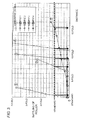
- Fig. 3 is a graph showing results of the durability test.
- the units of the horizontal axis of the graph are based on the travel distance when the roller 17 of Comparative Example reached the life thereof (when the rattling of the roller 17 exceeded the standard value), and the units are shown as multiples thereof.
- the units of the vertical axis of the graph are based on the rattling of the roller 17 of Comparative Example that was determined to have reached its life, and the units are shown as multiples thereof.
- line graphs 1 to 5 correspond to Comparative Example and Examples 1 to 4, respectively.
- the roller 17 of Example 1 has a lifespan that is approximately 6.5 times greater than that of the roller 17 of Comparative Example.
- the roller 17 of Example 2 has a lifespan that is approximately 8 times greater than that of the roller 17 of Comparative Example.
- the roller 17 of Example 3 has a lifespan that is approximately 10 times greater than that of the roller 17 of Comparative Example.
- the roller 17 of Example 4 has a lifespan that is approximately 15 times greater than that of the roller 17 of Comparative Example.
- the actuator 7 in the present embodiment includes: the roller 17 that receives a load of an external force; and a roller lever 13 to which the roller 17 is rotatably attached by means of a rotary shaft 15, the actuator 7 being a displacement member that is displaced in accordance with the load of the force received by the roller 17, wherein the roller 17 is constituted by a sintered body comprising of stainless steel material and impregnated with lubricating oil, and the density of the stainless steel material is in the range of 6.45 to 6.7 g/cm 3 .
- the content of the lubricating oil can be increased by reducing the density of the stainless steel material within a suitable range more than in the conventional technique. Furthermore, physical properties can be improved by adding a suitable additive to the stainless steel material. It is thus possible to reduce wear of the roller 17 and the rotary shaft 15 caused by friction generated between the roller 17 and the rotary shaft 15, and therefore the roller 17 is less likely to rattle. Consequently, durability can be increased.
- a limit switch has been described as an example, but the present invention may also be applied to a microswitch.
Landscapes
- Chemical & Material Sciences (AREA)
- Engineering & Computer Science (AREA)
- Materials Engineering (AREA)
- Mechanical Engineering (AREA)
- Metallurgy (AREA)
- Organic Chemistry (AREA)
- Rotary Switch, Piano Key Switch, And Lever Switch (AREA)
Description
- The present invention relates to an object detecting actuator and an object detecting switch.
- Conventionally, there are known limit switches used on factory production lines to detect that an object such as a product to be processed has been transferred to a predetermined position, and to automatically activate processing machinery. The limit switch is provided with an actuator, and passage of a conveyed object is detected by contact of the object with the actuator.
- For example, Japanese Unexamined Patent Publication No.
2006-164665 (published on June 22, 2006 - Generally, the roller is constituted by a sintered body of stainless steel material as a porous material, and oil is permeated into a plurality of holes. The oil therefore seeps out onto the surface of the roller when the roller is rotating, and lubrication performance of the contact portions of the rotary shaft and the roller is improved.
- In recent years, the loads placed on actuators have been increasing, such as increases in the weight of objects to be detected, and increases in contact frequency or the number of times of contact. Consequently, actuators having an even greater strength are being pursued. For example, high-density sintered bodies (for example, 6.9 g/cm3) are being used to manufacture high-strength actuators.
- However, as the loads have been progressively increasing, it has become no longer possible to ensure a sufficient lifespan with actuators manufactured by means of conventional technique.
- The present invention has been devised to solve the problems described above, and an object thereof is to provide an object detecting actuator and an object detecting switch with increased durability.
- The inventors of the present application have examined the reason for not being able to ensure a sufficient lifespan. As a result, they have discovered that since it is not possible to sufficiently permeate oil into holes of sintered body, there is an increase in friction at contact portions of a roller and a rotary shaft, and the contact portions are therefore easily worn away and the actuator needs to be replaced sooner. In order to reduce the friction, the inventors therefore, by trial and error, reduced the density of the sintered body, increased the number of holes, and increased the amount of the impregnated oil. As a result, it was found that, although the strength decreased commensurately with the decrease in density, the increase in the amount of oil seepage resulted in extending the lifespan, which led to the invention of the present application.
- In order to solve the aforementioned problems, in accordance with one aspect of the present invention, an object detecting actuator comprising of a rotary shaft; a roller lever; and a roller constituted by a sintered body comprising of stainless steel material and impregnated with lubricating oil, wherein a density of stainless steel material is in a range of 6.45 to 6.7 g/cm3, the roller is rotatably attached to the roller lever via the rotary shaft and adapted to receive a load of an external force and adapted to displace the object detecting actuator in accordance with the load of the external force..
- According to this configuration, the content of the lubricating oil can be increased by reducing the density of the stainless steel material more than that in the conventional technique. Consequently, it is possible to reduce wear of the roller and the rotary shaft caused by friction generated in the contact portions of the roller and the rotary shaft, and therefore the roller is less likely to rattle. Thus an object detecting actuator with increased durability is provided.
- In addition, in the object detecting actuator of the present invention, it is possible to use, for example, an austenitic or martensitic stainless steel material as the stainless steel material.
- Furthermore, in the object detecting actuator of the present invention, copper in a range of 1.5 to 3 wt% may be added to the stainless steel material.
- According to this configuration, toughness can be improved by adding a predetermined amount of copper to the stainless steel material, and consequently the generation of abraded powder in the contact portions of the roller and the rotary shaft can be suppressed.
- Furthermore, in the object detecting actuator of the present invention, ferromolybdenum hard particles in a range of 3 to 15 wt% may be added to the stainless steel material.
- According to this configuration, hardness can be increased by adding a predetermined amount of ferromolybdenum hard particles to the stainless steel material, and the generation of abraded powder in the contact portions of the roller and the rotary shaft can also be suppressed.
- Furthermore, in order to solve the aforementioned problem, in accordance with another aspect of the present invention, an object detecting switch of the present invention includes the above object detecting actuator and a signal output unit that outputs a signal corresponding to the position of the object detecting actuator.
- According to this configuration, an object detecting switch with increased durability can be provided. Thus, the present invention has the effect with which durability can be increased.
-
Fig. 1 is a view showing an example of an object detecting switch in the present embodiment; -
Fig. 2 is a view showing an example of an actuator durability test; and -
Fig. 3 is a graph showing results of the durability test. - An embodiment of the present invention will be described with reference to the drawings. In the following description, like symbols are denoted to like components. The names and functions thereof are also the same. Accordingly, detailed descriptions thereof are not repeated.
-
Fig. 1 is a view showing an example of an object detecting switch in the present embodiment. As shown inFig. 1 , alimit switch 1 serving as the object detecting switch is a switch that detects position, change, movement, passage, and the like, and outputs an ON signal or an OFF signal according to whether or not detection is made. - The
limit switch 1 is provided with acasing 3, ablock part 5, and anactuator 7 for object detection. Thecasing 3 has aswitch module 9 arranged in an internal space thereof, and protects theswitch module 9 from external forces, water, oil, gas, dust, and the like. Thecasing 3 is made up of a casingmain body 3a having an opening through which theswitch module 9 is installed in the internal space, and acover 3b that closes the opening. - The
actuator 7 protrudes from theblock part 5, is fixed by afixing member 11, and is able to rotate about thefixing member 11. The position of theactuator 7 when an external force is not applied is the home position. Here, the home position of theactuator 7 is a position oriented toward the 12 o'clock direction of a watch. InFig. 1 , when a force is applied from the left, theactuator 7 rotates in the clockwise direction about thefixing member 11, and thereafter returns to the home position when the force is removed. On the other hand, when a force is applied from the right, theactuator 7 rotates in the anticlockwise direction about thefixing member 11, and thereafter returns to the home position when the force is removed. - When an external force is applied due to contact with a detection body, the
actuator 7 transmits the force to theswitch module 9 by way of an operation body. Basically, the operation body has a mechanism such as a spring or a cam, and transmits the motion of theactuator 7 to theswitch module 9. Theswitch module 9 outputs a variety of signals, which include a signal indicating that a detection body has been detected, in accordance with the rotation angle of theactuator 7. - The
actuator 7 includes aroller lever 13 that is fixed to thefixing member 11, and aroller 17 that is rotatably attached to theroller lever 13 by means of arotary shaft 15, and theroller lever 13 rotates about thefixing member 11 due to contact between theroller 17 and the detection body. Because theroller 17 rotates due to contact with the detection body, friction with the detection body is reduced. - Furthermore, the
roller 17 is formed by the sintering of a stainless steel material. For the stainless steel material used for theroller 17, generally, an Fe-Cr based stainless steel material or an Fe-Cr-Ni based stainless steel material can be used. Examples of the Fe-Cr based stainless steel material include a martensitic stainless steel material (SUS410) and a ferritic stainless steel material (SUS430). Examples of the Fe-Cr-Ni based stainless steel material include an austenitic stainless steel material (SUS304), an austenitic-ferritic stainless steel material (SUS329JI), and a precipitation-hardening stainless steel material. Examples of the precipitation-hardening stainless steel material include a martensitic stainless steel material (SUS630), an austenitic stainless steel material, a semi-austenitic stainless steel material (SUS631), and an austenitic-ferritic stainless steel material. - The density of the sintered body of stainless steel is generally 6.4 to 7.0 g/cm3, but 6.45 to 6.7 g/cm3 is preferable. In addition, the sintered body of stainless steel is impregnated with lubricating oil to improve the lubrication properties of the roller. For example, motor oil, spindle oil, mineral oil, paraffin oil, or the like can be used as the lubricating oil.
- Furthermore, the
roller 17 may be manufactured by means of sintering, by adding a predetermined amount of copper powder by means of a liquid-phase sintering method and by adding a predetermined amount of ferromolybdenum hard particles. It is therefore possible to improve wear resistance by improving toughness and hardness, and to consequently suppress generation of abraded powder of theroller 17. In particular, although it is preferable that copper is added to an SUS304 sintered body and ferromolybdenum is added toSUS41 0, ferromolybdenum may be added to an SUS304 sintered body and copper may be added to SUS410. Furthermore, copper and ferromolybdenum may both be added to each of SUS304 and SUS410. - It should be noted that, the amount of copper added is preferably within the range of 1.5 to 3 wt%, because wear resistance is not sufficiently improved if the amount is less than 0.5 wt% and embrittlement is caused if the amount exceeds 4 wt%. The amount of ferromolybdenum added is preferably within the range of 3 to 15 wt%. In particular, by adding ferromolybdenum to SUS410, it is possible to enhance the effect of improving wear resistance.
- The
rotary shaft 15 is constituted by a stainless steel material and is formed by forging or cutting processing. For the stainless steel material, generally, an Fe-Cr based stainless steel material or an Fe-Cr-Ni based stainless steel material can be used. Examples of an Fe-Cr based stainless steel material include a martensitic stainless steel material (SUS410) and a ferritic stainless steel material (SUS430). Examples of an Fe-Cr-Ni based stainless steel material include an austenitic stainless steel material (SUS304), an austenitic-ferritic stainless steel material (SUS329JI), and a precipitation-hardening stainless steel material. Examples of a precipitation-hardening stainless steel material include a martensitic stainless steel material (SUS630), an austenitic stainless steel material, a semi-austenitic stainless steel material (SUS631), and an austenitic-ferritic stainless steel material. - It should be noted that, for the stainless steel material used for the
rotary shaft 15, it is preferable to use SUS410 which is less likely to become brittle at a temperature lower than SUS430 (close to 0°C). Furthermore, it is preferable that the material used for therotary shaft 15 is different from the material of theroller 17. This is to prevent adhesion from occurring due to abrasion between members made of the same metal. - Next, the present invention will be described in more detail by means of the following Examples 1 to 4 and Comparative Example.
Fig. 2 is a view showing an example of an actuator durability test. As shown inFig. 2 , thelimit switch 1 of each of Examples 1 to 4 and Comparative Example is arranged such that theroller 17 of theactuator 7 abuts arotary wheel 21 which has a recessedportion 23 having a diameter that is less than the outer diameter of therotary wheel 21, and therotary wheel 21 is rotated. - At the recessed
portion 23, theactuator 7 is positioned at the home position, and at a portion other than the recessedportion 23, theactuator 7 is rotated to an angle determined by the longitudinal length of theactuator 7 and the length between the fixingmember 11 and therotary wheel 21. These states are alternately repeated due to the rotation of therotary wheel 21. - Furthermore, when the
roller 17 of theactuator 7 comes into contact with the portion other than the recessedportion 23, a load of a certain level or more is applied to theroller 17, and theroller 17 rotates in accordance with the rotating motion of therotary wheel 21. In this way, the durability test reproduces the motion of theactuator 7 brought about by detection bodies traveling along a production line repeatedly colliding against thelimit switch 1. - In the durability test, the lifespan of the
roller 17 was determined by repeating the following operation. Rattling of theroller 17 was examined by stopping therotary wheel 21 during rotation and then removing theactuator 7 from thelimit switch 1, and attaching theactuator 7 to thelimit switch 1 and then restarting the rotation of therotary wheel 21. - The lifespan of the
roller 17 is determined based on the enlargement of the hole of theroller 17 through which therotary shaft 15 passes, and the rattling of theroller 17 caused by wear of therotary shaft 15. The rattling of theroller 17 was measured using a dimension measurement instrument, in a state in which the actuator is assembled. Here, the point in time at which the rattling exceeded a standard value was used to indicate the lifespan of theroller 17, and the travel distance of theroller 17 was calculated from the number of rotations of therotary wheel 21 and the circumferential length along the outer diameter at this point in time. - It should be noted that an SUS410 stainless steel material was used for the
rotary shaft 15 of Examples 1 to 4 and Comparative Example. - In Example 1, the
limit switch 1 was configured by theroller 17 that is formed by using an SUS304 sintered body having a density of 6.7 g/cm3, theroller 17 being impregnated with lubricating oil. Motor oil (type 10W-30) was used as the lubricating oil. The oil content of theroller 17 was found to be 7.7 vol%. - In Example 2, the
limit switch 1 was configured by theroller 17 that is formed by using an SUS304 sintered body having a density of 6.5 g/cm3, theroller 17 being impregnated with lubricating oil. Motor oil (type 10W-30) was used as the lubricating oil. The oil content of theroller 17 was found to be 11 vol%. - In Example 3, the
limit switch 1 was configured by theroller 17 that is formed with a predetermined amount of copper added thereto by infiltrating copper into an SUS304 sintered body having a density of 6.7 g/cm3, theroller 17 being impregnated with lubricating oil. Motor oil (type 10W-30) was used as the lubricating oil. The oil content of theroller 17 was found to be 9.4 vol%. The amount of copper added was 2 wt%. - In Example 4, the
limit switch 1 was configured by theroller 17 that is formed with a predetermined amount of ferromolybdenum added to an SUS410 sintered body having a density of 6.7 g/cm3, theroller 17 being impregnated with lubricating oil. Motor oil (type 10W-30) was used as the lubricating oil. The oil content of theroller 17 was found to be 6.4 vol%. The amount of ferromolybdenum added was 8 wt%. - It was understood that the strength of the SUS304 sintered body is not sufficient for practical use and dimensional accuracy thereof is not obtained if the density was less than 6.4 g/cm3, and therefore the density was not set to be less than 6.45 g/cm3.
- In Comparative Example, the
limit switch 1 was configured by theroller 17 that is formed by using an SUS304 sintered body having a density of 6.9 g/cm3, theroller 17 being impregnated with lubricating oil. Motor oil (type 10W-30) was used as the lubricating oil. The oil content of theroller 17 was found to be 5 vol%. -
Fig. 3 is a graph showing results of the durability test. The units of the horizontal axis of the graph are based on the travel distance when theroller 17 of Comparative Example reached the life thereof (when the rattling of theroller 17 exceeded the standard value), and the units are shown as multiples thereof. The units of the vertical axis of the graph are based on the rattling of theroller 17 of Comparative Example that was determined to have reached its life, and the units are shown as multiples thereof. As shown inFig. 3 ,line graphs 1 to 5 correspond to Comparative Example and Examples 1 to 4, respectively. - As shown by the
line graphs roller 17 of Example 1 has a lifespan that is approximately 6.5 times greater than that of theroller 17 of Comparative Example. As shown by theline graphs roller 17 of Example 2 has a lifespan that is approximately 8 times greater than that of theroller 17 of Comparative Example. As shown by theline graphs roller 17 of Example 3 has a lifespan that is approximately 10 times greater than that of theroller 17 of Comparative Example. As shown by theline graphs roller 17 of Example 4 has a lifespan that is approximately 15 times greater than that of theroller 17 of Comparative Example. - As shown by the results obtained from the durability test, it was possible to extend the lifespan of the
roller 17 commensurately with decrease in density of the SUS304 sintered body within the range of 6.45 to 6.7 g/cm3. It is considered that it was possible to suppress wear between theroller 17 and therotary shaft 15 since the content of the lubricating oil can be increased commensurately with decrease in density within the range of 6.45 to 6.7 g/cm3. - Furthermore, it was possible to further extend the lifespan of the
roller 17 by adding a predetermined amount of copper to the SUS304 sintered body. It is considered that, in addition to the lubrication effect of the lubricating oil, the effect of suppressing the generation of abrasion powder (wear resistance) can be improved as a result of increasing the toughness of the sintered body by adding copper to the sintered body. - Furthermore, it was possible to further extend the lifespan of the
roller 17 by changing to an SUS410 sintered body and adding a predetermined amount of ferromolybdenum to the sintered body. It is considered that it was possible to increase the wear resistance of the sintered body as SUS410 has excellent hardening properties and as a result of adding ferromolybdenum to the sintered body. - As described above, the
actuator 7 in the present embodiment includes: theroller 17 that receives a load of an external force; and aroller lever 13 to which theroller 17 is rotatably attached by means of arotary shaft 15, theactuator 7 being a displacement member that is displaced in accordance with the load of the force received by theroller 17, wherein theroller 17 is constituted by a sintered body comprising of stainless steel material and impregnated with lubricating oil, and the density of the stainless steel material is in the range of 6.45 to 6.7 g/cm3. - Therefore, the content of the lubricating oil can be increased by reducing the density of the stainless steel material within a suitable range more than in the conventional technique. Furthermore, physical properties can be improved by adding a suitable additive to the stainless steel material. It is thus possible to reduce wear of the
roller 17 and therotary shaft 15 caused by friction generated between theroller 17 and therotary shaft 15, and therefore theroller 17 is less likely to rattle. Consequently, durability can be increased. - It should be noted that, in the present embodiment, a limit switch has been described as an example, but the present invention may also be applied to a microswitch.
- The present invention is not limited to these embodiments, and a variety of alterations are possible within the scope indicated in the claims. In other words, embodiments obtained by combining technical means appropriately altered within the scope indicated in the claims are also included in the technical scope of the present invention.
Claims (6)
- An object detecting actuator (7) comprising:a rotary shaft (15);a roller lever (13); and
a roller (17) constituted by a sintered body comprising of stainless steel material and impregnated with lubricating oil, wherein a density of stainless steel material is in a range of 6.45 to 6.7 g/cm3, the roller (17) is rotatably attached to the roller lever (13) via the rotary shaft (15) and adapted to receive a load of an external force and adapted to displace the object detecting actuator (7) in accordance with the load of the external force. - The object detecting actuator (7) according to claim 1, wherein the stainless steel material is an austenitic stainless steel material.
- The object detecting actuator (7) according to claim 1, wherein the stainless steel material is a martensitic stainless steel material.
- The object detecting actuator (7) according to any of claims 1 to 3, wherein the sintered body further comprises copper in a range of 1.5 to 3 wt% of the stainless steel.
- The object detecting actuator (7) according to any of claims 1 to 4, wherein the sintered body further comprises ferromolybdenum hard particles in a range of 3 to 15 wt% of stainless steel material.
- An object detecting switch (1) comprising the object detecting actuator (7) according to any of claims 1 to 5.
Applications Claiming Priority (1)
| Application Number | Priority Date | Filing Date | Title |
|---|---|---|---|
| JP2012147860A JP6035906B2 (en) | 2012-06-29 | 2012-06-29 | Object detection actuator and object detection switch |
Publications (3)
| Publication Number | Publication Date |
|---|---|
| EP2680292A2 true EP2680292A2 (en) | 2014-01-01 |
| EP2680292A3 EP2680292A3 (en) | 2015-01-14 |
| EP2680292B1 EP2680292B1 (en) | 2016-01-20 |
Family
ID=48669800
Family Applications (1)
| Application Number | Title | Priority Date | Filing Date |
|---|---|---|---|
| EP13173096.2A Active EP2680292B1 (en) | 2012-06-29 | 2013-06-20 | Object detecting actuator and object detecting switch |
Country Status (5)
| Country | Link |
|---|---|
| US (1) | US9156625B2 (en) |
| EP (1) | EP2680292B1 (en) |
| JP (1) | JP6035906B2 (en) |
| CN (1) | CN103515136B (en) |
| ES (1) | ES2564733T3 (en) |
Families Citing this family (6)
| Publication number | Priority date | Publication date | Assignee | Title |
|---|---|---|---|---|
| US11349879B1 (en) | 2013-07-28 | 2022-05-31 | Secureauth Corporation | System and method for multi-transaction policy orchestration with first and second level derived policies for authentication and authorization |
| USD751997S1 (en) * | 2013-08-08 | 2016-03-22 | Omron Corporation | Box cover for limit switch |
| USD778842S1 (en) * | 2013-08-08 | 2017-02-14 | Omron Corporation | Box cover for limit switch |
| US10325259B1 (en) | 2014-03-29 | 2019-06-18 | Acceptto Corporation | Dynamic authorization with adaptive levels of assurance |
| JP2016122547A (en) | 2014-12-24 | 2016-07-07 | オムロン株式会社 | Limit switch |
| CN110853965A (en) * | 2019-11-22 | 2020-02-28 | 中国航发沈阳黎明航空发动机有限责任公司 | A double roller automatic reset stroke trigger device |
Citations (1)
| Publication number | Priority date | Publication date | Assignee | Title |
|---|---|---|---|---|
| JP2006164665A (en) | 2004-12-06 | 2006-06-22 | Sumitomo Chemical Co Ltd | Limit switch and automatic transfer device |
Family Cites Families (12)
| Publication number | Priority date | Publication date | Assignee | Title |
|---|---|---|---|---|
| US4762972A (en) * | 1986-11-14 | 1988-08-09 | Otto Engineering, Inc. | Enclosed externally actuated switch assembly |
| JP2617334B2 (en) * | 1988-05-09 | 1997-06-04 | 菊池 勇 | Sintered alloy material and method for producing the same |
| US5276299A (en) * | 1991-11-05 | 1994-01-04 | Otis Elevator Company | Elevator limit switch |
| JP2750821B2 (en) * | 1994-10-17 | 1998-05-13 | プルトンチエン株式会社 | Roller type linear guide device |
| JPH10250818A (en) * | 1997-03-11 | 1998-09-22 | Tsubakimoto Chain Co | Oil-impregnated sintered bush conveyor chain |
| JPH11348614A (en) * | 1998-06-08 | 1999-12-21 | Oiles Ind Co Ltd | Roller for automobile seat rail |
| US6664487B2 (en) * | 2001-07-10 | 2003-12-16 | Omron Corporation | Limit switches |
| JP2004247255A (en) * | 2003-02-17 | 2004-09-02 | Yamatake Corp | Limit switch |
| GB2440857B (en) * | 2003-07-31 | 2008-09-10 | Komatsu Mfg Co Ltd | Sintered sliding member and connecting device |
| US8911662B2 (en) * | 2006-12-29 | 2014-12-16 | Hoganas Ab | Powder, method of manufacturing a component and component |
| WO2010106909A1 (en) | 2009-03-19 | 2010-09-23 | Ntn株式会社 | Sintered metallic bearing and fluid dynamic bearing device equipped with the bearing |
| JP4978730B2 (en) * | 2010-12-03 | 2012-07-18 | オムロン株式会社 | switch |
-
2012
- 2012-06-29 JP JP2012147860A patent/JP6035906B2/en not_active Expired - Fee Related
-
2013
- 2013-06-20 ES ES13173096.2T patent/ES2564733T3/en active Active
- 2013-06-20 EP EP13173096.2A patent/EP2680292B1/en active Active
- 2013-06-20 US US13/923,111 patent/US9156625B2/en active Active
- 2013-06-21 CN CN201310250578.8A patent/CN103515136B/en active Active
Patent Citations (1)
| Publication number | Priority date | Publication date | Assignee | Title |
|---|---|---|---|---|
| JP2006164665A (en) | 2004-12-06 | 2006-06-22 | Sumitomo Chemical Co Ltd | Limit switch and automatic transfer device |
Also Published As
| Publication number | Publication date |
|---|---|
| EP2680292B1 (en) | 2016-01-20 |
| JP6035906B2 (en) | 2016-11-30 |
| CN103515136A (en) | 2014-01-15 |
| US20140000409A1 (en) | 2014-01-02 |
| JP2014011069A (en) | 2014-01-20 |
| ES2564733T3 (en) | 2016-03-28 |
| EP2680292A3 (en) | 2015-01-14 |
| CN103515136B (en) | 2016-05-18 |
| US9156625B2 (en) | 2015-10-13 |
Similar Documents
| Publication | Publication Date | Title |
|---|---|---|
| EP2680292B1 (en) | Object detecting actuator and object detecting switch | |
| CN102197234B (en) | Device comprising actuating element of variable-speed gearbox | |
| US8876396B2 (en) | Roller bearing with knurled wear resistant exterior surface and method of manufacturing the same | |
| CN100462722C (en) | Rotation speed detection device and load measurement device for rolling bearing unit | |
| WO2017051836A1 (en) | Bearing device for vehicle wheel | |
| CN110646202B (en) | Method and device for detecting wear of a bearing | |
| CN101981355B (en) | For supporting the band of shift rail for determining the system of the sensor of position | |
| US20080277608A1 (en) | Method for operation of an actuating drive | |
| JP5938465B2 (en) | Floating seal | |
| WO2014124033A1 (en) | Torque sensor bearing arrangement and method | |
| CN105890513B (en) | For obtaining the sensor module of the rotation angle of the rotating member in vehicle | |
| US20110110618A1 (en) | Bearing ring | |
| US8395475B2 (en) | Bearing device having position indicator | |
| JP5157849B2 (en) | Manufacturing method of seal | |
| JP5965988B2 (en) | Floating seal | |
| JP4949274B2 (en) | Floating seal | |
| EP0915319A1 (en) | Moving body and means for detecting position thereof | |
| JP5021762B2 (en) | Sensor device for measuring the rotational movement of a wheel bearing | |
| KR102061189B1 (en) | Ball bearing with aligning ring | |
| CN204784354U (en) | Machinery stop gear | |
| CN203604434U (en) | Closed high-speed low-noise angular contact ball spindle bearing | |
| JP2017058009A (en) | Wheel bearing device | |
| JP2006105262A (en) | Rolling device | |
| JP2009243883A (en) | Contact detector and its detection needle | |
| JP5213321B2 (en) | Magnetic encoder and rolling bearing |
Legal Events
| Date | Code | Title | Description |
|---|---|---|---|
| PUAI | Public reference made under article 153(3) epc to a published international application that has entered the european phase |
Free format text: ORIGINAL CODE: 0009012 |
|
| AK | Designated contracting states |
Kind code of ref document: A2 Designated state(s): AL AT BE BG CH CY CZ DE DK EE ES FI FR GB GR HR HU IE IS IT LI LT LU LV MC MK MT NL NO PL PT RO RS SE SI SK SM TR |
|
| AX | Request for extension of the european patent |
Extension state: BA ME |
|
| PUAL | Search report despatched |
Free format text: ORIGINAL CODE: 0009013 |
|
| AK | Designated contracting states |
Kind code of ref document: A3 Designated state(s): AL AT BE BG CH CY CZ DE DK EE ES FI FR GB GR HR HU IE IS IT LI LT LU LV MC MK MT NL NO PL PT RO RS SE SI SK SM TR |
|
| AX | Request for extension of the european patent |
Extension state: BA ME |
|
| RIC1 | Information provided on ipc code assigned before grant |
Ipc: H01H 21/28 20060101AFI20141210BHEP Ipc: B65G 43/08 20060101ALI20141210BHEP Ipc: C22C 33/02 20060101ALI20141210BHEP |
|
| 17P | Request for examination filed |
Effective date: 20150331 |
|
| RBV | Designated contracting states (corrected) |
Designated state(s): AL AT BE BG CH CY CZ DE DK EE ES FI FR GB GR HR HU IE IS IT LI LT LU LV MC MK MT NL NO PL PT RO RS SE SI SK SM TR |
|
| GRAP | Despatch of communication of intention to grant a patent |
Free format text: ORIGINAL CODE: EPIDOSNIGR1 |
|
| RIN1 | Information on inventor provided before grant (corrected) |
Inventor name: TOBITA, KOKICHI Inventor name: MISHIMA, JUNYA Inventor name: TAKAHASHI, MANABU Inventor name: HAYASE, TETSUO |
|
| INTG | Intention to grant announced |
Effective date: 20150715 |
|
| GRAS | Grant fee paid |
Free format text: ORIGINAL CODE: EPIDOSNIGR3 |
|
| GRAA | (expected) grant |
Free format text: ORIGINAL CODE: 0009210 |
|
| AK | Designated contracting states |
Kind code of ref document: B1 Designated state(s): AL AT BE BG CH CY CZ DE DK EE ES FI FR GB GR HR HU IE IS IT LI LT LU LV MC MK MT NL NO PL PT RO RS SE SI SK SM TR |
|
| REG | Reference to a national code |
Ref country code: GB Ref legal event code: FG4D |
|
| REG | Reference to a national code |
Ref country code: CH Ref legal event code: EP |
|
| REG | Reference to a national code |
Ref country code: IE Ref legal event code: FG4D |
|
| REG | Reference to a national code |
Ref country code: AT Ref legal event code: REF Ref document number: 772064 Country of ref document: AT Kind code of ref document: T Effective date: 20160215 |
|
| REG | Reference to a national code |
Ref country code: DE Ref legal event code: R096 Ref document number: 602013004699 Country of ref document: DE |
|
| REG | Reference to a national code |
Ref country code: ES Ref legal event code: FG2A Ref document number: 2564733 Country of ref document: ES Kind code of ref document: T3 Effective date: 20160328 |
|
| REG | Reference to a national code |
Ref country code: LT Ref legal event code: MG4D Ref country code: NL Ref legal event code: MP Effective date: 20160120 |
|
| REG | Reference to a national code |
Ref country code: AT Ref legal event code: MK05 Ref document number: 772064 Country of ref document: AT Kind code of ref document: T Effective date: 20160120 |
|
| PG25 | Lapsed in a contracting state [announced via postgrant information from national office to epo] |
Ref country code: NL Free format text: LAPSE BECAUSE OF FAILURE TO SUBMIT A TRANSLATION OF THE DESCRIPTION OR TO PAY THE FEE WITHIN THE PRESCRIBED TIME-LIMIT Effective date: 20160120 |
|
| PG25 | Lapsed in a contracting state [announced via postgrant information from national office to epo] |
Ref country code: FI Free format text: LAPSE BECAUSE OF FAILURE TO SUBMIT A TRANSLATION OF THE DESCRIPTION OR TO PAY THE FEE WITHIN THE PRESCRIBED TIME-LIMIT Effective date: 20160120 Ref country code: GR Free format text: LAPSE BECAUSE OF FAILURE TO SUBMIT A TRANSLATION OF THE DESCRIPTION OR TO PAY THE FEE WITHIN THE PRESCRIBED TIME-LIMIT Effective date: 20160421 Ref country code: HR Free format text: LAPSE BECAUSE OF FAILURE TO SUBMIT A TRANSLATION OF THE DESCRIPTION OR TO PAY THE FEE WITHIN THE PRESCRIBED TIME-LIMIT Effective date: 20160120 Ref country code: NO Free format text: LAPSE BECAUSE OF FAILURE TO SUBMIT A TRANSLATION OF THE DESCRIPTION OR TO PAY THE FEE WITHIN THE PRESCRIBED TIME-LIMIT Effective date: 20160420 |
|
| PG25 | Lapsed in a contracting state [announced via postgrant information from national office to epo] |
Ref country code: IS Free format text: LAPSE BECAUSE OF FAILURE TO SUBMIT A TRANSLATION OF THE DESCRIPTION OR TO PAY THE FEE WITHIN THE PRESCRIBED TIME-LIMIT Effective date: 20160520 Ref country code: PT Free format text: LAPSE BECAUSE OF FAILURE TO SUBMIT A TRANSLATION OF THE DESCRIPTION OR TO PAY THE FEE WITHIN THE PRESCRIBED TIME-LIMIT Effective date: 20160520 Ref country code: RS Free format text: LAPSE BECAUSE OF FAILURE TO SUBMIT A TRANSLATION OF THE DESCRIPTION OR TO PAY THE FEE WITHIN THE PRESCRIBED TIME-LIMIT Effective date: 20160120 Ref country code: AT Free format text: LAPSE BECAUSE OF FAILURE TO SUBMIT A TRANSLATION OF THE DESCRIPTION OR TO PAY THE FEE WITHIN THE PRESCRIBED TIME-LIMIT Effective date: 20160120 Ref country code: SE Free format text: LAPSE BECAUSE OF FAILURE TO SUBMIT A TRANSLATION OF THE DESCRIPTION OR TO PAY THE FEE WITHIN THE PRESCRIBED TIME-LIMIT Effective date: 20160120 Ref country code: PL Free format text: LAPSE BECAUSE OF FAILURE TO SUBMIT A TRANSLATION OF THE DESCRIPTION OR TO PAY THE FEE WITHIN THE PRESCRIBED TIME-LIMIT Effective date: 20160120 Ref country code: LT Free format text: LAPSE BECAUSE OF FAILURE TO SUBMIT A TRANSLATION OF THE DESCRIPTION OR TO PAY THE FEE WITHIN THE PRESCRIBED TIME-LIMIT Effective date: 20160120 Ref country code: LV Free format text: LAPSE BECAUSE OF FAILURE TO SUBMIT A TRANSLATION OF THE DESCRIPTION OR TO PAY THE FEE WITHIN THE PRESCRIBED TIME-LIMIT Effective date: 20160120 |
|
| REG | Reference to a national code |
Ref country code: DE Ref legal event code: R097 Ref document number: 602013004699 Country of ref document: DE |
|
| PG25 | Lapsed in a contracting state [announced via postgrant information from national office to epo] |
Ref country code: EE Free format text: LAPSE BECAUSE OF FAILURE TO SUBMIT A TRANSLATION OF THE DESCRIPTION OR TO PAY THE FEE WITHIN THE PRESCRIBED TIME-LIMIT Effective date: 20160120 Ref country code: DK Free format text: LAPSE BECAUSE OF FAILURE TO SUBMIT A TRANSLATION OF THE DESCRIPTION OR TO PAY THE FEE WITHIN THE PRESCRIBED TIME-LIMIT Effective date: 20160120 |
|
| PLBE | No opposition filed within time limit |
Free format text: ORIGINAL CODE: 0009261 |
|
| STAA | Information on the status of an ep patent application or granted ep patent |
Free format text: STATUS: NO OPPOSITION FILED WITHIN TIME LIMIT |
|
| PG25 | Lapsed in a contracting state [announced via postgrant information from national office to epo] |
Ref country code: SK Free format text: LAPSE BECAUSE OF FAILURE TO SUBMIT A TRANSLATION OF THE DESCRIPTION OR TO PAY THE FEE WITHIN THE PRESCRIBED TIME-LIMIT Effective date: 20160120 Ref country code: RO Free format text: LAPSE BECAUSE OF FAILURE TO SUBMIT A TRANSLATION OF THE DESCRIPTION OR TO PAY THE FEE WITHIN THE PRESCRIBED TIME-LIMIT Effective date: 20160120 Ref country code: CZ Free format text: LAPSE BECAUSE OF FAILURE TO SUBMIT A TRANSLATION OF THE DESCRIPTION OR TO PAY THE FEE WITHIN THE PRESCRIBED TIME-LIMIT Effective date: 20160120 Ref country code: SM Free format text: LAPSE BECAUSE OF FAILURE TO SUBMIT A TRANSLATION OF THE DESCRIPTION OR TO PAY THE FEE WITHIN THE PRESCRIBED TIME-LIMIT Effective date: 20160120 |
|
| 26N | No opposition filed |
Effective date: 20161021 |
|
| PG25 | Lapsed in a contracting state [announced via postgrant information from national office to epo] |
Ref country code: BE Free format text: LAPSE BECAUSE OF FAILURE TO SUBMIT A TRANSLATION OF THE DESCRIPTION OR TO PAY THE FEE WITHIN THE PRESCRIBED TIME-LIMIT Effective date: 20160120 |
|
| PG25 | Lapsed in a contracting state [announced via postgrant information from national office to epo] |
Ref country code: MC Free format text: LAPSE BECAUSE OF FAILURE TO SUBMIT A TRANSLATION OF THE DESCRIPTION OR TO PAY THE FEE WITHIN THE PRESCRIBED TIME-LIMIT Effective date: 20160120 |
|
| REG | Reference to a national code |
Ref country code: CH Ref legal event code: PL |
|
| PG25 | Lapsed in a contracting state [announced via postgrant information from national office to epo] |
Ref country code: BG Free format text: LAPSE BECAUSE OF FAILURE TO SUBMIT A TRANSLATION OF THE DESCRIPTION OR TO PAY THE FEE WITHIN THE PRESCRIBED TIME-LIMIT Effective date: 20160420 Ref country code: SI Free format text: LAPSE BECAUSE OF FAILURE TO SUBMIT A TRANSLATION OF THE DESCRIPTION OR TO PAY THE FEE WITHIN THE PRESCRIBED TIME-LIMIT Effective date: 20160120 |
|
| REG | Reference to a national code |
Ref country code: IE Ref legal event code: MM4A |
|
| REG | Reference to a national code |
Ref country code: FR Ref legal event code: ST Effective date: 20170228 |
|
| PG25 | Lapsed in a contracting state [announced via postgrant information from national office to epo] |
Ref country code: LI Free format text: LAPSE BECAUSE OF NON-PAYMENT OF DUE FEES Effective date: 20160630 Ref country code: CH Free format text: LAPSE BECAUSE OF NON-PAYMENT OF DUE FEES Effective date: 20160630 Ref country code: FR Free format text: LAPSE BECAUSE OF NON-PAYMENT OF DUE FEES Effective date: 20160630 |
|
| PG25 | Lapsed in a contracting state [announced via postgrant information from national office to epo] |
Ref country code: IE Free format text: LAPSE BECAUSE OF NON-PAYMENT OF DUE FEES Effective date: 20160620 |
|
| GBPC | Gb: european patent ceased through non-payment of renewal fee |
Effective date: 20170620 |
|
| PG25 | Lapsed in a contracting state [announced via postgrant information from national office to epo] |
Ref country code: GB Free format text: LAPSE BECAUSE OF NON-PAYMENT OF DUE FEES Effective date: 20170620 |
|
| PG25 | Lapsed in a contracting state [announced via postgrant information from national office to epo] |
Ref country code: CY Free format text: LAPSE BECAUSE OF FAILURE TO SUBMIT A TRANSLATION OF THE DESCRIPTION OR TO PAY THE FEE WITHIN THE PRESCRIBED TIME-LIMIT Effective date: 20160120 Ref country code: HU Free format text: LAPSE BECAUSE OF FAILURE TO SUBMIT A TRANSLATION OF THE DESCRIPTION OR TO PAY THE FEE WITHIN THE PRESCRIBED TIME-LIMIT; INVALID AB INITIO Effective date: 20130620 |
|
| PG25 | Lapsed in a contracting state [announced via postgrant information from national office to epo] |
Ref country code: MK Free format text: LAPSE BECAUSE OF FAILURE TO SUBMIT A TRANSLATION OF THE DESCRIPTION OR TO PAY THE FEE WITHIN THE PRESCRIBED TIME-LIMIT Effective date: 20160120 Ref country code: LU Free format text: LAPSE BECAUSE OF NON-PAYMENT OF DUE FEES Effective date: 20160620 Ref country code: TR Free format text: LAPSE BECAUSE OF FAILURE TO SUBMIT A TRANSLATION OF THE DESCRIPTION OR TO PAY THE FEE WITHIN THE PRESCRIBED TIME-LIMIT Effective date: 20160120 Ref country code: MT Free format text: LAPSE BECAUSE OF NON-PAYMENT OF DUE FEES Effective date: 20160630 |
|
| PG25 | Lapsed in a contracting state [announced via postgrant information from national office to epo] |
Ref country code: AL Free format text: LAPSE BECAUSE OF FAILURE TO SUBMIT A TRANSLATION OF THE DESCRIPTION OR TO PAY THE FEE WITHIN THE PRESCRIBED TIME-LIMIT Effective date: 20160120 |
|
| PGFP | Annual fee paid to national office [announced via postgrant information from national office to epo] |
Ref country code: DE Payment date: 20250618 Year of fee payment: 13 |
|
| PGFP | Annual fee paid to national office [announced via postgrant information from national office to epo] |
Ref country code: ES Payment date: 20250718 Year of fee payment: 13 |
|
| PGFP | Annual fee paid to national office [announced via postgrant information from national office to epo] |
Ref country code: IT Payment date: 20250630 Year of fee payment: 13 |