EP2680100B1 - Housings that move using a link that slidingly engages cams - Google Patents
Housings that move using a link that slidingly engages cams Download PDFInfo
- Publication number
- EP2680100B1 EP2680100B1 EP13173814.8A EP13173814A EP2680100B1 EP 2680100 B1 EP2680100 B1 EP 2680100B1 EP 13173814 A EP13173814 A EP 13173814A EP 2680100 B1 EP2680100 B1 EP 2680100B1
- Authority
- EP
- European Patent Office
- Prior art keywords
- housing
- cam
- disposed
- link
- housings
- Prior art date
- Legal status (The legal status is an assumption and is not a legal conclusion. Google has not performed a legal analysis and makes no representation as to the accuracy of the status listed.)
- Active
Links
Images


Classifications
-
- G—PHYSICS
- G06—COMPUTING; CALCULATING OR COUNTING
- G06F—ELECTRIC DIGITAL DATA PROCESSING
- G06F1/00—Details not covered by groups G06F3/00 - G06F13/00 and G06F21/00
- G06F1/16—Constructional details or arrangements
- G06F1/1613—Constructional details or arrangements for portable computers
- G06F1/1615—Constructional details or arrangements for portable computers with several enclosures having relative motions, each enclosure supporting at least one I/O or computing function
- G06F1/1624—Constructional details or arrangements for portable computers with several enclosures having relative motions, each enclosure supporting at least one I/O or computing function with sliding enclosures, e.g. sliding keyboard or display
Definitions
- the present disclosure relates generally to multi-housing apparatuses and more particularly to apparatuses having housings that move relative to one another.
- Portable electronic devices include, for example, several types of mobile stations such as simple cellular telephones, smart telephones, wireless personal digital assistants (PDAs), and laptop computers with wireless 802.11 or Bluetooth capabilities.
- PIM personal information manager
- Portable electronic devices such as PDAs or smart telephones are generally intended for handheld use and ease of portability. Smaller devices are generally desirable for portability.
- a touch-sensitive display also known as a touchscreen display, is particularly useful on handheld devices, which are small and have limited space for user input and output.
- the information displayed on the touch-sensitive displays may be modified depending on the functions and operations being performed. With continued demand for decreased size of portable electronic devices, touch-sensitive displays continue to decrease in size.
- TW M 422 001 is directed to a dual-axis hinge structure and electric device having the same.
- the dual-axis hinge structure includes a base having a pushed portion, a first pivot portion having a first cam and a first shaft, a second pivot portion having a second cam and a second shaft, and a pulling-back member connected both the first pivot portion and the second pivot portion.
- the first shaft is pivoted on the base, and the first cam is fixed on the first shaft, and the first cam is contacted with one lateral side of the pushed portion.
- the second shaft is parallel to the first shaft, and is pivoted on the base, and the second cam is fixed on the second shaft, and the second cam is contacted with another lateral side of the pushed portion.
- EP2421229 is directed to a mobile device includes a first housing, a second housing, and a hinge assembly rotatably coupling the first housing to the second housing and enabling movement of the device between an open configuration and a closed configuration.
- the first housing is planar with the second housing.
- US2001027121 discloses a personal electronic device comprising a PDA portion and a cellular transceiver portion and a slide hinge allowing the cellular transceiver portion to slide past the PDA portion so that both the cellular transceiver and the PDA are accessible in an open position, and the cellular transceiver portion completely covers the PDA portion when in a closed position.
- a knob or button is used to secure the position of the slide hinge.
- the following describes an apparatus having a first housing and a second housing. Both housings have a corresponding upper surface and at least one cam. A link is configured and disposed to slidingly engage these cams. So configured, the first housing is movable with respect to the second housing between a first position and a second position.
- the first position comprises a stacked configuration with the first housing disposed atop the second housing.
- the second position comprises a deployed configuration with the upper surface of the first housing disposed at least substantially coplanar to a portion of the upper surface of the second housing.
- the first housing includes a display (including but not limited to a touch-screen display) and the second housing includes a keyboard (including but not limited to a physical keyboard.
- the display can be used sans the keyboard when the housings are deployed in the first position and the display can be used in conjunction with the keyboard when the housings are deployed in the second position.
- the aforementioned link includes a pair of slots disposed therethrough. These slots can be, if desired, substantially collinear to one another.
- the cams in turn, can be at least substantially pear shaped and can be disposed offset to one another and substantially longitudinally parallel to one another as well. Also if desired, such cams can be disposed on interior surfaces of both housings, and on both sides of the housings as well. So configured, such a link can be included on both sides of the apparatus to thereby provide smooth, balanced, sturdy movement of the two housings with respect to one another.
- the upper surface of the second housing includes a non-planar portion (such that this upper surface comprises, in total, a non-planar upper surface).
- the bottom surface of the first housing conforms to that non-planar portion such that the bottom surface of the first housing interlocks with the non-planar portion of the second housing's upper surface. So configured, the two housings (in the second position) effectively form a seemingly integral device that can present both a display and a keyboard in a unitary and substantially coplanar manner.
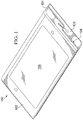
- FIGS. 1 and 2 present an illustrative apparatus 100 that accords with certain of the teachings described herein.
- this apparatus 100 comprises a portable electronic device such as, but not limited to, a portable communications device.
- a portable electronic device such as, but not limited to, a portable communications device.
- the present teachings are not especially limited in such regards and that this example is intended to serve an illustrative purpose rather than as a suggestion regarding any limitations in these regards.
- This apparatus 100 includes a first housing 101 having an upper surface 102 and a second housing 103 that also has an upper surface 104.
- the first housing 101 includes a display 105 (such as, but not limited to, a touch-screen display of choice).
- the first housing 101 and the second housing 103 share a substantially same footprint and, to some extent, have form factors that are mirror images to one another.
- the upper surface 102 of the first housing 101 is substantially planar in this example.
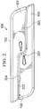
- the upper surface 104 of the second housing 103 includes a non-planar portion 201 (shown with particular clarity in FIG. 2 ).
- this non-planar portion 201 comprises a sloped step that connects a first planar portion 202 to a second planar portion 203.
- the bottom surface 204 of the first housing 101 at least substantially conforms to the upper surface 104 of the second housing 103 (including the non-planar portion 201 of that upper surface 104). So configured, the bottom surface 204 of the first housing 101 interlocks with the upper surface 104 (including the non-planar portion 201) of the second housing 103.
- the expression "interlock” will be understood to include both a locking engagement as well as a non-locking mating/meeting of opposing surfaces that are not wholly planar.
- FIGS. 1 and 2 depict the first housing 101 and the second housing 103 in a stacked configuration that comprises a first position.
- the first housing 101 is disposed atop the second housing 103. So configured, the apparatus 100 has a minimized footprint.
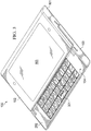
- the present teachings provide as well, however, for at least a second position as illustrated in FIGS. 3 and 4 .
- the first housing 101 and the second housing 103 are disposed adjacent and at least substantially coplanar to one another.
- the upper surface 102 of the first housing 101 is disposed at least substantially coplanar to a portion 202 of the upper surface 104 of the second housing 103.
- the upper surface 104 of the second housing 103 conforms to and interlocks with the bottom surface 204 of the first housing 101.
- the planar and curved surfaces of both the upper surface 104 and the bottom surface 204 meet in a substantially conformal manner.
- the apparatus 100 has a larger footprint as compared to the first position (though a reduced profile).
- This larger footprint can readily accommodate, for example, a physical keyboard 301 as comprises a part of the second housing 103 (as shown in FIG. 3 ). So configured, the apparatus 100 presents the keyboard 301 below but adjacent to the display 105 to thereby comport with ordinary user expectations in these regards.
- the physical keyboard 301 can comprise any of a wide variety of keyboard designs (both with respect to keyboard layout as well as actuation mechanisms). These teachings will also accommodate, if desired, using a second display (not shown) to present a virtual keyboard (not shown). Such keyboard designs and alternatives comprise a well understood area of prior art endeavor. As the present teachings are not particularly sensitive to any specific choices in these regards, further elaboration regarding the details of such keyboard will not be provided here for the sake of brevity.
- FIGS. 5 , 6, and 7 illustrate at least one approach to facilitating relative movement between the first housing 101 and the second housing 103 to move these housings 101 and 103 between the first position and the second position described above.
- each lateral side of each housing 101 and 103 includes a cam (in this example, a wedge-shaped cam that comprises, in this particular example, a pear-shaped cam having a rounded bottom) that operates in conjunction with a link 501 that itself includes a first slot 502 and a second slot 503 that are disposed at least substantially collinear to one another.
- the first housing 101 includes (on one side as illustrated) a first cam 504 and the second housing 103 includes (on one side as illustrated) a second such cam 505.
- these two cams 504 and 505 are disposed at least substantially longitudinally parallel to one another but are also disposed offset to one another by a non-zero distance "Y.”
- the precise dimensions of this offset "Y" will of course vary with respect to the relative sizes of the other displayed components.
- FIG. 5 specifically depicts the first housing 101 and the second housing 103 in the aforementioned first position with respect to one another. Accordingly, the first housing 101 is stacked atop the second housing 103.
- the first slot 502 of the link 501 receives the first cam 504 while the second slot 503 of the link 501 receives the second cam 505.
- the two cams 504 and 505 are disposed relatively closer to one another (in fact, as proximal to one another as this configuration will permit) and also more or less at the internally-directed end of their respective slot 502 or 503.
- the link 501 is disposed at an acute angle with respect to the housings 101 and 103 and one side of each of the cams 504 and 505 is parallel to and contacts a side of a respective one of the slots 502 and 503. It may be noted as well that, in this particular example, there are no biasing members (such as springs or the like) to urge the link in any particular direction.
- a user can urge the apparatus 100 towards the aforementioned second position by urging the first housing 101 to the rear and/or by urging the second housing 103 towards the front.
- the two housings 101 and 103 slide with respect to one another as shown in FIG. 6 .
- the two cams 504 and 505 move further apart from one another and the link 501 effectively pivots about the larger, rounded end of one or both cams 504 and 505.
- the link 501 permits the described sliding movement but will not accommodate, for example, a more significant vertical separation of the two housings 101 and 103. Instead, the pear-shaped form factor of the cams 504 and 505 will cooperate with the shape and length of the slots 502 and 503 to limit such movement. Accordingly, this simple arrangement will largely constrain movement of the two housings 101 and 103 to a specific path between the first position and the second position as well as to those two positions themselves.
- each such cam 504 and 505 can have a corresponding tab 801 to facilitate attaching the cam 504 and 505 to an interior surface of a respective housing 101 and 103 (using, for example, a threaded attachment member, a brad, a latching mechanism, a friction fit, or some other attachment approach of choice).
- the cams 504 and 505 can be oriented laterally outwardly of the housings 101 and 103 and can have an outer portion that fits, for example, into a corresponding hole 802 in the side of the housing.
- the link 501 can be (loosely) captivated by a corresponding cam 504 or 505 between the aforementioned tab 801 and the side wall of the respective housing.
- link-and-cam assembly can be provided on both opposing sides of the apparatus 100.
- a first link is disposed on one side of the apparatus 100 that engages a first cam (that comprises a part of the first housing 101) and a second cam (that comprises a part of the second housing 103) and a second (at least substantially identical) link is disposed on the opposite side of the apparatus 100 that engages a third cam (that comprises a part of the first housing 101) and a fourth cam (that comprises a part of the second housing 103).
- link-and-cam assemblies can act as described above to both help to guide relative movement between the two housings 101 and 103 back and forth between the first and second positions.
- a user can conveniently and with considerable assurance manipulate the housings 101 and 103 to expose and deploy the keyboard 301 as desired and to similarly stow that keyboard 301 as needed.
- These teachings facilitate such movement using only a very few parts and via a simple arrangement that is unlikely to present operational or maintenance challenges. Notwithstanding that simplicity, however, the movement of the housings 101 and 103 is nevertheless both intuitive and sure, firm and unambiguous.
- an exemplary portable electronic device includes a control circuit 902 that controls the overall operation of the portable electronic device.
- the communication subsystem receives messages from and sends messages to a wireless network 950.
- the wireless network 950 may be any type of wireless network, including, but not limited to, data wireless networks, voice wireless networks, and networks that support both voice and data communications.
- a power source 942 such as one or more rechargeable batteries or a port to an external power supply, powers the electronic device.
- the control circuit 902 may also interact with an accelerometer 936 that may be utilized to detect direction of gravitational forces or gravity-induced reaction forces.
- the control circuit 902 interacts with other elements, such as a Random Access Memory (RAM) 908, a memory 910, the aforementioned display 105 along with a touch-sensitive overlay 914 operably coupled to an electronic controller 916 that together comprise a touch-sensitive display 918, an auxiliary input/output (I/O) subsystem 924, a data port 926, a speaker 928, a microphone 930, and a short-range communication subsystem 932.
- RAM Random Access Memory
- I/O auxiliary input/output
- One or more user interfaces are provided including the aforementioned keyboard 301. Input via a graphical user interface can also be provided via the touch-sensitive overlay 914.
- the control circuit 902 interacts with the touch-sensitive overlay 914 via the electronic controller 916.
- Information such as text, characters, symbols, images, icons, and other items that may be displayed or rendered on a portable electronic device, is displayed on the display 105 via the control circuit 902.
- the portable electronic device may utilize a Subscriber Identity Module or a Removable User Identity Module (SIM/RUIM) card 938 for communication with a network, such as the wireless network 950.
- SIM/RUIM Removable User Identity Module
- user identification information may be programmed into the memory 910.
- the portable electronic device in this example also includes an operating system 946 and software programs, applications, or components 948 that are executed by the control circuit 902 and are typically stored in a persistent, updatable store such as the memory 910. Additional applications or programs may be loaded onto the portable electronic device through the wireless network 950, the auxiliary I/O subsystem 924, the data port 926, the short-range communications subsystem 932, or any other suitable subsystem 934.
- the memory 910 may comprise a non-transitory storage media that stores executable code, when executed, causes one or more of functions or actions as described herein.
Description
- The present disclosure relates generally to multi-housing apparatuses and more particularly to apparatuses having housings that move relative to one another.
- Electronic devices, including portable electronic devices, have gained widespread use and may provide a variety of functions including, for example, telephonic, electronic messaging and other personal information manager (PIM) application functions. Portable electronic devices include, for example, several types of mobile stations such as simple cellular telephones, smart telephones, wireless personal digital assistants (PDAs), and laptop computers with wireless 802.11 or Bluetooth capabilities.
- Portable electronic devices such as PDAs or smart telephones are generally intended for handheld use and ease of portability. Smaller devices are generally desirable for portability. A touch-sensitive display, also known as a touchscreen display, is particularly useful on handheld devices, which are small and have limited space for user input and output. The information displayed on the touch-sensitive displays may be modified depending on the functions and operations being performed. With continued demand for decreased size of portable electronic devices, touch-sensitive displays continue to decrease in size.
- That said, physical keyboards (as versus a virtual keyboard presented on a touch-sensitive display) are also in demand. Many people find physical keyboards to be easier and/or more accurate to use than a virtual keyboard. Providing a given device with both a touch-sensitive display and a physical keyboard, however, often forces a compromise with respect to the overall size of the apparatus and/or the size of one or both of the display and the keyboard. One design approach separates the device into two housings with one housing having the display and the other housing having the physical keyboard. While a helpful approach in many instances, again, many compromises regarding the relative size of these components and/or ease of use are often required. In addition, many such approaches tend to be mechanically and/or electrically complicated, fragile, and/or expensive to implement.
-
TW M 422 001 -
EP2421229 is directed to a mobile device includes a first housing, a second housing, and a hinge assembly rotatably coupling the first housing to the second housing and enabling movement of the device between an open configuration and a closed configuration. When the device is in the open configuration, the first housing is planar with the second housing. -
US2001027121 discloses a personal electronic device comprising a PDA portion and a cellular transceiver portion and a slide hinge allowing the cellular transceiver portion to slide past the PDA portion so that both the cellular transceiver and the PDA are accessible in an open position, and the cellular transceiver portion completely covers the PDA portion when in a closed position. A knob or button is used to secure the position of the slide hinge. -
-
FIG. 1 is a perspective view in accordance with the disclosure. -
FIG. 2 is a side-elevational view in accordance with the disclosure. -
FIG. 3 is a perspective view in accordance with the disclosure. -
FIG. 4 is a side-elevational view in accordance with the disclosure. -
FIG. 5 is a side-elevational partially-phantom view in accordance with the disclosure. -
FIG. 6 is a side-elevational view in accordance with the disclosure. -
FIG. 7 is a side-elevational partially-phantom view in accordance with the disclosure. -
FIG. 8 is an exploded perspective view in accordance with the disclosure. -
FIG. 9 is a block diagram in accordance with the disclosure. - The following describes an apparatus having a first housing and a second housing. Both housings have a corresponding upper surface and at least one cam. A link is configured and disposed to slidingly engage these cams. So configured, the first housing is movable with respect to the second housing between a first position and a second position. The first position comprises a stacked configuration with the first housing disposed atop the second housing. The second position comprises a deployed configuration with the upper surface of the first housing disposed at least substantially coplanar to a portion of the upper surface of the second housing.
- By one approach the first housing includes a display (including but not limited to a touch-screen display) and the second housing includes a keyboard (including but not limited to a physical keyboard. So configured, the display can be used sans the keyboard when the housings are deployed in the first position and the display can be used in conjunction with the keyboard when the housings are deployed in the second position.
- By one approach the aforementioned link includes a pair of slots disposed therethrough. These slots can be, if desired, substantially collinear to one another. The cams, in turn, can be at least substantially pear shaped and can be disposed offset to one another and substantially longitudinally parallel to one another as well. Also if desired, such cams can be disposed on interior surfaces of both housings, and on both sides of the housings as well. So configured, such a link can be included on both sides of the apparatus to thereby provide smooth, balanced, sturdy movement of the two housings with respect to one another.
- According to the invention, the upper surface of the second housing includes a non-planar portion (such that this upper surface comprises, in total, a non-planar upper surface). The bottom surface of the first housing, in turn, conforms to that non-planar portion such that the bottom surface of the first housing interlocks with the non-planar portion of the second housing's upper surface. So configured, the two housings (in the second position) effectively form a seemingly integral device that can present both a display and a keyboard in a unitary and substantially coplanar manner.
- These teachings permit a pair of housings to be readily moved with respect to one another in a consistent, smooth, intuitive, and guided manner. The supported movement itself can be relatively complex notwithstanding the limited number of moving parts and thereby contribute to a choice of very useful housing configurations. These teachings are highly flexible in practice and will accommodate a variety of housing shapes and sizes.
- For simplicity and clarity of illustration, reference numerals may be repeated among the figures to indicate corresponding or analogous elements. Numerous details are set forth to provide an understanding of the embodiments described herein. The embodiments may be practiced without these details. In other instances, well-known methods, procedures, and components have not been described in detail to avoid obscuring the embodiments described. The description is not to be considered as limited to the scope of the embodiments described herein. The invention is defined by the appended claims.
-
FIGS. 1 and2 present anillustrative apparatus 100 that accords with certain of the teachings described herein. For the sake of illustration it will be presumed that thisapparatus 100 comprises a portable electronic device such as, but not limited to, a portable communications device. It will be understood, however, that the present teachings are not especially limited in such regards and that this example is intended to serve an illustrative purpose rather than as a suggestion regarding any limitations in these regards. - This
apparatus 100 includes afirst housing 101 having anupper surface 102 and asecond housing 103 that also has anupper surface 104. In this illustrative example thefirst housing 101 includes a display 105 (such as, but not limited to, a touch-screen display of choice). Also in this example thefirst housing 101 and thesecond housing 103 share a substantially same footprint and, to some extent, have form factors that are mirror images to one another. - The
upper surface 102 of thefirst housing 101 is substantially planar in this example. Theupper surface 104 of thesecond housing 103, however, includes a non-planar portion 201 (shown with particular clarity inFIG. 2 ). In this example thisnon-planar portion 201 comprises a sloped step that connects a firstplanar portion 202 to a secondplanar portion 203. Thebottom surface 204 of thefirst housing 101, in turn, at least substantially conforms to theupper surface 104 of the second housing 103 (including thenon-planar portion 201 of that upper surface 104). So configured, thebottom surface 204 of thefirst housing 101 interlocks with the upper surface 104 (including the non-planar portion 201) of thesecond housing 103. (As used herein, the expression "interlock" will be understood to include both a locking engagement as well as a non-locking mating/meeting of opposing surfaces that are not wholly planar.) -
FIGS. 1 and2 depict thefirst housing 101 and thesecond housing 103 in a stacked configuration that comprises a first position. In particular, thefirst housing 101 is disposed atop thesecond housing 103. So configured, theapparatus 100 has a minimized footprint. The present teachings provide as well, however, for at least a second position as illustrated inFIGS. 3 and4 . - As shown in these figures, in the second position (which comprises a deployed position in this example) the
first housing 101 and thesecond housing 103 are disposed adjacent and at least substantially coplanar to one another. In particular, theupper surface 102 of thefirst housing 101 is disposed at least substantially coplanar to aportion 202 of theupper surface 104 of thesecond housing 103. It will be noted that again in this illustrative example theupper surface 104 of thesecond housing 103 conforms to and interlocks with thebottom surface 204 of thefirst housing 101. In particular, the planar and curved surfaces of both theupper surface 104 and thebottom surface 204 meet in a substantially conformal manner. - In this second position the
apparatus 100 has a larger footprint as compared to the first position (though a reduced profile). This larger footprint can readily accommodate, for example, aphysical keyboard 301 as comprises a part of the second housing 103 (as shown inFIG. 3 ). So configured, theapparatus 100 presents thekeyboard 301 below but adjacent to thedisplay 105 to thereby comport with ordinary user expectations in these regards. - The
physical keyboard 301 can comprise any of a wide variety of keyboard designs (both with respect to keyboard layout as well as actuation mechanisms). These teachings will also accommodate, if desired, using a second display (not shown) to present a virtual keyboard (not shown). Such keyboard designs and alternatives comprise a well understood area of prior art endeavor. As the present teachings are not particularly sensitive to any specific choices in these regards, further elaboration regarding the details of such keyboard will not be provided here for the sake of brevity. -
FIGS. 5 ,6, and 7 illustrate at least one approach to facilitating relative movement between thefirst housing 101 and thesecond housing 103 to move thesehousings housing link 501 that itself includes afirst slot 502 and asecond slot 503 that are disposed at least substantially collinear to one another. In particular, thefirst housing 101 includes (on one side as illustrated) afirst cam 504 and thesecond housing 103 includes (on one side as illustrated) a secondsuch cam 505. In this illustrative example these twocams -
FIG. 5 specifically depicts thefirst housing 101 and thesecond housing 103 in the aforementioned first position with respect to one another. Accordingly, thefirst housing 101 is stacked atop thesecond housing 103. Thefirst slot 502 of thelink 501 receives thefirst cam 504 while thesecond slot 503 of thelink 501 receives thesecond cam 505. - When the
housings cams respective slot link 501 is disposed at an acute angle with respect to thehousings cams slots - A user can urge the
apparatus 100 towards the aforementioned second position by urging thefirst housing 101 to the rear and/or by urging thesecond housing 103 towards the front. When such urging occurs the twohousings FIG. 6 . As this movement occurs, the twocams link 501 effectively pivots about the larger, rounded end of one or bothcams - So configured, the
link 501 permits the described sliding movement but will not accommodate, for example, a more significant vertical separation of the twohousings cams slots housings - Eventually, and as suggested by the illustration provided at
FIG. 7 , thecams respective slot housings housings - Referring to
FIG. 8 , by one approach theaforementioned cams respective housings first cam 504 would be disposed within an interior portion of thefirst housing 101 and thesecond cam 505 would be disposed within an interior portion of thesecond housing 103. By one approach, eachsuch cam corresponding tab 801 to facilitate attaching thecam respective housing 101 and 103 (using, for example, a threaded attachment member, a brad, a latching mechanism, a friction fit, or some other attachment approach of choice). - By one approach the
cams housings corresponding hole 802 in the side of the housing. Using the approach, thelink 501 can be (loosely) captivated by a correspondingcam aforementioned tab 801 and the side wall of the respective housing. - For some application settings it may be sufficient to provide only one such link-and-cam assembly. If desired, however, such a link-and-cam assembly can be provided on both opposing sides of the
apparatus 100. In this case, and by way of example, a first link is disposed on one side of theapparatus 100 that engages a first cam (that comprises a part of the first housing 101) and a second cam (that comprises a part of the second housing 103) and a second (at least substantially identical) link is disposed on the opposite side of theapparatus 100 that engages a third cam (that comprises a part of the first housing 101) and a fourth cam (that comprises a part of the second housing 103). So configured, link-and-cam assemblies can act as described above to both help to guide relative movement between the twohousings - So configured, a user can conveniently and with considerable assurance manipulate the
housings keyboard 301 as desired and to similarly stow thatkeyboard 301 as needed. These teachings facilitate such movement using only a very few parts and via a simple arrangement that is unlikely to present operational or maintenance challenges. Notwithstanding that simplicity, however, the movement of thehousings - As suggested above, these teachings can be applied in conjunction with any of a wide variety of apparatuses including a portable electronics device such as a so-called smartphone or tablet-styled wireless computer. Referring to
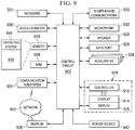
FIG. 9 , an exemplary portable electronic device includes acontrol circuit 902 that controls the overall operation of the portable electronic device. - Communication functions, including data and voice communications, are performed through a
communication subsystem 904. The communication subsystem receives messages from and sends messages to awireless network 950. Thewireless network 950 may be any type of wireless network, including, but not limited to, data wireless networks, voice wireless networks, and networks that support both voice and data communications. - A
power source 942, such as one or more rechargeable batteries or a port to an external power supply, powers the electronic device. In this illustrative example, thecontrol circuit 902 may also interact with anaccelerometer 936 that may be utilized to detect direction of gravitational forces or gravity-induced reaction forces. - The
control circuit 902 interacts with other elements, such as a Random Access Memory (RAM) 908, amemory 910, theaforementioned display 105 along with a touch-sensitive overlay 914 operably coupled to anelectronic controller 916 that together comprise a touch-sensitive display 918, an auxiliary input/output (I/O)subsystem 924, adata port 926, aspeaker 928, amicrophone 930, and a short-range communication subsystem 932. - One or more user interfaces are provided including the
aforementioned keyboard 301. Input via a graphical user interface can also be provided via the touch-sensitive overlay 914. Thecontrol circuit 902 interacts with the touch-sensitive overlay 914 via theelectronic controller 916. Information, such as text, characters, symbols, images, icons, and other items that may be displayed or rendered on a portable electronic device, is displayed on thedisplay 105 via thecontrol circuit 902. - To identify a subscriber for network access, the portable electronic device may utilize a Subscriber Identity Module or a Removable User Identity Module (SIM/RUIM)
card 938 for communication with a network, such as thewireless network 950. Alternatively, user identification information may be programmed into thememory 910. - The portable electronic device in this example also includes an
operating system 946 and software programs, applications, orcomponents 948 that are executed by thecontrol circuit 902 and are typically stored in a persistent, updatable store such as thememory 910. Additional applications or programs may be loaded onto the portable electronic device through thewireless network 950, the auxiliary I/O subsystem 924, thedata port 926, the short-range communications subsystem 932, or any other suitable subsystem 934. Thememory 910 may comprise a non-transitory storage media that stores executable code, when executed, causes one or more of functions or actions as described herein. - The present disclosure may be embodied in other specific forms without departing from its essential characteristics. The described embodiments are to be considered in all respects only as illustrative and not restrictive. The scope of the disclosure is, therefore, indicated by the appended claims rather than by the foregoing description.
Claims (10)
- An apparatus (100) comprising:a first housing (101) having an upper surface (102), a bottom surface (204), and at least a first cam (504);a second housing (103) having an upper surface (104) and having at least a second cam (505);a link (501) configured and disposed to slidingly engage the first cam and the second cam;wherein the first cam, the second cam, and the link are configured such that the first housing is movable with respect to the second housing between a first position and a second position, wherein:each of the bottom surface (204) of the first housing (101) and the upper surface (104) of the second housing (103) comprises a first planar portion, a second planar portion and a non-planar portion (201) for connecting said first and second planar portions,the first position comprises a stacked configuration with the first housing disposed atop the second housing and the bottom surface (204) of the first housing (101) adjacent to the upper surface (104) of the second housing (103); andthe second position comprises a deployed configuration with the upper surface (102) of the first housing (101) disposed at least substantially coplanar to the first planar portion (202) of the upper surface (104) of the second housing (103), wherein the bottom surface (204) of the first housing (101) and the upper surface (104) of the second housing (103) conform to one another and interlock with one another in the stacked configuration and in the deployed configuration.
- The apparatus of claim 1 wherein the first housing includes a display (105) and the second housing includes a keyboard (301).
- The apparatus of claim 1 wherein the link includes a first slot (502) that receives the first cam and a second slot (503) that receives the second cam.
- The apparatus of claim 3 wherein the first slot is disposed at least substantially collinear with respect to the second slot.
- The apparatus of claim 1 wherein the first cam and the second cam each comprise a pear-shaped cam.
- The apparatus of claim 1 wherein the first cam and the second cam are disposed offset and at least substantially longitudinally parallel to one another.
- The apparatus of claim 1 wherein the first cam is disposed within an interior portion of the first housing and the second cam is disposed within an interior portion of the second housing.
- The apparatus of claim 1 wherein the first cam is disposed on a first side of the first housing and the second cam is disposed on a first side of the second housing, and wherein:the first housing includes a third cam;the second housing includes a fourth cam;a second link configured and disposed to slidingly engage the third cam and the fourth cam;wherein the third cam, the fourth cam, and the second link are also configured such that the first housing is movable with respect to the second housing between the first position and the second position.
- The apparatus of claim 8 wherein the first cam and the third cam are disposed on opposing sides of the first housing and the second cam and the fourth cam are disposed on opposing sides of the second housing.
- The apparatus of claim 1 wherein the first planar portion of the bottom surface (204) of the first housing (101) is disposed atop the second planar portion (203) of the upper surface (104) of the second housing (103) in the second position.
Applications Claiming Priority (2)
| Application Number | Priority Date | Filing Date | Title |
|---|---|---|---|
| US201261666439P | 2012-06-29 | 2012-06-29 | |
| US13/555,792 US8891236B2 (en) | 2012-06-29 | 2012-07-23 | Housings that move using a link that slidingly engages cams |
Publications (3)
| Publication Number | Publication Date |
|---|---|
| EP2680100A2 EP2680100A2 (en) | 2014-01-01 |
| EP2680100A3 EP2680100A3 (en) | 2017-05-17 |
| EP2680100B1 true EP2680100B1 (en) | 2021-02-17 |
Family
ID=48747934
Family Applications (1)
| Application Number | Title | Priority Date | Filing Date |
|---|---|---|---|
| EP13173814.8A Active EP2680100B1 (en) | 2012-06-29 | 2013-06-26 | Housings that move using a link that slidingly engages cams |
Country Status (2)
| Country | Link |
|---|---|
| US (1) | US8891236B2 (en) |
| EP (1) | EP2680100B1 (en) |
Families Citing this family (1)
| Publication number | Priority date | Publication date | Assignee | Title |
|---|---|---|---|---|
| PT3018497T (en) * | 2014-11-10 | 2022-05-17 | Schreder | Method for detecting earthquakes and locating epicentres by means of a network of lights. |
Family Cites Families (8)
| Publication number | Priority date | Publication date | Assignee | Title |
|---|---|---|---|---|
| US6542721B2 (en) * | 1999-10-11 | 2003-04-01 | Peter V. Boesen | Cellular telephone, personal digital assistant and pager unit |
| TWI278216B (en) * | 2005-11-03 | 2007-04-01 | Benq Corp | Mobile device |
| KR101463819B1 (en) * | 2008-05-14 | 2014-12-04 | 엘지전자 주식회사 | Portable terminal |
| US8660621B2 (en) * | 2010-08-20 | 2014-02-25 | Blackberry Limited | Mobile phone |
| US8982542B2 (en) * | 2010-11-17 | 2015-03-17 | Microsoft Technology Licensing, Llc | Hinge mechanism for mobile electronic device |
| KR101750117B1 (en) * | 2011-01-10 | 2017-06-22 | 삼성전자주식회사 | Cradling apparatus for portable communication device |
| JP5039216B2 (en) * | 2011-02-24 | 2012-10-03 | 株式会社東芝 | Electronics |
| TWM422001U (en) * | 2011-07-13 | 2012-02-01 | Quanta Comp Inc | Dual-axis hinge structure and electric device having the same |
-
2012
- 2012-07-23 US US13/555,792 patent/US8891236B2/en active Active
-
2013
- 2013-06-26 EP EP13173814.8A patent/EP2680100B1/en active Active
Non-Patent Citations (1)
| Title |
|---|
| None * |
Also Published As
| Publication number | Publication date |
|---|---|
| EP2680100A2 (en) | 2014-01-01 |
| US8891236B2 (en) | 2014-11-18 |
| EP2680100A3 (en) | 2017-05-17 |
| US20140001936A1 (en) | 2014-01-02 |
Similar Documents
| Publication | Publication Date | Title |
|---|---|---|
| US9013864B2 (en) | Support for a flexible display | |
| US8971032B2 (en) | Support for a flexible display | |
| US8537542B2 (en) | Electronic device | |
| EP2728434B1 (en) | Support for a flexible display | |
| US20140123436A1 (en) | Support for a flexible display | |
| EP2728433A1 (en) | Support for a flexible display | |
| EP2728432A1 (en) | Support for a flexible display | |
| EP2012506A2 (en) | Slide hinge module and slide type equipment utilizing the same | |
| KR101927201B1 (en) | Portable terminal with support plate | |
| KR20140108313A (en) | Mobile computing device, apparatus and system | |
| EP2680100B1 (en) | Housings that move using a link that slidingly engages cams | |
| US8724317B2 (en) | Apparatus pertaining to a deployable keyboard and corresponding bottom surface | |
| EP2687940B1 (en) | Apparatus pertaining to a keyboard comprised of physically-discrete hinged segments | |
| EP2680098B1 (en) | Apparatus pertaining to a deployable keyboard and corresponding bottom surface | |
| EP2635005B1 (en) | A storable keyboard having variable angular orientations | |
| US8804318B2 (en) | Storable keyboard having variable angular orientations | |
| CA2828860A1 (en) | Support for a flexible display | |
| EP2674830A1 (en) | A storable keyboard having a pivoting cover | |
| US8611973B2 (en) | Slidable portable electronic device with keypad portion adapted for covering display | |
| EP2498478B1 (en) | Slidable portable electronic device with keypad portion adapted for covering display | |
| US20220075425A1 (en) | Storage medium tray structure and electronic device comprising same | |
| US9210240B2 (en) | Portable slidable electronic device having a dynamic flex alignment scheme and methods of assembling same | |
| US8830667B2 (en) | Storable keyboard having a pivoting cover | |
| EP2688271B1 (en) | Apparatus pertaining to hinged rows of keycaps | |
| CN113741854A (en) | Multi-computer management device |
Legal Events
| Date | Code | Title | Description |
|---|---|---|---|
| PUAI | Public reference made under article 153(3) epc to a published international application that has entered the european phase |
Free format text: ORIGINAL CODE: 0009012 |
|
| 17P | Request for examination filed |
Effective date: 20130626 |
|
| AK | Designated contracting states |
Kind code of ref document: A2 Designated state(s): AL AT BE BG CH CY CZ DE DK EE ES FI FR GB GR HR HU IE IS IT LI LT LU LV MC MK MT NL NO PL PT RO RS SE SI SK SM TR |
|
| AX | Request for extension of the european patent |
Extension state: BA ME |
|
| PUAL | Search report despatched |
Free format text: ORIGINAL CODE: 0009013 |
|
| AK | Designated contracting states |
Kind code of ref document: A3 Designated state(s): AL AT BE BG CH CY CZ DE DK EE ES FI FR GB GR HR HU IE IS IT LI LT LU LV MC MK MT NL NO PL PT RO RS SE SI SK SM TR |
|
| AX | Request for extension of the european patent |
Extension state: BA ME |
|
| RIC1 | Information provided on ipc code assigned before grant |
Ipc: G06F 1/16 20060101AFI20170411BHEP |
|
| STAA | Information on the status of an ep patent application or granted ep patent |
Free format text: STATUS: EXAMINATION IS IN PROGRESS |
|
| 17Q | First examination report despatched |
Effective date: 20181012 |
|
| GRAP | Despatch of communication of intention to grant a patent |
Free format text: ORIGINAL CODE: EPIDOSNIGR1 |
|
| STAA | Information on the status of an ep patent application or granted ep patent |
Free format text: STATUS: GRANT OF PATENT IS INTENDED |
|
| INTG | Intention to grant announced |
Effective date: 20200917 |
|
| GRAS | Grant fee paid |
Free format text: ORIGINAL CODE: EPIDOSNIGR3 |
|
| GRAA | (expected) grant |
Free format text: ORIGINAL CODE: 0009210 |
|
| STAA | Information on the status of an ep patent application or granted ep patent |
Free format text: STATUS: THE PATENT HAS BEEN GRANTED |
|
| AK | Designated contracting states |
Kind code of ref document: B1 Designated state(s): AL AT BE BG CH CY CZ DE DK EE ES FI FR GB GR HR HU IE IS IT LI LT LU LV MC MK MT NL NO PL PT RO RS SE SI SK SM TR |
|
| REG | Reference to a national code |
Ref country code: GB Ref legal event code: FG4D |
|
| REG | Reference to a national code |
Ref country code: CH Ref legal event code: EP |
|
| REG | Reference to a national code |
Ref country code: DE Ref legal event code: R096 Ref document number: 602013075624 Country of ref document: DE |
|
| REG | Reference to a national code |
Ref country code: AT Ref legal event code: REF Ref document number: 1362306 Country of ref document: AT Kind code of ref document: T Effective date: 20210315 |
|
| REG | Reference to a national code |
Ref country code: IE Ref legal event code: FG4D |
|
| REG | Reference to a national code |
Ref country code: LT Ref legal event code: MG9D |
|
| REG | Reference to a national code |
Ref country code: NL Ref legal event code: MP Effective date: 20210217 |
|
| PG25 | Lapsed in a contracting state [announced via postgrant information from national office to epo] |
Ref country code: FI Free format text: LAPSE BECAUSE OF FAILURE TO SUBMIT A TRANSLATION OF THE DESCRIPTION OR TO PAY THE FEE WITHIN THE PRESCRIBED TIME-LIMIT Effective date: 20210217 Ref country code: HR Free format text: LAPSE BECAUSE OF FAILURE TO SUBMIT A TRANSLATION OF THE DESCRIPTION OR TO PAY THE FEE WITHIN THE PRESCRIBED TIME-LIMIT Effective date: 20210217 Ref country code: GR Free format text: LAPSE BECAUSE OF FAILURE TO SUBMIT A TRANSLATION OF THE DESCRIPTION OR TO PAY THE FEE WITHIN THE PRESCRIBED TIME-LIMIT Effective date: 20210518 Ref country code: LT Free format text: LAPSE BECAUSE OF FAILURE TO SUBMIT A TRANSLATION OF THE DESCRIPTION OR TO PAY THE FEE WITHIN THE PRESCRIBED TIME-LIMIT Effective date: 20210217 Ref country code: PT Free format text: LAPSE BECAUSE OF FAILURE TO SUBMIT A TRANSLATION OF THE DESCRIPTION OR TO PAY THE FEE WITHIN THE PRESCRIBED TIME-LIMIT Effective date: 20210617 Ref country code: NO Free format text: LAPSE BECAUSE OF FAILURE TO SUBMIT A TRANSLATION OF THE DESCRIPTION OR TO PAY THE FEE WITHIN THE PRESCRIBED TIME-LIMIT Effective date: 20210517 Ref country code: BG Free format text: LAPSE BECAUSE OF FAILURE TO SUBMIT A TRANSLATION OF THE DESCRIPTION OR TO PAY THE FEE WITHIN THE PRESCRIBED TIME-LIMIT Effective date: 20210517 |
|
| REG | Reference to a national code |
Ref country code: AT Ref legal event code: MK05 Ref document number: 1362306 Country of ref document: AT Kind code of ref document: T Effective date: 20210217 |
|
| PG25 | Lapsed in a contracting state [announced via postgrant information from national office to epo] |
Ref country code: RS Free format text: LAPSE BECAUSE OF FAILURE TO SUBMIT A TRANSLATION OF THE DESCRIPTION OR TO PAY THE FEE WITHIN THE PRESCRIBED TIME-LIMIT Effective date: 20210217 Ref country code: NL Free format text: LAPSE BECAUSE OF FAILURE TO SUBMIT A TRANSLATION OF THE DESCRIPTION OR TO PAY THE FEE WITHIN THE PRESCRIBED TIME-LIMIT Effective date: 20210217 Ref country code: PL Free format text: LAPSE BECAUSE OF FAILURE TO SUBMIT A TRANSLATION OF THE DESCRIPTION OR TO PAY THE FEE WITHIN THE PRESCRIBED TIME-LIMIT Effective date: 20210217 Ref country code: LV Free format text: LAPSE BECAUSE OF FAILURE TO SUBMIT A TRANSLATION OF THE DESCRIPTION OR TO PAY THE FEE WITHIN THE PRESCRIBED TIME-LIMIT Effective date: 20210217 Ref country code: SE Free format text: LAPSE BECAUSE OF FAILURE TO SUBMIT A TRANSLATION OF THE DESCRIPTION OR TO PAY THE FEE WITHIN THE PRESCRIBED TIME-LIMIT Effective date: 20210217 |
|
| PG25 | Lapsed in a contracting state [announced via postgrant information from national office to epo] |
Ref country code: IS Free format text: LAPSE BECAUSE OF FAILURE TO SUBMIT A TRANSLATION OF THE DESCRIPTION OR TO PAY THE FEE WITHIN THE PRESCRIBED TIME-LIMIT Effective date: 20210617 |
|
| PG25 | Lapsed in a contracting state [announced via postgrant information from national office to epo] |
Ref country code: EE Free format text: LAPSE BECAUSE OF FAILURE TO SUBMIT A TRANSLATION OF THE DESCRIPTION OR TO PAY THE FEE WITHIN THE PRESCRIBED TIME-LIMIT Effective date: 20210217 Ref country code: CZ Free format text: LAPSE BECAUSE OF FAILURE TO SUBMIT A TRANSLATION OF THE DESCRIPTION OR TO PAY THE FEE WITHIN THE PRESCRIBED TIME-LIMIT Effective date: 20210217 Ref country code: AT Free format text: LAPSE BECAUSE OF FAILURE TO SUBMIT A TRANSLATION OF THE DESCRIPTION OR TO PAY THE FEE WITHIN THE PRESCRIBED TIME-LIMIT Effective date: 20210217 Ref country code: SM Free format text: LAPSE BECAUSE OF FAILURE TO SUBMIT A TRANSLATION OF THE DESCRIPTION OR TO PAY THE FEE WITHIN THE PRESCRIBED TIME-LIMIT Effective date: 20210217 |
|
| REG | Reference to a national code |
Ref country code: DE Ref legal event code: R097 Ref document number: 602013075624 Country of ref document: DE |
|
| PG25 | Lapsed in a contracting state [announced via postgrant information from national office to epo] |
Ref country code: RO Free format text: LAPSE BECAUSE OF FAILURE TO SUBMIT A TRANSLATION OF THE DESCRIPTION OR TO PAY THE FEE WITHIN THE PRESCRIBED TIME-LIMIT Effective date: 20210217 Ref country code: SK Free format text: LAPSE BECAUSE OF FAILURE TO SUBMIT A TRANSLATION OF THE DESCRIPTION OR TO PAY THE FEE WITHIN THE PRESCRIBED TIME-LIMIT Effective date: 20210217 Ref country code: DK Free format text: LAPSE BECAUSE OF FAILURE TO SUBMIT A TRANSLATION OF THE DESCRIPTION OR TO PAY THE FEE WITHIN THE PRESCRIBED TIME-LIMIT Effective date: 20210217 Ref country code: ES Free format text: LAPSE BECAUSE OF FAILURE TO SUBMIT A TRANSLATION OF THE DESCRIPTION OR TO PAY THE FEE WITHIN THE PRESCRIBED TIME-LIMIT Effective date: 20210217 |
|
| PLBE | No opposition filed within time limit |
Free format text: ORIGINAL CODE: 0009261 |
|
| STAA | Information on the status of an ep patent application or granted ep patent |
Free format text: STATUS: NO OPPOSITION FILED WITHIN TIME LIMIT |
|
| 26N | No opposition filed |
Effective date: 20211118 |
|
| PG25 | Lapsed in a contracting state [announced via postgrant information from national office to epo] |
Ref country code: AL Free format text: LAPSE BECAUSE OF FAILURE TO SUBMIT A TRANSLATION OF THE DESCRIPTION OR TO PAY THE FEE WITHIN THE PRESCRIBED TIME-LIMIT Effective date: 20210217 Ref country code: MC Free format text: LAPSE BECAUSE OF FAILURE TO SUBMIT A TRANSLATION OF THE DESCRIPTION OR TO PAY THE FEE WITHIN THE PRESCRIBED TIME-LIMIT Effective date: 20210217 |
|
| REG | Reference to a national code |
Ref country code: CH Ref legal event code: PL |
|
| PG25 | Lapsed in a contracting state [announced via postgrant information from national office to epo] |
Ref country code: SI Free format text: LAPSE BECAUSE OF FAILURE TO SUBMIT A TRANSLATION OF THE DESCRIPTION OR TO PAY THE FEE WITHIN THE PRESCRIBED TIME-LIMIT Effective date: 20210217 |
|
| REG | Reference to a national code |
Ref country code: BE Ref legal event code: MM Effective date: 20210630 |
|
| PG25 | Lapsed in a contracting state [announced via postgrant information from national office to epo] |
Ref country code: LU Free format text: LAPSE BECAUSE OF NON-PAYMENT OF DUE FEES Effective date: 20210626 |
|
| PG25 | Lapsed in a contracting state [announced via postgrant information from national office to epo] |
Ref country code: LI Free format text: LAPSE BECAUSE OF NON-PAYMENT OF DUE FEES Effective date: 20210630 Ref country code: IT Free format text: LAPSE BECAUSE OF FAILURE TO SUBMIT A TRANSLATION OF THE DESCRIPTION OR TO PAY THE FEE WITHIN THE PRESCRIBED TIME-LIMIT Effective date: 20210217 Ref country code: IE Free format text: LAPSE BECAUSE OF NON-PAYMENT OF DUE FEES Effective date: 20210626 Ref country code: CH Free format text: LAPSE BECAUSE OF NON-PAYMENT OF DUE FEES Effective date: 20210630 |
|
| PG25 | Lapsed in a contracting state [announced via postgrant information from national office to epo] |
Ref country code: IS Free format text: LAPSE BECAUSE OF FAILURE TO SUBMIT A TRANSLATION OF THE DESCRIPTION OR TO PAY THE FEE WITHIN THE PRESCRIBED TIME-LIMIT Effective date: 20210617 |
|
| PG25 | Lapsed in a contracting state [announced via postgrant information from national office to epo] |
Ref country code: BE Free format text: LAPSE BECAUSE OF NON-PAYMENT OF DUE FEES Effective date: 20210630 |
|
| PG25 | Lapsed in a contracting state [announced via postgrant information from national office to epo] |
Ref country code: HU Free format text: LAPSE BECAUSE OF FAILURE TO SUBMIT A TRANSLATION OF THE DESCRIPTION OR TO PAY THE FEE WITHIN THE PRESCRIBED TIME-LIMIT; INVALID AB INITIO Effective date: 20130626 |
|
| PG25 | Lapsed in a contracting state [announced via postgrant information from national office to epo] |
Ref country code: CY Free format text: LAPSE BECAUSE OF FAILURE TO SUBMIT A TRANSLATION OF THE DESCRIPTION OR TO PAY THE FEE WITHIN THE PRESCRIBED TIME-LIMIT Effective date: 20210217 |
|
| PGFP | Annual fee paid to national office [announced via postgrant information from national office to epo] |
Ref country code: FR Payment date: 20230626 Year of fee payment: 11 Ref country code: DE Payment date: 20230626 Year of fee payment: 11 |
|
| PGFP | Annual fee paid to national office [announced via postgrant information from national office to epo] |
Ref country code: GB Payment date: 20230627 Year of fee payment: 11 |