EP2680098B1 - Apparatus pertaining to a deployable keyboard and corresponding bottom surface - Google Patents
Apparatus pertaining to a deployable keyboard and corresponding bottom surface Download PDFInfo
- Publication number
- EP2680098B1 EP2680098B1 EP12173381.0A EP12173381A EP2680098B1 EP 2680098 B1 EP2680098 B1 EP 2680098B1 EP 12173381 A EP12173381 A EP 12173381A EP 2680098 B1 EP2680098 B1 EP 2680098B1
- Authority
- EP
- European Patent Office
- Prior art keywords
- housing
- keyboard
- deployed configuration
- tray
- move
- Prior art date
- Legal status (The legal status is an assumption and is not a legal conclusion. Google has not performed a legal analysis and makes no representation as to the accuracy of the status listed.)
- Active
Links
Images

Classifications
-
- G—PHYSICS
- G06—COMPUTING OR CALCULATING; COUNTING
- G06F—ELECTRIC DIGITAL DATA PROCESSING
- G06F1/00—Details not covered by groups G06F3/00 - G06F13/00 and G06F21/00
- G06F1/16—Constructional details or arrangements
- G06F1/1613—Constructional details or arrangements for portable computers
- G06F1/1615—Constructional details or arrangements for portable computers with several enclosures having relative motions, each enclosure supporting at least one I/O or computing function
- G06F1/1624—Constructional details or arrangements for portable computers with several enclosures having relative motions, each enclosure supporting at least one I/O or computing function with sliding enclosures, e.g. sliding keyboard or display
-
- H—ELECTRICITY
- H04—ELECTRIC COMMUNICATION TECHNIQUE
- H04M—TELEPHONIC COMMUNICATION
- H04M1/00—Substation equipment, e.g. for use by subscribers
- H04M1/02—Constructional features of telephone sets
- H04M1/0202—Portable telephone sets, e.g. cordless phones, mobile phones or bar type handsets
- H04M1/0206—Portable telephones comprising a plurality of mechanically joined movable body parts, e.g. hinged housings
- H04M1/0208—Portable telephones comprising a plurality of mechanically joined movable body parts, e.g. hinged housings characterized by the relative motions of the body parts
- H04M1/0235—Slidable or telescopic telephones, i.e. with a relative translation movement of the body parts; Telephones using a combination of translation and other relative motions of the body parts
- H04M1/0237—Sliding mechanism with one degree of freedom
-
- H—ELECTRICITY
- H04—ELECTRIC COMMUNICATION TECHNIQUE
- H04M—TELEPHONIC COMMUNICATION
- H04M1/00—Substation equipment, e.g. for use by subscribers
- H04M1/02—Constructional features of telephone sets
- H04M1/23—Construction or mounting of dials or of equivalent devices; Means for facilitating the use thereof
Definitions
- Keyboards are typically comprised of a plurality of keycaps (such as depressible buttons, touch-sensitive surfaces, and so forth) that permit a user to selectively enter any of a variety of alphanumeric characters and/or to input corresponding instructions or selections.
- keycaps such as depressible buttons, touch-sensitive surfaces, and so forth
- Two common examples in these regards are the so-called QWERTY keyboard and the so-called telephone keypad.
- Small portable communication devices such as so-called smartphones
- a keyboard To minimize the device's footprint those keyboards are sometimes disposed on a lower plane than the device's display. In these cases the display and the keyboard sometimes slide parallel to one another to bring the keyboard into a deployed position.
- the keyboard comprises two or more multi-row segments that pivot in a planar fashion with respect to one another to permit the keyboard segments to be stored, again parallel to the device's display, as a stack of planar members within the device.
- US patent application no. US2007243897 (A1 ) describes an extendible mobile electronic device with a housing having a first housing element comprising a first front surface and a first rear surface and a second housing element, comprising a second front surface and a second rear surface. Said first housing element, and said second housing element are extensibly supported to each other, such that said first and second housing elements can adopt a retracted position and an extended position with respect to each other. In said retracted position said first housing element and said second housing element are located substantially on top of each other, said first rear surface conformingly adjoining said second front surface. In said extended position said first housing element is displaced with respect to said second housing element and at least a section of said second front surface is adjoining said and flushing with said first front surface.
- US patent application no. US2006128449 discloses a sliding module for a sliding-type portable terminal having a pair of sliding rail modules adapted to slide the sliding housing of the terminal along a curved path.
- the sliding module includes a main housing extending along a longitudinal direction, a sliding housing adapted to slide along a curve in the longitudinal direction toward or away from the main housing, and a pair of sliding rail modules positioned on both sides of the housings to couple the sliding housing to the main housing in such a manner that the sliding housing can slide from the main housing along a curve in the longitudinal direction and to expose and hide predetermined regions of the upper surfaces of the housings.
- WO2008074358 (A1 ) describes a portable electronic apparatus comprising a first part with a first user interface, the first user interface extending along a first plane, and a second part with a second user interface, the second user interface extending along a second plane, the first and second parts arranged to be movable with respect to one another along an axis to provide second user interface retracted and in-use configurations, wherein the apparatus is arranged such that relative movement of the first and second parts along the axis provides the second user interface in the retracted configuration in which the second user interface is stowed away from use, the second user interface plane being in a different plane away from the first plane, and relative movement of the first and second parts along the axis provides the second user interface in the in-use configuration in which the second user interface has been moved from the stowed away position into an in-use position in which the second user interface plane has been moved relatively towards the first plane.
- US patent application no. 2011/0299235 describes a mobile computing device formed from at least two housing segments that can be moved between positions, including an open position that fully exposes a display surface or façade of each of the housing segments, and a closed position in which at least one of the facades or display surfaces is occluded or overlaid by the other housing segment.
- the following describes an apparatus pertaining to a housing having a front surface and a back surface, and further comprising a keyboard.
- the keyboard is configured to move between a non-deployed configuration and a deployed configuration. In the non-deployed configuration the keyboard is at least partially disposed within the housing. In the deployed configuration the keyboard is disposed substantially planar with the front surface of the housing.
- the apparatus further includes a bottom surface that also moves between a non-deployed configuration and a deployed configuration in synchronization with movement of the keyboard.
- This bottom surface is similarly disposed at least partially within the housing when in the non-deployed configuration and is substantially flush with the back surface of the housing when in the deployed configuration.
- the apparatus also comprises a tray that moves out of and into the housing by sliding along one or more guide slots that are formed internal to the housing.
- This tray can include an internal surface having a first side that contacts the keyboard when the latter is non-deployed and an opposing second side that contacts the aforementioned bottom surface when the latter is non-deployed.
- the keyboard when moving from the non-deployed configuration to the deployed configuration the keyboard first moves substantially parallel to the housing and then substantially perpendicular to the housing.
- the keyboard can have one or more projections that interact with corresponding tracks formed in the housing to direct at the least this perpendicular movement of the keyboard.
- the bottom surface can be similarly configured to behave in a similar manner.
- a corresponding device such as a portable communication device can have both a small footprint when the keyboard is non-deployed while also offering a keyboard that can be readily and easily deployed when needed.
- the keyboard can be at least substantially flush with the front surface of the device to facilitate ease of use and offer an attractive aesthetic appearance.
- the underside of the device can be smooth and without substantial interruption or surface discontinuity to thereby improve the use, stability, and feel of the device.
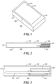
- FIG. 1 presents a view of an apparatus 100 having a housing 101 that presents a front surface 102 and a back surface 103.
- the apparatus 100 has a display 104 that comprises a part of that front surface 102.
- the apparatus 100 also includes a tray 105 that is configured to slide out of and into the housing 101.
- this tray 105 serves, in part, to at least partially contain a keyboard 200 and a corresponding bottom surface 201.
- FIG. 2 depicts both of these components in a fully non-deployed configuration. In this configuration both of these components are nested within the apparatus 100 and, as part of this configuration, are withdrawn longitudinally within the confines of the apparatus 100. So configured, neither the keyboard 200 nor the bottom surface 201 are visually observable from outside the apparatus 100.
- FIG. 3 provides an enlarged view of the keyboard 200 and the bottom surface 201 in the non-deployed configuration.
- the tray 105 includes an internal surface 301.
- this internal surface 301 comprises a rectangularly-shaped plate.
- the keyboard 200 contacts a first side of this internal surface 301 while the bottom surface 201 contacts an opposing second side of the internal surface 301.
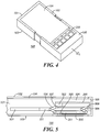
- FIG. 4 depicts the apparatus 100 with the tray 105 sliding forward towards a fully-opened position.
- the keyboard 200 becomes partially visible to a properly-positioned external observer.
- the keyboard 200 initially remains in contact with the aforementioned internal surface 301 as the tray 105 moves and hence the keyboard 200 moves substantially parallel to the housing 101 during this movement.
- the bottom surface 201 remains in contact with the internal surface 301 as the tray 105 slides forward toward the fully-opened position.
- FIG. 5 provides further elaboration in these regards.
- both the keyboard 200 and the bottom surface 201 are traveling in lockstep and in contact with the tray's internal surface 301.
- the internal surface 301 moves by sliding along a guide slot 501 formed on the internal sides of the housing 101.
- this sliding engagement can rely upon wheels (not shown) that fit within the aforementioned slots 501 and that freely rotate about axles (not shown) attached to the sides of the internal surface 301.
- the side edges of the internal surface 301 extend into and slide along the aforementioned slots 501.
- FIG. 5 also illustrates that the housing 101 can include tracks 502 and 503 that are also formed in the internal side walls thereof.
- both opposing side walls of the housing 101 include such tracks 502 and 503 and the tracks 502 and 503 are substantially straight and disposed substantially perpendicular to the longitudinal axis of the apparatus 100.
- these tracks 502 and 503 are formed by small flanges that extend outwardly of the housing's side walls.
- these tracks 502 and 503 comprise corresponding slots formed in the housing's side walls.
- FIG. 5 further illustrates that openings 504 and 505 are formed on both the front surface 102 and back surface 103 of the apparatus 100 as the tray 105 moves to a fully-opened position. These openings 504 and 505 occur because the keyboard 200 and the bottom surface 201 remain in a perpendicularly-withdrawn state as shown (in contact, at least for the most part, with the internal surface 301) as the tray 105 moves forward.
- both the keyboard 200 and the bottom surface 201 move substantially perpendicular to the housing 101.
- both the keyboard 200 and the bottom surface 201 move substantially perpendicular to the longitudinal axis of the housing 101 and in opposition to one another to both become substantially planar and flush with the front surface 102 and back surface 103, respectively.
- this perpendicular movement of the keyboard 200 is owing, in this illustrative example, to linkage arms 506 that pivotally couple to the interior surface 301 at one end of a first arm 506 and to a rotating wheel 507 and 508 at an opposing end thereof.
- These wheels 507 and 508, in turn, connect to the keyboard 200 via corresponding axles.
- the rearward wheels 507 in turn, track and follow corresponding ones of the aforementioned tracks 502.
- the corresponding linkage arms 506 follow accordingly to thereby move the keyboard 200 from the perpendicularly-withdrawn state shown in FIG. 5 to a fully-deployed state as shown in FIG. 7 such that the keyboard 200 becomes substantially planar with respect to the front surface 102 of the housing 101.
- the forward wheels 508 do not follow a corresponding track. Instead, the linkage arm 506 coupled to the forward wheel 508 simply follows the perpendicular movement of the keyboard 200 as described above to provide some additional support for the keyboard 200 in the deployed configuration. If desired, however, a similar track as described above could be provided to specifically guide this forward wheel 508 as well.
- a similar construct serves to move the bottom surface 201 perpendicular to the longitudinal axis of the housing 101 and opposite to the movement of the keyboard 200 as described above. So configured, as the tray 105 assumes a fully-withdrawn position the aforementioned openings 504 and 505 are effectively closed and filled by the keyboard 200 and bottom surface 201, respectively. This yields an apparatus 100 having a smooth and solid feel that is both aesthetically pleasing and physically supportive of robust use of the keyboard 200.
- the tray 105 By moving the tray 105 in a reverse direction to that described above, the foregoing components similarly reverse their movements. Accordingly, as the tray 105 closes, the keyboard 200 and bottom surface 201 withdraw perpendicularly into the tray 105 and into contact with the interior surface 301 and then move parallel to the housing 101 as the tray 105 continues sliding to a closed position.
- the keyboard 200 can include as many, or as few, keys (a few of which are denoted by reference numeral 601) as may be desired to meet the needs of a given application setting.
- the keyboard 200 can comprise a full QWERTY keyboard if desired.
- the apparatus 100 has a relatively small footprint when the keyboard 200 is stored in a non-deployed configuration.
- the keyboard 200 moves as described to a deployed configuration.
- the bottom surface 201 moves in synchronization with the movement of the keyboard 200 to also reach a deployed configuration.
- the openings 504 and 505 that are created by moving the tray 105 outwardly of the housing 101 become at least substantially filled by the keyboard 200 and bottom surface 201.
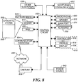
- an exemplary portable electronic device includes a control circuit 802 that controls the overall operation of the portable electronic device. Communication functions, including data and voice communications, are performed through a communication subsystem 804. The communication subsystem receives messages from and sends messages to a wireless network 850.
- the wireless network 850 may be any type of wireless network, including, but not limited to, data wireless networks, voice wireless networks, and networks that support both voice and data communications.
- a power source 842 such as one or more rechargeable batteries or a port to an external power supply, powers the electronic device.
- the control circuit 802 interacts with other elements, such as a Random Access Memory (RAM) 808, a memory 810, the aforementioned display 104 along with a touch-sensitive overlay 814 operably coupled to an electronic controller 816 that together comprise an optional touch-sensitive display 818, the aforementioned keypad 200, a data port 826, a speaker 828, a microphone 830, a short-range communication subsystem 832, and other device subsystems 834 of choice.
- RAM Random Access Memory
- memory 810 the aforementioned display 104
- a touch-sensitive overlay 814 operably coupled to an electronic controller 816 that together comprise an optional touch-sensitive display 818, the aforementioned keypad 200, a data port 826, a speaker 828, a microphone 830, a short-range communication subsystem 832, and other device subsystems 834 of choice.
- control circuit 802 also interacts with an accelerometer 836 that may be utilized to detect direction of gravitational forces or gravity-induced reaction forces.
- the portable electronic device may utilize a Subscriber Identity Module or a Removable User Identity Module (SIM/RUIM) card 838 for communication with a network, such as the wireless network 850.
- SIM/RUIM Removable User Identity Module
- user identification information may be programmed into the memory 810.
- the portable electronic device includes an operating system 846 and software programs, applications, or components 848 that are executed by the control circuit 802 and are typically stored in a persistent, updatable store such as the memory 810. Additional applications or programs may be loaded onto the portable electronic device through the wireless network 850, the data port 826, the short-range communications subsystem 832, or any other suitable subsystem 834.
- the memory 810 may comprise a non-transitory storage media that stores executable code, when executed, causes one or more functions or actions of choice to be undertaken.
- control circuit 802 can be configured to automatically respond to the deployed and non-deployed state of the keyboard 200 and/or the bottom surface 201 in any of a variety of ways. As one simple example in these regards, when the keyboard 200 is fully deployed the control circuit 802 can present, via the display 104, a user interface that presumes data entry via the keyboard 200. When, however, the keyboard 200 is stowed in the non-deployed configuration as described above, the control circuit 802 can be configured to present instead a user interface that presumes data entry via the touch-based overlay 814.
- one or more blocking or locking mechanisms can be provided to hold one or both of the aforementioned keyboard 200 and/or bottom surface 201 in the deployed and/or the non-deployed configurations.
Landscapes
- Engineering & Computer Science (AREA)
- Physics & Mathematics (AREA)
- Theoretical Computer Science (AREA)
- Signal Processing (AREA)
- Mathematical Physics (AREA)
- Computer Hardware Design (AREA)
- Human Computer Interaction (AREA)
- General Engineering & Computer Science (AREA)
- General Physics & Mathematics (AREA)
- Input From Keyboards Or The Like (AREA)
- Telephone Set Structure (AREA)
Description
- Data and instruction-entry keyboards of various kinds are known in the art. Keyboards are typically comprised of a plurality of keycaps (such as depressible buttons, touch-sensitive surfaces, and so forth) that permit a user to selectively enter any of a variety of alphanumeric characters and/or to input corresponding instructions or selections. Two common examples in these regards are the so-called QWERTY keyboard and the so-called telephone keypad.
- Small portable communication devices (such as so-called smartphones) often include a keyboard. To minimize the device's footprint those keyboards are sometimes disposed on a lower plane than the device's display. In these cases the display and the keyboard sometimes slide parallel to one another to bring the keyboard into a deployed position. In some other cases the keyboard comprises two or more multi-row segments that pivot in a planar fashion with respect to one another to permit the keyboard segments to be stored, again parallel to the device's display, as a stack of planar members within the device.
- US patent application no.
US2007243897 (A1 ) describes an extendible mobile electronic device with a housing having a first housing element comprising a first front surface and a first rear surface and a second housing element, comprising a second front surface and a second rear surface. Said first housing element, and said second housing element are extensibly supported to each other, such that said first and second housing elements can adopt a retracted position and an extended position with respect to each other. In said retracted position said first housing element and said second housing element are located substantially on top of each other, said first rear surface conformingly adjoining said second front surface. In said extended position said first housing element is displaced with respect to said second housing element and at least a section of said second front surface is adjoining said and flushing with said first front surface. - US patent application no.
US2006128449 (A1 ) discloses a sliding module for a sliding-type portable terminal having a pair of sliding rail modules adapted to slide the sliding housing of the terminal along a curved path. The sliding module includes a main housing extending along a longitudinal direction, a sliding housing adapted to slide along a curve in the longitudinal direction toward or away from the main housing, and a pair of sliding rail modules positioned on both sides of the housings to couple the sliding housing to the main housing in such a manner that the sliding housing can slide from the main housing along a curve in the longitudinal direction and to expose and hide predetermined regions of the upper surfaces of the housings. - International patent application no.
WO2008074358 (A1 ) describes a portable electronic apparatus comprising a first part with a first user interface, the first user interface extending along a first plane, and a second part with a second user interface, the second user interface extending along a second plane, the first and second parts arranged to be movable with respect to one another along an axis to provide second user interface retracted and in-use configurations, wherein the apparatus is arranged such that relative movement of the first and second parts along the axis provides the second user interface in the retracted configuration in which the second user interface is stowed away from use, the second user interface plane being in a different plane away from the first plane, and relative movement of the first and second parts along the axis provides the second user interface in the in-use configuration in which the second user interface has been moved from the stowed away position into an in-use position in which the second user interface plane has been moved relatively towards the first plane. -
US patent application no. 2011/0299235 describes a mobile computing device formed from at least two housing segments that can be moved between positions, including an open position that fully exposes a display surface or façade of each of the housing segments, and a closed position in which at least one of the facades or display surfaces is occluded or overlaid by the other housing segment. -
-
FIG. 1 is a perspective schematic view in accordance with the disclosure. -
FIG. 2 is a side-elevational schematic view in accordance with the disclosure. -
FIG. 3 is a side-elevational schematic view in accordance with the disclosure. -
FIG. 4 is a perspective schematic view in accordance with the disclosure. -
FIG. 5 is a side-elevational schematic view in accordance with the disclosure. -
FIG. 6 is a perspective schematic view in accordance with the disclosure. -
FIG. 7 is a side-elevational schematic view in accordance with the disclosure. -
FIG. 8 is a block diagram in accordance with the disclosure. - The following describes an apparatus pertaining to a housing having a front surface and a back surface, and further comprising a keyboard. The keyboard is configured to move between a non-deployed configuration and a deployed configuration. In the non-deployed configuration the keyboard is at least partially disposed within the housing. In the deployed configuration the keyboard is disposed substantially planar with the front surface of the housing.
- By one approach the apparatus further includes a bottom surface that also moves between a non-deployed configuration and a deployed configuration in synchronization with movement of the keyboard. This bottom surface is similarly disposed at least partially within the housing when in the non-deployed configuration and is substantially flush with the back surface of the housing when in the deployed configuration.
- By one approach the apparatus also comprises a tray that moves out of and into the housing by sliding along one or more guide slots that are formed internal to the housing. This tray can include an internal surface having a first side that contacts the keyboard when the latter is non-deployed and an opposing second side that contacts the aforementioned bottom surface when the latter is non-deployed.
- By one approach, when moving from the non-deployed configuration to the deployed configuration the keyboard first moves substantially parallel to the housing and then substantially perpendicular to the housing. By one approach, the keyboard can have one or more projections that interact with corresponding tracks formed in the housing to direct at the least this perpendicular movement of the keyboard. If desired, the bottom surface can be similarly configured to behave in a similar manner.
- So configured, a corresponding device such as a portable communication device can have both a small footprint when the keyboard is non-deployed while also offering a keyboard that can be readily and easily deployed when needed. The keyboard can be at least substantially flush with the front surface of the device to facilitate ease of use and offer an attractive aesthetic appearance. Similarly, the underside of the device can be smooth and without substantial interruption or surface discontinuity to thereby improve the use, stability, and feel of the device. These teachings are highly leverageable and are also easily scaled to accommodate a wide variety of device types and application settings.
- For simplicity and clarity of illustration, reference numerals may be repeated among the figures to indicate corresponding or analogous elements. Numerous details are set forth to provide an understanding of the embodiments described herein. The embodiments may be practiced without these details. In other instances, well-known methods, procedures, and components have not been described in detail to avoid obscuring the embodiments described.
-
FIG. 1 presents a view of anapparatus 100 having ahousing 101 that presents afront surface 102 and aback surface 103. In this illustrative example theapparatus 100 has adisplay 104 that comprises a part of thatfront surface 102. In this example theapparatus 100 also includes atray 105 that is configured to slide out of and into thehousing 101. - Referring to
FIG. 2 , thistray 105 serves, in part, to at least partially contain akeyboard 200 and acorresponding bottom surface 201.FIG. 2 depicts both of these components in a fully non-deployed configuration. In this configuration both of these components are nested within theapparatus 100 and, as part of this configuration, are withdrawn longitudinally within the confines of theapparatus 100. So configured, neither thekeyboard 200 nor thebottom surface 201 are visually observable from outside theapparatus 100. -
FIG. 3 provides an enlarged view of thekeyboard 200 and thebottom surface 201 in the non-deployed configuration. In this illustrative example thetray 105 includes aninternal surface 301. These teachings will accommodate a variety of approaches in these regards. By one approach, for example, thisinternal surface 301 comprises a rectangularly-shaped plate. In this example, when in the fully non-deployed position shown thekeyboard 200 contacts a first side of thisinternal surface 301 while thebottom surface 201 contacts an opposing second side of theinternal surface 301. - As noted above, the
tray 105 slides with respect to thehousing 101.FIG. 4 depicts theapparatus 100 with thetray 105 sliding forward towards a fully-opened position. As thetray 105 slides forward thekeyboard 200 becomes partially visible to a properly-positioned external observer. In this example thekeyboard 200 initially remains in contact with the aforementionedinternal surface 301 as thetray 105 moves and hence thekeyboard 200 moves substantially parallel to thehousing 101 during this movement. Also in this example, thebottom surface 201 remains in contact with theinternal surface 301 as thetray 105 slides forward toward the fully-opened position. -
FIG. 5 provides further elaboration in these regards. Here it can be perhaps more clearly seen that both thekeyboard 200 and thebottom surface 201 are traveling in lockstep and in contact with the tray'sinternal surface 301. By one approach, theinternal surface 301 moves by sliding along aguide slot 501 formed on the internal sides of thehousing 101. By one approach, if desired, this sliding engagement can rely upon wheels (not shown) that fit within theaforementioned slots 501 and that freely rotate about axles (not shown) attached to the sides of theinternal surface 301. By another approach, and as shown in this illustrative example, the side edges of theinternal surface 301 extend into and slide along theaforementioned slots 501. -
FIG. 5 also illustrates that thehousing 101 can includetracks housing 101 includesuch tracks tracks apparatus 100. By one approach thesetracks tracks -
FIG. 5 further illustrates thatopenings front surface 102 andback surface 103 of theapparatus 100 as thetray 105 moves to a fully-opened position. Theseopenings keyboard 200 and thebottom surface 201 remain in a perpendicularly-withdrawn state as shown (in contact, at least for the most part, with the internal surface 301) as thetray 105 moves forward. - Eventually, however, as the
tray 105 nears a fully-withdrawn state both thekeyboard 200 and thebottom surface 201 move substantially perpendicular to thehousing 101. As this occurs, and as illustrated inFIGS. 6 and 7 , both thekeyboard 200 and thebottom surface 201 move substantially perpendicular to the longitudinal axis of thehousing 101 and in opposition to one another to both become substantially planar and flush with thefront surface 102 andback surface 103, respectively. - With reference to both
FIGS. 5 and7 , this perpendicular movement of thekeyboard 200 is owing, in this illustrative example, tolinkage arms 506 that pivotally couple to theinterior surface 301 at one end of afirst arm 506 and to arotating wheel wheels keyboard 200 via corresponding axles. Therearward wheels 507, in turn, track and follow corresponding ones of the aforementioned tracks 502. - As the
rearward wheels 507 follow theirindividual tracks 502, the correspondinglinkage arms 506 follow accordingly to thereby move thekeyboard 200 from the perpendicularly-withdrawn state shown inFIG. 5 to a fully-deployed state as shown inFIG. 7 such that thekeyboard 200 becomes substantially planar with respect to thefront surface 102 of thehousing 101. - In this illustrative embodiment the
forward wheels 508 do not follow a corresponding track. Instead, thelinkage arm 506 coupled to theforward wheel 508 simply follows the perpendicular movement of thekeyboard 200 as described above to provide some additional support for thekeyboard 200 in the deployed configuration. If desired, however, a similar track as described above could be provided to specifically guide thisforward wheel 508 as well. - In this illustrative example a similar construct serves to move the
bottom surface 201 perpendicular to the longitudinal axis of thehousing 101 and opposite to the movement of thekeyboard 200 as described above. So configured, as thetray 105 assumes a fully-withdrawn position theaforementioned openings keyboard 200 andbottom surface 201, respectively. This yields anapparatus 100 having a smooth and solid feel that is both aesthetically pleasing and physically supportive of robust use of thekeyboard 200. - By moving the
tray 105 in a reverse direction to that described above, the foregoing components similarly reverse their movements. Accordingly, as thetray 105 closes, thekeyboard 200 andbottom surface 201 withdraw perpendicularly into thetray 105 and into contact with theinterior surface 301 and then move parallel to thehousing 101 as thetray 105 continues sliding to a closed position. - These teachings are suitable for use with a wide variety of keyboards. As shown in
FIG. 6 , thekeyboard 200 can include as many, or as few, keys (a few of which are denoted by reference numeral 601) as may be desired to meet the needs of a given application setting. As a more specific example in these regards, but without intending any limitations in these regards, thekeyboard 200 can comprise a full QWERTY keyboard if desired. - So configured, the
apparatus 100 has a relatively small footprint when thekeyboard 200 is stored in a non-deployed configuration. As thetray 105 moves outwardly, however, thekeyboard 200 moves as described to a deployed configuration. Similarly, thebottom surface 201 moves in synchronization with the movement of thekeyboard 200 to also reach a deployed configuration. In both cases, theopenings tray 105 outwardly of thehousing 101 become at least substantially filled by thekeyboard 200 andbottom surface 201. - These teachings are suitable for use with a wide variety of apparatuses. This can include, for example, a portable electronic device of choice. Referring to
FIG. 8 , an exemplary portable electronic device includes acontrol circuit 802 that controls the overall operation of the portable electronic device. Communication functions, including data and voice communications, are performed through acommunication subsystem 804. The communication subsystem receives messages from and sends messages to awireless network 850. Thewireless network 850 may be any type of wireless network, including, but not limited to, data wireless networks, voice wireless networks, and networks that support both voice and data communications. Apower source 842, such as one or more rechargeable batteries or a port to an external power supply, powers the electronic device. - The
control circuit 802 interacts with other elements, such as a Random Access Memory (RAM) 808, amemory 810, theaforementioned display 104 along with a touch-sensitive overlay 814 operably coupled to an electronic controller 816 that together comprise an optional touch-sensitive display 818, theaforementioned keypad 200, adata port 826, aspeaker 828, amicrophone 830, a short-range communication subsystem 832, andother device subsystems 834 of choice. - In this example, the
control circuit 802 also interacts with anaccelerometer 836 that may be utilized to detect direction of gravitational forces or gravity-induced reaction forces. To identify a subscriber for network access, the portable electronic device may utilize a Subscriber Identity Module or a Removable User Identity Module (SIM/RUIM)card 838 for communication with a network, such as thewireless network 850. Alternatively, user identification information may be programmed into thememory 810. - The portable electronic device includes an
operating system 846 and software programs, applications, orcomponents 848 that are executed by thecontrol circuit 802 and are typically stored in a persistent, updatable store such as thememory 810. Additional applications or programs may be loaded onto the portable electronic device through thewireless network 850, thedata port 826, the short-range communications subsystem 832, or any othersuitable subsystem 834. Thememory 810 may comprise a non-transitory storage media that stores executable code, when executed, causes one or more functions or actions of choice to be undertaken. - By one approach, the
control circuit 802 can be configured to automatically respond to the deployed and non-deployed state of thekeyboard 200 and/or thebottom surface 201 in any of a variety of ways. As one simple example in these regards, when thekeyboard 200 is fully deployed thecontrol circuit 802 can present, via thedisplay 104, a user interface that presumes data entry via thekeyboard 200. When, however, thekeyboard 200 is stowed in the non-deployed configuration as described above, thecontrol circuit 802 can be configured to present instead a user interface that presumes data entry via the touch-based overlay 814. - The present disclosure may be embodied in other specific forms without departing from its essential characteristics. For example, if desired, one or more blocking or locking mechanisms (such as a stop, detent, tongue-and-groove arrangement, tab, hook, or the like) can be provided to hold one or both of the
aforementioned keyboard 200 and/orbottom surface 201 in the deployed and/or the non-deployed configurations.
Claims (11)
- An apparatus (100) comprising:a housing (101) having a front surface (102) and a back surface (103);a keyboard (200) configured to move between a non-deployed configuration and a deployed configuration, wherein when in the non-deployed configuration the keyboard is disposed within the housing and when in the deployed configuration the keyboard is substantially planar with the front surface of the housing; anda bottom surface (201) configured to move between a non-deployed configuration and a deployed configuration in synchronization with movement of the keyboard, wherein when in the non-deployed configuration the bottom surface is disposed within the housing and when in the deployed configuration the bottom surface is substantially flush with the back surface of the housing; characterised in that the apparatus further comprises a tray (105) configured to slide with respect to the housing (101), wherein the tray is configured to slide along at least one slot (501) formed internal to the housing (101), and linkage arms (506) are pivotally coupled to the tray (105) and to a rotating wheel (507) on the keyboard (200) and on the bottom surface (201), whereby the linkage arms (507) move the keyboard (200) and the bottom surface (201) from the non-deployed configuration to the deployed configuration wherein the keyboard (200) is substantially planar with the front surface of the housing and the bottom surface (201) is substantially flush with the back surface of the housing.
- The apparatus of claim 1 wherein the apparatus comprises a portable communications device.
- The apparatus of claim 2 further comprising:
a display comprising a part of the front surface of the housing. - The apparatus of claim 1 wherein the keyboard comprises, at the least, a QWERTY keyboard.
- The apparatus of claim 1 wherein the keyboard is configured to, when moving from the non-deployed configuration to the deployed configuration, first move substantially parallel to the housing and then move substantially perpendicular to the housing.
- The apparatus of claim 5 wherein at least one projection on the keyboard interacts with at least one track formed in the housing to direct the perpendicular movement of the keyboard with respect to the housing.
- The apparatus of claim 1 wherein the bottom surface is configured to, when moving from the non-deployed configuration to the deployed configuration, first move substantially parallel to the housing and then move substantially perpendicular to the housing.
- The apparatus of claim 7 wherein at least one projection on the bottom surface interacts with at least one track formed in the housing to direct the perpendicular movement of the bottom surface with respect to the housing.
- The apparatus of claim 1 wherein the tray further comprises an internal surface having a first side that contacts the keyboard when the keyboard is in the non-deployed configuration and an opposing second side that contacts the bottom surface when the bottom surface is in the non-deployed configuration.
- The apparatus of claim 9 wherein the internal surface moves with the tray as the tray slides in and out of the housing.
- Apparatus as claimed in any preceding claim wherein the apparatus is a portable communications device and further comprising:
a display (104) supported by the housing facing outwardly away from the front surface of the housing
Priority Applications (1)
| Application Number | Priority Date | Filing Date | Title |
|---|---|---|---|
| EP12173381.0A EP2680098B1 (en) | 2012-06-25 | 2012-06-25 | Apparatus pertaining to a deployable keyboard and corresponding bottom surface |
Applications Claiming Priority (1)
| Application Number | Priority Date | Filing Date | Title |
|---|---|---|---|
| EP12173381.0A EP2680098B1 (en) | 2012-06-25 | 2012-06-25 | Apparatus pertaining to a deployable keyboard and corresponding bottom surface |
Publications (2)
| Publication Number | Publication Date |
|---|---|
| EP2680098A1 EP2680098A1 (en) | 2014-01-01 |
| EP2680098B1 true EP2680098B1 (en) | 2018-06-13 |
Family
ID=46516531
Family Applications (1)
| Application Number | Title | Priority Date | Filing Date |
|---|---|---|---|
| EP12173381.0A Active EP2680098B1 (en) | 2012-06-25 | 2012-06-25 | Apparatus pertaining to a deployable keyboard and corresponding bottom surface |
Country Status (1)
| Country | Link |
|---|---|
| EP (1) | EP2680098B1 (en) |
Citations (1)
| Publication number | Priority date | Publication date | Assignee | Title |
|---|---|---|---|---|
| US20110299235A1 (en) * | 2010-06-08 | 2011-12-08 | Eric Liu | Fully extendable dual-segmented housing assembly for mobile computing device |
Family Cites Families (3)
| Publication number | Priority date | Publication date | Assignee | Title |
|---|---|---|---|---|
| KR100617673B1 (en) * | 2004-12-06 | 2006-08-28 | 삼성전자주식회사 | Sliding module of sliding type mobile terminal and sliding type mobile terminal employing same |
| US7580726B2 (en) * | 2006-04-18 | 2009-08-25 | Nokia Corporation | Dual level slide mechanism for extendible device housings |
| WO2008074358A1 (en) * | 2006-12-21 | 2008-06-26 | Nokia Corporation | A portable electronic apparatus |
-
2012
- 2012-06-25 EP EP12173381.0A patent/EP2680098B1/en active Active
Patent Citations (1)
| Publication number | Priority date | Publication date | Assignee | Title |
|---|---|---|---|---|
| US20110299235A1 (en) * | 2010-06-08 | 2011-12-08 | Eric Liu | Fully extendable dual-segmented housing assembly for mobile computing device |
Also Published As
| Publication number | Publication date |
|---|---|
| EP2680098A1 (en) | 2014-01-01 |
Similar Documents
| Publication | Publication Date | Title |
|---|---|---|
| CN105518769B (en) | Flexible screen expansion structure, flexible screen assembly and terminal | |
| EP2728434B1 (en) | Support for a flexible display | |
| US20090061956A1 (en) | Housing for mobile computing device having construction to slide and pivot into multiple positions | |
| US8917499B1 (en) | Foldable keyboard | |
| EP2808753B1 (en) | Electronic device | |
| US11799993B2 (en) | Terminal device | |
| US8724317B2 (en) | Apparatus pertaining to a deployable keyboard and corresponding bottom surface | |
| EP2680098B1 (en) | Apparatus pertaining to a deployable keyboard and corresponding bottom surface | |
| KR100554801B1 (en) | Display panel rotating mobile phone | |
| EP2687940B1 (en) | Apparatus pertaining to a keyboard comprised of physically-discrete hinged segments | |
| US8891236B2 (en) | Housings that move using a link that slidingly engages cams | |
| CN103081447A (en) | Sliding device for electronic apparatus | |
| EP2688271B1 (en) | Apparatus pertaining to hinged rows of keycaps | |
| US20140022709A1 (en) | Apparatus Pertaining to Hinged Rows of Keycaps | |
| EP2674830B1 (en) | A storable keyboard having a pivoting cover | |
| US8804318B2 (en) | Storable keyboard having variable angular orientations | |
| KR101145889B1 (en) | Hinge apparatus for mobile phone | |
| EP2635005B1 (en) | A storable keyboard having variable angular orientations | |
| CA2730825C (en) | Portable electronic device with battery cover and locking mechanism therefor | |
| KR100866391B1 (en) | Slide module for mobile terminal | |
| KR20130080494A (en) | Personal portable device capable of tilting | |
| US8611973B2 (en) | Slidable portable electronic device with keypad portion adapted for covering display | |
| US20130335890A1 (en) | Storable Keyboard Having a Pivoting Cover | |
| JP5225397B2 (en) | Mobile communication terminal | |
| CN204288045U (en) | Electronic equipment |
Legal Events
| Date | Code | Title | Description |
|---|---|---|---|
| PUAI | Public reference made under article 153(3) epc to a published international application that has entered the european phase |
Free format text: ORIGINAL CODE: 0009012 |
|
| 17P | Request for examination filed |
Effective date: 20120625 |
|
| AK | Designated contracting states |
Kind code of ref document: A1 Designated state(s): AL AT BE BG CH CY CZ DE DK EE ES FI FR GB GR HR HU IE IS IT LI LT LU LV MC MK MT NL NO PL PT RO RS SE SI SK SM TR |
|
| AX | Request for extension of the european patent |
Extension state: BA ME |
|
| 17Q | First examination report despatched |
Effective date: 20140210 |
|
| 17Q | First examination report despatched |
Effective date: 20140217 |
|
| RIN1 | Information on inventor provided before grant (corrected) |
Inventor name: RIDDIFORD, MARTIN PHILIP Inventor name: GRIFFIN, JASON TYLER |
|
| GRAP | Despatch of communication of intention to grant a patent |
Free format text: ORIGINAL CODE: EPIDOSNIGR1 |
|
| INTG | Intention to grant announced |
Effective date: 20180103 |
|
| GRAS | Grant fee paid |
Free format text: ORIGINAL CODE: EPIDOSNIGR3 |
|
| GRAA | (expected) grant |
Free format text: ORIGINAL CODE: 0009210 |
|
| AK | Designated contracting states |
Kind code of ref document: B1 Designated state(s): AL AT BE BG CH CY CZ DE DK EE ES FI FR GB GR HR HU IE IS IT LI LT LU LV MC MK MT NL NO PL PT RO RS SE SI SK SM TR |
|
| REG | Reference to a national code |
Ref country code: GB Ref legal event code: FG4D |
|
| REG | Reference to a national code |
Ref country code: CH Ref legal event code: EP Ref country code: AT Ref legal event code: REF Ref document number: 1009114 Country of ref document: AT Kind code of ref document: T Effective date: 20180615 |
|
| REG | Reference to a national code |
Ref country code: FR Ref legal event code: PLFP Year of fee payment: 7 |
|
| REG | Reference to a national code |
Ref country code: IE Ref legal event code: FG4D |
|
| REG | Reference to a national code |
Ref country code: DE Ref legal event code: R096 Ref document number: 602012047361 Country of ref document: DE |
|
| REG | Reference to a national code |
Ref country code: NL Ref legal event code: MP Effective date: 20180613 |
|
| REG | Reference to a national code |
Ref country code: LT Ref legal event code: MG4D |
|
| PG25 | Lapsed in a contracting state [announced via postgrant information from national office to epo] |
Ref country code: CY Free format text: LAPSE BECAUSE OF FAILURE TO SUBMIT A TRANSLATION OF THE DESCRIPTION OR TO PAY THE FEE WITHIN THE PRESCRIBED TIME-LIMIT Effective date: 20180613 Ref country code: NO Free format text: LAPSE BECAUSE OF FAILURE TO SUBMIT A TRANSLATION OF THE DESCRIPTION OR TO PAY THE FEE WITHIN THE PRESCRIBED TIME-LIMIT Effective date: 20180913 Ref country code: SE Free format text: LAPSE BECAUSE OF FAILURE TO SUBMIT A TRANSLATION OF THE DESCRIPTION OR TO PAY THE FEE WITHIN THE PRESCRIBED TIME-LIMIT Effective date: 20180613 Ref country code: FI Free format text: LAPSE BECAUSE OF FAILURE TO SUBMIT A TRANSLATION OF THE DESCRIPTION OR TO PAY THE FEE WITHIN THE PRESCRIBED TIME-LIMIT Effective date: 20180613 Ref country code: BG Free format text: LAPSE BECAUSE OF FAILURE TO SUBMIT A TRANSLATION OF THE DESCRIPTION OR TO PAY THE FEE WITHIN THE PRESCRIBED TIME-LIMIT Effective date: 20180913 Ref country code: ES Free format text: LAPSE BECAUSE OF FAILURE TO SUBMIT A TRANSLATION OF THE DESCRIPTION OR TO PAY THE FEE WITHIN THE PRESCRIBED TIME-LIMIT Effective date: 20180613 Ref country code: LT Free format text: LAPSE BECAUSE OF FAILURE TO SUBMIT A TRANSLATION OF THE DESCRIPTION OR TO PAY THE FEE WITHIN THE PRESCRIBED TIME-LIMIT Effective date: 20180613 |
|
| PG25 | Lapsed in a contracting state [announced via postgrant information from national office to epo] |
Ref country code: LV Free format text: LAPSE BECAUSE OF FAILURE TO SUBMIT A TRANSLATION OF THE DESCRIPTION OR TO PAY THE FEE WITHIN THE PRESCRIBED TIME-LIMIT Effective date: 20180613 Ref country code: HR Free format text: LAPSE BECAUSE OF FAILURE TO SUBMIT A TRANSLATION OF THE DESCRIPTION OR TO PAY THE FEE WITHIN THE PRESCRIBED TIME-LIMIT Effective date: 20180613 Ref country code: GR Free format text: LAPSE BECAUSE OF FAILURE TO SUBMIT A TRANSLATION OF THE DESCRIPTION OR TO PAY THE FEE WITHIN THE PRESCRIBED TIME-LIMIT Effective date: 20180914 Ref country code: RS Free format text: LAPSE BECAUSE OF FAILURE TO SUBMIT A TRANSLATION OF THE DESCRIPTION OR TO PAY THE FEE WITHIN THE PRESCRIBED TIME-LIMIT Effective date: 20180613 |
|
| REG | Reference to a national code |
Ref country code: AT Ref legal event code: MK05 Ref document number: 1009114 Country of ref document: AT Kind code of ref document: T Effective date: 20180613 |
|
| PG25 | Lapsed in a contracting state [announced via postgrant information from national office to epo] |
Ref country code: NL Free format text: LAPSE BECAUSE OF FAILURE TO SUBMIT A TRANSLATION OF THE DESCRIPTION OR TO PAY THE FEE WITHIN THE PRESCRIBED TIME-LIMIT Effective date: 20180613 |
|
| PG25 | Lapsed in a contracting state [announced via postgrant information from national office to epo] |
Ref country code: AT Free format text: LAPSE BECAUSE OF FAILURE TO SUBMIT A TRANSLATION OF THE DESCRIPTION OR TO PAY THE FEE WITHIN THE PRESCRIBED TIME-LIMIT Effective date: 20180613 Ref country code: IS Free format text: LAPSE BECAUSE OF FAILURE TO SUBMIT A TRANSLATION OF THE DESCRIPTION OR TO PAY THE FEE WITHIN THE PRESCRIBED TIME-LIMIT Effective date: 20181013 Ref country code: EE Free format text: LAPSE BECAUSE OF FAILURE TO SUBMIT A TRANSLATION OF THE DESCRIPTION OR TO PAY THE FEE WITHIN THE PRESCRIBED TIME-LIMIT Effective date: 20180613 Ref country code: PL Free format text: LAPSE BECAUSE OF FAILURE TO SUBMIT A TRANSLATION OF THE DESCRIPTION OR TO PAY THE FEE WITHIN THE PRESCRIBED TIME-LIMIT Effective date: 20180613 Ref country code: CZ Free format text: LAPSE BECAUSE OF FAILURE TO SUBMIT A TRANSLATION OF THE DESCRIPTION OR TO PAY THE FEE WITHIN THE PRESCRIBED TIME-LIMIT Effective date: 20180613 Ref country code: RO Free format text: LAPSE BECAUSE OF FAILURE TO SUBMIT A TRANSLATION OF THE DESCRIPTION OR TO PAY THE FEE WITHIN THE PRESCRIBED TIME-LIMIT Effective date: 20180613 Ref country code: SK Free format text: LAPSE BECAUSE OF FAILURE TO SUBMIT A TRANSLATION OF THE DESCRIPTION OR TO PAY THE FEE WITHIN THE PRESCRIBED TIME-LIMIT Effective date: 20180613 |
|
| REG | Reference to a national code |
Ref country code: CH Ref legal event code: PL |
|
| PG25 | Lapsed in a contracting state [announced via postgrant information from national office to epo] |
Ref country code: SM Free format text: LAPSE BECAUSE OF FAILURE TO SUBMIT A TRANSLATION OF THE DESCRIPTION OR TO PAY THE FEE WITHIN THE PRESCRIBED TIME-LIMIT Effective date: 20180613 Ref country code: IT Free format text: LAPSE BECAUSE OF FAILURE TO SUBMIT A TRANSLATION OF THE DESCRIPTION OR TO PAY THE FEE WITHIN THE PRESCRIBED TIME-LIMIT Effective date: 20180613 |
|
| REG | Reference to a national code |
Ref country code: BE Ref legal event code: MM Effective date: 20180630 |
|
| REG | Reference to a national code |
Ref country code: DE Ref legal event code: R097 Ref document number: 602012047361 Country of ref document: DE |
|
| REG | Reference to a national code |
Ref country code: IE Ref legal event code: MM4A |
|
| PG25 | Lapsed in a contracting state [announced via postgrant information from national office to epo] |
Ref country code: LU Free format text: LAPSE BECAUSE OF NON-PAYMENT OF DUE FEES Effective date: 20180625 Ref country code: MC Free format text: LAPSE BECAUSE OF FAILURE TO SUBMIT A TRANSLATION OF THE DESCRIPTION OR TO PAY THE FEE WITHIN THE PRESCRIBED TIME-LIMIT Effective date: 20180613 |
|
| PLBE | No opposition filed within time limit |
Free format text: ORIGINAL CODE: 0009261 |
|
| STAA | Information on the status of an ep patent application or granted ep patent |
Free format text: STATUS: NO OPPOSITION FILED WITHIN TIME LIMIT |
|
| PG25 | Lapsed in a contracting state [announced via postgrant information from national office to epo] |
Ref country code: LI Free format text: LAPSE BECAUSE OF NON-PAYMENT OF DUE FEES Effective date: 20180630 Ref country code: CH Free format text: LAPSE BECAUSE OF NON-PAYMENT OF DUE FEES Effective date: 20180630 Ref country code: IE Free format text: LAPSE BECAUSE OF NON-PAYMENT OF DUE FEES Effective date: 20180625 |
|
| 26N | No opposition filed |
Effective date: 20190314 |
|
| PG25 | Lapsed in a contracting state [announced via postgrant information from national office to epo] |
Ref country code: SI Free format text: LAPSE BECAUSE OF FAILURE TO SUBMIT A TRANSLATION OF THE DESCRIPTION OR TO PAY THE FEE WITHIN THE PRESCRIBED TIME-LIMIT Effective date: 20180613 Ref country code: BE Free format text: LAPSE BECAUSE OF NON-PAYMENT OF DUE FEES Effective date: 20180630 Ref country code: DK Free format text: LAPSE BECAUSE OF FAILURE TO SUBMIT A TRANSLATION OF THE DESCRIPTION OR TO PAY THE FEE WITHIN THE PRESCRIBED TIME-LIMIT Effective date: 20180613 |
|
| PG25 | Lapsed in a contracting state [announced via postgrant information from national office to epo] |
Ref country code: AL Free format text: LAPSE BECAUSE OF FAILURE TO SUBMIT A TRANSLATION OF THE DESCRIPTION OR TO PAY THE FEE WITHIN THE PRESCRIBED TIME-LIMIT Effective date: 20180613 |
|
| PG25 | Lapsed in a contracting state [announced via postgrant information from national office to epo] |
Ref country code: MT Free format text: LAPSE BECAUSE OF NON-PAYMENT OF DUE FEES Effective date: 20180625 |
|
| PG25 | Lapsed in a contracting state [announced via postgrant information from national office to epo] |
Ref country code: TR Free format text: LAPSE BECAUSE OF FAILURE TO SUBMIT A TRANSLATION OF THE DESCRIPTION OR TO PAY THE FEE WITHIN THE PRESCRIBED TIME-LIMIT Effective date: 20180613 |
|
| PG25 | Lapsed in a contracting state [announced via postgrant information from national office to epo] |
Ref country code: PT Free format text: LAPSE BECAUSE OF FAILURE TO SUBMIT A TRANSLATION OF THE DESCRIPTION OR TO PAY THE FEE WITHIN THE PRESCRIBED TIME-LIMIT Effective date: 20180613 Ref country code: HU Free format text: LAPSE BECAUSE OF FAILURE TO SUBMIT A TRANSLATION OF THE DESCRIPTION OR TO PAY THE FEE WITHIN THE PRESCRIBED TIME-LIMIT; INVALID AB INITIO Effective date: 20120625 |
|
| PG25 | Lapsed in a contracting state [announced via postgrant information from national office to epo] |
Ref country code: MK Free format text: LAPSE BECAUSE OF NON-PAYMENT OF DUE FEES Effective date: 20180613 |
|
| REG | Reference to a national code |
Ref country code: DE Ref legal event code: R082 Ref document number: 602012047361 Country of ref document: DE Ref country code: DE Ref legal event code: R081 Ref document number: 602012047361 Country of ref document: DE Owner name: MALIKIE INNOVATIONS LTD., IE Free format text: FORMER OWNER: BLACKBERRY LIMITED, WATERLOO, ONTARIO, CA |
|
| REG | Reference to a national code |
Ref country code: GB Ref legal event code: 732E Free format text: REGISTERED BETWEEN 20240620 AND 20240627 |
|
| PGFP | Annual fee paid to national office [announced via postgrant information from national office to epo] |
Ref country code: DE Payment date: 20250626 Year of fee payment: 14 |
|
| PGFP | Annual fee paid to national office [announced via postgrant information from national office to epo] |
Ref country code: GB Payment date: 20250618 Year of fee payment: 14 |
|
| PGFP | Annual fee paid to national office [announced via postgrant information from national office to epo] |
Ref country code: FR Payment date: 20250624 Year of fee payment: 14 |