EP2679868A1 - Belt-type continuously variable transmission and vehicle with same - Google Patents
Belt-type continuously variable transmission and vehicle with same Download PDFInfo
- Publication number
- EP2679868A1 EP2679868A1 EP11859060.3A EP11859060A EP2679868A1 EP 2679868 A1 EP2679868 A1 EP 2679868A1 EP 11859060 A EP11859060 A EP 11859060A EP 2679868 A1 EP2679868 A1 EP 2679868A1
- Authority
- EP
- European Patent Office
- Prior art keywords
- circuit
- oil chamber
- communicate
- port
- oil
- Prior art date
- Legal status (The legal status is an assumption and is not a legal conclusion. Google has not performed a legal analysis and makes no representation as to the accuracy of the status listed.)
- Withdrawn
Links
Images





Classifications
-
- F—MECHANICAL ENGINEERING; LIGHTING; HEATING; WEAPONS; BLASTING
- F01—MACHINES OR ENGINES IN GENERAL; ENGINE PLANTS IN GENERAL; STEAM ENGINES
- F01B—MACHINES OR ENGINES, IN GENERAL OR OF POSITIVE-DISPLACEMENT TYPE, e.g. STEAM ENGINES
- F01B29/00—Machines or engines with pertinent characteristics other than those provided for in preceding main groups
-
- F—MECHANICAL ENGINEERING; LIGHTING; HEATING; WEAPONS; BLASTING
- F16—ENGINEERING ELEMENTS AND UNITS; GENERAL MEASURES FOR PRODUCING AND MAINTAINING EFFECTIVE FUNCTIONING OF MACHINES OR INSTALLATIONS; THERMAL INSULATION IN GENERAL
- F16H—GEARING
- F16H61/00—Control functions within control units of change-speed- or reversing-gearings for conveying rotary motion ; Control of exclusively fluid gearing, friction gearing, gearings with endless flexible members or other particular types of gearing
- F16H61/12—Detecting malfunction or potential malfunction, e.g. fail safe ; Circumventing or fixing failures
-
- F—MECHANICAL ENGINEERING; LIGHTING; HEATING; WEAPONS; BLASTING
- F16—ENGINEERING ELEMENTS AND UNITS; GENERAL MEASURES FOR PRODUCING AND MAINTAINING EFFECTIVE FUNCTIONING OF MACHINES OR INSTALLATIONS; THERMAL INSULATION IN GENERAL
- F16H—GEARING
- F16H61/00—Control functions within control units of change-speed- or reversing-gearings for conveying rotary motion ; Control of exclusively fluid gearing, friction gearing, gearings with endless flexible members or other particular types of gearing
- F16H61/66—Control functions within control units of change-speed- or reversing-gearings for conveying rotary motion ; Control of exclusively fluid gearing, friction gearing, gearings with endless flexible members or other particular types of gearing specially adapted for continuously variable gearings
- F16H61/662—Control functions within control units of change-speed- or reversing-gearings for conveying rotary motion ; Control of exclusively fluid gearing, friction gearing, gearings with endless flexible members or other particular types of gearing specially adapted for continuously variable gearings with endless flexible members
- F16H61/66254—Control functions within control units of change-speed- or reversing-gearings for conveying rotary motion ; Control of exclusively fluid gearing, friction gearing, gearings with endless flexible members or other particular types of gearing specially adapted for continuously variable gearings with endless flexible members controlling of shifting being influenced by a signal derived from the engine and the main coupling
- F16H61/66259—Control functions within control units of change-speed- or reversing-gearings for conveying rotary motion ; Control of exclusively fluid gearing, friction gearing, gearings with endless flexible members or other particular types of gearing specially adapted for continuously variable gearings with endless flexible members controlling of shifting being influenced by a signal derived from the engine and the main coupling using electrical or electronical sensing or control means
-
- F—MECHANICAL ENGINEERING; LIGHTING; HEATING; WEAPONS; BLASTING
- F16—ENGINEERING ELEMENTS AND UNITS; GENERAL MEASURES FOR PRODUCING AND MAINTAINING EFFECTIVE FUNCTIONING OF MACHINES OR INSTALLATIONS; THERMAL INSULATION IN GENERAL
- F16H—GEARING
- F16H61/00—Control functions within control units of change-speed- or reversing-gearings for conveying rotary motion ; Control of exclusively fluid gearing, friction gearing, gearings with endless flexible members or other particular types of gearing
- F16H61/12—Detecting malfunction or potential malfunction, e.g. fail safe ; Circumventing or fixing failures
- F16H2061/1232—Bringing the control into a predefined state, e.g. giving priority to particular actuators or gear ratios
- F16H2061/1236—Bringing the control into a predefined state, e.g. giving priority to particular actuators or gear ratios using fail priority valves
-
- F—MECHANICAL ENGINEERING; LIGHTING; HEATING; WEAPONS; BLASTING
- F16—ENGINEERING ELEMENTS AND UNITS; GENERAL MEASURES FOR PRODUCING AND MAINTAINING EFFECTIVE FUNCTIONING OF MACHINES OR INSTALLATIONS; THERMAL INSULATION IN GENERAL
- F16H—GEARING
- F16H61/00—Control functions within control units of change-speed- or reversing-gearings for conveying rotary motion ; Control of exclusively fluid gearing, friction gearing, gearings with endless flexible members or other particular types of gearing
- F16H61/12—Detecting malfunction or potential malfunction, e.g. fail safe ; Circumventing or fixing failures
- F16H2061/1256—Detecting malfunction or potential malfunction, e.g. fail safe ; Circumventing or fixing failures characterised by the parts or units where malfunctioning was assumed or detected
- F16H2061/126—Detecting malfunction or potential malfunction, e.g. fail safe ; Circumventing or fixing failures characterised by the parts or units where malfunctioning was assumed or detected the failing part is the controller
Definitions
- the present invention relates to belt type continuously variable transmissions and vehicles including the same. Note that the present application claims priority based on Japanese Patent Application No. 2011-38479 filed on February 24, 2011 , the entire contents of which are hereby incorporated by reference.
- a hydraulically-controlled belt type continuously variable transmission (hereinafter referred to as a "CVT") is conventionally known.
- a hydraulically-controlled CVT includes a driving pulley, a driven pulley, and a V-belt wound around both of the pulleys.
- Each pulley is provided with an oil chamber to which oil is supplied.
- the oil chamber is connected to a hydraulic circuit.
- the hydraulic circuit is provided with a control valve that controls a hydraulic pressure of the oil chamber.
- a controller controls the control valve, thus controlling the hydraulic pressure of the oil chamber. As a result, a transmission ratio of the CVT is controlled.
- the transmission ratio of the CVT cannot be controlled.
- a vehicle is required to be able to travel a certain distance, i.e., to "limp-home", so that the vehicle can reach a repair shop, for example, under its own power.
- a speed change cannot be performed while a reduction ratio remains small, it is difficult for the vehicle to start. Therefore, in order to ensure that the vehicle can "limp-home", various techniques are conventionally proposed to keep the reduction ratio of the CVT at a reduction ratio which enables the vehicle to start at the time of failure.
- Patent Literature 1 discloses that oil is trapped in an oil chamber of a driving pulley at the time of failure. The oil trapped in the oil chamber slowly leaks from a seal portion. Thus, a reduction ratio is gradually increased and is then kept in "LOW", i.e., at a maximum reduction ratio.
- Patent Literature 2 discloses that oil in an oil chamber is discharged at the time of failure, and that an orifice is provided in a circuit through which oil is discharged. The oil in the oil chamber is slowly discharged via the orifice, and therefore, a reduction ratio is gradually increased and is then kept in "LOW".
- Patent Literature 3 discloses a technique for allowing an oil chamber of a driving pulley to communicate with a high-pressure portion of a hydraulic circuit when a hydraulic pressure control valve is inoperative while an output port of the hydraulic pressure control valve remains in communication with a drain port. Thus, it is believed that a hydraulic pressure of the oil chamber is kept relatively high, and a reduction ratio is kept at a given value.
- Patent Literature 4 discloses a pressure regulating valve that keeps a hydraulic pressure of an oil chamber of a driving pulley at a given pressure at the time of failure. Thus, the hydraulic pressure of the oil chamber is kept at a constant pressure, and a reduction ratio is kept at a given value.
- Patent Literatures 1 and 2 With the techniques disclosed in Patent Literatures 1 and 2, a vehicle is allowed to start successfully by keeping the reduction ratio in "LOW" at the time of failure. However, even during traveling after the start, the reduction ratio is still in "LOW", which disadvantageously makes it impossible to ensure smooth traveling.
- the present invention has been made in view of the above-described problems, and its object is to provide a belt type continuously variable transmission capable of allowing a vehicle to start and travel smoothly and allowing the vehicle to "limp-home" more easily and reliably at the time of failure.
- a belt type continuously variable transmission is a belt type continuously variable transmission to be installed on a vehicle including an engine.
- the belt type continuously variable transmission includes a first pulley which includes a pair of first sheaves and a first oil chamber that contains oil and in which a distance between the pair of first sheaves is adjusted by a hydraulic pressure of the first oil chamber so that the distance between the pair of first sheaves is reduced as the hydraulic pressure of the first oil chamber increases, a second pulley including a pair of second sheaves, a belt wound between the pair of first sheaves and between the pair of second sheaves, and a hydraulic circuit connected to the first oil chamber.
- the hydraulic circuit includes a control valve that controls the hydraulic pressure of the first oil chamber, a pressure change circuit whose hydraulic pressure changes in accordance with a rotational speed of the engine so that the higher the rotational speed of the engine, the higher the hydraulic pressure in the pressure change circuit, and a switching valve that can be switched between a first state in which the control valve and the first oil chamber communicate with each other and a second state in which at least the first oil chamber and the pressure change circuit communicate with each other.
- the present invention can provide a belt type continuously variable transmission capable of allowing a vehicle to start and travel smoothly and allowing the vehicle to "limp-home" more easily and reliably at the time of failure.
- a belt type continuously variable transmission (CVT) 30 according to the present preferred embodiment is provided in a driving unit 7 of a motorcycle 1.
- the motorcycle 1 is provided as an example of a vehicle on which the belt type continuously variable transmission according to a preferred embodiment of the present invention is to be installed, and preferably is a scooter type motorcycle in the present preferred embodiment.
- a vehicle on which the belt type continuously variable transmission according to a preferred embodiment of the present invention is to be installed is not limited to a motorcycle.
- the motorcycle 1 includes a vehicle main body 9, a front wheel 2, and a rear wheel 3 serving as a driving wheel.
- the vehicle main body 9 is provided with a seat 5 on which a rider sits.
- the front wheel 2 is supported by a lower end portion of a front fork 4.
- a handlebar 6 is attached to an upper end portion of the front fork 4.
- the driving unit 7 provides a driving force to the rear wheel 3.
- the driving unit 7 includes an engine 20 and the CVT 30.
- the engine 20 includes a cylinder 21 in which a not-illustrated piston is slidably contained, a crankshaft connected to the piston via a not-illustrated connecting rod, and a crankcase 23 in which the crankshaft is contained.
- the CVT 30 is preferably disposed laterally of the crankcase 23.
- the motorcycle 1 includes a controller 10 that is arranged and programmed to control the engine 20 and the CVT 30, for example.
- An ECU Electronic Control Unit
- the controller 10 is preferably disposed above the driving unit 7. However, a position where the controller 10 is disposed is not limited to any particular position.
- the CVT 30 is preferably a hydraulically-controlled continuously variable transmission. As illustrated in FIG. 2 , the CVT 30 includes a hydraulic circuit 25.
- the CVT 30 includes a primary pulley 31 serving as a first pulley, a secondary pulley 32 serving as a second pulley, and a belt 33 wound around the primary pulley 31 and the secondary pulley 32.
- the primary pulley 31 includes a fixed sheave 31b and a movable sheave 31a movable in an axial direction (i.e., rightward and leftward in FIG. 2 ) with respect to the fixed sheave 31b.
- the movable sheave 31a and the fixed sheave 31b are connected to a primary shaft 36.
- the movable sheave 31a and the fixed sheave 31b rotate together with the primary shaft 36.
- the primary shaft 36 is directly or indirectly connected to the crankshaft (not illustrated) of the engine 20.
- the primary shaft 36 rotates by receiving a torque of the crankshaft. Note that a portion of the crankshaft may constitute the primary shaft 36.
- the secondary pulley 32 includes a fixed sheave 32b and a movable sheave 32a movable in the axial direction (i.e., rightward and leftward in FIG. 2 ) with respect to the fixed sheave 32b.
- the movable sheave 32a and the fixed sheave 32b are connected to a secondary shaft 34.
- the secondary shaft 34 rotates together with the movable sheave 32a and the fixed sheave 32b.
- the secondary shaft 34 is directly or indirectly connected to the rear wheel 3.
- the rear wheel 3 rotates by receiving a torque of the secondary shaft 34.
- the belt 33 is preferably a metal belt.
- the belt 33 is not limited to a metal belt, but may be selected from other types of belts such as a resin belt.
- the belt 33 is located between the movable sheave 31a and the fixed sheave 31b of the primary pulley 31, and between the movable sheave 32a and the fixed sheave 32b of the secondary pulley 32.
- a distance between the movable sheave 31a and the fixed sheave 31b and a distance between the movable sheave 32a and the fixed sheave 32b are each changed, thus changing a reduction ratio of the CVT 30.
- the reduction ratio is in "OVERDRIVE" (i.e., at a minimum reduction ratio), which will hereinafter be referred to as "OD".
- the reduction ratio is in "LOW” (i.e., at a maximum reduction ratio).
- the reduction ratio can be freely adjusted between "OD" and "LOW".
- the reduction ratio is controlled by utilizing a hydraulic pressure.
- the primary pulley 31 is provided with a first oil chamber 41. Oil is supplied from the hydraulic circuit 25 to the first oil chamber 41 as appropriate, and is discharged from the first oil chamber 41 to the hydraulic circuit 25 as appropriate.
- the movable sheave 31a is arranged so as to be axially moved in accordance with a hydraulic pressure of the first oil chamber 41. The movable sheave 31a comes close to the fixed sheave 31b upon an increase in hydraulic pressure of the first oil chamber 41, and the movable sheave 31a moves away from the fixed sheave 31b upon a reduction in hydraulic pressure of the first oil chamber 41.
- the reduction ratio decreases upon an increase in hydraulic pressure of the first oil chamber 41, and the reduction ratio increases upon a reduction in hydraulic pressure of the first oil chamber 41.
- the secondary pulley 32 is provided with a second oil chamber 42. Oil is supplied from the hydraulic circuit 25 to the second oil chamber 42 as appropriate, and is discharged from the second oil chamber 42 to the hydraulic circuit 25 as appropriate.
- the movable sheave 32a is arranged so as to be axially moved in accordance with a hydraulic pressure of the second oil chamber 42.
- the movable sheave 32a comes close to the fixed sheave 32b upon an increase in hydraulic pressure of the second oil chamber 42, and the movable sheave 32a moves away from the fixed sheave 32b upon a reduction in hydraulic pressure of the second oil chamber 42.
- the reduction ratio increases upon an increase in hydraulic pressure of the second oil chamber 42, and the reduction ratio decreases upon a reduction in hydraulic pressure of the second oil chamber 42.
- first oil chamber 41 may be provided integrally with the movable sheave 31a, or may be provided separately from the movable sheave 31a.
- first oil chamber 41 may be provided inside a hydraulic actuator provided separately from the movable sheave 31a.
- second oil chamber 42 may be provided integrally with the movable sheave 32a, or may be provided separately from the movable sheave 32a.
- the second oil chamber 42 may be provided inside a hydraulic actuator provided separately from the movable sheave 32a.
- the hydraulic circuit 25 includes a tank 50 in which oil is stored, an oil pump 51, a first control valve 53 serving as an example of a control valve that controls the hydraulic pressure of the first oil chamber 41, a second control valve 56 serving as an example of a pressure reducing mechanism that controls the hydraulic pressure of the second oil chamber 42, and a fail-safe valve 54 serving as an example of a switching valve.
- the oil pump 51 is indirectly connected to the crankshaft of the engine 20 so as to be operated in conjunction with the engine 20.
- the engine rotational speed refers to the rotational speed of the crankshaft.
- a flow rate of oil discharged from the oil pump 51 is increased as the engine rotational speed is increased, and the flow rate of oil discharged from the oil pump 51 is reduced as the engine rotational speed is reduced.
- a suction circuit 60 through which the tank 50 and a suction-side portion of the oil pump 51 are connected to each other is provided with a strainer 52.
- a discharge-side portion of the oil pump 51 and the second oil chamber 42 communicate with each other via a first circuit 61.
- the fail-safe valve 54 preferably includes an electromagnetic four-way valve, and includes a first port 54a, a second port 54b, a third port 54c and a fourth port 54d.
- the first circuit 61 and the first port 54a of the fail-safe valve 54 communicate with each other through a second circuit 62.
- the first control valve 53 is provided in the second circuit 62.
- the first control valve 53 is preferably an electromagnetic pressure control valve that adjusts a downstream pressure.
- the first control valve 53 receives a control signal from the controller 10 to control the hydraulic pressure of the first oil chamber 41 within a pressure range between given minimum and maximum pressures. When the first control valve 53 receives no control signal from the controller 10, i.e., when the first control valve 53 is not energized, a set pressure of the first control valve 53 is the maximum pressure.
- the third circuit 63 is provided with an orifice 55.
- the hydraulic circuit 25 includes a lubrication circuit 80 serving as an example of a pressure change circuit that is opened toward a sliding portion 70 of the engine 20 or the CVT 30.
- the lubrication circuit 80 is a circuit through which oil is supplied to the sliding portion 70.
- the sliding portion 70 is lubricated with oil supplied from the lubrication circuit 80.
- the lubrication circuit 80 is provided with an orifice 59.
- the second control valve 56 is provided in the fourth circuit 64.
- the second control valve 56 is preferably an electromagnetic pressure control valve that adjusts an upstream pressure.
- the second control valve 56 receives a control signal from the controller 10 to control the hydraulic pressure of the second oil chamber 42 within a pressure range between given minimum and maximum pressures.
- a set pressure of the second control valve 56 is the maximum pressure.
- the sixth circuit 66 is provided with an orifice 58.
- the seventh circuit 67 is provided with a relief valve 57.
- the relief valve 57 allows some of the oil in the lubrication circuit 80 to flow out to the suction circuit 60 so that the hydraulic pressure of the lubrication circuit 80 falls below the upper limit.
- the relief valve 57 is arranged so as to be opened when the upstream hydraulic pressure reaches the upper limit, which is set in advance.
- the fail-safe valve 54 When the fail-safe valve 54 receives a control signal from the controller 10, i.e., when the fail-safe valve 54 is energized, the fail-safe valve 54 enters a state (first state) in which the first port 54a and the third port 54c communicate with each other and the second port 54b and the fourth port 54d do not communicate with each other. Conversely, when the fail-safe valve 54 receives no control signal from the controller 10, i.e., when the fail-safe valve 54 is not energized, the fail-safe valve 54 enters a state (second state) in which the first port 54a and the second port 54b communicate with each other and the third port 54c and the fourth port 54d communicate with each other.
- the control signal is supplied from the controller 10 to the first control valve 53, the second control valve 56 and the fail-safe valve 54.
- the fail-safe valve 54 enters the state in which the first port 54a and the third port 54c communicate with each other and the second port 54b and the fourth port 54d do not communicate with each other.
- the first control valve 53 and the second control valve 56 control the hydraulic pressures of the first oil chamber 41 and the second oil chamber 42, respectively, thus controlling the reduction ratio of the CVT 30 to a given value.
- the controller 10 controls the reduction ratio of the CVT 30 in accordance with an operating state of the motorcycle 1.
- a portion of the oil discharged from the oil pump 51 passes through the first control valve 53 to become oil having a given pressure.
- This oil passes through the first port 54a and the third port 54c of the fail-safe valve 54, and is supplied to the first oil chamber 41. Therefore, the hydraulic pressure of the first oil chamber 41 is controlled to be a given pressure.
- the other portion of the oil discharged from the oil pump 51 is supplied to the second oil chamber 42 through the first circuit 61.
- the hydraulic pressure of the first circuit 61 is controlled to be a given pressure by the second control valve 56.
- the hydraulic pressure of the second oil chamber 42 is controlled to be a given pressure.
- Oil discharged from the second control valve 56 is supplied to the lubrication circuit 80, and is then supplied as lubricating oil to the sliding portion 70.
- the oil utilized as lubricating oil is collected into the tank 50.
- the relief valve 57 is opened, and a portion of the oil in the lubrication circuit 80 is sucked into the oil pump 51 through the seventh circuit 67.
- failure refers to a state in which the hydraulic pressure (s) of the first oil chamber 41 and/or the second oil chamber 42 cannot be controlled, and as a consequence the CVT 30 cannot be properly controlled.
- the "failure” corresponds to, for example, a failure of the controller 10, a failure of the first control valve 53, a failure of the second control valve 56, a break in a signal line through which the controller 10 and the first control valve 53 are connected to each other, and a break in a signal line through which the controller 10 and the second control valve 56 are connected to each other.
- the fail-safe valve 54 Upon stoppage of transmission of the control signal from the controller 10 to the fail-safe valve 54, the fail-safe valve 54 is switched to the state in which the first port 54a and the second port 54b communicate with each other and the third port 54c and the fourth port 54d communicate with each other as illustrated in FIG. 3 .
- the set pressure of the first control valve 53 i.e., the hydraulic pressure of the second circuit 62, for example
- the set pressure of the second control valve 56 i.e., the hydraulic pressure of the first circuit 61, for example
- the set pressures of the first control valve 53 and the second control valve 56 are controlled to the maximum pressures at the time of failure in this manner in order to support the belt 33 by the primary pulley 31 and the secondary pulley 32 as firmly as possible by increasing the hydraulic pressures of the first oil chamber 41 and the second oil chamber 42, so that the belt 33 does not slide with respect to the primary pulley 31 and the secondary pulley 32.
- Some of the oil discharged from the oil pump 51 is reduced in pressure through the first control valve 53, and then passes through the first port 54a and the second port 54b of the fail-safe valve 54 to flow into the third circuit 63.
- this oil flows into the first oil chamber 41.
- the reduction ratio of the CVT 30 at the time of failure is small (e.g., in the case of "OD")
- the hydraulic pressure of the first oil chamber 41 is low, and therefore, the oil passed through the first control valve 53 flows into the first oil chamber 41.
- the hydraulic pressure of the first oil chamber 41 increases. Note that a flow of the oil passed through the first port 54a and the second port 54b is reduced by the orifice 55, and therefore, an abrupt change in the pressure of the first oil chamber 41 is prevented. Consequently, an abrupt change in the reduction ratio is prevented.
- the sixth circuit 66 is provided with the orifice 58, thus preventing an excessive reduction in hydraulic pressure of a portion located upstream of the orifice 58, i.e., a component such as the first oil chamber 41.
- the hydraulic pressure of the first oil chamber 41 is maintained at a high level.
- the oil of the sixth circuit 66 is supplied to the lubrication circuit 80.
- the hydraulic pressure of the lubrication circuit 80 exceeds the upper limit due to the flow of the oil of the sixth circuit 66 into the lubrication circuit 80, some of this oil flows into the suction circuit 60 through the relief valve 57 and the seventh circuit 67. Accordingly, even when high-pressure oil flows into the lubrication circuit 80 through the sixth circuit 66, the hydraulic pressure of the lubrication circuit 80 will not be excessively increased. A smooth lubricating operation performed by the lubrication circuit 80 will not be hindered, and an excessive supply of oil to the sliding portion 70 will be prevented.
- FIG. 4(a) is a time chart showing hydraulic pressure changes at the time of failure.
- the horizontal axis represents time
- t1 denotes a time at which a failure has occurred.
- P1, P2 and P3 denote the hydraulic pressure of the first oil chamber 41, the hydraulic pressure of the second oil chamber 42, and the hydraulic pressure of the lubrication circuit 80, respectively.
- P1' denotes the hydraulic pressure of the first oil chamber 41 obtained in an example (hereinafter referred to as a "comparative example") where the fail-safe valve 54 and the sixth circuit 66 are omitted and the second circuit 62 and the third circuit 63 are connected in series.
- the set pressure of the first control valve 53 becomes the maximum pressure, and thus both of P1 and P1' increase.
- the hydraulic pressure of the first oil chamber 41 substantially corresponds to the maximum pressure of the first control valve 53, and therefore, P1' remains constant at the maximum pressure.
- the sixth circuit 66 is provided with the orifice 58, P1 is temporarily higher than P1' immediately after the occurrence of failure, but in the course of time, the oil of the first oil chamber 41 is discharged to the lubrication circuit 80 through the sixth circuit 66 resulting in a gradual reduction in P1.
- the set pressure of the second control valve 56 also becomes the maximum pressure at the time of failure, and therefore, P2 increases concurrently with the occurrence of failure and then remains constant.
- FIG. 4(b) is a time chart showing reduction ratios at the time of failure.
- R denotes a reduction ratio in the present preferred embodiment
- R' denotes a reduction ratio in the comparative example.
- R' abruptly changes but R moderately changes immediately after the occurrence of failure. It is also evident that upon lapse of a certain period of time after the occurrence of failure, R' does not change, but R continues to change and becomes higher than R' in the course of time.
- the reduction ratio R will be closer to "LOW” than the reduction ratio R'.
- "OD" in FIG. 4(b) means “OVERDRIVE" and represents a state in which the reduction ratio is small.
- FIG. 4(c) is a time chart showing vehicle speeds of the motorcycle 1 at the time of failure.
- V denotes a vehicle speed in the present preferred embodiment
- V' denotes a vehicle speed in the comparative example.
- V' abruptly changes but V moderately changes immediately after the occurrence of failure. After a lapse of a certain period of time since the occurrence of failure, V becomes lower than V'.
- FIG. 5(a) is a time chart showing hydraulic pressure changes obtained when the motorcycle 1 temporarily stops after the occurrence of failure and then makes a start (hereinafter referred to as "restart").
- the horizontal axis represents time
- t2 denotes a time at which a restart is made.
- P3 increases after the restart. This is because as the engine rotational speed increases, the rotational speed of the oil pump 51 increases, and the hydraulic pressure of the lubrication circuit 80 increases.
- the first oil chamber 41 communicates with the lubrication circuit 80 via the sixth circuit 66, for example, and therefore, P1 increases as P3 increases. In this manner, P1 increases as the engine rotational speed increases.
- FIG. 5 (b) is a time chart showing reduction ratios at the time of restart.
- R' does not change and remains constant, but R decreases. This is because as the engine rotational speed increases, the hydraulic pressure P1 of the first oil chamber 41 increases, and the movable sheave 31a of the primary pulley 31 comes close to the fixed sheave 31b thereof. In this manner, according to the present preferred embodiment, the vehicle restarts at the maximum reduction ratio and then the reduction ratio decreases during traveling.
- FIG. 5(c) is a time chart showing vehicle speeds at the time of restart.
- the degree of increase in V is greater than the degree of increase in V' (i.e., an acceleration of V is greater than that of V'), and therefore, favorable acceleration characteristics can be achieved in the present preferred embodiment.
- the vehicle can restart at a large reduction ratio, and in addition, the reduction ratio decreases after the restart, thus making it possible to achieve favorable acceleration characteristics.
- the state of the fail-safe valve 54 is switched at the time of failure, and the first oil chamber 41 communicates with the lubrication circuit 80, i.e., the circuit whose hydraulic pressure changes in accordance with the engine rotational speed. Therefore, the hydraulic pressure of the first oil chamber 41 changes in accordance with the engine rotational speed.
- the hydraulic pressure of the first oil chamber 41 changes in accordance with the engine rotational speed.
- the hydraulic pressure of the first oil chamber 41 is relatively low, and the reduction ratio is relatively large. Accordingly, a smooth start is enabled.
- the engine rotational speed is higher than that at the time of restart, and the hydraulic pressure of the first oil chamber 41 is relatively increased, resulting in a relatively small reduction ratio. Accordingly, smooth traveling is enabled.
- the reduction ratio changes to some extent in accordance with the traveling state of the motorcycle 1, thus making it possible to achieve both a smooth start and smooth traveling.
- the vehicle is able to "limp-home" more easily and reliably.
- the hydraulic circuit 25 includes the oil pump 51 operated in conjunction with the engine 20.
- the lubrication circuit 80 is a circuit that communicates with the discharge-side portion of the oil pump 51 via the second control valve 56 functioning as the pressure reducing mechanism.
- the oil pump 51 and the second control valve 56 constitute a circuit whose hydraulic pressure changes in accordance with the engine rotational speed. According to the present preferred embodiment, the pressure change circuit whose hydraulic pressure changes in accordance with the engine rotational speed can be easily provided.
- the lubrication circuit 80 is a circuit originally provided to supply oil to the sliding portion 70.
- the existing circuit can be used as the circuit whose hydraulic pressure changes in accordance with the engine rotational speed.
- the third circuit 63 is provided with the orifice 55, and thus the orifice 55 reduces the flow of oil from the first control valve 53 toward the first oil chamber 41 at the time of failure. Therefore, the hydraulic pressure of the first oil chamber 41 is prevented from being abruptly changed at the time of failure. Accordingly, an abrupt change in the reduction ratio at the time of failure can be prevented.
- the lubrication circuit 80 communicates with the suction circuit 60 via the seventh circuit 67, and the seventh circuit 67 is provided with the relief valve 57. Hence, even when the state of the fail-safe valve 54 is switched to cause a large amount of oil to flow into the lubrication circuit 80 at the time of failure, an excessive increase in hydraulic pressure of the lubrication circuit 80 is avoided. Accordingly, a smooth lubricating operation performed by the lubrication circuit 80 will not be hindered.
- the sixth circuit 66 is provided with the orifice 58, the hydraulic pressure of the first oil chamber 41 is maintained at a high level when the state of the fail-safe valve 54 is switched to cause the first oil chamber 41 and the lubrication circuit 80 to communicate with each other at the time of failure.
- a change in hydraulic pressure of the first oil chamber 41 can be moderated.
- the lubrication circuit 80 is utilized as the pressure change circuit whose hydraulic pressure changes in accordance with the engine rotational speed. As illustrated in FIG. 6 , in the second preferred embodiment, a portion of the hydraulic circuit 25 according to the first preferred embodiment is modified, so that the pressure change circuit is provided separately from the lubrication circuit 80.
- a portion of the first circuit 61 located adjacent to the discharge-side portion of the oil pump 51 is provided with an orifice 71.
- a portion of the first circuit 61 located between the oil pump 51 and the orifice 71, and a portion of the suction circuit 60 located between the oil pump 51 and the strainer 52 communicate with each other via an eighth circuit 68.
- the eighth circuit 68 is provided with an orifice 72 and an orifice 73.
- a hydraulic pressure of a portion of the eighth circuit 68 located between the orifice 72 and the orifice 73 increases as the engine rotational speed increases, and decreases as the engine rotational speed decreases.
- the portion of the eighth circuit 68 located between the orifice 72 and the orifice 73 is utilized as the pressure change circuit.
- the sixth circuit 66 connects the fourth port 54d of the fail-safe valve 54 and the lubrication circuit 80 to each other (see FIG. 2 ).
- one end of the sixth circuit 66 is connected to the fourth port 54d of the fail-safe valve 54, and the other end of the sixth circuit 66 is connected to the portion of the eighth circuit 68 located between the orifice 72 and the orifice 73.
- a portion of the hydraulic circuit 25 according to the first preferred embodiment is modified, so that the reduction ratio at the time of failure is more variable than that in the first preferred embodiment.
- a fail-safe valve 74 is provided instead of the fail-safe valve 54.
- FIG. 8 (a) is a diagram including reference signs indicating the fail-safe valve 74
- FIG. 8(b) is a conceptual diagram illustrating a configuration of the fail-safe valve 74.
- the fail-safe valve 74 is preferably an electromagnetic four-way valve, and includes a first port 74a, a second port 74b, a third port 74c and a fourth port 74d.
- the fail-safe valve 74 is controlled by the controller 10.
- the fail-safe valve 74 includes a solenoid 74e that generates a downward force upon reception of a control signal from the controller 10, and a spool 74p that is pushed downward by the solenoid 74e.
- the spool 74p is provided with a land 74f. Note that as used herein, "upward” and “downward” directions merely mean directions indicated in the drawings, and do not necessarily mean actual directions when the fail-safe valve 74 is installed.
- An oil chamber 76 is provided in the fail-safe valve 74, and the sixth circuit 66 and the oil chamber 76 communicate with each other via a communication passage 75.
- the fail-safe valve 74 enters, during normal operation, a state (first state) in which the first port 74a and the third port 74c communicate with each other and the second port 74b and the fourth port 74d do not communicate with each other.
- the fail-safe valve 74 At the time of failure, transmission of the control signal from the controller 10 to the fail-safe valve 74 is stopped, and the fail-safe valve 74 enters a non-energized state. As a result, the solenoid 74e does not operate, and the force for pushing the spool 74p downward is lost, so that the spool 74p is urged upward by a spring 74s. Since the oil chamber 76 communicates with the sixth circuit 66 via the communication passage 75, the hydraulic pressure of the oil chamber 76 is equal to that of the sixth circuit 66. The hydraulic pressure of the oil chamber 76 acts on the land 74f, and the spool 74p receives the downward force due to the hydraulic pressure. The sixth circuit 66 communicates with the lubrication circuit 80, and the hydraulic pressure of the sixth circuit 66 changes in accordance with the engine rotational speed. Hence, the hydraulic pressure of the oil chamber 76 also changes in accordance with the engine rotational speed.
- FIGS. 10(a) and 10(b) illustrate a state in which the entire fourth port 74d is closed.
- An opening area of the fourth port 74d depends on the position of the land 74f, so that the higher the position of the land 74f, the greater the opening area, and the lower the position of the land 74f, the smaller the opening area.
- the opening area of the fourth port 74d changes in accordance with the pressures of the sixth circuit 66 and the oil chamber 76.
- the hydraulic pressures of the sixth circuit 66 and the oil chamber 76 are reduced, and therefore, the opening area of the fourth port 74d is increased.
- the opening area of the fourth port 74d is increased, the amount of oil discharged from the first oil chamber 41 through the third port 74c and the fourth port 74d is increased. Hence, the hydraulic pressure of the first oil chamber 41 is reduced, and the reduction ratio of the CVT 30 is increased.
- the hydraulic pressures of the sixth circuit 66 and the oil chamber 76 are increased, and therefore, the opening area of the fourth port 74d is reduced.
- the opening area of the fourth port 74d is reduced, the amount of oil discharged from the first oil chamber 41 through the third port 74c and the fourth port 74d is reduced.
- the hydraulic pressure of the first oil chamber 41 is increased, and the reduction ratio of the CVT 30 is reduced.
- the opening area of the fourth port 74d changes not only in accordance with a change in the hydraulic pressure of the lubrication circuit 80, but also in accordance with this change in hydraulic pressure, the hydraulic pressure of the first oil chamber 41 can be more variable. Accordingly, the reduction ratio can be more variable. According to the present preferred embodiment, when the engine rotational speed is increased, the reduction ratio can be further reduced, thus allowing the reduction ratio to assume a more suitable value for high speed traveling. Accordingly, the vehicle is able to "limp-home" even more easily and reliably.
- preferred embodiments of the present invention can provide a belt type continuously variable transmission that enables the vehicle to "limp-home" easily and reliably.
Landscapes
- Engineering & Computer Science (AREA)
- General Engineering & Computer Science (AREA)
- Mechanical Engineering (AREA)
- Control Of Transmission Device (AREA)
Abstract
A hydraulic circuit 25 includes a first control valve 53 that controls a hydraulic pressure of a first oil chamber 41 of a CVT 30; a lubrication circuit 80 whose hydraulic pressure changes in accordance with an engine rotational speed so that the higher the engine rotational speed, the higher the hydraulic pressure; and a fail-safe valve 54 including an electromagnetic four-way valve. During normal operation, the fail-safe valve 54 is set to a first state in which the first control valve 53 and the first oil chamber 41 communicate with each other. At a time of failure, the fail-safe valve 54 is switched to a second state in which at least the first oil chamber 41 and the lubrication circuit 80 communicate with each other.
Description
- The present invention relates to belt type continuously variable transmissions and vehicles including the same.
Note that the present application claims priority based on Japanese Patent Application No.2011-38479 filed on February 24, 2011 - A hydraulically-controlled belt type continuously variable transmission (hereinafter referred to as a "CVT") is conventionally known. A hydraulically-controlled CVT includes a driving pulley, a driven pulley, and a V-belt wound around both of the pulleys. Each pulley is provided with an oil chamber to which oil is supplied. The oil chamber is connected to a hydraulic circuit. The hydraulic circuit is provided with a control valve that controls a hydraulic pressure of the oil chamber. A controller controls the control valve, thus controlling the hydraulic pressure of the oil chamber. As a result, a transmission ratio of the CVT is controlled.
- Upon occurrence of failure in the controller, for example, the transmission ratio of the CVT cannot be controlled. However, even at the time of failure, a vehicle is required to be able to travel a certain distance, i.e., to "limp-home", so that the vehicle can reach a repair shop, for example, under its own power. When a speed change cannot be performed while a reduction ratio remains small, it is difficult for the vehicle to start. Therefore, in order to ensure that the vehicle can "limp-home", various techniques are conventionally proposed to keep the reduction ratio of the CVT at a reduction ratio which enables the vehicle to start at the time of failure.
-
Patent Literature 1 discloses that oil is trapped in an oil chamber of a driving pulley at the time of failure. The oil trapped in the oil chamber slowly leaks from a seal portion. Thus, a reduction ratio is gradually increased and is then kept in "LOW", i.e., at a maximum reduction ratio. Patent Literature 2 discloses that oil in an oil chamber is discharged at the time of failure, and that an orifice is provided in a circuit through which oil is discharged. The oil in the oil chamber is slowly discharged via the orifice, and therefore, a reduction ratio is gradually increased and is then kept in "LOW". -
Patent Literature 3 discloses a technique for allowing an oil chamber of a driving pulley to communicate with a high-pressure portion of a hydraulic circuit when a hydraulic pressure control valve is inoperative while an output port of the hydraulic pressure control valve remains in communication with a drain port. Thus, it is believed that a hydraulic pressure of the oil chamber is kept relatively high, and a reduction ratio is kept at a given value. Patent Literature 4 discloses a pressure regulating valve that keeps a hydraulic pressure of an oil chamber of a driving pulley at a given pressure at the time of failure. Thus, the hydraulic pressure of the oil chamber is kept at a constant pressure, and a reduction ratio is kept at a given value. -
- [Patent Literature 1]
-
JP-A-8-178049 - [Patent Literature 2]
-
JP-A-2001-280455 - [Patent Literature 3]
-
JP-A-2006-316819 - [Patent Literature 4]
-
JP-A-2004-169895 - With the techniques disclosed in
Patent Literatures 1 and 2, a vehicle is allowed to start successfully by keeping the reduction ratio in "LOW" at the time of failure. However, even during traveling after the start, the reduction ratio is still in "LOW", which disadvantageously makes it impossible to ensure smooth traveling. - With the techniques disclosed in
Patent Literatures 3 and 4, the reduction ratio is kept at the given value instead of being kept in "LOW", and therefore, favorable traveling is enabled compared with a case where the reduction ratio is in "LOW". However, since the reduction ratio is set at a constant value, favorable traveling can be expected but it is difficult to make a smooth start when the reduction ratio is set at a small ratio. Conversely, when the reduction ratio is set at a large ratio, a smooth start can be expected but it is difficult to carry out smooth traveling. - The present invention has been made in view of the above-described problems, and its object is to provide a belt type continuously variable transmission capable of allowing a vehicle to start and travel smoothly and allowing the vehicle to "limp-home" more easily and reliably at the time of failure.
- A belt type continuously variable transmission according to a preferred embodiment of the present invention is a belt type continuously variable transmission to be installed on a vehicle including an engine. The belt type continuously variable transmission includes a first pulley which includes a pair of first sheaves and a first oil chamber that contains oil and in which a distance between the pair of first sheaves is adjusted by a hydraulic pressure of the first oil chamber so that the distance between the pair of first sheaves is reduced as the hydraulic pressure of the first oil chamber increases, a second pulley including a pair of second sheaves, a belt wound between the pair of first sheaves and between the pair of second sheaves, and a hydraulic circuit connected to the first oil chamber. The hydraulic circuit includes a control valve that controls the hydraulic pressure of the first oil chamber, a pressure change circuit whose hydraulic pressure changes in accordance with a rotational speed of the engine so that the higher the rotational speed of the engine, the higher the hydraulic pressure in the pressure change circuit, and a switching valve that can be switched between a first state in which the control valve and the first oil chamber communicate with each other and a second state in which at least the first oil chamber and the pressure change circuit communicate with each other.
- The present invention can provide a belt type continuously variable transmission capable of allowing a vehicle to start and travel smoothly and allowing the vehicle to "limp-home" more easily and reliably at the time of failure.
-
-
FIG. 1 is a side view of a motorcycle. -
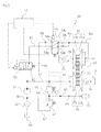
FIG. 2 is a circuit diagram of a hydraulic circuit according to a first preferred embodiment of the present invention during normal operation. -
FIG. 3 is a circuit diagram of the hydraulic circuit according to the first preferred embodiment of the present invention at the time of failure. -
FIG. 4(a) is a time chart showing hydraulic pressures at the time of failure. -
FIG. 4(b) is a time chart showing reduction ratios at the time of failure. -
FIG. 4(c) is a time chart showing vehicle speeds at the time of failure. -
FIG. 5(a) is a time chart showing hydraulic pressures at the time of restart. -
FIG. 5(b) is a time chart showing reduction ratios at the time of restart. -
FIG. 5(c) is a time chart for vehicle speeds at the time of restart. -
FIG. 6 is a circuit diagram of a hydraulic circuit according to a second preferred embodiment of the present invention at the time of failure. -
FIG. 7 is a circuit diagram of a hydraulic circuit according to a third preferred embodiment of the present invention during normal operation. -
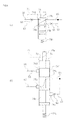
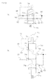
FIG. 8 (a) is a diagram including reference signs indicating a fail-safe valve according to the third preferred embodiment of the present invention during normal operation. -
FIG. 8(b) is a schematic diagram of the fail-safe valve ofFIG. 8(a) . -
FIG. 9(a) is a diagram including the reference signs indicating the fail-safe valve according to the third preferred embodiment of the present invention at the time of failure and when a pressure of a pressure change circuit is low. -
FIG. 9(b) is a schematic diagram of the fail-safe valve ofFIG. 9(a) . -
FIG. 10(a) is a diagram including the reference signs indicating the fail-safe valve according to the third preferred embodiment of the present invention at the time of failure and when the pressure of the pressure change circuit is high. -
FIG. 10(b) is a schematic diagram of the fail-safe valve ofFIG. 10(a) . - As illustrated in
FIG. 1 , a belt type continuously variable transmission (CVT) 30 according to the present preferred embodiment is provided in a driving unit 7 of amotorcycle 1. Themotorcycle 1 is provided as an example of a vehicle on which the belt type continuously variable transmission according to a preferred embodiment of the present invention is to be installed, and preferably is a scooter type motorcycle in the present preferred embodiment. However, a vehicle on which the belt type continuously variable transmission according to a preferred embodiment of the present invention is to be installed is not limited to a motorcycle. - As illustrated in
FIG. 1 , themotorcycle 1 includes a vehicle main body 9, a front wheel 2, and arear wheel 3 serving as a driving wheel. The vehicle main body 9 is provided with aseat 5 on which a rider sits. The front wheel 2 is supported by a lower end portion of a front fork 4. A handlebar 6 is attached to an upper end portion of the front fork 4. - The driving unit 7 provides a driving force to the
rear wheel 3. The driving unit 7 includes anengine 20 and theCVT 30. Theengine 20 includes acylinder 21 in which a not-illustrated piston is slidably contained, a crankshaft connected to the piston via a not-illustrated connecting rod, and acrankcase 23 in which the crankshaft is contained. TheCVT 30 is preferably disposed laterally of thecrankcase 23. - The
motorcycle 1 includes acontroller 10 that is arranged and programmed to control theengine 20 and theCVT 30, for example. An ECU (Electronic Control Unit), for example, may be used as thecontroller 10. Thecontroller 10 is preferably disposed above the driving unit 7. However, a position where thecontroller 10 is disposed is not limited to any particular position. - The
CVT 30 is preferably a hydraulically-controlled continuously variable transmission. As illustrated inFIG. 2 , theCVT 30 includes ahydraulic circuit 25. - The
CVT 30 includes aprimary pulley 31 serving as a first pulley, asecondary pulley 32 serving as a second pulley, and abelt 33 wound around theprimary pulley 31 and thesecondary pulley 32. Theprimary pulley 31 includes a fixedsheave 31b and amovable sheave 31a movable in an axial direction (i.e., rightward and leftward inFIG. 2 ) with respect to the fixedsheave 31b. Themovable sheave 31a and the fixedsheave 31b are connected to aprimary shaft 36. Themovable sheave 31a and the fixedsheave 31b rotate together with theprimary shaft 36. Theprimary shaft 36 is directly or indirectly connected to the crankshaft (not illustrated) of theengine 20. Theprimary shaft 36 rotates by receiving a torque of the crankshaft. Note that a portion of the crankshaft may constitute theprimary shaft 36. - The
secondary pulley 32 includes a fixedsheave 32b and amovable sheave 32a movable in the axial direction (i.e., rightward and leftward inFIG. 2 ) with respect to the fixedsheave 32b. Themovable sheave 32a and the fixedsheave 32b are connected to asecondary shaft 34. Thesecondary shaft 34 rotates together with themovable sheave 32a and the fixedsheave 32b. Thesecondary shaft 34 is directly or indirectly connected to therear wheel 3. Therear wheel 3 rotates by receiving a torque of thesecondary shaft 34. - In the present preferred embodiment, the
belt 33 is preferably a metal belt. However, thebelt 33 is not limited to a metal belt, but may be selected from other types of belts such as a resin belt. Thebelt 33 is located between themovable sheave 31a and the fixedsheave 31b of theprimary pulley 31, and between themovable sheave 32a and the fixedsheave 32b of thesecondary pulley 32. - A distance between the
movable sheave 31a and the fixedsheave 31b and a distance between themovable sheave 32a and the fixedsheave 32b are each changed, thus changing a reduction ratio of theCVT 30. When themovable sheave 31a is located closest to the fixedsheave 31b and themovable sheave 32a is located farthest from the fixedsheave 32b, the reduction ratio is in "OVERDRIVE" (i.e., at a minimum reduction ratio), which will hereinafter be referred to as "OD". Conversely, when themovable sheave 31a is located farthest from the fixedsheave 31b and themovable sheave 32a is located closest to the fixedsheave 32b, the reduction ratio is in "LOW" (i.e., at a maximum reduction ratio). The reduction ratio can be freely adjusted between "OD" and "LOW". - The reduction ratio is controlled by utilizing a hydraulic pressure. The
primary pulley 31 is provided with afirst oil chamber 41. Oil is supplied from thehydraulic circuit 25 to thefirst oil chamber 41 as appropriate, and is discharged from thefirst oil chamber 41 to thehydraulic circuit 25 as appropriate. Themovable sheave 31a is arranged so as to be axially moved in accordance with a hydraulic pressure of thefirst oil chamber 41. Themovable sheave 31a comes close to the fixedsheave 31b upon an increase in hydraulic pressure of thefirst oil chamber 41, and themovable sheave 31a moves away from the fixedsheave 31b upon a reduction in hydraulic pressure of thefirst oil chamber 41. The reduction ratio decreases upon an increase in hydraulic pressure of thefirst oil chamber 41, and the reduction ratio increases upon a reduction in hydraulic pressure of thefirst oil chamber 41. - The
secondary pulley 32 is provided with asecond oil chamber 42. Oil is supplied from thehydraulic circuit 25 to thesecond oil chamber 42 as appropriate, and is discharged from thesecond oil chamber 42 to thehydraulic circuit 25 as appropriate. Themovable sheave 32a is arranged so as to be axially moved in accordance with a hydraulic pressure of thesecond oil chamber 42. Themovable sheave 32a comes close to the fixedsheave 32b upon an increase in hydraulic pressure of thesecond oil chamber 42, and themovable sheave 32a moves away from the fixedsheave 32b upon a reduction in hydraulic pressure of thesecond oil chamber 42. The reduction ratio increases upon an increase in hydraulic pressure of thesecond oil chamber 42, and the reduction ratio decreases upon a reduction in hydraulic pressure of thesecond oil chamber 42. - Note that the
first oil chamber 41 may be provided integrally with themovable sheave 31a, or may be provided separately from themovable sheave 31a. For example, thefirst oil chamber 41 may be provided inside a hydraulic actuator provided separately from themovable sheave 31a. Similarly, thesecond oil chamber 42 may be provided integrally with themovable sheave 32a, or may be provided separately from themovable sheave 32a. For example, thesecond oil chamber 42 may be provided inside a hydraulic actuator provided separately from themovable sheave 32a. - Next, a configuration of the
hydraulic circuit 25 will be described. Thehydraulic circuit 25 includes atank 50 in which oil is stored, anoil pump 51, afirst control valve 53 serving as an example of a control valve that controls the hydraulic pressure of thefirst oil chamber 41, asecond control valve 56 serving as an example of a pressure reducing mechanism that controls the hydraulic pressure of thesecond oil chamber 42, and a fail-safe valve 54 serving as an example of a switching valve. - The
oil pump 51 is indirectly connected to the crankshaft of theengine 20 so as to be operated in conjunction with theengine 20. The higher the engine rotational speed, the higher the rotational speed of theoil pump 51, and the lower the engine rotational speed, the lower the rotational speed of theoil pump 51. Note that the engine rotational speed refers to the rotational speed of the crankshaft. A flow rate of oil discharged from theoil pump 51 is increased as the engine rotational speed is increased, and the flow rate of oil discharged from theoil pump 51 is reduced as the engine rotational speed is reduced. - A
suction circuit 60 through which thetank 50 and a suction-side portion of theoil pump 51 are connected to each other is provided with astrainer 52. A discharge-side portion of theoil pump 51 and thesecond oil chamber 42 communicate with each other via afirst circuit 61. - The fail-
safe valve 54 preferably includes an electromagnetic four-way valve, and includes afirst port 54a, asecond port 54b, athird port 54c and afourth port 54d. Thefirst circuit 61 and thefirst port 54a of the fail-safe valve 54 communicate with each other through asecond circuit 62. Thefirst control valve 53 is provided in thesecond circuit 62. Thefirst control valve 53 is preferably an electromagnetic pressure control valve that adjusts a downstream pressure. Thefirst control valve 53 receives a control signal from thecontroller 10 to control the hydraulic pressure of thefirst oil chamber 41 within a pressure range between given minimum and maximum pressures. When thefirst control valve 53 receives no control signal from thecontroller 10, i.e., when thefirst control valve 53 is not energized, a set pressure of thefirst control valve 53 is the maximum pressure. - The
second port 54b of the fail-safe valve 54 and thefirst oil chamber 41 communicate with each other through athird circuit 63. Thethird circuit 63 is provided with anorifice 55. - The
hydraulic circuit 25 includes alubrication circuit 80 serving as an example of a pressure change circuit that is opened toward a slidingportion 70 of theengine 20 or theCVT 30. Thelubrication circuit 80 is a circuit through which oil is supplied to the slidingportion 70. The slidingportion 70 is lubricated with oil supplied from thelubrication circuit 80. Thelubrication circuit 80 is provided with anorifice 59. - The
first circuit 61 and thelubrication circuit 80 communicate with each other through afourth circuit 64. Thesecond control valve 56 is provided in thefourth circuit 64. Thesecond control valve 56 is preferably an electromagnetic pressure control valve that adjusts an upstream pressure. Thesecond control valve 56 receives a control signal from thecontroller 10 to control the hydraulic pressure of thesecond oil chamber 42 within a pressure range between given minimum and maximum pressures. When thesecond control valve 56 receives no control signal from thecontroller 10, i.e., when thesecond control valve 56 is not energized, a set pressure of thesecond control valve 56 is the maximum pressure. - A portion of the
third circuit 63 located closer to thefirst oil chamber 41 than theorifice 55 and thethird port 54c of the fail-safe valve 54 communicate with each other through afifth circuit 65. Thefourth port 54d of the fail-safe valve 54 and a portion of thelubrication circuit 80 located upstream of theorifice 59 communicate with each other through asixth circuit 66. Thesixth circuit 66 is provided with anorifice 58. - The portion of the
lubrication circuit 80 located upstream of theorifice 59 and a portion of thesuction circuit 60 located downstream of thestrainer 52 communicate with each other through aseventh circuit 67. Theseventh circuit 67 is provided with arelief valve 57. When a hydraulic pressure of thelubrication circuit 80 exceeds an upper limit, therelief valve 57 allows some of the oil in thelubrication circuit 80 to flow out to thesuction circuit 60 so that the hydraulic pressure of thelubrication circuit 80 falls below the upper limit. Therelief valve 57 is arranged so as to be opened when the upstream hydraulic pressure reaches the upper limit, which is set in advance. - When the fail-
safe valve 54 receives a control signal from thecontroller 10, i.e., when the fail-safe valve 54 is energized, the fail-safe valve 54 enters a state (first state) in which thefirst port 54a and thethird port 54c communicate with each other and thesecond port 54b and thefourth port 54d do not communicate with each other. Conversely, when the fail-safe valve 54 receives no control signal from thecontroller 10, i.e., when the fail-safe valve 54 is not energized, the fail-safe valve 54 enters a state (second state) in which thefirst port 54a and thesecond port 54b communicate with each other and thethird port 54c and thefourth port 54d communicate with each other. - During normal operation, the control signal is supplied from the
controller 10 to thefirst control valve 53, thesecond control valve 56 and the fail-safe valve 54. As illustrated inFIG. 2 , the fail-safe valve 54 enters the state in which thefirst port 54a and thethird port 54c communicate with each other and thesecond port 54b and thefourth port 54d do not communicate with each other. Thefirst control valve 53 and thesecond control valve 56 control the hydraulic pressures of thefirst oil chamber 41 and thesecond oil chamber 42, respectively, thus controlling the reduction ratio of theCVT 30 to a given value. Thecontroller 10 controls the reduction ratio of theCVT 30 in accordance with an operating state of themotorcycle 1. - A portion of the oil discharged from the
oil pump 51 passes through thefirst control valve 53 to become oil having a given pressure. This oil passes through thefirst port 54a and thethird port 54c of the fail-safe valve 54, and is supplied to thefirst oil chamber 41. Therefore, the hydraulic pressure of thefirst oil chamber 41 is controlled to be a given pressure. The other portion of the oil discharged from theoil pump 51 is supplied to thesecond oil chamber 42 through thefirst circuit 61. The hydraulic pressure of thefirst circuit 61 is controlled to be a given pressure by thesecond control valve 56. Hence, the hydraulic pressure of thesecond oil chamber 42 is controlled to be a given pressure. Oil discharged from thesecond control valve 56 is supplied to thelubrication circuit 80, and is then supplied as lubricating oil to the slidingportion 70. The oil utilized as lubricating oil is collected into thetank 50. When the hydraulic pressure of thelubrication circuit 80 is higher than the upper limit, therelief valve 57 is opened, and a portion of the oil in thelubrication circuit 80 is sucked into theoil pump 51 through theseventh circuit 67. - Upon occurrence of a failure during operation, transmission of the control signal from the
controller 10 to thefirst control valve 53, thesecond control valve 56 and the fail-safe valve 54 is stopped. As used herein, the term "failure" refers to a state in which the hydraulic pressure (s) of thefirst oil chamber 41 and/or thesecond oil chamber 42 cannot be controlled, and as a consequence theCVT 30 cannot be properly controlled. The "failure" corresponds to, for example, a failure of thecontroller 10, a failure of thefirst control valve 53, a failure of thesecond control valve 56, a break in a signal line through which thecontroller 10 and thefirst control valve 53 are connected to each other, and a break in a signal line through which thecontroller 10 and thesecond control valve 56 are connected to each other. - Upon stoppage of transmission of the control signal from the
controller 10 to the fail-safe valve 54, the fail-safe valve 54 is switched to the state in which thefirst port 54a and thesecond port 54b communicate with each other and thethird port 54c and thefourth port 54d communicate with each other as illustrated inFIG. 3 . Upon stoppage of transmission of the control signal from thecontroller 10 to thefirst control valve 53 and thesecond control valve 56, the set pressure of the first control valve 53 (i.e., the hydraulic pressure of thesecond circuit 62, for example) becomes the maximum pressure, and the set pressure of the second control valve 56 (i.e., the hydraulic pressure of thefirst circuit 61, for example) becomes the maximum pressure. The set pressures of thefirst control valve 53 and thesecond control valve 56 are controlled to the maximum pressures at the time of failure in this manner in order to support thebelt 33 by theprimary pulley 31 and thesecondary pulley 32 as firmly as possible by increasing the hydraulic pressures of thefirst oil chamber 41 and thesecond oil chamber 42, so that thebelt 33 does not slide with respect to theprimary pulley 31 and thesecondary pulley 32. - Some of the oil discharged from the
oil pump 51 is reduced in pressure through thefirst control valve 53, and then passes through thefirst port 54a and thesecond port 54b of the fail-safe valve 54 to flow into thethird circuit 63. When the pressure of this oil is higher than the hydraulic pressure of thefirst oil chamber 41, this oil flows into thefirst oil chamber 41. For example, when the reduction ratio of theCVT 30 at the time of failure is small (e.g., in the case of "OD"), the hydraulic pressure of thefirst oil chamber 41 is low, and therefore, the oil passed through thefirst control valve 53 flows into thefirst oil chamber 41. As a result, the hydraulic pressure of thefirst oil chamber 41 increases. Note that a flow of the oil passed through thefirst port 54a and thesecond port 54b is reduced by theorifice 55, and therefore, an abrupt change in the pressure of thefirst oil chamber 41 is prevented. Consequently, an abrupt change in the reduction ratio is prevented. - The oil passed through the
first port 54a and thesecond port 54b of the fail-safe valve 54 flows through thefifth circuit 65, passes through thethird port 54c and thefourth port 54d of the fail-safe valve 54, and flows into thesixth circuit 66. Note that thesixth circuit 66 is provided with theorifice 58, thus preventing an excessive reduction in hydraulic pressure of a portion located upstream of theorifice 58, i.e., a component such as thefirst oil chamber 41. The hydraulic pressure of thefirst oil chamber 41 is maintained at a high level. - The oil of the
sixth circuit 66 is supplied to thelubrication circuit 80. When the hydraulic pressure of thelubrication circuit 80 exceeds the upper limit due to the flow of the oil of thesixth circuit 66 into thelubrication circuit 80, some of this oil flows into thesuction circuit 60 through therelief valve 57 and theseventh circuit 67. Accordingly, even when high-pressure oil flows into thelubrication circuit 80 through thesixth circuit 66, the hydraulic pressure of thelubrication circuit 80 will not be excessively increased. A smooth lubricating operation performed by thelubrication circuit 80 will not be hindered, and an excessive supply of oil to the slidingportion 70 will be prevented. -
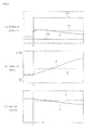
FIG. 4(a) is a time chart showing hydraulic pressure changes at the time of failure. InFIG. 4(a) , the horizontal axis represents time, and t1 denotes a time at which a failure has occurred. The same goes forFIGS. 4(b) and 4(c) . P1, P2 and P3 denote the hydraulic pressure of thefirst oil chamber 41, the hydraulic pressure of thesecond oil chamber 42, and the hydraulic pressure of thelubrication circuit 80, respectively. P1' denotes the hydraulic pressure of thefirst oil chamber 41 obtained in an example (hereinafter referred to as a "comparative example") where the fail-safe valve 54 and thesixth circuit 66 are omitted and thesecond circuit 62 and thethird circuit 63 are connected in series. Upon an occurrence of failure at t1 and stoppage of transmission of the control signal from thecontroller 10 to thefirst control valve 53, thesecond control valve 56, and the fail-safe valve 54, the set pressure of thefirst control valve 53 becomes the maximum pressure, and thus both of P1 and P1' increase. In the comparative example, the hydraulic pressure of thefirst oil chamber 41 substantially corresponds to the maximum pressure of thefirst control valve 53, and therefore, P1' remains constant at the maximum pressure. In the present preferred embodiment, since thesixth circuit 66 is provided with theorifice 58, P1 is temporarily higher than P1' immediately after the occurrence of failure, but in the course of time, the oil of thefirst oil chamber 41 is discharged to thelubrication circuit 80 through thesixth circuit 66 resulting in a gradual reduction in P1. Note that the set pressure of thesecond control valve 56 also becomes the maximum pressure at the time of failure, and therefore, P2 increases concurrently with the occurrence of failure and then remains constant. -
FIG. 4(b) is a time chart showing reduction ratios at the time of failure. R denotes a reduction ratio in the present preferred embodiment, and R' denotes a reduction ratio in the comparative example. As is evident fromFIG. 4(b) , R' abruptly changes but R moderately changes immediately after the occurrence of failure. It is also evident that upon lapse of a certain period of time after the occurrence of failure, R' does not change, but R continues to change and becomes higher than R' in the course of time. The reduction ratio R will be closer to "LOW" than the reduction ratio R'. Note that "OD" inFIG. 4(b) means "OVERDRIVE" and represents a state in which the reduction ratio is small. -
FIG. 4(c) is a time chart showing vehicle speeds of themotorcycle 1 at the time of failure. V denotes a vehicle speed in the present preferred embodiment, and V' denotes a vehicle speed in the comparative example. As is evident fromFIG. 4(c) , V' abruptly changes but V moderately changes immediately after the occurrence of failure. After a lapse of a certain period of time since the occurrence of failure, V becomes lower than V'. - As described above, according to the present preferred embodiment, changes in the reduction ratio and vehicle speed at the time of failure can be moderated.
-
FIG. 5(a) is a time chart showing hydraulic pressure changes obtained when themotorcycle 1 temporarily stops after the occurrence of failure and then makes a start (hereinafter referred to as "restart"). InFIG. 5 (a) , the horizontal axis represents time, and t2 denotes a time at which a restart is made. The same goes forFIGS. 5 (b) and 5 (c) . As is evident fromFIG. 5 (a) , P3 increases after the restart. This is because as the engine rotational speed increases, the rotational speed of theoil pump 51 increases, and the hydraulic pressure of thelubrication circuit 80 increases. No change is observed in P1', but in the present preferred embodiment, thefirst oil chamber 41 communicates with thelubrication circuit 80 via thesixth circuit 66, for example, and therefore, P1 increases as P3 increases. In this manner, P1 increases as the engine rotational speed increases. -
FIG. 5 (b) is a time chart showing reduction ratios at the time of restart. As is evident fromFIG. 5(b) , R' does not change and remains constant, but R decreases. This is because as the engine rotational speed increases, the hydraulic pressure P1 of thefirst oil chamber 41 increases, and themovable sheave 31a of theprimary pulley 31 comes close to the fixedsheave 31b thereof. In this manner, according to the present preferred embodiment, the vehicle restarts at the maximum reduction ratio and then the reduction ratio decreases during traveling. -
FIG. 5(c) is a time chart showing vehicle speeds at the time of restart. As is evident fromFIG. 5(c) , the degree of increase in V is greater than the degree of increase in V' (i.e., an acceleration of V is greater than that of V'), and therefore, favorable acceleration characteristics can be achieved in the present preferred embodiment. - As described thus far, according to the present preferred embodiment, the vehicle can restart at a large reduction ratio, and in addition, the reduction ratio decreases after the restart, thus making it possible to achieve favorable acceleration characteristics.
- According to the present preferred embodiment, the state of the fail-
safe valve 54 is switched at the time of failure, and thefirst oil chamber 41 communicates with thelubrication circuit 80, i.e., the circuit whose hydraulic pressure changes in accordance with the engine rotational speed. Therefore, the hydraulic pressure of thefirst oil chamber 41 changes in accordance with the engine rotational speed. At the time of restart when the engine rotational speed is low, the hydraulic pressure of thefirst oil chamber 41 is relatively low, and the reduction ratio is relatively large. Accordingly, a smooth start is enabled. During traveling, the engine rotational speed is higher than that at the time of restart, and the hydraulic pressure of thefirst oil chamber 41 is relatively increased, resulting in a relatively small reduction ratio. Accordingly, smooth traveling is enabled. Thus, according to the present preferred embodiment, even at the time of failure, the reduction ratio changes to some extent in accordance with the traveling state of themotorcycle 1, thus making it possible to achieve both a smooth start and smooth traveling. According to the present preferred embodiment, the vehicle is able to "limp-home" more easily and reliably. - The
hydraulic circuit 25 includes theoil pump 51 operated in conjunction with theengine 20. Thelubrication circuit 80 is a circuit that communicates with the discharge-side portion of theoil pump 51 via thesecond control valve 56 functioning as the pressure reducing mechanism. Theoil pump 51 and thesecond control valve 56 constitute a circuit whose hydraulic pressure changes in accordance with the engine rotational speed. According to the present preferred embodiment, the pressure change circuit whose hydraulic pressure changes in accordance with the engine rotational speed can be easily provided. - The
lubrication circuit 80 is a circuit originally provided to supply oil to the slidingportion 70. According to the present preferred embodiment, the existing circuit can be used as the circuit whose hydraulic pressure changes in accordance with the engine rotational speed. - The
third circuit 63 is provided with theorifice 55, and thus theorifice 55 reduces the flow of oil from thefirst control valve 53 toward thefirst oil chamber 41 at the time of failure. Therefore, the hydraulic pressure of thefirst oil chamber 41 is prevented from being abruptly changed at the time of failure. Accordingly, an abrupt change in the reduction ratio at the time of failure can be prevented. - The
lubrication circuit 80 communicates with thesuction circuit 60 via theseventh circuit 67, and theseventh circuit 67 is provided with therelief valve 57. Hence, even when the state of the fail-safe valve 54 is switched to cause a large amount of oil to flow into thelubrication circuit 80 at the time of failure, an excessive increase in hydraulic pressure of thelubrication circuit 80 is avoided. Accordingly, a smooth lubricating operation performed by thelubrication circuit 80 will not be hindered. - Since the
sixth circuit 66 is provided with theorifice 58, the hydraulic pressure of thefirst oil chamber 41 is maintained at a high level when the state of the fail-safe valve 54 is switched to cause thefirst oil chamber 41 and thelubrication circuit 80 to communicate with each other at the time of failure. When oil is discharged from thefirst oil chamber 41, a change in hydraulic pressure of thefirst oil chamber 41 can be moderated. - In the first preferred embodiment, the
lubrication circuit 80 is utilized as the pressure change circuit whose hydraulic pressure changes in accordance with the engine rotational speed. As illustrated inFIG. 6 , in the second preferred embodiment, a portion of thehydraulic circuit 25 according to the first preferred embodiment is modified, so that the pressure change circuit is provided separately from thelubrication circuit 80. - In the second preferred embodiment, a portion of the
first circuit 61 located adjacent to the discharge-side portion of theoil pump 51 is provided with anorifice 71. A portion of thefirst circuit 61 located between theoil pump 51 and theorifice 71, and a portion of thesuction circuit 60 located between theoil pump 51 and thestrainer 52 communicate with each other via an eighth circuit 68. The eighth circuit 68 is provided with an orifice 72 and anorifice 73. A hydraulic pressure of a portion of the eighth circuit 68 located between the orifice 72 and theorifice 73 increases as the engine rotational speed increases, and decreases as the engine rotational speed decreases. In the present preferred embodiment, the portion of the eighth circuit 68 located between the orifice 72 and theorifice 73 is utilized as the pressure change circuit. - In the first preferred embodiment, the
sixth circuit 66 connects thefourth port 54d of the fail-safe valve 54 and thelubrication circuit 80 to each other (seeFIG. 2 ). In the present preferred embodiment, one end of thesixth circuit 66 is connected to thefourth port 54d of the fail-safe valve 54, and the other end of thesixth circuit 66 is connected to the portion of the eighth circuit 68 located between the orifice 72 and theorifice 73. - Other features of the second preferred embodiment are similar to those of the first preferred embodiment, and therefore, description thereof will be omitted.
- Also in the second preferred embodiment, effects similar to those of the first preferred embodiment are obtained.
- As illustrated in
FIG. 7 , in the third preferred embodiment , a portion of thehydraulic circuit 25 according to the first preferred embodiment is modified, so that the reduction ratio at the time of failure is more variable than that in the first preferred embodiment. In the third preferred embodiment, a fail-safe valve 74 is provided instead of the fail-safe valve 54. -
FIG. 8 (a) is a diagram including reference signs indicating the fail-safe valve 74, andFIG. 8(b) is a conceptual diagram illustrating a configuration of the fail-safe valve 74. As illustrated inFIG. 8(b) , the fail-safe valve 74 is preferably an electromagnetic four-way valve, and includes afirst port 74a, asecond port 74b, athird port 74c and afourth port 74d. The fail-safe valve 74 is controlled by thecontroller 10. The fail-safe valve 74 includes asolenoid 74e that generates a downward force upon reception of a control signal from thecontroller 10, and aspool 74p that is pushed downward by thesolenoid 74e. Thespool 74p is provided with aland 74f. Note that as used herein, "upward" and "downward" directions merely mean directions indicated in the drawings, and do not necessarily mean actual directions when the fail-safe valve 74 is installed. Anoil chamber 76 is provided in the fail-safe valve 74, and thesixth circuit 66 and theoil chamber 76 communicate with each other via acommunication passage 75. - As illustrated in
FIG. 7 andFIG. 8(a) , similarly to the fail-safe valve 54 according to the first preferred embodiment , the fail-safe valve 74 enters, during normal operation, a state (first state) in which thefirst port 74a and thethird port 74c communicate with each other and thesecond port 74b and thefourth port 74d do not communicate with each other. - At the time of failure, transmission of the control signal from the
controller 10 to the fail-safe valve 74 is stopped, and the fail-safe valve 74 enters a non-energized state. As a result, thesolenoid 74e does not operate, and the force for pushing thespool 74p downward is lost, so that thespool 74p is urged upward by aspring 74s. Since theoil chamber 76 communicates with thesixth circuit 66 via thecommunication passage 75, the hydraulic pressure of theoil chamber 76 is equal to that of thesixth circuit 66. The hydraulic pressure of theoil chamber 76 acts on theland 74f, and thespool 74p receives the downward force due to the hydraulic pressure. Thesixth circuit 66 communicates with thelubrication circuit 80, and the hydraulic pressure of thesixth circuit 66 changes in accordance with the engine rotational speed. Hence, the hydraulic pressure of theoil chamber 76 also changes in accordance with the engine rotational speed. - When the engine rotational speed is low, the hydraulic pressure of the
oil chamber 76 is reduced. In this case, the force of the hydraulic pressure of theoil chamber 76 by which thespool 74p is pushed downward is smaller than the force of thespring 74s by which thespool 74p is pushed upward. As a result, as illustrated inFIG. 9 (b) , thespool 74p is moved to an uppermost position. Then, as illustrated inFIGS. 9(a) and 9(b) , the fail-safe valve 74 is switched to a state (second state) in which thefirst port 74a and thesecond port 74b communicate with each other and thethird port 74c and thefourth port 74d communicate with each other. - When the engine rotational speed is high, the hydraulic pressure of the
oil chamber 76 is increased. In this case, the force of the hydraulic pressure of theoil chamber 76 by which thespool 74p is pushed downward is relatively increased, which moves thespool 74p downward against the urging force of thespring 74s as illustrated inFIG. 10 (b) , for example. Theland 74 f is also moved downward upon downward movement of thespool 74p. Then, theland 74f closes a portion of, or the entire,fourth port 74d.FIGS. 10(a) and 10(b) illustrate a state in which the entirefourth port 74d is closed. An opening area of thefourth port 74d depends on the position of theland 74f, so that the higher the position of theland 74f, the greater the opening area, and the lower the position of theland 74f, the smaller the opening area. Hence, the opening area of thefourth port 74d changes in accordance with the pressures of thesixth circuit 66 and theoil chamber 76. - When the engine rotational speed is relatively low, the hydraulic pressures of the
sixth circuit 66 and theoil chamber 76 are reduced, and therefore, the opening area of thefourth port 74d is increased. When the opening area of thefourth port 74d is increased, the amount of oil discharged from thefirst oil chamber 41 through thethird port 74c and thefourth port 74d is increased. Hence, the hydraulic pressure of thefirst oil chamber 41 is reduced, and the reduction ratio of theCVT 30 is increased. - When the engine rotational speed is relatively high, the hydraulic pressures of the
sixth circuit 66 and theoil chamber 76 are increased, and therefore, the opening area of thefourth port 74d is reduced. When the opening area of thefourth port 74d is reduced, the amount of oil discharged from thefirst oil chamber 41 through thethird port 74c and thefourth port 74d is reduced. Hence, the hydraulic pressure of thefirst oil chamber 41 is increased, and the reduction ratio of theCVT 30 is reduced. - According to the present preferred embodiment, the opening area of the
fourth port 74d changes not only in accordance with a change in the hydraulic pressure of thelubrication circuit 80, but also in accordance with this change in hydraulic pressure, the hydraulic pressure of thefirst oil chamber 41 can be more variable. Accordingly, the reduction ratio can be more variable. According to the present preferred embodiment, when the engine rotational speed is increased, the reduction ratio can be further reduced, thus allowing the reduction ratio to assume a more suitable value for high speed traveling. Accordingly, the vehicle is able to "limp-home" even more easily and reliably. - According to various preferred embodiments of the present invention, even when a reduction ratio of a CVT cannot be controlled due to a failure in a controller, for example, a vehicle is able to start and travel smoothly. Consequently, preferred embodiments of the present invention can provide a belt type continuously variable transmission that enables the vehicle to "limp-home" easily and reliably.
-
- 1
- motorcycle (vehicle)
- 20
- engine
- 25
- hydraulic circuit
- 30
- belt type continuously variable transmission (CVT)
- 31
- primary pulley (first pulley)
- 32
- secondary pulley (second pulley)
- 33
- belt
- 41
- first oil chamber
- 42
- second oil chamber
- 51
- oil pump
- 53
- first control valve (control valve)
- 56
- second control valve (pressure reducing mechanism)
- 54
- fail-safe valve (switching valve)
- 80
- lubrication circuit (pressure change circuit)
Claims (10)
- A belt type continuously variable transmission to be installed on a vehicle including an engine, the belt type continuously variable transmission comprising:a first pulley which includes a pair of first sheaves facing each other and a first oil chamber that contains oil and in which a distance between the pair of first sheaves is adjusted by a hydraulic pressure of the first oil chamber so that the distance between the pair of first sheaves decreases as the hydraulic pressure of the first oil chamber increases;a second pulley including a pair of second sheaves facing each other;a belt wound around the first pulley and the second pulley; anda hydraulic circuit connected to the first oil chamber; whereinthe hydraulic circuit includes:a control valve that controls the hydraulic pressure of the first oil chamber;a pressure change circuit having a hydraulic pressure that changes in accordance with a rotational speed of the engine so that a higher rotational speed of the engine results in a higher hydraulic pressure in the pressure change circuit; anda switching valve that is switched between a first state in which the control valve and the first oil chamber communicate with each other and a second state in which at least the first oil chamber and the pressure change circuit communicate with each other.
- The belt type continuously variable transmission according to Claim 1, wherein the hydraulic circuit further includes an oil pump that operates in accordance with the rotational speed of the engine, and the pressure change circuit communicates with a discharge-side portion of the oil pump via a pressure reducing mechanism.
- The belt type continuously variable transmission according to Claim 2, wherein the pressure change circuit opens to a sliding portion of the engine or a sliding portion of the belt type continuously variable transmission.
- The belt type continuously variable transmission according to Claim 3, wherein the hydraulic circuit further includes:another circuit through which the pressure change circuit and a suction-side portion of the oil pump communicate with each other; anda relief valve provided in the another circuit and that opens when the hydraulic pressure of the pressure change circuit exceeds an upper limit.
- The belt type continuously variable transmission according to Claim 1, wherein the hydraulic circuit further includes an orifice that reduces a flow of oil from the first oil chamber toward the pressure change circuit when the switching valve is set to the second state.
- The belt type continuously variable transmission according to Claim 1, further comprising a controller programmed to transmit a control signal to each of the control valve and the switching valve; wherein
the control valve is arranged so as to control the hydraulic pressure of the first oil chamber within a pressure range between minimum and maximum pressures upon receipt of the control signal from the controller, and so as to control the hydraulic pressure of the first oil chamber to the maximum pressure when the control valve receives no control signal from the controller;
the first state is a state in which the control valve and the first oil chamber communicate with each other and the first oil chamber and the pressure change circuit do not communicate with each other;
the second state is a state in which the control valve and the first oil chamber communicate with each other and the first oil chamber and the pressure change circuit communicate with each other; and
the switching valve is arranged so that the switching valve is set to the first state upon receipt of the control signal from the controller, and is set to the second state when the switching valve receives no control signal from the controller. - The belt type continuously variable transmission according to Claim 6, wherein the hydraulic circuit further includes an orifice that reduces a flow of oil from the control valve toward the first oil chamber when the switching valve is set to the second state.
- The belt type continuously variable transmission according to claim 1, wherein an area of a flow passage of the switching valve changes in accordance with a magnitude of the hydraulic pressure of the pressure change circuit so that a higher hydraulic pressure of the pressure change circuit results in a smaller area of the flow passage from the first oil chamber toward the pressure change circuit.
- The belt type continuously variable transmission according to Claim 1, wherein
the second pulley includes a second oil chamber that contains oil;
the pressure change circuit opens to a sliding portion of the engine or a sliding portion of the belt type continuously variable transmission;
the switching valve is an electromagnetic four-way valve including first, second, third and fourth ports;
the hydraulic circuit further includes:an oil pump that operates in accordance with the rotational speed of the engine;a first circuit through which a discharge-side portion of the oil pump and the second oil chamber communicate with each other;a second circuit through which the first circuit and the first port of the four-way valve communicate with each other, the second circuit including with the control valve;a third circuit through which the second port of the four-wayvalve and the first oil chamber communicate with each other, the third circuit including an orifice;a fourth circuit through which the first circuit and the pressure change circuit communicate with each other, the fourth circuit including another control valve that controls a hydraulic pressure of the second oil chamber;a fifth circuit through which a portion of the third circuit, located closer to the first oil chamber than the orifice, and the third port of the four-way valve communicate with each other; anda sixth circuit through which the fourth port of the four-way valve and the pressure change circuit communicate with each other, the sixth circuit including an orifice; andthe four-way valve is arranged so that the first port and the third port communicate with each other and the second port and the fourth port do not communicate with each other when the four-way valve is energized, and so that the first port and the second port communicate with each other and the third port and the fourth port communicate with each other when the four-way valve is not energized. - A vehicle comprising the belt type continuously variable transmission according to any one of Claims 1 to 9.
Applications Claiming Priority (2)
| Application Number | Priority Date | Filing Date | Title |
|---|---|---|---|
| JP2011038479 | 2011-02-24 | ||
| PCT/JP2011/078891 WO2012114612A1 (en) | 2011-02-24 | 2011-12-14 | Belt-type continuously variable transmission and vehicle with same |
Publications (1)
| Publication Number | Publication Date |
|---|---|
| EP2679868A1 true EP2679868A1 (en) | 2014-01-01 |
Family
ID=46720414
Family Applications (1)
| Application Number | Title | Priority Date | Filing Date |
|---|---|---|---|
| EP11859060.3A Withdrawn EP2679868A1 (en) | 2011-02-24 | 2011-12-14 | Belt-type continuously variable transmission and vehicle with same |
Country Status (4)
| Country | Link |
|---|---|
| US (1) | US20130323017A1 (en) |
| EP (1) | EP2679868A1 (en) |
| JP (1) | JP5735628B2 (en) |
| WO (1) | WO2012114612A1 (en) |
Cited By (1)
| Publication number | Priority date | Publication date | Assignee | Title |
|---|---|---|---|---|
| CN112628391A (en) * | 2019-10-07 | 2021-04-09 | 本田技研工业株式会社 | Hydraulic control device and hydraulic control method for continuously variable transmission |
Families Citing this family (4)
| Publication number | Priority date | Publication date | Assignee | Title |
|---|---|---|---|---|
| US10704680B2 (en) * | 2015-03-20 | 2020-07-07 | Jatco Ltd | Transmission control device and transmission control method |
| US10697536B2 (en) * | 2015-03-20 | 2020-06-30 | Jatco Ltd | Transmission control device and transmission control method |
| JP6241445B2 (en) * | 2015-04-17 | 2017-12-06 | トヨタ自動車株式会社 | Power transmission control device |
| CN112096853B (en) * | 2020-09-11 | 2021-11-09 | 陕西法士特齿轮有限责任公司 | Safety valve mechanism, system and control method for hydraulic automatic gear shifting system |
Family Cites Families (9)
| Publication number | Priority date | Publication date | Assignee | Title |
|---|---|---|---|---|
| JPS6053257A (en) * | 1983-08-31 | 1985-03-26 | Fuji Heavy Ind Ltd | Electronic controller for stepless transmission |
| JP3105037B2 (en) * | 1991-09-06 | 2000-10-30 | 富士重工業株式会社 | Starting clutch cooling device for vehicles |
| JP3265882B2 (en) | 1994-12-22 | 2002-03-18 | 日産自動車株式会社 | Transmission control device for belt type CVT |
| JPH09105457A (en) * | 1995-08-04 | 1997-04-22 | Fuji Heavy Ind Ltd | Controller for continuously variable transmission |
| JP4164787B2 (en) | 2000-03-29 | 2008-10-15 | スズキ株式会社 | Gear ratio control device for continuously variable transmission |
| JP4101445B2 (en) * | 2000-07-24 | 2008-06-18 | ジヤトコ株式会社 | Control device for continuously variable transmission |
| JP2004169895A (en) | 2002-11-22 | 2004-06-17 | Suzuki Motor Corp | Control device for continuously variable transmission |
| JP2006316819A (en) | 2005-05-10 | 2006-11-24 | Toyota Motor Corp | Hydraulic control device |
| JP4952754B2 (en) | 2009-08-12 | 2012-06-13 | セイコーエプソン株式会社 | Liquid ejecting apparatus, scalpel for operation, and method for controlling liquid ejecting apparatus |
-
2011
- 2011-12-14 WO PCT/JP2011/078891 patent/WO2012114612A1/en not_active Ceased
- 2011-12-14 JP JP2013500842A patent/JP5735628B2/en not_active Expired - Fee Related
- 2011-12-14 US US13/985,926 patent/US20130323017A1/en not_active Abandoned
- 2011-12-14 EP EP11859060.3A patent/EP2679868A1/en not_active Withdrawn
Non-Patent Citations (1)
| Title |
|---|
| See references of WO2012114612A1 * |
Cited By (2)
| Publication number | Priority date | Publication date | Assignee | Title |
|---|---|---|---|---|
| CN112628391A (en) * | 2019-10-07 | 2021-04-09 | 本田技研工业株式会社 | Hydraulic control device and hydraulic control method for continuously variable transmission |
| CN112628391B (en) * | 2019-10-07 | 2022-04-19 | 本田技研工业株式会社 | Hydraulic control device and hydraulic control method for continuously variable transmission |
Also Published As
| Publication number | Publication date |
|---|---|
| US20130323017A1 (en) | 2013-12-05 |
| JPWO2012114612A1 (en) | 2014-07-07 |
| WO2012114612A1 (en) | 2012-08-30 |
| JP5735628B2 (en) | 2015-06-17 |
Similar Documents
| Publication | Publication Date | Title |
|---|---|---|
| JP5445045B2 (en) | Hydraulic control device for automatic transmission | |
| US8825318B2 (en) | Control device and control method for automatic transmission | |
| CN105984455B (en) | The control device of vehicle | |
| EP2431635B1 (en) | Hydraulic device for stepless transmission and stepless transmission | |
| CN103339420B (en) | Hydraulic control device | |
| US20130323017A1 (en) | Belt type continuously variable transmission and vehicle including the same | |
| US7975474B2 (en) | Hydraulic system | |
| US8589039B2 (en) | Control device for automatic transmission and control method therefor | |
| US8753247B2 (en) | Two-wheeled motor vehicle | |
| US10274075B2 (en) | Hydraulic control apparatus | |
| CN112815055B (en) | Control device of continuously variable transmission | |
| US8894521B2 (en) | Power transmission device and vehicle in which power transmission device is installed | |
| JP6203888B2 (en) | Vehicle control device | |
| JP4680615B2 (en) | Shift control device for continuously variable transmission | |
| JP2007071272A (en) | Shift control device for continuously variable transmission | |
| JP2005282694A (en) | Vehicle control apparatus equipped with continuously variable transmission | |
| JP2014043876A (en) | Hydraulic supply device | |
| JP4745765B2 (en) | Shift control device for continuously variable transmission | |
| JP2006307926A (en) | Shift control device for continuously variable transmission | |
| KR100836918B1 (en) | Line pressure controller of continuously variable transmission for vehicle | |
| JP4164787B2 (en) | Gear ratio control device for continuously variable transmission | |
| WO2010064307A1 (en) | Hydraulic device of stepless transmission | |
| JP2012021469A (en) | Engine lubricating device | |
| JP2012092891A (en) | Hydraulic control apparatus | |
| JP2019219023A (en) | Vehicle power transmission device |
Legal Events
| Date | Code | Title | Description |
|---|---|---|---|
| PUAI | Public reference made under article 153(3) epc to a published international application that has entered the european phase |
Free format text: ORIGINAL CODE: 0009012 |
|
| 17P | Request for examination filed |
Effective date: 20130826 |
|
| AK | Designated contracting states |
Kind code of ref document: A1 Designated state(s): AL AT BE BG CH CY CZ DE DK EE ES FI FR GB GR HR HU IE IS IT LI LT LU LV MC MK MT NL NO PL PT RO RS SE SI SK SM TR |
|
| DAX | Request for extension of the european patent (deleted) | ||
| STAA | Information on the status of an ep patent application or granted ep patent |
Free format text: STATUS: THE APPLICATION HAS BEEN WITHDRAWN |
|
| 18W | Application withdrawn |
Effective date: 20160617 |