EP2679789A1 - Procédé d'arrêt d'un moteur à combustion interne hybride pneumatique - Google Patents
Procédé d'arrêt d'un moteur à combustion interne hybride pneumatique Download PDFInfo
- Publication number
- EP2679789A1 EP2679789A1 EP13169228.7A EP13169228A EP2679789A1 EP 2679789 A1 EP2679789 A1 EP 2679789A1 EP 13169228 A EP13169228 A EP 13169228A EP 2679789 A1 EP2679789 A1 EP 2679789A1
- Authority
- EP
- European Patent Office
- Prior art keywords
- engine
- stopping
- piston
- combustion chamber
- gas
- Prior art date
- Legal status (The legal status is an assumption and is not a legal conclusion. Google has not performed a legal analysis and makes no representation as to the accuracy of the status listed.)
- Granted
Links
- 238000002485 combustion reaction Methods 0.000 title claims abstract description 43
- 238000000034 method Methods 0.000 title claims abstract description 25
- 238000012937 correction Methods 0.000 claims abstract description 4
- 230000006835 compression Effects 0.000 claims description 6
- 238000007906 compression Methods 0.000 claims description 6
- 238000004891 communication Methods 0.000 claims description 4
- 238000009396 hybridization Methods 0.000 abstract description 13
- 239000007789 gas Substances 0.000 description 24
- 239000000446 fuel Substances 0.000 description 7
- 230000000694 effects Effects 0.000 description 3
- 238000002347 injection Methods 0.000 description 3
- 239000007924 injection Substances 0.000 description 3
- 239000000203 mixture Substances 0.000 description 3
- 239000000567 combustion gas Substances 0.000 description 2
- 238000013459 approach Methods 0.000 description 1
- 238000006073 displacement reaction Methods 0.000 description 1
- 238000012986 modification Methods 0.000 description 1
- 230000004048 modification Effects 0.000 description 1
- 238000010791 quenching Methods 0.000 description 1
- 239000000243 solution Substances 0.000 description 1
Images
Classifications
-
- F—MECHANICAL ENGINEERING; LIGHTING; HEATING; WEAPONS; BLASTING
- F02—COMBUSTION ENGINES; HOT-GAS OR COMBUSTION-PRODUCT ENGINE PLANTS
- F02D—CONTROLLING COMBUSTION ENGINES
- F02D41/00—Electrical control of supply of combustible mixture or its constituents
- F02D41/02—Circuit arrangements for generating control signals
- F02D41/04—Introducing corrections for particular operating conditions
- F02D41/042—Introducing corrections for particular operating conditions for stopping the engine
-
- F—MECHANICAL ENGINEERING; LIGHTING; HEATING; WEAPONS; BLASTING
- F02—COMBUSTION ENGINES; HOT-GAS OR COMBUSTION-PRODUCT ENGINE PLANTS
- F02B—INTERNAL-COMBUSTION PISTON ENGINES; COMBUSTION ENGINES IN GENERAL
- F02B21/00—Engines characterised by air-storage chambers
-
- F—MECHANICAL ENGINEERING; LIGHTING; HEATING; WEAPONS; BLASTING
- F02—COMBUSTION ENGINES; HOT-GAS OR COMBUSTION-PRODUCT ENGINE PLANTS
- F02D—CONTROLLING COMBUSTION ENGINES
- F02D17/00—Controlling engines by cutting out individual cylinders; Rendering engines inoperative or idling
- F02D17/04—Controlling engines by cutting out individual cylinders; Rendering engines inoperative or idling rendering engines inoperative or idling, e.g. caused by abnormal conditions
-
- F—MECHANICAL ENGINEERING; LIGHTING; HEATING; WEAPONS; BLASTING
- F02—COMBUSTION ENGINES; HOT-GAS OR COMBUSTION-PRODUCT ENGINE PLANTS
- F02N—STARTING OF COMBUSTION ENGINES; STARTING AIDS FOR SUCH ENGINES, NOT OTHERWISE PROVIDED FOR
- F02N19/00—Starting aids for combustion engines, not otherwise provided for
- F02N19/005—Aiding engine start by starting from a predetermined position, e.g. pre-positioning or reverse rotation
-
- F—MECHANICAL ENGINEERING; LIGHTING; HEATING; WEAPONS; BLASTING
- F02—COMBUSTION ENGINES; HOT-GAS OR COMBUSTION-PRODUCT ENGINE PLANTS
- F02N—STARTING OF COMBUSTION ENGINES; STARTING AIDS FOR SUCH ENGINES, NOT OTHERWISE PROVIDED FOR
- F02N19/00—Starting aids for combustion engines, not otherwise provided for
- F02N19/005—Aiding engine start by starting from a predetermined position, e.g. pre-positioning or reverse rotation
- F02N2019/008—Aiding engine start by starting from a predetermined position, e.g. pre-positioning or reverse rotation the engine being stopped in a particular position
-
- F—MECHANICAL ENGINEERING; LIGHTING; HEATING; WEAPONS; BLASTING
- F02—COMBUSTION ENGINES; HOT-GAS OR COMBUSTION-PRODUCT ENGINE PLANTS
- F02N—STARTING OF COMBUSTION ENGINES; STARTING AIDS FOR SUCH ENGINES, NOT OTHERWISE PROVIDED FOR
- F02N9/00—Starting of engines by supplying auxiliary pressure fluid to their working chambers
- F02N9/04—Starting of engines by supplying auxiliary pressure fluid to their working chambers the pressure fluid being generated otherwise, e.g. by compressing air
Definitions
- the invention relates to a method of stopping a combustion engine.
- the position of the pistons of a combustion engine at a standstill has a significant influence on the quality of the next restart of this engine. It is particularly difficult to manage the stopping position of the pistons of an engine.
- the invention aims to solve one or more of these disadvantages in the case where the combustion engine is associated with a gas tank under pressure.
- the invention relates to a method of stopping an internal combustion engine comprising at least one combustion chamber in which is mounted a piston, the engine being associated with a pressurized gas tank with which it can be put into operation. communication, characterized in that the stop position taken by the piston once the shutdown process is completed results from the sending of gas from the tank into the combustion chamber.
- the stopping method comprises a stopping phase of the engine following which the engine is stopped, and a correction phase during which pressurized gas is sent into the chamber. when the engine is stopped and disengaged.
- the stopping method comprises a stopping phase of the engine following which the engine is stopped, pressurized gas being sent into the combustion chamber, during the staging phase. when stopped, when the piston is in the compression phase.
- the gas is introduced into the combustion chamber before stopping the piston in order to slow it down and immobilize it at the right position.
- the stop position is determined by a control system so as to facilitate a next start.
- the introduction of the gas into the combustion chamber is achieved by the opening of a valve connected to the gas tank.
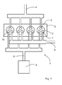
- the figure 1 represents a motor unit 1 of a motor vehicle, the engine group 1 comprising an internal combustion engine 2 provided with at least one combustion chamber 3 (here, four combustion chambers).
- each combustion chamber 3 is slidably mounted a piston whose movement provides the energy produced by the engine 2.
- Each combustion chamber 3 is associated with a fuel injection device and valves allowing in particular the introduction of the air and the exhaust of combustion gases resulting from the combustion of a mixture of air and fuel.
- the engine group 1 comprises an air intake line 4 which allows air to supply the various combustion chambers via intake valves 5.
- each combustion chamber 3 comprises two intake valves 5.
- the engine group 1 also comprises an exhaust line 6 which allows the evacuation of combustion gases from the various combustion chambers 3 via exhaust valve 7.
- each combustion chamber 3 comprises a combustion valve 3. exhaust 6.
- the motor unit further comprises a pressurized gas tank 8 which is connected to the engine via a pneumatic hybridization duct 9, pneumatic hybridization valves 10 allowing a selective communication of each combustion chamber. 3 with the tank 8 via the pneumatic hybridization duct 9.
- each combustion chamber 3 comprises a pneumatic hybridization valve 10.
- the pressurized gas contained in the tank 8 is sent or no, according to the vehicle life situations, in one or more combustion chambers 3 synchronously with the cycle of the engine 2, in order to increase the thrust exerted on the piston or to improve the mixture of air and fuel .
- the pressurized gas tank 8 is supplied by one or more combustion chambers 3 during their respective compression phases, advantageously when no fuel is introduced into the chambers in order to minimize the energy losses caused by filling the tank 8. this fact, the gas contained in the tank is mainly composed of air.
- the opening of the pneumatic hybridization valve 10 can be carried out at different engine cycle times (in the compression phase for filling the tank 8 and for improving the mixture of air and fuel by the introduction of gas under pressure, post combustion combustion phase for the use of pressurized gas as additional mechanical force exerted on the piston).
- the movement control device of the pneumatic hybridization valve 10 is configured to force the holding in the closed position of the corresponding pneumatic hybridization valve when the life situation of the vehicle does not correspond to a situation of placing the tank in communication with one another.
- a combustion chamber could include two: one opening in the intake phases, the other in the phases each of which is controlled by a control device that can force them into the closed position.
- the gases contained in the tank 8 are sent into at least one of the combustion chambers 3 so as to position the corresponding piston in a final stop position, that is to say the position resulting from the combination of the effect due to the stopping of the engine following the initialization of a method of stopping the engine and the effect due to the pressure exerted by the gas on the piston following the sending of this gas from the tank 8 also following the initialization of the method of stopping the engine 2.
- the stop position taken by the piston once the shutdown process is completed results from the sending of gas from the tank 8 in the combustion chamber 3.
- the movement control device of the pneumatic hybridization valve 8 drives the pneumatic hybridization valve into its open position once the motor 2 shutdown process is initialized.
- the final stopping position of the piston is determined by a control system so as to facilitate and optimize the next start of the engine 2. It is thus possible to restart the engine 2 better in terms of time (particularly useful for reboots the "stop and start” type) and energy cost (better compression and better combustion).
- the invention is usable for any type of restart, both for a restart with fuel injection ("thermal” mode) and for a restart without fuel injection (“air” mode).
- the method of stopping the engine 2 comprises a stopping phase of the engine following which the engine is stopped and the piston is in a temporary stopping position, followed by a phase correction of the position of the piston during which the pressurized gas is sent into the combustion chamber 3 once the engine 2 stopped and disengaged. The gas thus moves the piston from its temporary stop position to its final stop position.
- the method of the engine 2 comprises a stopping phase of the engine following which the engine is stopped and the piston is in its final stop position, the pressurized gas being sent to the engine. combustion chamber during this shutdown phase when the piston is in the compression phase (that is, when the piston approaches the valves). As a result, the gas counteracts the movement of the piston.
- the amount of air is determined according to the mechanical work to be provided on the piston to immobilize it in its final stop position.
- the combustion chamber 3 in which the compressed air is introduced depends on the position and the movement of the corresponding piston, the action on a piston provoking, whatever the effect, on the movement of all the pistons of the engine 2.
Landscapes
- Engineering & Computer Science (AREA)
- Chemical & Material Sciences (AREA)
- Combustion & Propulsion (AREA)
- Mechanical Engineering (AREA)
- General Engineering & Computer Science (AREA)
- Output Control And Ontrol Of Special Type Engine (AREA)
Abstract
Description
- L'invention concerne un procédé d'arrêt d'un moteur à combustion.
- La position des pistons d'un moteur à combustion à l'arrêt a une influence non négligeable sur la qualité du prochain redémarrage de ce moteur. Il est particulièrement délicat de gérer la position d'arrêt des pistons d'un moteur.
- Une solution actuellement utilisée est de fermer l'admission d'air du moteur une fois le procédé d'arrêt initialisé afin d'étouffer le moteur. Cependant, la justesse de la position d'arrêt définitive du piston par rapport à sa position idéale est difficile à obtenir, les pistons étant définitivement immobiles une fois le moteur arrêté.
- L'invention vise à résoudre un ou plusieurs de ces inconvénients dans le cas où le moteur à combustion est associé à un réservoir de gaz sous pression.
- L'invention porte sur un procédé d'arrêt d'un moteur à combustion interne comprenant au moins une chambre à combustion dans laquelle est monté mobile un piston, le moteur étant associé à un réservoir à gaz sous pression avec lequel il peut être mis en communication, caractérisé en ce que la position d'arrêt prise par le piston une fois le procédé d'arrêt terminé résulte de l'envoi de gaz provenant du réservoir dans la chambre à combustion.
- De ce fait, il est possible, sans apporter de modification significative au groupe moteur à hybridation pneumatique, d'avoir un système permettant un positionnement précis des pistons du moteur une fois ce dernier arrêté. Les seules modifications à apporter concernent le système de contrôle commande du moteur.
- Selon un premier mode de réalisation, le procédé d'arrêt comprend une phase de mise à l'arrêt du moteur à la suite de laquelle le moteur est arrêté, et une phase de correction lors de laquelle du gaz sous pression est envoyé dans la chambre de combustion une fois le moteur arrêté et débrayé.
- Selon ce mode, l'arrêt naturel du moteur est suivi par un déplacement correctif de la position du piston par l'introduction de gaz dans la chambre de combustion correspondante.
- Selon un second mode de réalisation, le procédé d'arrêt comprend une phase de mise à l'arrêt du moteur à la suite de laquelle le moteur est arrêté, du gaz sous pression étant envoyé dans la chambre de combustion, pendant la phase de mise à l'arrêt, quand le piston est en phase de compression.
- Selon ce mode, le gaz est introduit dans la chambre de combustion avant l'arrêt du piston afin de le ralentir et de l'immobiliser à la bonne position.
- Selon un troisième mode de réalisation, la position d'arrêt est déterminée par un système de contrôle commande de façon à faciliter un prochain démarrage.
- Selon un quatrième mode de réalisation, l'introduction du gaz dans la chambre de combustion est réalisée par l'ouverture d'une soupape reliée au réservoir à gaz.
- D'autres caractéristiques et avantages de l'invention ressortiront clairement de la description qui en est faite ci-après, à titre indicatif et nullement limitatif, en référence aux dessins annexés, dans lesquels :
- la
figure 1 illustre un bloc moteur comprenant un réservoir de gaz sous pression 8 au quel peut être appliqué un procédé d'arrêt du moteur conforme à la présente invention. - La
figure 1 représente un groupe moteur 1 d'un véhicule automobile, le groupe moteur 1 comprenant un moteur 2 à combustion interne muni d'au moins une chambre de combustion 3 (ici, de quatre chambres de combustion). Dans chaque chambre de combustion 3 est monté coulissant un piston dont le mouvement fourni l'énergie produite par le moteur 2. A chaque chambre de combustion 3 sont associés un dispositif d'injection de carburant et des soupapes permettant notamment l'introduction de l'air et l'échappement des gaz de combustion résultant de la combustion d'un mélange d'air et de carburant. - Le groupe moteur 1 comprend une ligne d'admission d'air 4 qui permet d'alimenter en air les différentes chambres de combustion par l'intermédiaire de soupapes d'admission 5. Ici, chaque chambre de combustion 3 comprend deux soupapes d'admission 5.
- Le groupe moteur 1 comprend également une ligne d'échappement 6 qui permet l'évacuation des gaz de combustion hors des différentes chambres de combustion 3 par l'intermédiaire de soupape d'échappement 7. Ici, chaque chambre de combustion 3 comprend une soupape d'échappement 6.
- Le groupe moteur comprend de plus un réservoir de gaz sous pression 8 qui est relié au moteur par l'intermédiaire d'une conduite d'hybridation pneumatique 9, des soupapes d'hybridation pneumatique 10 permettant une mise en communication sélective de chaque chambre de combustion 3 avec le réservoir 8 par l'intermédiaire de la conduite d'hybridation pneumatique 9. Ici, chaque chambre de combustion 3 comprend une soupape d'hybridation pneumatique 10.
- De façon classique pour une hybridation pneumatique d'un moteur à combustion, le gaz sous pression contenu dans le réservoir 8 est envoyé ou non, selon les situations de vie du véhicule, dans une ou plusieurs chambres de combustion 3 de façon synchronisée avec le cycle du moteur 2, afin d'augmenter la poussée exercée sur le piston ou d'améliorer le mélange d'air et de carburant. Le réservoir de gaz sous pression 8 est alimenté par une ou plusieurs chambres de combustion 3 pendant leurs phases de compression respectives, avantageusement quand aucun carburant n'est introduit dans les chambres afin de minimiser les pertes énergétiques causées par le remplissage du réservoir 8. De ce fait, le gaz contenu dans le réservoir est principalement composé d'air.
- Ainsi, l'ouverture d'une la soupape d'hybridation pneumatique 10 peut être réalisée à différents temps du cycle du moteur (en phase de compression pour le remplissage du réservoir 8 et pour l'amélioration du mélange d'air et de carburant par l'introduction de gaz sous pression, en phase de détente post combustion pour l'utilisation du gaz sous pression comme force mécanique supplémentaire exercée sur le piston). Le dispositif de commande du mouvement de la soupape d'hybridation pneumatique 10 est configuré pour forcer le maintien en position fermée de la soupape d'hybridation pneumatique correspondante quand la situation de vie du véhicule ne correspondent pas à une situation de mise en communication du réservoir 8 avec le moteur 2. Au lieu de n'avoir qu'une seule soupape d'hybridation pneumatique, une chambre de combustion pourrait en comprendre deux : l'une s'ouvrant dans les phases d'admission, l'autre dans les phases de détente, chacune étant commandée par un dispositif de commande pouvant les forcer en position fermée.
- Conformément à l'invention, les gaz contenus dans le réservoir 8 sont envoyés dans au moins l'une des chambres de combustion 3 de façon à positionner le piston correspondant dans une position d'arrêt définitive, c'est-à-dire la position d'arrêt résultant de la combinaison de l'effet dû à l'arrêt du moteur suite à l'initialisation d'un procédé d'arrêt du moteur et de l'effet dû à la pression exercée par le gaz sur le piston suite à l'envoi de ce gaz du réservoir 8 également suite à l'initialisation du procédé d'arrêt du moteur 2. La position d'arrêt prise par le piston une fois le procédé d'arrêt terminé résulte de l'envoi de gaz provenant du réservoir 8 dans la chambre à combustion 3.
- Ainsi, conformément à l'invention, le dispositif de commande du mouvement de la soupape d'hybridation pneumatique 8 entraîne la soupape d'hybridation pneumatique dans sa position ouverte une fois le procédé d'arrêt du moteur 2 initialisé.
- De préférence, la position d'arrêt définitive du piston est déterminée par un système de contrôle commande de façon à faciliter et optimiser le prochain démarrage du moteur 2. Il est ainsi possible de redémarrer au mieux le moteur 2 en terme de temps (particulièrement utile pour les redémarrages du type « stop and start ») et de coût énergétique (meilleure compression et meilleure combustion). L'invention est utilisable pour tout type de redémarrage, aussi bien pour un redémarrage avec injection du carburant (mode « thermique ») que pour un redémarrage sans injection de carburant (mode « air »).
- Selon une première variante, le procédé d'arrêt du moteur 2 comprend une phase de mise à l'arrêt du moteur à la suite de laquelle le moteur est arrêté et le piston est dans une position d'arrêt temporaire, suivie d'une phase de correction de la position du piston lors de laquelle le gaz sous pression est envoyé dans la chambre de combustion 3 une fois le moteur 2 arrêté et débrayé. Le gaz vient ainsi déplacer le piston de sa position d'arrêt temporaire à sa position d'arrêt définitive.
- Selon une seconde variante, le procédé du moteur 2 comprend une phase de mise à l'arrêt du moteur à la suite de laquelle le moteur est arrêté et le piston est dans sa position d'arrêt définitive, le gaz sous pression étant envoyé dans la chambre de combustion pendant cette phase de mise à l'arrêt quand le piston est en phase de compression (c'est-à-dire, quand le piston se rapproche des soupapes). De ce fait, le gaz vient contrecarrer le mouvement du piston.
- Il est également possible de combiner les deux variantes : dans un premier temps contrecarrer le mouvement du piston puis, dans un second temps et si nécessaire, corriger la position du piston.
- La quantité d'air est déterminée en fonction du travail mécanique à fournir sur le piston pour l'immobiliser dans sa position d'arrêt définitive.
- Dans le cas d'un moteur 2 multicylindre, la chambre de combustion 3 dans laquelle est introduit l'air comprimé dépend de la position et du mouvement du piston correspondant, l'action sur un piston provoquant, quoi qu'il en soit un effet sur le mouvement de tous les pistons du moteur 2.
Claims (5)
- Procédé d'arrêt d'un moteur à combustion interne (2) comprenant au moins une chambre à combustion (3) dans laquelle est monté mobile un piston, le moteur (2) étant associé à un réservoir à gaz sous pression (8) avec lequel il peut être mis en communication, caractérisé en ce que la position d'arrêt prise par le piston une fois le procédé d'arrêt terminé résulte de l'envoi de gaz provenant du réservoir (8) dans la chambre à combustion (3).
- Procédé d'arrêt d'un moteur (2) selon la revendication 1, caractérisé en ce que le procédé d'arrêt comprend une phase de mise à l'arrêt du moteur (2) à la suite de laquelle le moteur (2) est arrêté, et une phase de correction lors de laquelle du gaz sous pression est envoyé dans la chambre de combustion (3) une fois le moteur (2) arrêté et débrayé.
- Procédé d'arrêt d'un moteur (2) selon l'une des revendications 1 et 2, caractérisé en ce que le procédé d'arrêt comprend une phase de mise à l'arrêt du moteur (2) à la suite de laquelle le moteur (2) est arrêté, du gaz sous pression étant envoyé dans la chambre de combustion (3), pendant la phase de mise à l'arrêt, quand le piston est en phase de compression.
- Procédé d'arrêt d'un moteur (2) selon l'une des revendications 1 à 3, caractérisé en ce que la position d'arrêt est déterminée par un système de contrôle commande de façon à faciliter un prochain démarrage.
- Procédé d'arrêt d'un moteur (2) selon l'une des revendications 1 à 4, caractérisé en ce que l'introduction du gaz dans la chambre de combustion est réalisée par l'ouverture d'une soupape (10) reliée au réservoir à gaz (8).
Applications Claiming Priority (1)
| Application Number | Priority Date | Filing Date | Title |
|---|---|---|---|
| FR1256192A FR2992684B1 (fr) | 2012-06-28 | 2012-06-28 | Procede d'arret d'un moteur a combustion interne hybride pneumatique |
Publications (2)
| Publication Number | Publication Date |
|---|---|
| EP2679789A1 true EP2679789A1 (fr) | 2014-01-01 |
| EP2679789B1 EP2679789B1 (fr) | 2015-04-08 |
Family
ID=48446209
Family Applications (1)
| Application Number | Title | Priority Date | Filing Date |
|---|---|---|---|
| EP13169228.7A Not-in-force EP2679789B1 (fr) | 2012-06-28 | 2013-05-24 | Procédé d'arrêt d'un moteur à combustion interne hybride pneumatique |
Country Status (2)
| Country | Link |
|---|---|
| EP (1) | EP2679789B1 (fr) |
| FR (1) | FR2992684B1 (fr) |
Citations (5)
| Publication number | Priority date | Publication date | Assignee | Title |
|---|---|---|---|---|
| DE19757407A1 (de) * | 1997-12-16 | 1998-07-09 | Albrecht Dr Med Guenther | Energierückgewinnung während des Bremsvorganges bei Kraftfahrzeugen mit nockenwellenlosen Brennkraftmotoren mit optimierter Ventil-Einzel- oder -Gruppensteuerung |
| EP1074713A1 (fr) * | 1999-08-06 | 2001-02-07 | Renault | Procédé de commande d'un moteur à combustion en vue de faciliter le démarrage du moteur aprés un arrêt |
| WO2001044636A2 (fr) * | 1999-12-17 | 2001-06-21 | Robert Bosch Gmbh | Procede pour commander l'arret d'un moteur a combustion interne |
| WO2006025160A1 (fr) * | 2004-09-01 | 2006-03-09 | Toyota Jidosha Kabushiki Kaisha | Dispositif de commande de l'arret d'un moteur a combustion interne |
| US20110144894A1 (en) * | 2009-12-15 | 2011-06-16 | Gm Global Technology Operations, Inc. | Air Assist Start Stop Methods and Systems |
-
2012
- 2012-06-28 FR FR1256192A patent/FR2992684B1/fr not_active Expired - Fee Related
-
2013
- 2013-05-24 EP EP13169228.7A patent/EP2679789B1/fr not_active Not-in-force
Patent Citations (5)
| Publication number | Priority date | Publication date | Assignee | Title |
|---|---|---|---|---|
| DE19757407A1 (de) * | 1997-12-16 | 1998-07-09 | Albrecht Dr Med Guenther | Energierückgewinnung während des Bremsvorganges bei Kraftfahrzeugen mit nockenwellenlosen Brennkraftmotoren mit optimierter Ventil-Einzel- oder -Gruppensteuerung |
| EP1074713A1 (fr) * | 1999-08-06 | 2001-02-07 | Renault | Procédé de commande d'un moteur à combustion en vue de faciliter le démarrage du moteur aprés un arrêt |
| WO2001044636A2 (fr) * | 1999-12-17 | 2001-06-21 | Robert Bosch Gmbh | Procede pour commander l'arret d'un moteur a combustion interne |
| WO2006025160A1 (fr) * | 2004-09-01 | 2006-03-09 | Toyota Jidosha Kabushiki Kaisha | Dispositif de commande de l'arret d'un moteur a combustion interne |
| US20110144894A1 (en) * | 2009-12-15 | 2011-06-16 | Gm Global Technology Operations, Inc. | Air Assist Start Stop Methods and Systems |
Also Published As
| Publication number | Publication date |
|---|---|
| FR2992684A1 (fr) | 2014-01-03 |
| EP2679789B1 (fr) | 2015-04-08 |
| FR2992684B1 (fr) | 2014-08-08 |
Similar Documents
| Publication | Publication Date | Title |
|---|---|---|
| KR101747204B1 (ko) | 가변 밸브 타이밍 기구 및 가변 밸브 타이밍 기구를 구비한 엔진 | |
| FR2893676A1 (fr) | Procede pour controler l'admission et/ou l'echappement d'au moins un cylindre desactive d'un moteur a combustion interne | |
| FR2832763A1 (fr) | Systeme d'alimentation en carburant et d'injection de carburant et procede de commande | |
| FR2988771A1 (fr) | Dispositif pour la desactivation partielle des cylindres d'un moteur a combustion interne | |
| EP2166198B1 (fr) | Moteur à combustion interne du type à fonctionnement dégradé d'au moins un cylindre | |
| EP2679789B1 (fr) | Procédé d'arrêt d'un moteur à combustion interne hybride pneumatique | |
| FR3043749A1 (fr) | Soupape de commande et systeme de demarrage a air | |
| JP2006070793A (ja) | 内燃機関の制御装置 | |
| EP2077382B1 (fr) | Procédé pour démarrer à froid un moteur à combustion interne, notamment à autoallumage, et moteur utilisant un tel procédé | |
| WO2023072711A1 (fr) | Pompe à haute pression pour moteur à combustion interne de véhicule automobile | |
| WO2006084660A1 (fr) | Procede pour controler le demarrage d’un moteur a combustion interne | |
| JP6074885B2 (ja) | ディーゼルエンジンの異常燃焼防止システム | |
| FR3073256A1 (fr) | Procede de calage pompe haute pression / vilebrequin | |
| WO2024083788A1 (fr) | Procédé de gestion d'une phase de redémarrage d'un moteur à combustion interne en mode dégradé | |
| WO2019073154A1 (fr) | Procédé et système de validation de la phase d'un moteur de véhicule | |
| FR2965015A1 (fr) | Procede de gestion d'une desactivation de cylindres d'un moteur thermique et dispositif de gestion d'un tel moteur | |
| FR3027347A1 (fr) | Procede de determination d’une quantite de carburant a injecter dans un moteur a combustion interne | |
| EP4144983A1 (fr) | Pompe à haute pression d'un système de carburation à injection directe de carburant liquide d'un moteur à combustion interne à bicarburation d'un véhicule automobile | |
| WO2020043445A1 (fr) | Procede de controle d'un moteur a combustion interne avec double admission | |
| JP5838729B2 (ja) | ディーゼルエンジンの異常燃焼防止システム | |
| FR3012176A1 (fr) | Moteur a combustion a systeme dedie de reintroduction ou recirculation de gaz d'echappement | |
| FR2973447A1 (fr) | Procede de demarrage d'un moteur thermique a pistons en utilisant de l'air comprime et moteur | |
| WO2010087688A1 (fr) | Chambre de combustion auxiliaire avec soupape pour la compression variable chez les moteurs à combustion interne à quatre temps. | |
| FR3069882A1 (fr) | Machine de detente volumetrique pour cycle de rankine, et procede de commande | |
| WO2020043375A1 (fr) | Dispositif et systeme de controle d'un moteur a combustion interne avec double admission et balayage |
Legal Events
| Date | Code | Title | Description |
|---|---|---|---|
| PUAI | Public reference made under article 153(3) epc to a published international application that has entered the european phase |
Free format text: ORIGINAL CODE: 0009012 |
|
| AK | Designated contracting states |
Kind code of ref document: A1 Designated state(s): AL AT BE BG CH CY CZ DE DK EE ES FI FR GB GR HR HU IE IS IT LI LT LU LV MC MK MT NL NO PL PT RO RS SE SI SK SM TR |
|
| AX | Request for extension of the european patent |
Extension state: BA ME |
|
| 17P | Request for examination filed |
Effective date: 20140603 |
|
| RBV | Designated contracting states (corrected) |
Designated state(s): AL AT BE BG CH CY CZ DE DK EE ES FI FR GB GR HR HU IE IS IT LI LT LU LV MC MK MT NL NO PL PT RO RS SE SI SK SM TR |
|
| RIC1 | Information provided on ipc code assigned before grant |
Ipc: F02B 21/00 20060101ALI20141022BHEP Ipc: F02N 19/00 20100101ALI20141022BHEP Ipc: F02D 41/04 20060101AFI20141022BHEP |
|
| GRAP | Despatch of communication of intention to grant a patent |
Free format text: ORIGINAL CODE: EPIDOSNIGR1 |
|
| INTG | Intention to grant announced |
Effective date: 20141205 |
|
| GRAS | Grant fee paid |
Free format text: ORIGINAL CODE: EPIDOSNIGR3 |
|
| GRAA | (expected) grant |
Free format text: ORIGINAL CODE: 0009210 |
|
| AK | Designated contracting states |
Kind code of ref document: B1 Designated state(s): AL AT BE BG CH CY CZ DE DK EE ES FI FR GB GR HR HU IE IS IT LI LT LU LV MC MK MT NL NO PL PT RO RS SE SI SK SM TR |
|
| REG | Reference to a national code |
Ref country code: GB Ref legal event code: FG4D Free format text: NOT ENGLISH |
|
| REG | Reference to a national code |
Ref country code: CH Ref legal event code: EP |
|
| REG | Reference to a national code |
Ref country code: IE Ref legal event code: FG4D Free format text: LANGUAGE OF EP DOCUMENT: FRENCH |
|
| REG | Reference to a national code |
Ref country code: DE Ref legal event code: R096 Ref document number: 602013001442 Country of ref document: DE Effective date: 20150513 |
|
| REG | Reference to a national code |
Ref country code: AT Ref legal event code: REF Ref document number: 720772 Country of ref document: AT Kind code of ref document: T Effective date: 20150515 |
|
| REG | Reference to a national code |
Ref country code: AT Ref legal event code: MK05 Ref document number: 720772 Country of ref document: AT Kind code of ref document: T Effective date: 20150408 |
|
| REG | Reference to a national code |
Ref country code: NL Ref legal event code: VDEP Effective date: 20150408 |
|
| REG | Reference to a national code |
Ref country code: LT Ref legal event code: MG4D |
|
| PG25 | Lapsed in a contracting state [announced via postgrant information from national office to epo] |
Ref country code: NL Free format text: LAPSE BECAUSE OF FAILURE TO SUBMIT A TRANSLATION OF THE DESCRIPTION OR TO PAY THE FEE WITHIN THE PRESCRIBED TIME-LIMIT Effective date: 20150408 |
|
| PG25 | Lapsed in a contracting state [announced via postgrant information from national office to epo] |
Ref country code: HR Free format text: LAPSE BECAUSE OF FAILURE TO SUBMIT A TRANSLATION OF THE DESCRIPTION OR TO PAY THE FEE WITHIN THE PRESCRIBED TIME-LIMIT Effective date: 20150408 Ref country code: NO Free format text: LAPSE BECAUSE OF FAILURE TO SUBMIT A TRANSLATION OF THE DESCRIPTION OR TO PAY THE FEE WITHIN THE PRESCRIBED TIME-LIMIT Effective date: 20150708 Ref country code: PT Free format text: LAPSE BECAUSE OF FAILURE TO SUBMIT A TRANSLATION OF THE DESCRIPTION OR TO PAY THE FEE WITHIN THE PRESCRIBED TIME-LIMIT Effective date: 20150810 Ref country code: ES Free format text: LAPSE BECAUSE OF FAILURE TO SUBMIT A TRANSLATION OF THE DESCRIPTION OR TO PAY THE FEE WITHIN THE PRESCRIBED TIME-LIMIT Effective date: 20150408 Ref country code: LT Free format text: LAPSE BECAUSE OF FAILURE TO SUBMIT A TRANSLATION OF THE DESCRIPTION OR TO PAY THE FEE WITHIN THE PRESCRIBED TIME-LIMIT Effective date: 20150408 Ref country code: FI Free format text: LAPSE BECAUSE OF FAILURE TO SUBMIT A TRANSLATION OF THE DESCRIPTION OR TO PAY THE FEE WITHIN THE PRESCRIBED TIME-LIMIT Effective date: 20150408 |
|
| PG25 | Lapsed in a contracting state [announced via postgrant information from national office to epo] |
Ref country code: GR Free format text: LAPSE BECAUSE OF FAILURE TO SUBMIT A TRANSLATION OF THE DESCRIPTION OR TO PAY THE FEE WITHIN THE PRESCRIBED TIME-LIMIT Effective date: 20150709 Ref country code: AT Free format text: LAPSE BECAUSE OF FAILURE TO SUBMIT A TRANSLATION OF THE DESCRIPTION OR TO PAY THE FEE WITHIN THE PRESCRIBED TIME-LIMIT Effective date: 20150408 Ref country code: LV Free format text: LAPSE BECAUSE OF FAILURE TO SUBMIT A TRANSLATION OF THE DESCRIPTION OR TO PAY THE FEE WITHIN THE PRESCRIBED TIME-LIMIT Effective date: 20150408 Ref country code: RS Free format text: LAPSE BECAUSE OF FAILURE TO SUBMIT A TRANSLATION OF THE DESCRIPTION OR TO PAY THE FEE WITHIN THE PRESCRIBED TIME-LIMIT Effective date: 20150408 Ref country code: IS Free format text: LAPSE BECAUSE OF FAILURE TO SUBMIT A TRANSLATION OF THE DESCRIPTION OR TO PAY THE FEE WITHIN THE PRESCRIBED TIME-LIMIT Effective date: 20150808 |
|
| REG | Reference to a national code |
Ref country code: DE Ref legal event code: R097 Ref document number: 602013001442 Country of ref document: DE |
|
| REG | Reference to a national code |
Ref country code: DE Ref legal event code: R084 Ref document number: 602013001442 Country of ref document: DE |
|
| PG25 | Lapsed in a contracting state [announced via postgrant information from national office to epo] |
Ref country code: EE Free format text: LAPSE BECAUSE OF FAILURE TO SUBMIT A TRANSLATION OF THE DESCRIPTION OR TO PAY THE FEE WITHIN THE PRESCRIBED TIME-LIMIT Effective date: 20150408 Ref country code: DK Free format text: LAPSE BECAUSE OF FAILURE TO SUBMIT A TRANSLATION OF THE DESCRIPTION OR TO PAY THE FEE WITHIN THE PRESCRIBED TIME-LIMIT Effective date: 20150408 Ref country code: IT Free format text: LAPSE BECAUSE OF FAILURE TO SUBMIT A TRANSLATION OF THE DESCRIPTION OR TO PAY THE FEE WITHIN THE PRESCRIBED TIME-LIMIT Effective date: 20150408 Ref country code: MC Free format text: LAPSE BECAUSE OF FAILURE TO SUBMIT A TRANSLATION OF THE DESCRIPTION OR TO PAY THE FEE WITHIN THE PRESCRIBED TIME-LIMIT Effective date: 20150408 |
|
| PLBE | No opposition filed within time limit |
Free format text: ORIGINAL CODE: 0009261 |
|
| STAA | Information on the status of an ep patent application or granted ep patent |
Free format text: STATUS: NO OPPOSITION FILED WITHIN TIME LIMIT |
|
| REG | Reference to a national code |
Ref country code: IE Ref legal event code: MM4A |
|
| PG25 | Lapsed in a contracting state [announced via postgrant information from national office to epo] |
Ref country code: CZ Free format text: LAPSE BECAUSE OF FAILURE TO SUBMIT A TRANSLATION OF THE DESCRIPTION OR TO PAY THE FEE WITHIN THE PRESCRIBED TIME-LIMIT Effective date: 20150408 Ref country code: SK Free format text: LAPSE BECAUSE OF FAILURE TO SUBMIT A TRANSLATION OF THE DESCRIPTION OR TO PAY THE FEE WITHIN THE PRESCRIBED TIME-LIMIT Effective date: 20150408 Ref country code: RO Free format text: LAPSE BECAUSE OF NON-PAYMENT OF DUE FEES Effective date: 20150408 Ref country code: PL Free format text: LAPSE BECAUSE OF FAILURE TO SUBMIT A TRANSLATION OF THE DESCRIPTION OR TO PAY THE FEE WITHIN THE PRESCRIBED TIME-LIMIT Effective date: 20150408 |
|
| 26N | No opposition filed |
Effective date: 20160111 |
|
| REG | Reference to a national code |
Ref country code: FR Ref legal event code: PLFP Year of fee payment: 4 |
|
| PG25 | Lapsed in a contracting state [announced via postgrant information from national office to epo] |
Ref country code: IE Free format text: LAPSE BECAUSE OF NON-PAYMENT OF DUE FEES Effective date: 20150524 |
|
| PG25 | Lapsed in a contracting state [announced via postgrant information from national office to epo] |
Ref country code: SI Free format text: LAPSE BECAUSE OF FAILURE TO SUBMIT A TRANSLATION OF THE DESCRIPTION OR TO PAY THE FEE WITHIN THE PRESCRIBED TIME-LIMIT Effective date: 20150408 |
|
| PG25 | Lapsed in a contracting state [announced via postgrant information from national office to epo] |
Ref country code: MT Free format text: LAPSE BECAUSE OF FAILURE TO SUBMIT A TRANSLATION OF THE DESCRIPTION OR TO PAY THE FEE WITHIN THE PRESCRIBED TIME-LIMIT Effective date: 20150408 |
|
| REG | Reference to a national code |
Ref country code: CH Ref legal event code: PL |
|
| PG25 | Lapsed in a contracting state [announced via postgrant information from national office to epo] |
Ref country code: CH Free format text: LAPSE BECAUSE OF NON-PAYMENT OF DUE FEES Effective date: 20160531 Ref country code: LI Free format text: LAPSE BECAUSE OF NON-PAYMENT OF DUE FEES Effective date: 20160531 |
|
| REG | Reference to a national code |
Ref country code: FR Ref legal event code: PLFP Year of fee payment: 5 |
|
| PG25 | Lapsed in a contracting state [announced via postgrant information from national office to epo] |
Ref country code: BG Free format text: LAPSE BECAUSE OF FAILURE TO SUBMIT A TRANSLATION OF THE DESCRIPTION OR TO PAY THE FEE WITHIN THE PRESCRIBED TIME-LIMIT Effective date: 20150408 Ref country code: HU Free format text: LAPSE BECAUSE OF FAILURE TO SUBMIT A TRANSLATION OF THE DESCRIPTION OR TO PAY THE FEE WITHIN THE PRESCRIBED TIME-LIMIT; INVALID AB INITIO Effective date: 20130524 |
|
| PG25 | Lapsed in a contracting state [announced via postgrant information from national office to epo] |
Ref country code: CY Free format text: LAPSE BECAUSE OF FAILURE TO SUBMIT A TRANSLATION OF THE DESCRIPTION OR TO PAY THE FEE WITHIN THE PRESCRIBED TIME-LIMIT Effective date: 20150408 Ref country code: SE Free format text: LAPSE BECAUSE OF FAILURE TO SUBMIT A TRANSLATION OF THE DESCRIPTION OR TO PAY THE FEE WITHIN THE PRESCRIBED TIME-LIMIT Effective date: 20150408 |
|
| PG25 | Lapsed in a contracting state [announced via postgrant information from national office to epo] |
Ref country code: BE Free format text: LAPSE BECAUSE OF NON-PAYMENT OF DUE FEES Effective date: 20150531 |
|
| PGFP | Annual fee paid to national office [announced via postgrant information from national office to epo] |
Ref country code: DE Payment date: 20170420 Year of fee payment: 5 |
|
| PG25 | Lapsed in a contracting state [announced via postgrant information from national office to epo] |
Ref country code: TR Free format text: LAPSE BECAUSE OF FAILURE TO SUBMIT A TRANSLATION OF THE DESCRIPTION OR TO PAY THE FEE WITHIN THE PRESCRIBED TIME-LIMIT Effective date: 20150408 |
|
| PG25 | Lapsed in a contracting state [announced via postgrant information from national office to epo] |
Ref country code: LU Free format text: LAPSE BECAUSE OF NON-PAYMENT OF DUE FEES Effective date: 20150524 |
|
| GBPC | Gb: european patent ceased through non-payment of renewal fee |
Effective date: 20170524 |
|
| REG | Reference to a national code |
Ref country code: FR Ref legal event code: PLFP Year of fee payment: 6 |
|
| PG25 | Lapsed in a contracting state [announced via postgrant information from national office to epo] |
Ref country code: GB Free format text: LAPSE BECAUSE OF NON-PAYMENT OF DUE FEES Effective date: 20170524 |
|
| PG25 | Lapsed in a contracting state [announced via postgrant information from national office to epo] |
Ref country code: SM Free format text: LAPSE BECAUSE OF FAILURE TO SUBMIT A TRANSLATION OF THE DESCRIPTION OR TO PAY THE FEE WITHIN THE PRESCRIBED TIME-LIMIT Effective date: 20150408 |
|
| PG25 | Lapsed in a contracting state [announced via postgrant information from national office to epo] |
Ref country code: MK Free format text: LAPSE BECAUSE OF FAILURE TO SUBMIT A TRANSLATION OF THE DESCRIPTION OR TO PAY THE FEE WITHIN THE PRESCRIBED TIME-LIMIT Effective date: 20150408 |
|
| REG | Reference to a national code |
Ref country code: FR Ref legal event code: CA Effective date: 20180312 Ref country code: FR Ref legal event code: CD Owner name: PEUGEOT CITROEN AUTOMOBILES SA, FR Effective date: 20180312 |
|
| PG25 | Lapsed in a contracting state [announced via postgrant information from national office to epo] |
Ref country code: AL Free format text: LAPSE BECAUSE OF FAILURE TO SUBMIT A TRANSLATION OF THE DESCRIPTION OR TO PAY THE FEE WITHIN THE PRESCRIBED TIME-LIMIT Effective date: 20150408 |
|
| REG | Reference to a national code |
Ref country code: DE Ref legal event code: R119 Ref document number: 602013001442 Country of ref document: DE |
|
| PG25 | Lapsed in a contracting state [announced via postgrant information from national office to epo] |
Ref country code: DE Free format text: LAPSE BECAUSE OF NON-PAYMENT OF DUE FEES Effective date: 20181201 |
|
| PGFP | Annual fee paid to national office [announced via postgrant information from national office to epo] |
Ref country code: FR Payment date: 20220421 Year of fee payment: 10 |
|
| PG25 | Lapsed in a contracting state [announced via postgrant information from national office to epo] |
Ref country code: FR Free format text: LAPSE BECAUSE OF NON-PAYMENT OF DUE FEES Effective date: 20230531 |