EP2679407A1 - Pneumatic radial tire - Google Patents
Pneumatic radial tire Download PDFInfo
- Publication number
- EP2679407A1 EP2679407A1 EP12749156.1A EP12749156A EP2679407A1 EP 2679407 A1 EP2679407 A1 EP 2679407A1 EP 12749156 A EP12749156 A EP 12749156A EP 2679407 A1 EP2679407 A1 EP 2679407A1
- Authority
- EP
- European Patent Office
- Prior art keywords
- tire
- vehicle
- ground
- tread
- radial direction
- Prior art date
- Legal status (The legal status is an assumption and is not a legal conclusion. Google has not performed a legal analysis and makes no representation as to the accuracy of the status listed.)
- Granted
Links
Images


Classifications
-
- B—PERFORMING OPERATIONS; TRANSPORTING
- B60—VEHICLES IN GENERAL
- B60C—VEHICLE TYRES; TYRE INFLATION; TYRE CHANGING; CONNECTING VALVES TO INFLATABLE ELASTIC BODIES IN GENERAL; DEVICES OR ARRANGEMENTS RELATED TO TYRES
- B60C3/00—Tyres characterised by the transverse section
- B60C3/06—Tyres characterised by the transverse section asymmetric
-
- B—PERFORMING OPERATIONS; TRANSPORTING
- B60—VEHICLES IN GENERAL
- B60C—VEHICLE TYRES; TYRE INFLATION; TYRE CHANGING; CONNECTING VALVES TO INFLATABLE ELASTIC BODIES IN GENERAL; DEVICES OR ARRANGEMENTS RELATED TO TYRES
- B60C11/00—Tyre tread bands; Tread patterns; Anti-skid inserts
- B60C11/03—Tread patterns
- B60C11/0327—Tread patterns characterised by special properties of the tread pattern
- B60C11/033—Tread patterns characterised by special properties of the tread pattern by the void or net-to-gross ratios of the patterns
-
- B—PERFORMING OPERATIONS; TRANSPORTING
- B60—VEHICLES IN GENERAL
- B60C—VEHICLE TYRES; TYRE INFLATION; TYRE CHANGING; CONNECTING VALVES TO INFLATABLE ELASTIC BODIES IN GENERAL; DEVICES OR ARRANGEMENTS RELATED TO TYRES
- B60C11/00—Tyre tread bands; Tread patterns; Anti-skid inserts
- B60C11/03—Tread patterns
- B60C11/0327—Tread patterns characterised by special properties of the tread pattern
- B60C11/0332—Tread patterns characterised by special properties of the tread pattern by the footprint-ground contacting area of the tyre tread
-
- B—PERFORMING OPERATIONS; TRANSPORTING
- B60—VEHICLES IN GENERAL
- B60C—VEHICLE TYRES; TYRE INFLATION; TYRE CHANGING; CONNECTING VALVES TO INFLATABLE ELASTIC BODIES IN GENERAL; DEVICES OR ARRANGEMENTS RELATED TO TYRES
- B60C13/00—Tyre sidewalls; Protecting, decorating, marking, or the like, thereof
- B60C13/003—Tyre sidewalls; Protecting, decorating, marking, or the like, thereof characterised by sidewall curvature
-
- B—PERFORMING OPERATIONS; TRANSPORTING
- B60—VEHICLES IN GENERAL
- B60C—VEHICLE TYRES; TYRE INFLATION; TYRE CHANGING; CONNECTING VALVES TO INFLATABLE ELASTIC BODIES IN GENERAL; DEVICES OR ARRANGEMENTS RELATED TO TYRES
- B60C15/00—Tyre beads, e.g. ply turn-up or overlap
- B60C15/0009—Tyre beads, e.g. ply turn-up or overlap features of the carcass terminal portion
- B60C15/0036—Tyre beads, e.g. ply turn-up or overlap features of the carcass terminal portion with high ply turn-up, i.e. folded around the bead core and terminating radially above the point of maximum section width
-
- B—PERFORMING OPERATIONS; TRANSPORTING
- B60—VEHICLES IN GENERAL
- B60C—VEHICLE TYRES; TYRE INFLATION; TYRE CHANGING; CONNECTING VALVES TO INFLATABLE ELASTIC BODIES IN GENERAL; DEVICES OR ARRANGEMENTS RELATED TO TYRES
- B60C15/00—Tyre beads, e.g. ply turn-up or overlap
- B60C15/02—Seating or securing beads on rims
- B60C15/0236—Asymmetric bead seats, e.g. different bead diameter or inclination angle
-
- B—PERFORMING OPERATIONS; TRANSPORTING
- B60—VEHICLES IN GENERAL
- B60C—VEHICLE TYRES; TYRE INFLATION; TYRE CHANGING; CONNECTING VALVES TO INFLATABLE ELASTIC BODIES IN GENERAL; DEVICES OR ARRANGEMENTS RELATED TO TYRES
- B60C17/00—Tyres characterised by means enabling restricted operation in damaged or deflated condition; Accessories therefor
- B60C17/0009—Tyres characterised by means enabling restricted operation in damaged or deflated condition; Accessories therefor comprising sidewall rubber inserts, e.g. crescent shaped inserts
-
- B—PERFORMING OPERATIONS; TRANSPORTING
- B60—VEHICLES IN GENERAL
- B60C—VEHICLE TYRES; TYRE INFLATION; TYRE CHANGING; CONNECTING VALVES TO INFLATABLE ELASTIC BODIES IN GENERAL; DEVICES OR ARRANGEMENTS RELATED TO TYRES
- B60C5/00—Inflatable pneumatic tyres or inner tubes
-
- B—PERFORMING OPERATIONS; TRANSPORTING
- B60—VEHICLES IN GENERAL
- B60C—VEHICLE TYRES; TYRE INFLATION; TYRE CHANGING; CONNECTING VALVES TO INFLATABLE ELASTIC BODIES IN GENERAL; DEVICES OR ARRANGEMENTS RELATED TO TYRES
- B60C9/00—Reinforcements or ply arrangement of pneumatic tyres
- B60C9/02—Carcasses
- B60C9/0292—Carcass ply curvature
-
- B—PERFORMING OPERATIONS; TRANSPORTING
- B60—VEHICLES IN GENERAL
- B60C—VEHICLE TYRES; TYRE INFLATION; TYRE CHANGING; CONNECTING VALVES TO INFLATABLE ELASTIC BODIES IN GENERAL; DEVICES OR ARRANGEMENTS RELATED TO TYRES
- B60C9/00—Reinforcements or ply arrangement of pneumatic tyres
- B60C9/02—Carcasses
- B60C9/17—Carcasses asymmetric to the midcircumferential plane of the tyre
-
- B—PERFORMING OPERATIONS; TRANSPORTING
- B60—VEHICLES IN GENERAL
- B60C—VEHICLE TYRES; TYRE INFLATION; TYRE CHANGING; CONNECTING VALVES TO INFLATABLE ELASTIC BODIES IN GENERAL; DEVICES OR ARRANGEMENTS RELATED TO TYRES
- B60C11/00—Tyre tread bands; Tread patterns; Anti-skid inserts
- B60C11/03—Tread patterns
- B60C11/0304—Asymmetric patterns
-
- B—PERFORMING OPERATIONS; TRANSPORTING
- B60—VEHICLES IN GENERAL
- B60C—VEHICLE TYRES; TYRE INFLATION; TYRE CHANGING; CONNECTING VALVES TO INFLATABLE ELASTIC BODIES IN GENERAL; DEVICES OR ARRANGEMENTS RELATED TO TYRES
- B60C15/00—Tyre beads, e.g. ply turn-up or overlap
- B60C15/06—Flipper strips, fillers, or chafing strips and reinforcing layers for the construction of the bead
- B60C15/0603—Flipper strips, fillers, or chafing strips and reinforcing layers for the construction of the bead characterised by features of the bead filler or apex
- B60C2015/061—Dimensions of the bead filler in terms of numerical values or ratio in proportion to section height
-
- Y—GENERAL TAGGING OF NEW TECHNOLOGICAL DEVELOPMENTS; GENERAL TAGGING OF CROSS-SECTIONAL TECHNOLOGIES SPANNING OVER SEVERAL SECTIONS OF THE IPC; TECHNICAL SUBJECTS COVERED BY FORMER USPC CROSS-REFERENCE ART COLLECTIONS [XRACs] AND DIGESTS
- Y10—TECHNICAL SUBJECTS COVERED BY FORMER USPC
- Y10T—TECHNICAL SUBJECTS COVERED BY FORMER US CLASSIFICATION
- Y10T152/00—Resilient tires and wheels
- Y10T152/10—Tires, resilient
- Y10T152/10495—Pneumatic tire or inner tube
- Y10T152/10765—Characterized by belt or breaker structure
Definitions
- the present invention relates to a pneumatic radial tire, in particular, a pneumatic radial tire suitable for a passenger car.
- the present invention especially proposes a technique for effectively reducing rolling resistance of a pneumatic radial tire, while ensuring good stability and controllability thereof.
- Patent Literature 1 Conventional techniques for reducing rolling resistance of a tire include those disclosed in Patent Literature 1, Patent Literature 2 and the like.
- Patent Literature 1 which aims at providing a pneumatic tire capable of reducing rolling resistance without sacrificing stability, controllability and riding comfort, is characterized in that: a fold-back end of a carcass is positioned at the height of ⁇ 0.15 time the height of the tire section; and a short fiber reinforced layer of ⁇ 0.3mm and ⁇ 1.0mm in thickness is arranged on the outer surface of the carcass in a sidewall area between a belt end and the fold-back end of the carcass.
- the short fiber reinforced layer is constituted of: a rubber component obtained by blending 30-60 parts by weight of natural rubber and/or isoprene rubber with 40-70 parts by weight of butadiene rubber; short fiber; and carbon black.
- At least 90% of the short fiber is oriented at an angle in the range of ⁇ 20° relative to the circumferential direction of the tire and the ratio of the complex elasticity E*a in the direction of orientation of the short fiber, with respect to the complex elasticity E*b in the direction orthogonal to the direction of orientation, is ⁇ 5.
- Patent Literature 2 which aims at providing a pneumatic tire capable of making weight reduction and good stability and controllability thereof compatible without reducing riding comfort, characterized in that: a carcass layer is made to be a single layer structure; ends of the carcass layer are each folded around a bead core from the inside toward the outside of the tire to interpose a bead filler therein, to a position which exceeds a tire maximum width and does not reach a belt layer; and the height of the bead filler measured from a bead heel is 15-30% of a tire cross section height, the rubber thickness of a sidewall portion is 3.5-5.0 mm, an inner liner is formed of a thermoplastic elastomer composition having Young's modulus of 5-50 MPa and thickness of 0.05-0.25 mm, and the sidewall portion is made of a rubber composition containing at least 70 wt. % of natural rubber.
- Patent Literature 1 which decreases rolling resistance of a tire by reducing tire weight by reducing a dimension in the tire radial direction of a bead filler to suppress eccentricity of the tire, tends to experience deterioration of stability and controllability due to decrease in rigidity of sidewall portions of the tire and there arises a problem that this deterioration of stability and controllability cannot be addressed even by providing an additional reinforcing layers at the sidewall portions.
- Patent Literature 2 although it can realize reduction of tire weight by reducing size of a bead filler, i.e. a shorter bead filler, experiences decrease in rigidity of side portions of the tire and therefore there arises a problem that stability and controllability inevitably deteriorate in spite of efforts of enhancing rigidity of the side portions by increasing rubber thickness of the sidewall portions and forming an inner liner by a thermoplastic resin or a thermoplastic elastomer composition having higher Young's modulus and lower specific gravity than rubber.
- rolling resistance of a standard pneumatic radial tire for a passenger car where height in the tire radial direction of a bead filler is at least 25 mm and thickness of sidewall rubber is at least 2.5 mm, can be effectively reduced by decreasing the height in the tire radial direction of the bead filer to 10 mm to 20 mm and the thickness of the sidewall rubber to 1 mm to ⁇ 2.5 mm (such size reduction, in combination with resulting decrease in eccentricity of the tire, effectively reduces rolling resistance).
- rigidity of side portions of the tire inevitably deteriorates by this modification and it is very difficult to reliably obtain required stability and controllability in such a case even by increasing thickness of sidewall rubber and the like.
- the present invention aims at solving such problems as described above of the prior art and an object thereof is to effectively reduce rolling resistance, while ensuring good stability and controllability of a pneumatic radial tire.
- a ground-contact length in the tire circumferential direction of a ground-contact surface portion situated on the vehicle inner side when the tire is mounted on the vehicle, of a tread of the tire is relatively long, while a ground-contact length in the tire circumferential direction of a ground-contact surface portion situated on the vehicle outer side when the tire is mounted on the vehicle, of the tread, tends to be extremely short, such that an outline of a foot print takes on a substantially blunt triangle-like shape as shown in FIG. 3A .
- a pneumatic radial tire of the present invention is characterized in that:
- an "application rim” represents a rim prescribed by the following standard in accordance with a vehicle on which the tire is mounted
- predetermined air pressure represents air pressure corresponding to the maximum loading capacity in an application tire size prescribed in the standard
- predetermined load represents a load corresponding to the maximum loading capacity in an application tire size prescribed in the standard.
- the “standard” represents an industrial standard which is valid in a region where a tire is manufactured or used. Examples of the standard include “YEAR BOOK” of the Tire and Rim Association Inc. in the United States, “STANDARDS MANUAL” of the European Tyre and Rim Technical Organisation in Europe, and “JATMA YEAR BOOK” of Japan Automobile Tyre Manufacturers Association in Japan.
- the maximum width position of a tire side portion represents a position at an outer surface, remotest from the tire equatorial plane, of each tire side portion of a tire inflated at the predetermined air pressure and right under a predetermined load exerted thereon in the present invention.
- the tire cross sectional height represents a height in the tire radial direction measured from the rim baseline to the outer diameter of the tire.
- the aforementioned distance H in in the tire radial direction between the imaginary line L in and a ground-contact end on the vehicle inner side of the tread is preferably set to be 1.1 to 1.3 times as large as the aforementioned distance H out in the tire radial direction between the imaginary line L out and a ground-contact end on the vehicle outer side of the tread.
- the ground-contact surface of the tread of the half portion, on the vehicle inner side with respect to the tire equatorial plane, of the tire when the tire is mounted on the vehicle is provided with two circumferential main grooves;
- the ground-contact surface of the tread of the half portion, on the vehicle outer side with respect to the tire equatorial plane, of the tire when the tire is mounted on the vehicle is provided with one circumferential main groove;
- the average width of a land portion row demarcated between the one circumferential main groove of the ground-contact surface of the vehicle-outer side half portion of the tire and one of the two circumferential main grooves, which is adjacent to the one circumferential main groove, of the ground-contact surface of the vehicle-inner side half portion of the tire is set to be at least 1.5 times as wide as the average width of a land portion row demarcated between the two circumferential main grooves of the ground-contact surface of the vehicle-inner side half portion of the tire.
- a width of the land portion row is specified as the average width in the present invention because, even when the circumferential main grooves share the same groove widths and groove depths, at least one of these circumferential main grooves can extend in a zigzag or winding configuration such that the width of the land portion row varies in the circumferential direction.
- dimension in the tire radial direction of a bead filler, provided on the outer peripheral side of each bead core and between a carcass main body extending in a toroidal shape across the bead cores and the aforementioned turn-up portion of the carcass is preferably set to be in the range of 10 mm to 20 mm.
- the tire further includes at least one belt layer formed by belt cords and provided on the outer peripheral side of a crown region of the carcass; and an external end in the tire radial direction of the turn-up portion of the carcass of at least one of the vehicle-outer side half portion and the vehicle-inner side half portion of the tire is positioned, in the tire radial direction, between the maximum width position remotest from the tire equatorial plane and the outermost end in the tire widthwise direction of the belt layer in the tire side portions (inclusive of the maximum width position and exclusive of the position corresponding to the outermost end in the widthwise direction of the belt layer).
- radius of curvature of the tire side portion on the vehicle outer side when the tire is mounted on a vehicle, at the maximum width position thereof is smaller than radius of curvature of the tire side portion on the vehicle inner side when tire is mounted on a vehicle, at the maximum width position thereof.
- the aforementioned distance H out in the tire radial direction on the vehicle outer side is set to be smaller than the aforementioned distance H in in the tire radial direction on the vehicle inner side, thereby increasing asymmetry in a cross sectional configuration of the tire.
- difference in ground-contact length of a ground-contact surface of the tread between the vehicle-inner side half portion and the vehicle-outer side half portion of the tire can be further lessened.
- a negative ratio of a ground-contact surface of the tread of the vehicle-outer side half portion of the tire is set to be smaller than a negative ratio of a ground-contact surface of the tread of the vehicle-inner side half portion of the tire.
- an outer end in the tire radial direction of a turn-up portion of the carcass is disposed in each of the vehicle-outer side half portion and the vehicle-inner side half portion of the tire at a height in the tire radial direction of at least 40%, preferably at least 45%, of the tire cross sectional height.
- the tire may further include at least one belt layer formed by belt cords and provided on the outer peripheral side of a crown region of the carcass; and the external end in the tire radial direction of the turn-up portion of the carcass of at least one (preferably both) of the vehicle-outer side half portion and the vehicle-inner side half portion of the tire may be positioned, in the tire radial direction, between the maximum width position remotest from the tire equatorial plane and the outermost end in the tire widthwise direction of the belt layer in the tire side portions (inclusive of the maximum width position and exclusive of the position corresponding to the outermost end in the widthwise direction of the belt layer).
- ground-contact properties of the tire mounted on a vehicle can be optimized by setting the aforementioned vehicle-inner side distance H in in the tire radial direction to be 1.1 to 1.3 times as large as the aforementioned vehicle-outer side distance H out in the tire radial direction. More specifically, when the ratio H in /H out is less than 1.1, difference in rigidity of the tire side portions is small between the vehicle-inner side and the vehicle-outer side, whereby a ground-contact length on the vehicle outer side of a ground-contact surface of the tread is not sufficiently elongated as anticipated or required.
- the tire of the present invention it is possible to easily realize required negative ratios in ground-contact surfaces of the tread of the respective tire half portions to make the tire exhibit required drainage and cornering performances by providing a ground-contact surface of the tread of a half portion, on the vehicle inner side with respect to the tire equatorial plane, of the tire when the tire is mounted on the vehicle with two circumferential main grooves; and providing a ground-contact surface of the tread of a half portion, on the vehicle outer side with respect to the tire equatorial plane, of the tire when the tire is mounted on the vehicle with one circumferential main groove.
- a bead filler i.e. the tire weight as a whole
- volume of a bead filler i.e. the tire weight as a whole
- dimension in the tire radial direction of a bead filler provided on the outer peripheral side of each bead core and between a carcass main body extending in a toroidal shape across the bead cores and the aforementioned turn-up portion of the carcass, to be in the range of 10 mm to 20 mm.
- reference number 1 represents an example of a pneumatic radial tire for a passenger car according to the present invention and reference number 2 represents an application rim having the tire 1 assembled therewith.
- FIG. 1 The pneumatic radial tire 1 inflated at predetermined air pressure and mounted on a vehicle with predetermined load exerted thereon is shown in FIG. 1 .
- Reference number 3 represents a tread portion
- 4 represents each sidewall portion extending on the inner side in the tire radial direction to be continuous with each side part of the tread portion 3
- 5 represents each bead portion provided to be continuous with an inner end in the tire radial direction of each sidewall portion 4 in FIG. 1 .
- Plural circumferential (and annular) main grooves 11 continuously extending in the tread circumferential direction in a configuration as desired (such as linear, zigzag) are formed in a ground-contact surface 10 of the tread of the pneumatic radial tire 1 having such an internal reinforcing structure as described above.
- a lateral groove or a slant groove (not shown) extending in the tread widthwise direction to intersect the circumferential main groove 11 may be formed in the ground-contact surface 10.
- a half portion on the right-hand side with respect to the tire equatorial plane E of the tire 1 in the drawing is to be situated on the outer side of the vehicle and a half portion on the left-hand side with respect to the tire equatorial plane E of the tire 1 in the drawing is to be situated on the inner side of the vehicle.
- an imaginary line 14a passing through the maximum width position 13a remotest from the tire equatorial plane E in a tire side portion 12a situated on the vehicle outer side, extends to be orthogonal to the tire equatorial plane E
- an imaginary line 14b passing through the maximum width position 13b remotest from the tire equatorial plane E in a tire side portion 12b situated on the vehicle inner side, extends to be orthogonal to the tire equatorial plane E
- H out represents a distance in the tire radial direction between the imaginary line 14a and a ground-contact end 15a on the vehicle outer side of the tread
- H in represents a distance in the tire radial direction between the imaginary line 14b and a ground-contact end 15b on the vehicle inner side of the tread, H out ⁇ H in . It is preferable to set the distance H in in the tire radial direction to be
- radius of curvature R out of an outer surface of the tire side portion 12a on the vehicle outer side, at the maximum width position 13a thereof, is set to be smaller than radius of curvature R in of an outer surface of the tire side portion 12b on the vehicle inner side, at the maximum width position 13b thereof. It is preferable to set the radius of curvature R in to be 1.1 to 1.3 times as large as the radius of curvature R out .
- a negative ratio i.e. a groove area ratio, of the ground-contact surface 10 of the tread of the half portion, on the vehicle outer side, of the tire when the tire is mounted on the vehicle is smaller than a negative ratio of the ground-contact surface 10 of the tread of the half portion, on the vehicle inner side, of the tire when the tire is mounted on the vehicle. It is preferable to set the negative ratio in the vehicle-inner side half portion to be 1.5 to 2.0 times as large as the negative ratio in the vehicle-outer side half portion.
- an outer end 7c in the tire radial direction of a turn-up portion 7b, wound around the bead core 6, of the carcass 7 is disposed in each of the vehicle-outer side half portion and the vehicle-inner side half portion of the tire at a height in the tire radial direction of at least 40%, preferably at least 45%, of the tire cross sectional height SH of the tire inflated at predetermined internal pressure with no load exerted thereon.
- the external end 7c of the turn-up portion 7b of the carcass 7 of at least one (preferably both) of the side half portion and the vehicle-inner side half portion of the tire is preferably positioned, in the tire radial direction, between the maximum width position 13a, 13b and the outermost end in the tire widthwise direction of the inner most belt layer 8a in the tire side portions 12a, 12b (inclusive of the maximum width position and exclusive of the position corresponding to the outermost end in the widthwise direction of the innermost belt layer 8a).
- plural circumferential (and annular) main grooves 11 extending in the tread circumferential direction in a configuration as desired such as linear, zigzag shape (two linear circumferential main grooves 11 in FIG. 2 ) are formed in the tread 3 such that these main grooves 11 are located in a half portion on the vehicle-inner side with respect to the tire equatorial plane e, of the ground-contact surface 10 of the tread of the tire 1, when the tire 1 is mounted on a vehicle; and another one circumferential (and annular) main groove 11, which extends in a configuration as desired and may have the same groove width and groove depth as those of the aforementioned two circumferential main grooves 11, is formed in the tread 3 such that the one main groove 11 is located in a half portion on the vehicle-outer side with respect to the tire equatorial plane e, of the ground-contact surface 10 of the tread of the tire 1, when the tire 1 is mounted on a vehicle, as exemplarily shown in a developed view of a tread pattern of FIG.
- the negative ratio in the vehicle-inner side half portion of the ground-contact surface 10 of the tread and the negative ratio in the vehicle-outer side half portion of the ground-contact surface 10 are set as described above, respectively.
- the average width w1 of a land portion row 16 demarcated between the one circumferential main groove 11 of the vehicle-outer side half portion and one of the two circumferential main grooves 11 (that adjacent to the one circumferential main groove) of the vehicle-inner side half portion, of the ground-contact surface 10, is set to be at least 1.5 times, preferably at least 2.0 times, as wide as the average width w2 of a land portion row 17 demarcated between the two circumferential main grooves 11 of the vehicle-inner side half portion of the ground-contact surface 10, so that land portions of the side half portion of the ground-contact surface 10 is imparted with rigidity as required.
- a land portion row 18 demarcated between the one circumferential main groove 11 in the side half portion and the ground-contact end 15a on the outer side in the tire widthwise direction, of the ground-contact surface 10, and a land portion row 19 demarcated between one of the two circumferential main grooves 11 in the vehicle-inner side half portion and the ground-contact end 15b on the inner side in the tire widthwise direction, of the ground-contact surface 10, may have widths equivalent to 25% to 30% of the ground-contact width W of the tread, respectively.
- Phantom line in FIG. 2 represents an example of outline of a foot print.
- dimension in the tire radial direction of the bead filler 9, provided on the outer peripheral side of each bead core 6 and between the carcass main body 7a and the turn-up portion 7b of the carcass 7 as shown in FIG. 1 is preferably set to be in the range of 10 mm to 20 mm, preferably in the range of 10 mm to 15 mm, so that tire weight is reliably reduced to ensure decrease in rolling resistance of the tire.
- radius of curvature R out of the tire side portion 12a on the vehicle outer side when the tire is mounted on a vehicle, at the maximum width position 13a thereof, is made smaller than radius of curvature R in of the tire side portion 12b on the vehicle inner side when tire is mounted on the vehicle, at the maximum width position 13b thereof, so that the tire side portion 12a on the vehicle outer side is sufficiently deformed by expanding toward the outer side in the tire widthwise direction when load is exerted on the tire.
- an outline of a foot print of the tire during straight running of a vehicle which takes on a substantially blunt triangle-like shape as shown in FIG.
- the aforementioned distance H out in the tire radial direction on the vehicle outer side is set to be smaller than the aforementioned distance H in in the tire radial direction on the vehicle inner side in the tire 1 of the present invention, thereby changing rigidities of the tire side portions 12a, 12b to differentiate case lines of the tire side portions from each other when the tire is inflated at predetermined internal pressure. Consequently, case lines of a ground-contact surface of the tread are differentiated between the inner side and the outer side of the vehicle with respect to the tire equatorial plane, so that a ground-contact length of the ground-contact surface of the tread on the vehicle-outer side can be made sufficiently close to a ground-contact length of the ground-contact surface of the tread on the vehicle-inner side.
- a negative ratio of a ground-contact surface 10 of the tread of the vehicle-outer side half portion of the tire is set to be smaller than a negative ratio of a ground-contact surface of the tread of the vehicle-inner side half portion of the tire in the tire 1 of the present invention, so that rigidity of land portions of the ground-contact surface 10 of the tread of the side half portion of the tire increases.
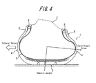
- the land portions of the ground-contact surface 10 of the tread of the vehicle-outer side half portion of the tire, having rigidity thus increased, can reliably support generation of lateral force large enough to resist centrifugal force when these land portions are situated on the outer side in a cornering situation of a vehicle, as shown in FIG. 4 .
- an outer end 7c in the tire radial direction of the turn-up portion 7b of the carcass 7 is disposed in each of the vehicle-outer side half portion and the vehicle-inner side half portion of the tire at a height in the tire radial direction of at least 40% of the tire cross sectional height SH of the tire.
- the external end 7c in the tire radial direction of the turn-up portion 7b of the carcass 7 of at least one (preferably both) of the side half portion and the vehicle-inner side half portion of the tire is positioned, in the tire radial direction, between the maximum width position 13a, 13b and the outermost end in the tire widthwise direction of the inner most belt layer 8a (inclusive of the maximum width position and exclusive of the position corresponding to the outermost end in the widthwise direction of the innermost belt layer 8a) in the tire 1 of the present invention.
- rigidities of the tire side portions in the vicinity of the tread portion 3 are enhanced, thereby further improving stability and controllability of the tire, while suppressing increase in tire weight.
- the position in the tire radial direction of the outermost end in the tire widthwise direction of the innermost belt layer was 90% of the tire cross sectional height SH, the negative ratio in the vehicle-inner side half portion of the ground-contact surface of the tread was 30%, and the negative ratio in the vehicle-outer side half portion of the ground-contact surface was 35% for each of the Example tires and the Comparative Example tires.
- a ground-contact surface of the tread of the half portion, on the vehicle inner side with respect to the tire equatorial plane, of the tire when the tire was mounted on the vehicle was provided with two circumferential main grooves; a ground-contact surface of the tread of the half portion, on the vehicle outer side with respect to the tire equatorial plane, of the tire when the tire was mounted on the vehicle was provided with one circumferential main groove; the average width of a land portion row demarcated between the one circumferential main groove of the vehicle-outer side half portion and one of the two circumferential main grooves (that adjacent to the one circumferential main groove) of the vehicle-inner side half portion, of the ground-contact surface, was set to be 40 mm; and the average width of a land portion row demarcated between the two circumferential main grooves of the vehicle-inner side half portion of the ground-contact surface was 20 mm.
- the side half portion and the vehicle-inner side half portion of the ground-contact surface of the tread shared basically the same dimensions and relationships therebetween, except that those described above including H in/ H out and R in/ R out
- rolling resistance is determined by: assembling a tire with an application rim (6.5J) prescribed in JATMA; inflating the tire at air pressure of 210 KPa; running the tire at 80 km/hour on an indoor drum tester with load (5.42 kN) equivalent to 73% of the maximum loading capacity prescribed in JATMA exerted thereon; and measuring resistance in the tire travelling direction generated at a ground-contact surface.
- Stability and controllability of an actual car is determined by: assembling a tire with a vehicle-designated rim (7.0J); inflating the tire at the vehicle-designated air pressure (250 KPa) and mounting the tire on a passenger car; running the car on an outdoor test course at speed generally expected of a passenger car (60 km/hour to 120 k/hour) under a loading condition of two passengers (3.38 kN to 4.95 kN); and evaluating stability and controllability of the car by feelings.
- the results of "rolling resistance” and "stability and controllability" in Table 1 are expressed as index values, respectively, relative to the results of Comparative Example 1 tire as the control each expressed as 100. The larger index value represents the better performance.
- Example tires have unanimously achieved effective reduction of rolling resistance, with successfully ensuring good stability and controllability.
Abstract
Description
- The present invention relates to a pneumatic radial tire, in particular, a pneumatic radial tire suitable for a passenger car. The present invention especially proposes a technique for effectively reducing rolling resistance of a pneumatic radial tire, while ensuring good stability and controllability thereof.
- Conventional techniques for reducing rolling resistance of a tire include those disclosed in Patent Literature 1,
Patent Literature 2 and the like. - The invention disclosed in Patent Literature 1, which aims at providing a pneumatic tire capable of reducing rolling resistance without sacrificing stability, controllability and riding comfort, is characterized in that: a fold-back end of a carcass is positioned at the height of ≤ 0.15 time the height of the tire section; and a short fiber reinforced layer of ≥ 0.3mm and ≤ 1.0mm in thickness is arranged on the outer surface of the carcass in a sidewall area between a belt end and the fold-back end of the carcass. The short fiber reinforced layer is constituted of: a rubber component obtained by blending 30-60 parts by weight of natural rubber and/or isoprene rubber with 40-70 parts by weight of butadiene rubber; short fiber; and carbon black. At least 90% of the short fiber is oriented at an angle in the range of ±20° relative to the circumferential direction of the tire and the ratio of the complex elasticity E*a in the direction of orientation of the short fiber, with respect to the complex elasticity E*b in the direction orthogonal to the direction of orientation, is ≥ 5.
- Further, the invention disclosed in
Patent Literature 2, which aims at providing a pneumatic tire capable of making weight reduction and good stability and controllability thereof compatible without reducing riding comfort, characterized in that: a carcass layer is made to be a single layer structure; ends of the carcass layer are each folded around a bead core from the inside toward the outside of the tire to interpose a bead filler therein, to a position which exceeds a tire maximum width and does not reach a belt layer; and the height of the bead filler measured from a bead heel is 15-30% of a tire cross section height, the rubber thickness of a sidewall portion is 3.5-5.0 mm, an inner liner is formed of a thermoplastic elastomer composition having Young's modulus of 5-50 MPa and thickness of 0.05-0.25 mm, and the sidewall portion is made of a rubber composition containing at least 70 wt. % of natural rubber. -
- PTL 1:
JP-A 08-175119 - PTL 2:
JP-A 2009-001228 - However, the invention disclosed in Patent Literature 1, which decreases rolling resistance of a tire by reducing tire weight by reducing a dimension in the tire radial direction of a bead filler to suppress eccentricity of the tire, tends to experience deterioration of stability and controllability due to decrease in rigidity of sidewall portions of the tire and there arises a problem that this deterioration of stability and controllability cannot be addressed even by providing an additional reinforcing layers at the sidewall portions.
- Similarly, the invention disclosed in
Patent Literature 2, although it can realize reduction of tire weight by reducing size of a bead filler, i.e. a shorter bead filler, experiences decrease in rigidity of side portions of the tire and therefore there arises a problem that stability and controllability inevitably deteriorate in spite of efforts of enhancing rigidity of the side portions by increasing rubber thickness of the sidewall portions and forming an inner liner by a thermoplastic resin or a thermoplastic elastomer composition having higher Young's modulus and lower specific gravity than rubber. - More specifically, rolling resistance of a standard pneumatic radial tire for a passenger car, where height in the tire radial direction of a bead filler is at least 25 mm and thickness of sidewall rubber is at least 2.5 mm, can be effectively reduced by decreasing the height in the tire radial direction of the bead filer to 10 mm to 20 mm and the thickness of the sidewall rubber to 1 mm to < 2.5 mm (such size reduction, in combination with resulting decrease in eccentricity of the tire, effectively reduces rolling resistance). However, rigidity of side portions of the tire inevitably deteriorates by this modification and it is very difficult to reliably obtain required stability and controllability in such a case even by increasing thickness of sidewall rubber and the like.
- The present invention aims at solving such problems as described above of the prior art and an object thereof is to effectively reduce rolling resistance, while ensuring good stability and controllability of a pneumatic radial tire.
- When a tire assembled with an application rim, inflated at a predetermined air pressure and mounted on a vehicle in a negative camber state is run straight under a predetermined load exerted thereon, a ground-contact length in the tire circumferential direction of a ground-contact surface portion situated on the vehicle inner side when the tire is mounted on the vehicle, of a tread of the tire, is relatively long, while a ground-contact length in the tire circumferential direction of a ground-contact surface portion situated on the vehicle outer side when the tire is mounted on the vehicle, of the tread, tends to be extremely short, such that an outline of a foot print takes on a substantially blunt triangle-like shape as shown in
FIG. 3A . The present invention, being aware of this phenomenon, attempts to increase a ground-contact length in the tire circumferential direction of a ground-contact surface portion situated on the vehicle outer side when the tire is mounted on the vehicle, of the tread of the tire, to be equal to a ground-contact length in the tire circumferential direction of a ground-contact surface portion situated on the vehicle inner side when the tire is mounted on the vehicle, of the tread, during rotation of the tire under a load exerted thereon, such that a relatively large ground-contact area is ensured and the tire exhibits good stability and controllability in both straight running and cornering even when the weight of the tire has been reduced. A pneumatic radial tire of the present invention is characterized in that: - in a cross sectional view in the tire widthwise direction thereof in a state where the tire is assembled with an application rim, inflated at a predetermined air pressure and mounted on a vehicle under a predetermined load exerted thereon, provided that: Lout represents an imaginary line, passing through the maximum width position remotest from the tire equatorial plane in a tire side portion situated on the vehicle outer side, to extend to be orthogonal to the tire equatorial plane; Lin represents an imaginary line, passing through the maximum width position remotest from the tire equatorial plane in a tire side portion situated on the vehicle inner side, to extend to be orthogonal to the tire equatorial plane; Hout represents a distance in the tire radial direction between the imaginary line Lout and a ground-contact end on the vehicle outer side of the tread; and Hin represents a distance in the tire radial direction between the imaginary line Lin and a ground-contact end on the vehicle inner side of the tread, Hout < Hin;
- radius of curvature (Rout) of an outer surface of the tire side portion on the vehicle outer side, at the maximum width position thereof, is smaller than radius of curvature (Rin) of an outer surface of the tire side portion on the vehicle inner side, at the maximum width position thereof;
- a negative ratio, i.e. a groove area ratio, of a ground-contact surface of the tread of a half portion, on the vehicle outer side with respect to the tire equatorial plane, of the tire when the tire is mounted on the vehicle is smaller than a negative ratio of a ground-contact surface of the tread of a half portion, on the vehicle inner side with respect to the tire equatorial plane, of the tire when the tire is mounted on the vehicle; and
- an outer end in the tire radial direction of a turn-up portion around a bead core, of a carcass constituted of at least of one carcass ply, is disposed in each of the half portions of the tire at a height in the tire radial direction of at least 40% of the tire cross sectional height under no load exerted on the tire.
- In the present invention, an "application rim" represents a rim prescribed by the following standard in accordance with a vehicle on which the tire is mounted, "predetermined air pressure" represents air pressure corresponding to the maximum loading capacity in an application tire size prescribed in the standard, and a "predetermined load" represents a load corresponding to the maximum loading capacity in an application tire size prescribed in the standard.
- The "standard" represents an industrial standard which is valid in a region where a tire is manufactured or used. Examples of the standard include "YEAR BOOK" of the Tire and Rim Association Inc. in the United States, "STANDARDS MANUAL" of the European Tyre and Rim Technical Organisation in Europe, and "JATMA YEAR BOOK" of Japan Automobile Tyre Manufacturers Association in Japan.
- Further, "the maximum width position" of a tire side portion represents a position at an outer surface, remotest from the tire equatorial plane, of each tire side portion of a tire inflated at the predetermined air pressure and right under a predetermined load exerted thereon in the present invention.
- Yet further, "the tire cross sectional height" represents a height in the tire radial direction measured from the rim baseline to the outer diameter of the tire.
- In the tire of the present invention as described above, the aforementioned distance Hin in the tire radial direction between the imaginary line Lin and a ground-contact end on the vehicle inner side of the tread is preferably set to be 1.1 to 1.3 times as large as the aforementioned distance Hout in the tire radial direction between the imaginary line Lout and a ground-contact end on the vehicle outer side of the tread.
- Further, it is preferable in the present invention that: the ground-contact surface of the tread of the half portion, on the vehicle inner side with respect to the tire equatorial plane, of the tire when the tire is mounted on the vehicle is provided with two circumferential main grooves; the ground-contact surface of the tread of the half portion, on the vehicle outer side with respect to the tire equatorial plane, of the tire when the tire is mounted on the vehicle is provided with one circumferential main groove; and the average width of a land portion row demarcated between the one circumferential main groove of the ground-contact surface of the vehicle-outer side half portion of the tire and one of the two circumferential main grooves, which is adjacent to the one circumferential main groove, of the ground-contact surface of the vehicle-inner side half portion of the tire is set to be at least 1.5 times as wide as the average width of a land portion row demarcated between the two circumferential main grooves of the ground-contact surface of the vehicle-inner side half portion of the tire.
A width of the land portion row is specified as the average width in the present invention because, even when the circumferential main grooves share the same groove widths and groove depths, at least one of these circumferential main grooves can extend in a zigzag or winding configuration such that the width of the land portion row varies in the circumferential direction. - Yet further, dimension in the tire radial direction of a bead filler, provided on the outer peripheral side of each bead core and between a carcass main body extending in a toroidal shape across the bead cores and the aforementioned turn-up portion of the carcass, is preferably set to be in the range of 10 mm to 20 mm.
- Yet further, it is preferable that: the tire further includes at least one belt layer formed by belt cords and provided on the outer peripheral side of a crown region of the carcass; and an external end in the tire radial direction of the turn-up portion of the carcass of at least one of the vehicle-outer side half portion and the vehicle-inner side half portion of the tire is positioned, in the tire radial direction, between the maximum width position remotest from the tire equatorial plane and the outermost end in the tire widthwise direction of the belt layer in the tire side portions (inclusive of the maximum width position and exclusive of the position corresponding to the outermost end in the widthwise direction of the belt layer).
- According to the pneumatic radial tire of the present invention, radius of curvature of the tire side portion on the vehicle outer side when the tire is mounted on a vehicle, at the maximum width position thereof, is smaller than radius of curvature of the tire side portion on the vehicle inner side when tire is mounted on a vehicle, at the maximum width position thereof. As a result, when load is exerted on the tire, the tire side portion on the vehicle outer side having smaller radius of curvature right under the load is more deformed by larger expansion toward the outer side in the tire widthwise direction, whereby a ground-contact length in the tire circumferential direction of a ground-contact end on the vehicle outer side, of the tread, is elongated to a length substantially equal to a ground-contact length in the tire circumferential direction of a ground-contact end on the vehicle inner side of the tread during straight running of a vehicle and therefore an outline of a foot print takes on a substantially rectangular configuration. That is, it is possible to ensure a relatively large ground-contact area so that the tire exhibits good stability and controllability in both straight running and cornering.
- Further, according to the pneumatic radial tire of the present invention, the aforementioned distance Hout in the tire radial direction on the vehicle outer side is set to be smaller than the aforementioned distance Hin in the tire radial direction on the vehicle inner side, thereby increasing asymmetry in a cross sectional configuration of the tire. As a result, difference in ground-contact length of a ground-contact surface of the tread between the vehicle-inner side half portion and the vehicle-outer side half portion of the tire can be further lessened.
- Yet further, according to the pneumatic radial tire of the present invention, a negative ratio of a ground-contact surface of the tread of the vehicle-outer side half portion of the tire is set to be smaller than a negative ratio of a ground-contact surface of the tread of the vehicle-inner side half portion of the tire. As a result, the ground-contact surface of the tread of the vehicle-inner side half portion of the tire can exhibit good drainage performance, and the ground-contact surface of the tread of the vehicle-outer side half portion of the tire can have relatively high rigidity of land portions to ensure generation of relatively large lateral force in a cornering situation of a vehicle and thus good cornering performance of the vehicle.
- Yet further, according to the pneumatic radial tire of the present invention, an outer end in the tire radial direction of a turn-up portion of the carcass is disposed in each of the vehicle-outer side half portion and the vehicle-inner side half portion of the tire at a height in the tire radial direction of at least 40%, preferably at least 45%, of the tire cross sectional height. As a result, in a case where weight and rolling resistance of a tire are reduced by decreasing volume of bead fillers, deterioration of rigidities of the tire side portions can be effectively prevented from occurring by the sufficiently large turn-up portions of the carcass, thereby effectively eliminating concern about deterioration of stability and controllability of the tire.
- Yet further, according to the pneumatic radial tire of the present invention, the tire may further include at least one belt layer formed by belt cords and provided on the outer peripheral side of a crown region of the carcass; and the external end in the tire radial direction of the turn-up portion of the carcass of at least one (preferably both) of the vehicle-outer side half portion and the vehicle-inner side half portion of the tire may be positioned, in the tire radial direction, between the maximum width position remotest from the tire equatorial plane and the outermost end in the tire widthwise direction of the belt layer in the tire side portions (inclusive of the maximum width position and exclusive of the position corresponding to the outermost end in the widthwise direction of the belt layer). In this case, it is possible to further improve stability and controllability, while effectively curbing rolling resistance.
More specifically, when the outer end of the turn-up portion of the carcass is disposed on the outer side in the tire radial direction of the outermost end in the tire widthwise direction of the belt layer, the tire weight increases to possibly increase rolling resistance of the tire, as well. When the outer end of the turn-up portion of the carcass is disposed on the inner side in the tire radial direction of the maximum width position remotest from the tire equatorial plane of the tire side portion, rigidity of the side portion in the vicinity of the tread decreases to possibly deteriorate stability and controllability of the tire. - In the tire of the present invention, ground-contact properties of the tire mounted on a vehicle can be optimized by setting the aforementioned vehicle-inner side distance Hin in the tire radial direction to be 1.1 to 1.3 times as large as the aforementioned vehicle-outer side distance Hout in the tire radial direction.
More specifically, when the ratio Hin/Hout is less than 1.1, difference in rigidity of the tire side portions is small between the vehicle-inner side and the vehicle-outer side, whereby a ground-contact length on the vehicle outer side of a ground-contact surface of the tread is not sufficiently elongated as anticipated or required. When the ratio Hin/Hout exceeds 1.3, a ground-contact length on the vehicle outer side of a ground-contact surface of the tread is elongated too much, whereby an outline of a foot print then takes on a blunt triangle-like shape which is a mirror-image of the triangle shown inFIG. 3A to disturb the balance of the vehicle. - Further, in the tire of the present invention, it is possible to easily realize required negative ratios in ground-contact surfaces of the tread of the respective tire half portions to make the tire exhibit required drainage and cornering performances by providing a ground-contact surface of the tread of a half portion, on the vehicle inner side with respect to the tire equatorial plane, of the tire when the tire is mounted on the vehicle with two circumferential main grooves; and providing a ground-contact surface of the tread of a half portion, on the vehicle outer side with respect to the tire equatorial plane, of the tire when the tire is mounted on the vehicle with one circumferential main groove.
Yet further, it is possible to further increase lateral force generated in a cornering situation of a vehicle and thus make the vehicle exhibit good cornering performance by setting the average width of a land portion row demarcated between the one circumferential main groove of the vehicle-outer side half portion and one of the two circumferential main grooves (that adjacent to the one circumferential main groove) of the vehicle-inner side half portion of the tire to be at least 1.5 times as wide as the average width of a land portion row demarcated between the two circumferential main grooves of the vehicle-inner side half portion of the tire. - Yet further, in the tire of the present invention, it is possible to decrease volume of a bead filler, i.e. the tire weight as a whole, and thus effectively suppress rolling resistance by setting dimension in the tire radial direction of a bead filler, provided on the outer peripheral side of each bead core and between a carcass main body extending in a toroidal shape across the bead cores and the aforementioned turn-up portion of the carcass, to be in the range of 10 mm to 20 mm.
In this case, decrease in rigidities of the tire side portions and deterioration of stability and controllability of the tire, due to decrease in volume of the bead fillers, can be well compensated by disposing an outer end in the tire radial direction of a turn-up portion of the carcass in each of the side half portion and the vehicle-inner side half portion of the tire at a height in the tire radial direction of at least 40% of the tire cross sectional height, as described above. -
-
FIG. 1 is a cross sectional view in the tire widthwise direction of a tire according to one embodiment of the present invention, in a state in which the tire has been assembled with an application rim, inflated at predetermined air pressure and mounted on a vehicle with predetermined load exerted thereon. -
FIG. 2 is a developed partial plan view of a tread pattern as an example of a ground-contact surface of a tread having circumferential main grooves formed therein. -
FIG. 3A is a diagram showing an example of an outline of a foot print observed in a conventional tire during straight running of a vehicle. -
FIG. 3B is a diagram showing how the outline of a foot print shown inFIG. 3A is improved in the present invention. -
FIG. 4 is a cross sectional view in the widthwise direction of a tire having the tread pattern ofFIG. 2 , exemplarily showing how lateral force is generated in a cornering situation of a vehicle. - An embodiment of the present invention will be described hereinafter with reference to the drawings.
InFIG. 1 , reference number 1 represents an example of a pneumatic radial tire for a passenger car according to the present invention andreference number 2 represents an application rim having the tire 1 assembled therewith. - The pneumatic radial tire 1 inflated at predetermined air pressure and mounted on a vehicle with predetermined load exerted thereon is shown in
FIG. 1 . Reference number 3 represents a tread portion, 4 represents each sidewall portion extending on the inner side in the tire radial direction to be continuous with each side part of thetread portion 3, and 5 represents each bead portion provided to be continuous with an inner end in the tire radial direction of eachsidewall portion 4 inFIG. 1 . - A
main body 7a of a radial carcass 7 constituted of at least one carcass ply (a single carcass ply in the example shown inFIG. 1 ) is provided across a pair ofbead cores 6 embedded inrespective bead portions 5 to extend in a toroidal shape. Respective side end portions of the radial carcass 7 are wound up around therespective bead cores 6 from the inner side toward the outer side in the tire widthwise direction, to constitute respective turn-upportions 7b. - A
belt 8, including, e.g. twobelt layers belt layer 8a intersect belt cords of thebelt layer 8b with respect to the circumferential direction of the tread and abelt reinforcing layer 8c where belt cords extend in the circumferential direction of the tread to completely cover therespective belt layers bead filler 9 is provided between themain body 7a and the turn-upportion 7b of the radial carcass 7 to be adjacent to the outer peripheral surface of eachbead core 6 such that thebead filler 9 decreases thickness thereof from the position adjacent to thebead core 6 toward the outer side in the tire radial direction. - Plural circumferential (and annular)
main grooves 11 continuously extending in the tread circumferential direction in a configuration as desired (such as linear, zigzag) are formed in a ground-contact surface 10 of the tread of the pneumatic radial tire 1 having such an internal reinforcing structure as described above.
A lateral groove or a slant groove (not shown) extending in the tread widthwise direction to intersect the circumferentialmain groove 11 may be formed in the ground-contact surface 10. - When the tire 1 shown in
FIG. 1 is mounted on a vehicle, a half portion on the right-hand side with respect to the tire equatorial plane E of the tire 1 in the drawing is to be situated on the outer side of the vehicle and a half portion on the left-hand side with respect to the tire equatorial plane E of the tire 1 in the drawing is to be situated on the inner side of the vehicle. - In the tire of the present invention, in a cross sectional view in the tire widthwise direction thereof as shown in
FIG. 1 , provided that: animaginary line 14a, passing through themaximum width position 13a remotest from the tire equatorial plane E in atire side portion 12a situated on the vehicle outer side, extends to be orthogonal to the tire equatorial plane E; animaginary line 14b, passing through themaximum width position 13b remotest from the tire equatorial plane E in atire side portion 12b situated on the vehicle inner side, extends to be orthogonal to the tire equatorial plane E; Hout represents a distance in the tire radial direction between theimaginary line 14a and a ground-contact end 15a on the vehicle outer side of the tread; and Hin represents a distance in the tire radial direction between theimaginary line 14b and a ground-contact end 15b on the vehicle inner side of the tread, Hout < Hin. It is preferable to set the distance Hin in the tire radial direction to be 1.1 to 1.3 times as large as the distance Hout in the tire radial direction. - Further, in the tire of the present invention, radius of curvature Rout of an outer surface of the
tire side portion 12a on the vehicle outer side, at themaximum width position 13a thereof, is set to be smaller than radius of curvature Rin of an outer surface of thetire side portion 12b on the vehicle inner side, at themaximum width position 13b thereof. It is preferable to set the radius of curvature Rin to be 1.1 to 1.3 times as large as the radius of curvature Rout. - Yet further, a negative ratio, i.e. a groove area ratio, of the ground-
contact surface 10 of the tread of the half portion, on the vehicle outer side, of the tire when the tire is mounted on the vehicle is smaller than a negative ratio of the ground-contact surface 10 of the tread of the half portion, on the vehicle inner side, of the tire when the tire is mounted on the vehicle. It is preferable to set the negative ratio in the vehicle-inner side half portion to be 1.5 to 2.0 times as large as the negative ratio in the vehicle-outer side half portion. - Yet further, an
outer end 7c in the tire radial direction of a turn-upportion 7b, wound around thebead core 6, of the carcass 7 is disposed in each of the vehicle-outer side half portion and the vehicle-inner side half portion of the tire at a height in the tire radial direction of at least 40%, preferably at least 45%, of the tire cross sectional height SH of the tire inflated at predetermined internal pressure with no load exerted thereon. - Yet further, in the tire 1 of the present invention structured as described above, the
external end 7c of the turn-upportion 7b of the carcass 7 of at least one (preferably both) of the side half portion and the vehicle-inner side half portion of the tire is preferably positioned, in the tire radial direction, between themaximum width position most belt layer 8a in thetire side portions innermost belt layer 8a). - Yet further, plural circumferential (and annular)
main grooves 11 extending in the tread circumferential direction in a configuration as desired such as linear, zigzag shape (two linear circumferentialmain grooves 11 inFIG. 2 ) are formed in the tread 3 such that thesemain grooves 11 are located in a half portion on the vehicle-inner side with respect to the tire equatorial plane e, of the ground-contact surface 10 of the tread of the tire 1, when the tire 1 is mounted on a vehicle; and another one circumferential (and annular)main groove 11, which extends in a configuration as desired and may have the same groove width and groove depth as those of the aforementioned two circumferentialmain grooves 11, is formed in the tread 3 such that the onemain groove 11 is located in a half portion on the vehicle-outer side with respect to the tire equatorial plane e, of the ground-contact surface 10 of the tread of the tire 1, when the tire 1 is mounted on a vehicle, as exemplarily shown in a developed view of a tread pattern ofFIG. 2 .
The negative ratio in the vehicle-inner side half portion of the ground-contact surface 10 of the tread and the negative ratio in the vehicle-outer side half portion of the ground-contact surface 10 are set as described above, respectively.
The average width w1 of aland portion row 16 demarcated between the one circumferentialmain groove 11 of the vehicle-outer side half portion and one of the two circumferential main grooves 11 (that adjacent to the one circumferential main groove) of the vehicle-inner side half portion, of the ground-contact surface 10, is set to be at least 1.5 times, preferably at least 2.0 times, as wide as the average width w2 of aland portion row 17 demarcated between the two circumferentialmain grooves 11 of the vehicle-inner side half portion of the ground-contact surface 10, so that land portions of the side half portion of the ground-contact surface 10 is imparted with rigidity as required.
Aland portion row 18 demarcated between the one circumferentialmain groove 11 in the side half portion and the ground-contact end 15a on the outer side in the tire widthwise direction, of the ground-contact surface 10, and aland portion row 19 demarcated between one of the two circumferentialmain grooves 11 in the vehicle-inner side half portion and the ground-contact end 15b on the inner side in the tire widthwise direction, of the ground-contact surface 10, may have widths equivalent to 25% to 30% of the ground-contact width W of the tread, respectively.
Phantom line inFIG. 2 represents an example of outline of a foot print. - Further, dimension in the tire radial direction of the
bead filler 9, provided on the outer peripheral side of eachbead core 6 and between the carcassmain body 7a and the turn-upportion 7b of the carcass 7 as shown inFIG. 1 , is preferably set to be in the range of 10 mm to 20 mm, preferably in the range of 10 mm to 15 mm, so that tire weight is reliably reduced to ensure decrease in rolling resistance of the tire. - According to the tier 1 structured as described above, radius of curvature Rout of the
tire side portion 12a on the vehicle outer side when the tire is mounted on a vehicle, at themaximum width position 13a thereof, is made smaller than radius of curvature Rin of thetire side portion 12b on the vehicle inner side when tire is mounted on the vehicle, at themaximum width position 13b thereof, so that thetire side portion 12a on the vehicle outer side is sufficiently deformed by expanding toward the outer side in the tire widthwise direction when load is exerted on the tire. As a result, an outline of a foot print of the tire during straight running of a vehicle, which takes on a substantially blunt triangle-like shape as shown inFIG. 3A in the conventional tire having a symmetrical cross sectional configuration in the tire widthwise direction with respect to the tire equatorial plane e, can be improved to a substantially rectangular shape as shown inFIG. 3B , so that a ground-contact length in the tread circumferential direction of a ground-contact surface on the side of the tread can be sufficiently elongated. That is, according to the tire 1 of the present invention, it is possible to reduce tire weight and make the tire demonstrate good stability and controllability in straight running and cornering, respectively, due to high road-surface-gripping force achieved under a large ground-contact area. - Yet further, the aforementioned distance Hout in the tire radial direction on the vehicle outer side is set to be smaller than the aforementioned distance Hin in the tire radial direction on the vehicle inner side in the tire 1 of the present invention, thereby changing rigidities of the
tire side portions - Yet further, a negative ratio of a ground-
contact surface 10 of the tread of the vehicle-outer side half portion of the tire is set to be smaller than a negative ratio of a ground-contact surface of the tread of the vehicle-inner side half portion of the tire in the tire 1 of the present invention, so that rigidity of land portions of the ground-contact surface 10 of the tread of the side half portion of the tire increases. The land portions of the ground-contact surface 10 of the tread of the vehicle-outer side half portion of the tire, having rigidity thus increased, can reliably support generation of lateral force large enough to resist centrifugal force when these land portions are situated on the outer side in a cornering situation of a vehicle, as shown inFIG. 4 . - Yet further, in the tire 1 of the present invention, an
outer end 7c in the tire radial direction of the turn-upportion 7b of the carcass 7 is disposed in each of the vehicle-outer side half portion and the vehicle-inner side half portion of the tire at a height in the tire radial direction of at least 40% of the tire cross sectional height SH of the tire. As a result, decrease in rigidities of the tire side portions caused by decrease in weight of the tire can be compensated by the turn-upportions 7b to sufficiently eliminate concern about deterioration of stability and controllability of the tire. - Yet further, the
external end 7c in the tire radial direction of the turn-upportion 7b of the carcass 7 of at least one (preferably both) of the side half portion and the vehicle-inner side half portion of the tire is positioned, in the tire radial direction, between themaximum width position most belt layer 8a (inclusive of the maximum width position and exclusive of the position corresponding to the outermost end in the widthwise direction of theinnermost belt layer 8a) in the tire 1 of the present invention. As a result, rigidities of the tire side portions in the vicinity of the tread portion 3 are enhanced, thereby further improving stability and controllability of the tire, while suppressing increase in tire weight. - Actual car tests for evaluating "rolling resistance" and "stability and controllability" were carried out for each of Example tires and Comparative Example tires having size: 215/60 R16. Measurement results shown in Table 1 are expressed as index values relative to the results of Comparative Example 1 tire as the control each expressed as 100.
The larger index value represents the better result. - The respective Example tires have: ratio (ht/SH) of the height ht of the outer end of the turn-up portion of the radial carcass with respect to the cross sectional height SH of the tire, ratio Hin/Hout, and dimension in the tire radial direction of the bead filler as shown in Table 1; Rin = 80 mm and Rout = 60 mm (Rin/Rout = 1.33); and ht/SH in the range of 40% to 90%.
The respective Comparative Example tires have: ratio ht/SH and ratio Hin/Hout as shown in Table 1; and dimension in the tire radial direction of the bead filler = 15 mm, Rin = Rout = 70 mm (Rin/Rout = 1.0).
The position in the tire radial direction of the outermost end in the tire widthwise direction of the innermost belt layer was 90% of the tire cross sectional height SH, the negative ratio in the vehicle-inner side half portion of the ground-contact surface of the tread was 30%, and the negative ratio in the vehicle-outer side half portion of the ground-contact surface was 35% for each of the Example tires and the Comparative Example tires.
Further, a ground-contact surface of the tread of the half portion, on the vehicle inner side with respect to the tire equatorial plane, of the tire when the tire was mounted on the vehicle was provided with two circumferential main grooves; a ground-contact surface of the tread of the half portion, on the vehicle outer side with respect to the tire equatorial plane, of the tire when the tire was mounted on the vehicle was provided with one circumferential main groove; the average width of a land portion row demarcated between the one circumferential main groove of the vehicle-outer side half portion and one of the two circumferential main grooves (that adjacent to the one circumferential main groove) of the vehicle-inner side half portion, of the ground-contact surface, was set to be 40 mm; and the average width of a land portion row demarcated between the two circumferential main grooves of the vehicle-inner side half portion of the ground-contact surface was 20 mm. - For each of the Example tires and the Comparative Example tires, the side half portion and the vehicle-inner side half portion of the ground-contact surface of the tread shared basically the same dimensions and relationships therebetween, except that those described above including Hin/Hout and Rin/Rout
-


- In the present invention, rolling resistance is determined by: assembling a tire with an application rim (6.5J) prescribed in JATMA; inflating the tire at air pressure of 210 KPa; running the tire at 80 km/hour on an indoor drum tester with load (5.42 kN) equivalent to 73% of the maximum loading capacity prescribed in JATMA exerted thereon; and measuring resistance in the tire travelling direction generated at a ground-contact surface.
Stability and controllability of an actual car is determined by: assembling a tire with a vehicle-designated rim (7.0J); inflating the tire at the vehicle-designated air pressure (250 KPa) and mounting the tire on a passenger car; running the car on an outdoor test course at speed generally expected of a passenger car (60 km/hour to 120 k/hour) under a loading condition of two passengers (3.38 kN to 4.95 kN); and evaluating stability and controllability of the car by feelings.
The results of "rolling resistance" and "stability and controllability" in Table 1 are expressed as index values, respectively, relative to the results of Comparative Example 1 tire as the control each expressed as 100. The larger index value represents the better performance. - It is understood from Table 1 that the Example tires have unanimously achieved effective reduction of rolling resistance, with successfully ensuring good stability and controllability.
-
- 1
- Pneumatic radial tire
- 2
- Application rim
- 3
- Tread portion
- 4
- Sidewall portion
- 5
- Bead portion
- 6
- Bead core
- 7
- Radial carcass
- 7a
- Main body of radial carcass
- 7b
- Turn-up portion of radial carcass
- 7c
- Outer end of turn-up portion
- 8
- Belt
- 8a, 8b
- Belt layer
- 8c
- Belt reinforcing layer
- 9
- Bead filler
- 10
- Ground-contact surface of tread
- 11
- Circumferential main groove
- 12a, 12b
- Tire side portion
- 13a, 13b
- Maximum width position
- 14a, 14b
- Imaginary line
- 15a, 15b
- Ground-contact end of tread
- 16-19
- Land portion row
- E
- Tire equatorial plane
- e
- Tire equatorial plane
- Hin, Hout
- Distance in tire radial direction
- Rin, Rout
- Radius of curvature
- w1, w2
- Average width
- W
- Ground-contact surface width of tread
- Ht
- Height of outer end of turn-up portion of radial carcass
- SH
- Tire cross sectional height
Claims (5)
- A pneumatic radial tire, characterized in that:in a cross sectional view in the tire widthwise direction thereof in a state where the tire is assembled with an application rim, inflated at a predetermined air pressure and mounted on a vehicle under a predetermined load exerted thereon, provided that: Lout represents an imaginary line, passing through the maximum width position remotest from the tire equatorial plane in a tire side portion situated on the vehicle outer side, to extend to be orthogonal to the tire equatorial plane; Lin represents an imaginary line, passing through the maximum width position remotest from the tire equatorial plane in a tire side portion situated on the vehicle inner side, to extend to be orthogonal to the tire equatorial plane; Hout represents a distance in the tire radial direction between the imaginary line Lout and a ground-contact end on the vehicle outer side of the tread; and Hin represents a distance in the tire radial direction between the imaginary line Lin and a ground-contact end on the vehicle inner side of the tread, Hout < Hin;radius of curvature (Rout) of the tire side portion on the vehicle outer side, at the maximum width position thereof, is smaller than radius of curvature (Rin) of the tire side portion on the vehicle inner side, at the maximum width position thereof;a negative ratio of a ground-contact surface of the tread of a half portion, on the vehicle outer side with respect to the tire equatorial plane, of the tire when the tire is mounted on the vehicle is smaller than a negative ratio of a ground-contact surface of the tread of a half portion, on the vehicle inner side with respect to the tire equatorial plane, of the tire when the tire is mounted on the vehicle; andan outer end in the tire radial direction of a turn-up portion around a bead core, of a carcass constituted of at least of one carcass ply, is disposed in each of the half portions of the tire at a height in the tire radial direction of at least 40% of the tire cross sectional height under no load exerted on the tire.
- The pneumatic radial tire of claim 1, wherein said distance Hin in the tire radial direction between the imaginary line Rin and a ground-contact end on the vehicle inner side of the tread is set to be 1.1 to 1.3 times as large as said distance Hout in the tire radial direction between the imaginary line Rout and a ground-contact end on the vehicle outer side of the tread.
- The pneumatic radial tire of claim 1 or 2, wherein:the ground-contact surface of the tread of the half portion, on the vehicle inner side with respect to the tire equatorial plane, of the tire when the tire is mounted on the vehicle is provided with two circumferential main grooves;the ground-contact surface of the tread of the half portion, on the vehicle outer side with respect to the tire equatorial plane, of the tire when the tire is mounted on the vehicle is provided with one circumferential main groove; andthe average width of a land portion row demarcated between the one circumferential main groove of the ground-contact surface of the side half portion of the tire and one of the two circumferential main grooves, which is adjacent to the one circumferential main groove, of the ground-contact surface of the vehicle-inner side half portion of the tire is set to be at least 1.5 times as wide as the average width of a land portion row demarcated between the two circumferential main grooves of the ground-contact surface of the vehicle-inner side half portion of the tire.
- The pneumatic radial tire of any of claims 1 to 3, wherein dimension in the tire radial direction of a bead filler, provided on the outer peripheral side of each bead core and between a carcass main body extending in a toroidal shape across the bead cores and the turn-up portion of the carcass, is set to be in the range of 10 mm to 20 mm.
- The pneumatic radial tire of any of claims 1 to 4, wherein:the tire further includes at least one belt layer formed by belt cords and provided on the outer peripheral side of a crown region of the carcass; andan external end in the tire radial direction of the turn-up portion of the carcass of at least one of the vehicle-outer side half portion and the vehicle-inner side half portion of the tire is positioned, in the tire radial direction, between the maximum width position remotest from the tire equatorial plane and the outermost end in the tire widthwise direction of the belt layer in the tire side portions (inclusive of the maximum width position and exclusive of the position corresponding to the outermost end in the widthwise direction of the belt layer).
Applications Claiming Priority (2)
| Application Number | Priority Date | Filing Date | Title |
|---|---|---|---|
| JP2011038826 | 2011-02-24 | ||
| PCT/JP2012/001208 WO2012114743A1 (en) | 2011-02-24 | 2012-02-22 | Pneumatic radial tire |
Publications (3)
| Publication Number | Publication Date |
|---|---|
| EP2679407A1 true EP2679407A1 (en) | 2014-01-01 |
| EP2679407A4 EP2679407A4 (en) | 2016-01-06 |
| EP2679407B1 EP2679407B1 (en) | 2018-04-04 |
Family
ID=46720535
Family Applications (1)
| Application Number | Title | Priority Date | Filing Date |
|---|---|---|---|
| EP12749156.1A Not-in-force EP2679407B1 (en) | 2011-02-24 | 2012-02-22 | Pneumatic radial tire |
Country Status (5)
| Country | Link |
|---|---|
| US (1) | US9487051B2 (en) |
| EP (1) | EP2679407B1 (en) |
| JP (1) | JP5887332B2 (en) |
| CN (1) | CN103391853B (en) |
| WO (1) | WO2012114743A1 (en) |
Families Citing this family (8)
| Publication number | Priority date | Publication date | Assignee | Title |
|---|---|---|---|---|
| EP3074248A4 (en) | 2013-11-27 | 2017-07-12 | Bridgestone Americas Tire Operations, LLC | Tire construction having a continuous body ply turn up structure |
| CN107074024A (en) * | 2014-10-16 | 2017-08-18 | 普利司通美国轮胎运营有限责任公司 | Tire with asymmetric carcass ply Rotating fields |
| JP6704340B2 (en) * | 2016-12-22 | 2020-06-03 | 株式会社ブリヂストン | tire |
| JP6844377B2 (en) * | 2017-03-30 | 2021-03-17 | 住友ゴム工業株式会社 | tire |
| JP6988349B2 (en) * | 2017-10-05 | 2022-01-05 | 住友ゴム工業株式会社 | tire |
| CN111791650B (en) * | 2019-04-03 | 2024-02-20 | 住友橡胶工业株式会社 | Tire with a tire body |
| CN111791651A (en) * | 2019-04-03 | 2020-10-20 | 住友橡胶工业株式会社 | Tyre for vehicle wheels |
| JP7129950B2 (en) * | 2019-06-14 | 2022-09-02 | 株式会社ブリヂストン | pneumatic tire |
Family Cites Families (20)
| Publication number | Priority date | Publication date | Assignee | Title |
|---|---|---|---|---|
| JPH03148305A (en) * | 1989-11-01 | 1991-06-25 | Sumitomo Rubber Ind Ltd | Pneumatic radial tire |
| JPH05201202A (en) * | 1992-01-29 | 1993-08-10 | Bridgestone Corp | Pneumatic tire |
| AU647984B2 (en) * | 1992-01-29 | 1994-03-31 | Bridgestone Corporation | Pneumatic radial tires |
| JP3512843B2 (en) * | 1994-01-21 | 2004-03-31 | 株式会社ブリヂストン | Pneumatic radial tire |
| JP2788715B2 (en) | 1994-12-27 | 1998-08-20 | 住友ゴム工業株式会社 | Pneumatic tire |
| JP3384760B2 (en) * | 1998-12-15 | 2003-03-10 | 住友ゴム工業株式会社 | Tubeless tire |
| US6527025B1 (en) | 1998-09-11 | 2003-03-04 | Sumitomo Rubber Industries, Ltd. | Tubeless tire |
| JP3410676B2 (en) * | 1999-05-06 | 2003-05-26 | 住友ゴム工業株式会社 | Radial tires for heavy loads |
| JP4593769B2 (en) * | 2000-12-26 | 2010-12-08 | 株式会社ブリヂストン | Tire / rim wheel assembly |
| JP4153224B2 (en) | 2001-05-11 | 2008-09-24 | 不二精工株式会社 | Pneumatic tire manufacturing method and pneumatic tire |
| FR2827810A1 (en) * | 2001-07-25 | 2003-01-31 | Michelin Soc Tech | TIRE HAVING DISSYMMETRIC AND REINFORCED SIDES |
| JP2004231057A (en) | 2003-01-30 | 2004-08-19 | Sumitomo Rubber Ind Ltd | Pneumatic tire |
| US7278455B2 (en) * | 2004-12-20 | 2007-10-09 | The Goodyear Tire & Rubber Company | Asymmetrical pneumatic run-flat tire |
| JP4764085B2 (en) | 2005-07-22 | 2011-08-31 | 株式会社ブリヂストン | Pneumatic tire |
| CA2633143A1 (en) * | 2005-12-20 | 2007-06-28 | Pirelli Tyre S.P.A. | Pneumatic tire having an asymmetric tread profile |
| JP4420098B2 (en) | 2006-11-06 | 2010-02-24 | 横浜ゴム株式会社 | Pneumatic tire |
| JP4107392B1 (en) | 2007-06-25 | 2008-06-25 | 横浜ゴム株式会社 | Pneumatic tire |
| CN101959702B (en) * | 2008-02-04 | 2013-06-05 | 株式会社普利司通 | Studless tire |
| JP2010125891A (en) * | 2008-11-25 | 2010-06-10 | Yokohama Rubber Co Ltd:The | Pneumatic tire |
| JP5442278B2 (en) * | 2009-02-27 | 2014-03-12 | 株式会社ブリヂストン | studless tire |
-
2012
- 2012-02-22 EP EP12749156.1A patent/EP2679407B1/en not_active Not-in-force
- 2012-02-22 CN CN201280010391.4A patent/CN103391853B/en not_active Expired - Fee Related
- 2012-02-22 WO PCT/JP2012/001208 patent/WO2012114743A1/en active Application Filing
- 2012-02-22 US US13/984,794 patent/US9487051B2/en active Active
- 2012-02-22 JP JP2013500893A patent/JP5887332B2/en active Active
Also Published As
| Publication number | Publication date |
|---|---|
| EP2679407A4 (en) | 2016-01-06 |
| WO2012114743A1 (en) | 2012-08-30 |
| EP2679407B1 (en) | 2018-04-04 |
| JP5887332B2 (en) | 2016-03-16 |
| CN103391853A (en) | 2013-11-13 |
| JPWO2012114743A1 (en) | 2014-07-07 |
| CN103391853B (en) | 2016-08-10 |
| US9487051B2 (en) | 2016-11-08 |
| US20130312886A1 (en) | 2013-11-28 |
Similar Documents
| Publication | Publication Date | Title |
|---|---|---|
| EP2679407B1 (en) | Pneumatic radial tire | |
| EP2682286B1 (en) | Pneumatic tire | |
| EP3202596B1 (en) | Run-flat tire | |
| US10166817B2 (en) | Pneumatic tire | |
| US20150165822A1 (en) | Pneumatic Tire | |
| EP2743098A2 (en) | Pneumatic tire | |
| WO2010137347A1 (en) | Run-flat tire | |
| JP5993636B2 (en) | Pneumatic tire | |
| JP2013220808A (en) | Pneumatic tire | |
| JP4909035B2 (en) | Pneumatic tire | |
| US20190054777A1 (en) | Pneumatic Tire | |
| JP2008279820A (en) | Pneumatic tire | |
| JP5239566B2 (en) | Pneumatic tire | |
| JP7200680B2 (en) | pneumatic tire | |
| EP3932695A1 (en) | Motorcycle tire | |
| JP6718264B2 (en) | Run flat tires | |
| WO2023105830A1 (en) | Pneumatic radial tire for passenger vehicle | |
| WO2023105828A1 (en) | Pneumatic radial tire for passenger vehicle | |
| EP4360912A1 (en) | Pneumatic radial tire for passenger vehicle | |
| WO2023105829A1 (en) | Pneumatic radial tire for passenger car | |
| WO2023105831A1 (en) | Pneumatic radial tire for passenger car | |
| JP5823795B2 (en) | Heavy duty pneumatic radial tire | |
| EP4353494A1 (en) | Pneumatic radial tire for passenger vehicle | |
| WO2023105827A1 (en) | Pneumatic radial tire for passenger vehicle | |
| JP2011110998A (en) | Pneumatic radial tire for heavy load |
Legal Events
| Date | Code | Title | Description |
|---|---|---|---|
| PUAI | Public reference made under article 153(3) epc to a published international application that has entered the european phase |
Free format text: ORIGINAL CODE: 0009012 |
|
| 17P | Request for examination filed |
Effective date: 20130709 |
|
| AK | Designated contracting states |
Kind code of ref document: A1 Designated state(s): AL AT BE BG CH CY CZ DE DK EE ES FI FR GB GR HR HU IE IS IT LI LT LU LV MC MK MT NL NO PL PT RO RS SE SI SK SM TR |
|
| DAX | Request for extension of the european patent (deleted) | ||
| RA4 | Supplementary search report drawn up and despatched (corrected) |
Effective date: 20151204 |
|
| RIC1 | Information provided on ipc code assigned before grant |
Ipc: B60C 11/03 20060101ALI20151130BHEP Ipc: B60C 3/06 20060101AFI20151130BHEP Ipc: B60C 15/06 20060101ALI20151130BHEP |
|
| REG | Reference to a national code |
Ref country code: DE Ref legal event code: R079 Ref document number: 602012044759 Country of ref document: DE Free format text: PREVIOUS MAIN CLASS: B60C0009080000 Ipc: B60C0003060000 |
|
| RIC1 | Information provided on ipc code assigned before grant |
Ipc: B60C 15/06 20060101ALI20170711BHEP Ipc: B60C 3/06 20060101AFI20170711BHEP Ipc: B60C 11/03 20060101ALI20170711BHEP |
|
| GRAP | Despatch of communication of intention to grant a patent |
Free format text: ORIGINAL CODE: EPIDOSNIGR1 |
|
| STAA | Information on the status of an ep patent application or granted ep patent |
Free format text: STATUS: GRANT OF PATENT IS INTENDED |
|
| INTG | Intention to grant announced |
Effective date: 20170922 |
|
| GRAS | Grant fee paid |
Free format text: ORIGINAL CODE: EPIDOSNIGR3 |
|
| GRAA | (expected) grant |
Free format text: ORIGINAL CODE: 0009210 |
|
| STAA | Information on the status of an ep patent application or granted ep patent |
Free format text: STATUS: THE PATENT HAS BEEN GRANTED |
|
| AK | Designated contracting states |
Kind code of ref document: B1 Designated state(s): AL AT BE BG CH CY CZ DE DK EE ES FI FR GB GR HR HU IE IS IT LI LT LU LV MC MK MT NL NO PL PT RO RS SE SI SK SM TR |
|
| REG | Reference to a national code |
Ref country code: GB Ref legal event code: FG4D |
|
| REG | Reference to a national code |
Ref country code: CH Ref legal event code: EP |
|
| REG | Reference to a national code |
Ref country code: AT Ref legal event code: REF Ref document number: 985194 Country of ref document: AT Kind code of ref document: T Effective date: 20180415 |
|
| REG | Reference to a national code |
Ref country code: DE Ref legal event code: R096 Ref document number: 602012044759 Country of ref document: DE |
|
| REG | Reference to a national code |
Ref country code: IE Ref legal event code: FG4D |
|
| REG | Reference to a national code |
Ref country code: NL Ref legal event code: MP Effective date: 20180404 |
|
| REG | Reference to a national code |
Ref country code: LT Ref legal event code: MG4D |
|
| PG25 | Lapsed in a contracting state [announced via postgrant information from national office to epo] |
Ref country code: NL Free format text: LAPSE BECAUSE OF FAILURE TO SUBMIT A TRANSLATION OF THE DESCRIPTION OR TO PAY THE FEE WITHIN THE PRESCRIBED TIME-LIMIT Effective date: 20180404 |
|
| PG25 | Lapsed in a contracting state [announced via postgrant information from national office to epo] |
Ref country code: SE Free format text: LAPSE BECAUSE OF FAILURE TO SUBMIT A TRANSLATION OF THE DESCRIPTION OR TO PAY THE FEE WITHIN THE PRESCRIBED TIME-LIMIT Effective date: 20180404 Ref country code: PL Free format text: LAPSE BECAUSE OF FAILURE TO SUBMIT A TRANSLATION OF THE DESCRIPTION OR TO PAY THE FEE WITHIN THE PRESCRIBED TIME-LIMIT Effective date: 20180404 Ref country code: LT Free format text: LAPSE BECAUSE OF FAILURE TO SUBMIT A TRANSLATION OF THE DESCRIPTION OR TO PAY THE FEE WITHIN THE PRESCRIBED TIME-LIMIT Effective date: 20180404 Ref country code: ES Free format text: LAPSE BECAUSE OF FAILURE TO SUBMIT A TRANSLATION OF THE DESCRIPTION OR TO PAY THE FEE WITHIN THE PRESCRIBED TIME-LIMIT Effective date: 20180404 Ref country code: BG Free format text: LAPSE BECAUSE OF FAILURE TO SUBMIT A TRANSLATION OF THE DESCRIPTION OR TO PAY THE FEE WITHIN THE PRESCRIBED TIME-LIMIT Effective date: 20180704 Ref country code: NO Free format text: LAPSE BECAUSE OF FAILURE TO SUBMIT A TRANSLATION OF THE DESCRIPTION OR TO PAY THE FEE WITHIN THE PRESCRIBED TIME-LIMIT Effective date: 20180704 Ref country code: FI Free format text: LAPSE BECAUSE OF FAILURE TO SUBMIT A TRANSLATION OF THE DESCRIPTION OR TO PAY THE FEE WITHIN THE PRESCRIBED TIME-LIMIT Effective date: 20180404 Ref country code: AL Free format text: LAPSE BECAUSE OF FAILURE TO SUBMIT A TRANSLATION OF THE DESCRIPTION OR TO PAY THE FEE WITHIN THE PRESCRIBED TIME-LIMIT Effective date: 20180404 |
|
| PG25 | Lapsed in a contracting state [announced via postgrant information from national office to epo] |
Ref country code: GR Free format text: LAPSE BECAUSE OF FAILURE TO SUBMIT A TRANSLATION OF THE DESCRIPTION OR TO PAY THE FEE WITHIN THE PRESCRIBED TIME-LIMIT Effective date: 20180705 Ref country code: RS Free format text: LAPSE BECAUSE OF FAILURE TO SUBMIT A TRANSLATION OF THE DESCRIPTION OR TO PAY THE FEE WITHIN THE PRESCRIBED TIME-LIMIT Effective date: 20180404 Ref country code: LV Free format text: LAPSE BECAUSE OF FAILURE TO SUBMIT A TRANSLATION OF THE DESCRIPTION OR TO PAY THE FEE WITHIN THE PRESCRIBED TIME-LIMIT Effective date: 20180404 Ref country code: HR Free format text: LAPSE BECAUSE OF FAILURE TO SUBMIT A TRANSLATION OF THE DESCRIPTION OR TO PAY THE FEE WITHIN THE PRESCRIBED TIME-LIMIT Effective date: 20180404 |
|
| REG | Reference to a national code |
Ref country code: AT Ref legal event code: MK05 Ref document number: 985194 Country of ref document: AT Kind code of ref document: T Effective date: 20180404 |
|
| PG25 | Lapsed in a contracting state [announced via postgrant information from national office to epo] |
Ref country code: PT Free format text: LAPSE BECAUSE OF FAILURE TO SUBMIT A TRANSLATION OF THE DESCRIPTION OR TO PAY THE FEE WITHIN THE PRESCRIBED TIME-LIMIT Effective date: 20180806 |
|
| REG | Reference to a national code |
Ref country code: DE Ref legal event code: R097 Ref document number: 602012044759 Country of ref document: DE |
|
| PG25 | Lapsed in a contracting state [announced via postgrant information from national office to epo] |
Ref country code: SK Free format text: LAPSE BECAUSE OF FAILURE TO SUBMIT A TRANSLATION OF THE DESCRIPTION OR TO PAY THE FEE WITHIN THE PRESCRIBED TIME-LIMIT Effective date: 20180404 Ref country code: AT Free format text: LAPSE BECAUSE OF FAILURE TO SUBMIT A TRANSLATION OF THE DESCRIPTION OR TO PAY THE FEE WITHIN THE PRESCRIBED TIME-LIMIT Effective date: 20180404 Ref country code: DK Free format text: LAPSE BECAUSE OF FAILURE TO SUBMIT A TRANSLATION OF THE DESCRIPTION OR TO PAY THE FEE WITHIN THE PRESCRIBED TIME-LIMIT Effective date: 20180404 Ref country code: CZ Free format text: LAPSE BECAUSE OF FAILURE TO SUBMIT A TRANSLATION OF THE DESCRIPTION OR TO PAY THE FEE WITHIN THE PRESCRIBED TIME-LIMIT Effective date: 20180404 Ref country code: RO Free format text: LAPSE BECAUSE OF FAILURE TO SUBMIT A TRANSLATION OF THE DESCRIPTION OR TO PAY THE FEE WITHIN THE PRESCRIBED TIME-LIMIT Effective date: 20180404 Ref country code: EE Free format text: LAPSE BECAUSE OF FAILURE TO SUBMIT A TRANSLATION OF THE DESCRIPTION OR TO PAY THE FEE WITHIN THE PRESCRIBED TIME-LIMIT Effective date: 20180404 |
|
| PLBE | No opposition filed within time limit |
Free format text: ORIGINAL CODE: 0009261 |
|
| STAA | Information on the status of an ep patent application or granted ep patent |
Free format text: STATUS: NO OPPOSITION FILED WITHIN TIME LIMIT |
|
| PG25 | Lapsed in a contracting state [announced via postgrant information from national office to epo] |
Ref country code: SM Free format text: LAPSE BECAUSE OF FAILURE TO SUBMIT A TRANSLATION OF THE DESCRIPTION OR TO PAY THE FEE WITHIN THE PRESCRIBED TIME-LIMIT Effective date: 20180404 Ref country code: IT Free format text: LAPSE BECAUSE OF FAILURE TO SUBMIT A TRANSLATION OF THE DESCRIPTION OR TO PAY THE FEE WITHIN THE PRESCRIBED TIME-LIMIT Effective date: 20180404 |
|
| 26N | No opposition filed |
Effective date: 20190107 |
|
| PG25 | Lapsed in a contracting state [announced via postgrant information from national office to epo] |
Ref country code: SI Free format text: LAPSE BECAUSE OF FAILURE TO SUBMIT A TRANSLATION OF THE DESCRIPTION OR TO PAY THE FEE WITHIN THE PRESCRIBED TIME-LIMIT Effective date: 20180404 |
|
| REG | Reference to a national code |
Ref country code: CH Ref legal event code: PL |
|
| GBPC | Gb: european patent ceased through non-payment of renewal fee |
Effective date: 20190222 |
|
| PG25 | Lapsed in a contracting state [announced via postgrant information from national office to epo] |
Ref country code: MC Free format text: LAPSE BECAUSE OF FAILURE TO SUBMIT A TRANSLATION OF THE DESCRIPTION OR TO PAY THE FEE WITHIN THE PRESCRIBED TIME-LIMIT Effective date: 20180404 Ref country code: LU Free format text: LAPSE BECAUSE OF NON-PAYMENT OF DUE FEES Effective date: 20190222 |
|
| REG | Reference to a national code |
Ref country code: BE Ref legal event code: MM Effective date: 20190228 |
|
| REG | Reference to a national code |
Ref country code: IE Ref legal event code: MM4A |
|
| PG25 | Lapsed in a contracting state [announced via postgrant information from national office to epo] |
Ref country code: LI Free format text: LAPSE BECAUSE OF NON-PAYMENT OF DUE FEES Effective date: 20190228 Ref country code: CH Free format text: LAPSE BECAUSE OF NON-PAYMENT OF DUE FEES Effective date: 20190228 |
|
| PG25 | Lapsed in a contracting state [announced via postgrant information from national office to epo] |
Ref country code: IE Free format text: LAPSE BECAUSE OF NON-PAYMENT OF DUE FEES Effective date: 20190222 Ref country code: GB Free format text: LAPSE BECAUSE OF NON-PAYMENT OF DUE FEES Effective date: 20190222 |
|
| PG25 | Lapsed in a contracting state [announced via postgrant information from national office to epo] |
Ref country code: BE Free format text: LAPSE BECAUSE OF NON-PAYMENT OF DUE FEES Effective date: 20190228 |
|
| PG25 | Lapsed in a contracting state [announced via postgrant information from national office to epo] |
Ref country code: TR Free format text: LAPSE BECAUSE OF FAILURE TO SUBMIT A TRANSLATION OF THE DESCRIPTION OR TO PAY THE FEE WITHIN THE PRESCRIBED TIME-LIMIT Effective date: 20180404 |
|
| PGFP | Annual fee paid to national office [announced via postgrant information from national office to epo] |
Ref country code: DE Payment date: 20200219 Year of fee payment: 9 |
|
| PG25 | Lapsed in a contracting state [announced via postgrant information from national office to epo] |
Ref country code: MT Free format text: LAPSE BECAUSE OF NON-PAYMENT OF DUE FEES Effective date: 20190222 |
|
| PGFP | Annual fee paid to national office [announced via postgrant information from national office to epo] |
Ref country code: FR Payment date: 20200219 Year of fee payment: 9 |
|
| PG25 | Lapsed in a contracting state [announced via postgrant information from national office to epo] |
Ref country code: CY Free format text: LAPSE BECAUSE OF FAILURE TO SUBMIT A TRANSLATION OF THE DESCRIPTION OR TO PAY THE FEE WITHIN THE PRESCRIBED TIME-LIMIT Effective date: 20180404 |
|
| PG25 | Lapsed in a contracting state [announced via postgrant information from national office to epo] |
Ref country code: IS Free format text: LAPSE BECAUSE OF FAILURE TO SUBMIT A TRANSLATION OF THE DESCRIPTION OR TO PAY THE FEE WITHIN THE PRESCRIBED TIME-LIMIT Effective date: 20180804 |
|
| PG25 | Lapsed in a contracting state [announced via postgrant information from national office to epo] |
Ref country code: HU Free format text: LAPSE BECAUSE OF FAILURE TO SUBMIT A TRANSLATION OF THE DESCRIPTION OR TO PAY THE FEE WITHIN THE PRESCRIBED TIME-LIMIT; INVALID AB INITIO Effective date: 20120222 |
|
| REG | Reference to a national code |
Ref country code: DE Ref legal event code: R119 Ref document number: 602012044759 Country of ref document: DE |
|
| PG25 | Lapsed in a contracting state [announced via postgrant information from national office to epo] |
Ref country code: FR Free format text: LAPSE BECAUSE OF NON-PAYMENT OF DUE FEES Effective date: 20210228 Ref country code: DE Free format text: LAPSE BECAUSE OF NON-PAYMENT OF DUE FEES Effective date: 20210901 |
|
| PG25 | Lapsed in a contracting state [announced via postgrant information from national office to epo] |
Ref country code: MK Free format text: LAPSE BECAUSE OF FAILURE TO SUBMIT A TRANSLATION OF THE DESCRIPTION OR TO PAY THE FEE WITHIN THE PRESCRIBED TIME-LIMIT Effective date: 20180404 |