EP2679112A1 - Method for manufacturing fasteners and precursor webs, a fastener and a precursor web - Google Patents
Method for manufacturing fasteners and precursor webs, a fastener and a precursor web Download PDFInfo
- Publication number
- EP2679112A1 EP2679112A1 EP12173686.2A EP12173686A EP2679112A1 EP 2679112 A1 EP2679112 A1 EP 2679112A1 EP 12173686 A EP12173686 A EP 12173686A EP 2679112 A1 EP2679112 A1 EP 2679112A1
- Authority
- EP
- European Patent Office
- Prior art keywords
- carrier
- preform projections
- fastener
- web
- roll
- Prior art date
- Legal status (The legal status is an assumption and is not a legal conclusion. Google has not performed a legal analysis and makes no representation as to the accuracy of the status listed.)
- Withdrawn
Links
- 238000004519 manufacturing process Methods 0.000 title claims abstract description 53
- 238000000034 method Methods 0.000 title claims abstract description 53
- 239000002243 precursor Substances 0.000 title claims abstract description 37
- 239000002861 polymer material Substances 0.000 claims abstract description 44
- 230000008021 deposition Effects 0.000 claims abstract description 25
- 239000004744 fabric Substances 0.000 claims abstract description 7
- 238000000151 deposition Methods 0.000 claims description 31
- 239000000758 substrate Substances 0.000 claims description 29
- 238000007639 printing Methods 0.000 claims description 15
- 239000000463 material Substances 0.000 claims description 12
- 238000010438 heat treatment Methods 0.000 claims description 9
- 238000002844 melting Methods 0.000 claims description 9
- 230000008018 melting Effects 0.000 claims description 8
- 238000007493 shaping process Methods 0.000 claims description 4
- 239000002250 absorbent Substances 0.000 claims description 2
- 230000002745 absorbent Effects 0.000 claims description 2
- 238000004804 winding Methods 0.000 claims description 2
- 238000003466 welding Methods 0.000 description 22
- 238000001816 cooling Methods 0.000 description 9
- 239000002245 particle Substances 0.000 description 8
- 238000009826 distribution Methods 0.000 description 4
- 239000000654 additive Substances 0.000 description 3
- 229920005992 thermoplastic resin Polymers 0.000 description 3
- 206010021639 Incontinence Diseases 0.000 description 2
- 0 N*1CCCCCCCC1 Chemical compound N*1CCCCCCCC1 0.000 description 2
- 206010040880 Skin irritation Diseases 0.000 description 2
- 239000000853 adhesive Substances 0.000 description 2
- 230000001070 adhesive effect Effects 0.000 description 2
- 230000000694 effects Effects 0.000 description 2
- 230000003287 optical effect Effects 0.000 description 2
- 229920000642 polymer Polymers 0.000 description 2
- 229920006254 polymer film Polymers 0.000 description 2
- 229920000098 polyolefin Polymers 0.000 description 2
- 229920005989 resin Polymers 0.000 description 2
- 239000011347 resin Substances 0.000 description 2
- 230000036556 skin irritation Effects 0.000 description 2
- 231100000475 skin irritation Toxicity 0.000 description 2
- 238000012549 training Methods 0.000 description 2
- 238000012546 transfer Methods 0.000 description 2
- 235000001674 Agaricus brunnescens Nutrition 0.000 description 1
- TXGVDTJWMZUNMP-UHFFFAOYSA-N NC1CCCCCCCCC1 Chemical compound NC1CCCCCCCCC1 TXGVDTJWMZUNMP-UHFFFAOYSA-N 0.000 description 1
- 230000001154 acute effect Effects 0.000 description 1
- 230000000996 additive effect Effects 0.000 description 1
- 238000013459 approach Methods 0.000 description 1
- 238000007664 blowing Methods 0.000 description 1
- 239000000969 carrier Substances 0.000 description 1
- 239000003795 chemical substances by application Substances 0.000 description 1
- 238000010276 construction Methods 0.000 description 1
- 239000007822 coupling agent Substances 0.000 description 1
- 238000001514 detection method Methods 0.000 description 1
- 239000000945 filler Substances 0.000 description 1
- 239000011888 foil Substances 0.000 description 1
- 238000007646 gravure printing Methods 0.000 description 1
- 239000012943 hotmelt Substances 0.000 description 1
- 230000001771 impaired effect Effects 0.000 description 1
- 230000001788 irregular Effects 0.000 description 1
- 238000003475 lamination Methods 0.000 description 1
- 239000002184 metal Substances 0.000 description 1
- 239000000203 mixture Substances 0.000 description 1
- 239000012768 molten material Substances 0.000 description 1
- 239000004745 nonwoven fabric Substances 0.000 description 1
- 229920000728 polyester Polymers 0.000 description 1
- 238000012545 processing Methods 0.000 description 1
- 229920002379 silicone rubber Polymers 0.000 description 1
- 238000007711 solidification Methods 0.000 description 1
- 230000008023 solidification Effects 0.000 description 1
- 229920001169 thermoplastic Polymers 0.000 description 1
- 229920001187 thermosetting polymer Polymers 0.000 description 1
- 239000004416 thermosoftening plastic Substances 0.000 description 1
Images




Classifications
-
- A—HUMAN NECESSITIES
- A44—HABERDASHERY; JEWELLERY
- A44B—BUTTONS, PINS, BUCKLES, SLIDE FASTENERS, OR THE LIKE
- A44B18/00—Fasteners of the touch-and-close type; Making such fasteners
- A44B18/0046—Fasteners made integrally of plastics
- A44B18/0049—Fasteners made integrally of plastics obtained by moulding processes
-
- A—HUMAN NECESSITIES
- A44—HABERDASHERY; JEWELLERY
- A44B—BUTTONS, PINS, BUCKLES, SLIDE FASTENERS, OR THE LIKE
- A44B18/00—Fasteners of the touch-and-close type; Making such fasteners
- A44B18/0046—Fasteners made integrally of plastics
- A44B18/0061—Male or hook elements
- A44B18/0065—Male or hook elements of a mushroom type
-
- A—HUMAN NECESSITIES
- A61—MEDICAL OR VETERINARY SCIENCE; HYGIENE
- A61F—FILTERS IMPLANTABLE INTO BLOOD VESSELS; PROSTHESES; DEVICES PROVIDING PATENCY TO, OR PREVENTING COLLAPSING OF, TUBULAR STRUCTURES OF THE BODY, e.g. STENTS; ORTHOPAEDIC, NURSING OR CONTRACEPTIVE DEVICES; FOMENTATION; TREATMENT OR PROTECTION OF EYES OR EARS; BANDAGES, DRESSINGS OR ABSORBENT PADS; FIRST-AID KITS
- A61F13/00—Bandages or dressings; Absorbent pads
- A61F13/15—Absorbent pads, e.g. sanitary towels, swabs or tampons for external or internal application to the body; Supporting or fastening means therefor; Tampon applicators
- A61F13/15577—Apparatus or processes for manufacturing
- A61F13/15756—Applying tabs, strips, tapes, loops; Knotting the ends of pads
-
- A—HUMAN NECESSITIES
- A61—MEDICAL OR VETERINARY SCIENCE; HYGIENE
- A61F—FILTERS IMPLANTABLE INTO BLOOD VESSELS; PROSTHESES; DEVICES PROVIDING PATENCY TO, OR PREVENTING COLLAPSING OF, TUBULAR STRUCTURES OF THE BODY, e.g. STENTS; ORTHOPAEDIC, NURSING OR CONTRACEPTIVE DEVICES; FOMENTATION; TREATMENT OR PROTECTION OF EYES OR EARS; BANDAGES, DRESSINGS OR ABSORBENT PADS; FIRST-AID KITS
- A61F13/00—Bandages or dressings; Absorbent pads
- A61F13/15—Absorbent pads, e.g. sanitary towels, swabs or tampons for external or internal application to the body; Supporting or fastening means therefor; Tampon applicators
- A61F13/56—Supporting or fastening means
- A61F13/62—Mechanical fastening means ; Fabric strip fastener elements, e.g. hook and loop
- A61F13/622—Fabric strip fastener elements, e.g. hook and loop
- A61F13/625—Fabric strip fastener elements, e.g. hook and loop characterised by the hook
-
- Y—GENERAL TAGGING OF NEW TECHNOLOGICAL DEVELOPMENTS; GENERAL TAGGING OF CROSS-SECTIONAL TECHNOLOGIES SPANNING OVER SEVERAL SECTIONS OF THE IPC; TECHNICAL SUBJECTS COVERED BY FORMER USPC CROSS-REFERENCE ART COLLECTIONS [XRACs] AND DIGESTS
- Y10—TECHNICAL SUBJECTS COVERED BY FORMER USPC
- Y10T—TECHNICAL SUBJECTS COVERED BY FORMER US CLASSIFICATION
- Y10T24/00—Buckles, buttons, clasps, etc.
- Y10T24/27—Buckles, buttons, clasps, etc. including readily dissociable fastener having numerous, protruding, unitary filaments randomly interlocking with, and simultaneously moving towards, mating structure [e.g., hook-loop type fastener]
-
- Y—GENERAL TAGGING OF NEW TECHNOLOGICAL DEVELOPMENTS; GENERAL TAGGING OF CROSS-SECTIONAL TECHNOLOGIES SPANNING OVER SEVERAL SECTIONS OF THE IPC; TECHNICAL SUBJECTS COVERED BY FORMER USPC CROSS-REFERENCE ART COLLECTIONS [XRACs] AND DIGESTS
- Y10—TECHNICAL SUBJECTS COVERED BY FORMER USPC
- Y10T—TECHNICAL SUBJECTS COVERED BY FORMER US CLASSIFICATION
- Y10T24/00—Buckles, buttons, clasps, etc.
- Y10T24/27—Buckles, buttons, clasps, etc. including readily dissociable fastener having numerous, protruding, unitary filaments randomly interlocking with, and simultaneously moving towards, mating structure [e.g., hook-loop type fastener]
- Y10T24/2767—Buckles, buttons, clasps, etc. including readily dissociable fastener having numerous, protruding, unitary filaments randomly interlocking with, and simultaneously moving towards, mating structure [e.g., hook-loop type fastener] having several, repeating, interlocking formations along length of filaments
Definitions
- a male fastener For manufacturing a male fastener, it is known to integrally form a carrier provided with the fastening members by introducing thermoplastic resin from an extruder into a nip formed between two rolls. One of these rolls has cavities for forming the fastening members ( US 2004/0031130 A1 ).
- the disadvantage of this method is that the distribution of the fastening members is irregular and that at least two heating devices are necessary for softening the particles dispersed onto the contact release surface and for melting the carrier and the preform projections in order to bond them together. Beside the heating devices, at least two cooling devices are necessary to bond the preform projections with the contact release surface and to solidify the heated carrier and the fastening members. Particularly the heating devices consume a lot of energy. Moreover, it is inevitable that the preform projections obtain a spherical surface resulting in cup like fastening members with a convex mantle surface and a flat top surface at their terminal ends.
- the present invention uses a deposition device having a plurality of cavities enabling the molten polymer material to be deposited in a desired, well defined pattern and shape onto the contact release surface. Contrary to this the polymer particles are deposited in the method of WO '000 in a random manner on the contact release surface. Moreover, in the present invention discrete fastening members can be realized which have no direct connection with each other.
- the present invention provides a fastener web for engaging with a loop fabric comprising a carrier with a front surface, onto which a multiplicity of discrete polymeric fastening members is bonded preferably in a repeating pattern.
- the fastening members are formed out of a polymer material and have a terminal end with a top surface, an attached end and a mantle surface extending between the top surface and the attached end, wherein the mantle surface preferably at least partially tapers from the top surface to the attached end in the direction of the attached end.
- fastening members can be realized having mantle surfaces that preferably at least partially taper between the terminal end and the attached end in the direction of the attached end.
- the mantle surface has a convex, particularly lenticular or cup-type, essentially straight and/or concave shape.
- the top surface of the terminal of the fastening members are substantially flat and/or structured and/or have a shape that is substantially round, oval, hexagonal or star-like.
- the carrier can consist of two or more carrier layers bonded together at least at the attached ends of the fastening members.
- the fastening members in one pattern have different shapes and/or a different distribution so that the properties of the fastening members can be adapted to the meet particular requirements.
- the roll 26 and the rotary screen 9 are driven in opposite directions having equal circumferential velocities. Molten polymer material is squeezed through the holes 10 of the rotary screen 9 and then deposited onto the contact release surface 27 of the roll 26 forming discrete drop-like preform projections 20 with convex mantle surfaces. Since the roll 26 is cooled, the preform projections 20 solidify next to the contact release surface 27 thereby sufficiently adhering to the surface. The speed of the roll 26 and its temperature is controlled so that the terminal ends 22 of the preform projections 20 are maintained in an at least semi-molten state, when they reach the nip between roll 26 and roll 14.
- the roll 26 and the rotary screen 9 are driven and the carrier web is drawn from the roll 12 in the same manner as described in connection with the apparatus 25 shown in Figure 2 . Due to the friction between the substrate web 33 and the roll 26, the substrate web 33 is unwound from the roll 35, while polymer material is squeezed through the holes 10 of the rotary screen 9 and then deposited onto the contact release surface 32 of the substrate web 33 in accordance with the pattern of the holes 10 in the rotary screen 9. After having left the nip between the roll 14 and the roll 26, the substrate web 33 is wound onto the roll 34.
- FIG 5 a further apparatus 45 for manufacturing male fasteners is shown.
- the apparatus 45 is similar to the apparatus shown in Figure 2 .
- the roll 14 is replaced with the sonic welding unit 42 as shown in Figure 4 having a head 43 about which the carrier web 13 is guided in contact with the head 43.
- Figures 10a through 10g show different forms of cavities 81, 82, 83, 84, 85, 86, 87.
- the cavity 81 has a circular shape
- the cavity 82 an oval shape
- the cavity 83 a regular hexagonal shape with equal side length
- the cavity 84 has an elongated hexagonal shape
- the cavities 85, 86 and 87 exhibit star-like shapes in different configurations.
- Figures 10a through 10g show only the boarders of the cavities 81 through 87 and not the shape of the interior of the cavities 81 through 87.
Landscapes
- Health & Medical Sciences (AREA)
- Engineering & Computer Science (AREA)
- Vascular Medicine (AREA)
- Epidemiology (AREA)
- Biomedical Technology (AREA)
- Heart & Thoracic Surgery (AREA)
- Life Sciences & Earth Sciences (AREA)
- Animal Behavior & Ethology (AREA)
- General Health & Medical Sciences (AREA)
- Public Health (AREA)
- Veterinary Medicine (AREA)
- Mechanical Engineering (AREA)
- Manufacturing & Machinery (AREA)
- Slide Fasteners, Snap Fasteners, And Hook Fasteners (AREA)
- Extrusion Moulding Of Plastics Or The Like (AREA)
Abstract
Description
- The present invention relates to a method for manufacturing a fastener having fastening members, particularly a male fastener for a hook and loop fastening system, a method for manufacturing a precursor web for manufacturing said fastener, a fastener web for engaging with a loop fabric wherein the fastener web comprises a multiplicity of said fastening members and a precursor web suitable for manufacturing said fastener.
- It is common to use certain types of hook-and-loop type mechanical fasteners for fixing disposable diapers, training pants and incontinence garments around a wearer. One approach is a thin, male component as a fastener for engagement with low loft loop materials, preferable nonwoven fabrics as the female component. The word "loop", as used in this document, also includes essentially flat lying, free sections of filaments, such as those of a thin nonwoven or knit fabric, capable of mechanically engaging with a male fastener component, the usage of the word being in accordance with its current general use in the art of reclosable fasteners.
- The male component generally comprises a carrier having a front surface, onto which a plurality of fastening members for engagement with the loops of the female component are distributed. When the male component and the female component are pressed together in a face to face relationship to close the fastening device, the loops entangle the fastening members such that the components will not easily disengage. For opening the fastener a gradual peeling force is applied such that the fastening members release or break the loops. In any case, male and female components have enough integrity to be fastened multiple times.
- For manufacturing a male fastener, it is known to integrally form a carrier provided with the fastening members by introducing thermoplastic resin from an extruder into a nip formed between two rolls. One of these rolls has cavities for forming the fastening members (
US 2004/0031130 A1 ). - Another method for manufacturing a male fastener is disclosed in
US 5,326,415 andUS 5,392,498 . In this method, a flexible carrier is fed through the nip between two rolls. One of these rolls is embodied as a rotary screen print cylinder, whereby molten material is deposited onto the carrier while running through the nip thereby forming the fastening members onto the front surface of the carrier in a desired pattern. - It is also known to deposit molten polymeric material provided by an extruder onto a carrier web, which is then fed around the mantle surface of a tool roll with the front surface of the carrier being in contact with the tool roll. The tool roll has a plurality of cavities forming the polymeric material to stem like fastening members (
US 2001/0016245 A1 ). - Moreover,
US 5,679,302 andUS 5,879,604 discloses a method for manufacturing a male fastener also using an extruder, which deposits thermoplastic resin heated to a molten status onto the mantle surface of a roll having a plurality of cavities. The thermoplastic resin is stripped off the roll by a stripper roll thereby forming a carrier having fastening members. - In the foregoing two documents, it is described to feed the carrier provided with the fastening members through a gap between two calendar rolls. One of these rolls contact predetermined portions of the distal ends of the fastening members, thereby heating the tips of the fastening members to a temperature at which they will readily deform under mechanical pressure, forming these tips into generally uniform disc shaped mushroom heads. A similar method for forming the tips of fastening members is disclosed in
US 6,592,800 B1 ,US 6,248,276 B1 andUS 6,708,378 B2 . - In
WO 01/33989 A1 - Another method for a manufacturing male fastener is disclosed in
WO 2006/099000 A2 ,WO 2008/033629 A2 andUS 2008/0178436 A1 . The method is carried out in an apparatus having a substrate web with a contact release surface embodied as a conveyor belt running around two rolls. Polymer particles are dispersed onto the horizontal contact release surface of the substrate web by using a scatter unit. The underside of the substrate web is heated by a heating device, thereby softening or melting the particles and forming them to preform projections having acute contact angles. Then, the contact release surface is cooled down by an air blower, thereby solidifying the preform projections. A carrier is laid over the preform projections contacting their terminal ends. The carrier is heated by a hot air blowing unit on its back surface enough for softening the carrier and fixing it with the terminal ends of the preform projections. The terminal ends of the preform projections are also melted from the heat to a suitable extent for fusing them to the carrier. Thereafter, the carrier is cooled by an air blower. The carrier together with the fastening members bonded thereto is separated and removed from the contact release surface and then wound up in a reel. The so formed fastening members have tops with a rim overhanging the base and bordered all around by an edge. - The disadvantage of this method is that the distribution of the fastening members is irregular and that at least two heating devices are necessary for softening the particles dispersed onto the contact release surface and for melting the carrier and the preform projections in order to bond them together. Beside the heating devices, at least two cooling devices are necessary to bond the preform projections with the contact release surface and to solidify the heated carrier and the fastening members. Particularly the heating devices consume a lot of energy. Moreover, it is inevitable that the preform projections obtain a spherical surface resulting in cup like fastening members with a convex mantle surface and a flat top surface at their terminal ends.
- It is therefore an object of the present invention to provide a method for manufacturing a fastener, particularly a male fastener for a hook and loop fastening system, which is more economical and which enables one to obtain fastening members having a desired cap shape and defined position, allowing better control over the engagement with female components. It is a further object of the present invention to provide a fastener better suited for engaging with a female component. Moreover, it is an object of the invention to provide a method for manufacturing a precursor web suited for manufacturing a fastener and to provide an according precursor web.
- With respect to the method for manufacturing a fastener, the invention generally comprises the steps of:
- providing a carrier with a front surface;
- providing a contact release surface;
- providing a deposition device having a plurality of cavities;
- providing a polymer material heated to a molten status;
- filling said molten polymer material into said cavities;
- depositing said molten polymer material from said cavities onto said contact release surface having a temperature below the softening or melting temperature of said molten polymer material, thereby forming preferable discrete preform projections sitting on and projecting from the contact release surface to their corresponding terminal ends;
- said preform projections being in contact with the contact release surface for a time sufficient to solidify next to the contact release surface;
- contacting the front surface of the carrier with the terminal ends of said preform projections and bonding them to the carrier;
- removing the carrier with the preform projections attached, thereby separating the preform projections from the contact release surface; and
- thereby forming fastening members projecting from the front surface of the carrier.
- Different to the method disclosed for example in
WO 2006/099000 A2 ,. the present invention uses a deposition device having a plurality of cavities enabling the molten polymer material to be deposited in a desired, well defined pattern and shape onto the contact release surface. Contrary to this the polymer particles are deposited in the method of WO '000 in a random manner on the contact release surface. Moreover, in the present invention discrete fastening members can be realized which have no direct connection with each other. - The general idea of this invention can be realized into two alternative methods. In the first alternative embodiment of such methods, the terminal ends of the preform projections are still molten or semi-molten, when they come into contact with the front surface of the carrier. It is not necessary to apply additional heat to the preform projections if the time between the deposition of the molten polymer material onto the contact release surface and the contact with the front surface of the carrier is short enough to maintain the terminal ends of the preform projections still molten or semi-molten. So, this special method works very economically. Also, this first alternative has the advantage that the preform projections can be formed onto the substrate in a desired pattern. The preform projections generally have an inverted cup shape which is characterized by a convex mantle surface wherein the diameter of the terminal end of the perform projection (i.e. the exposed terminal end of the preform projection when being still attached to the contact release surface) is smaller than the diameter of the opposed surface of said preform projection attached to the contact release surface. Likewise the fastening members obtained from said preform projections in said first method exhibit a mantle surface wherein the diameter of the terminal end of the fastening member (i.e. the exposed terminal end of fastening means attached to the carrier) is larger than the diameter of the opposed surface of said fastening member that is attached to the carrier. Above and below the term convex mantle shape denotes a mantle shape that is outwardly curved relative to a straight mantle surface. Correspondingly a concave mantle surface is defined above and below as being inwardly curved relative to a straight mantle surface. Both the preform projections and the fastening members obtained in the first method preferably exhibit a convex mantle shape. It was found that preform projections having a convex mantle shape generally engage effectively with the loops of a female component.
- In a second alternative embodiment of the method according to
claim 1, the preform projections will be kept in contact with the contact release surface for a time sufficient to solidify completely and then at least the terminal ends of the preform projections are re-melted to a semi-molten or molten status before and/or while contacting them with the front surface of the carrier. Preferable, the terminal ends should be heated in an apparatus region, where the front surface of the carrier is coming into contact with said terminal ends. This method allows the preform projections to solidify so that re-melting of at least the terminal ends of the preform projections to a semi-molten or molten status is necessary. This provides a more reliable process so that bonding to the carrier is independent of parameters like speed of the substrate with the preform projections, cooling temperature as well as type and temperature of the polymer material. Apart from that, the method of this alternative allows to control the shape of the preform projections because the complete solidification of the perform projections allows to at least partly maintain their initial shape as defined by the shape of the cavities of the deposition device if desired. As is exemplified below this method allows, for example, to provide fastening members having mantle surfaces with a convex, essentially straight and/or concave shape, respectively. In addition, the preform projections on the release surface can be wound up for later heating and transfer to a carrier at a different time and/or place. - In order to enhance the bonding between the fastening members and the carrier, particularly if the carrier has a smooth front surface as is the case if the carrier is embodied as a film or foil, it is suggested that the front surface of the carrier is heated at least to its softening temperature in the region, where the preform projection comes into contact with the carrier. Heating of the front surface of the carrier can simultaneously be used to re-melt at least the terminal ends of the preform projections if they have been cooled beforehand to a temperature being lower than their softening or melting temperature. Alternatively, the heat energy of the terminal ends of the preform projections may be used to heat the front surface of the carrier sufficiently to provide bonding of the preform projections to the carrier. Furthermore, a welding unit may be used to heat the front surface of the carrier sufficiently to provide bonding of the preform projections to the carrier.
- Since the contact release surface is heated by the heat of the molten polymer material deposited thereon, cooling of the base of the preform projections next to the contact release surface can be accelerated, if the contact release surface is actively cooled by a cooling device, for example a cooled plate or roll, over which the substrate is fed, or by a cooling blower. If the cooling effect of the cooling device is controllable, the temperature of the substrate can be kept on a constant temperature so that the method is more reliable.
- The method of the present invention is not limited to the use of a specific material for the carrier. In the most simple execution, the carrier can be a flat polymer film, such that the resulting fastener is processed and applied in a similar way as known fasteners e.g. disclosed in
US 5,679,302 orUS 2004/0031130 A1 . That means the fastener is slit and wound into rolls. For application, the roll is unwound and e.g. patches are cut and bonded to the desired spot of e.g. a hygiene article. However a preferred execution of the invention is to have a carrier that is not only the hook backing but also provides an additional function in the e.g. hygiene article, including carriers like a multi-layer polymer film, a woven or knitted fabric, a multi-layer fabric, a non-woven or combination thereof. Moreover, printed or unprinted webs, breathable or non-breathable webs, films, paper and further elastic webs. - The carrier can consist of two or more superposed layers. In that case, bonding the preform projections to the front surface of the carrier can also provide bonding of the superposed layers in the areas of the fastening members. For example, the layers are heated to a temperature such that their opposing surfaces are bonded, for example by a welding unit. This welding unit can be located where the layers are fed together and the so formed carrier comes into contact with the preform projections. An example is the lamination of a non-woven with a film to form a non-woven back sheet with fastening members. When sonic welding is used, the heat will only be generated at the stems of the hooks. In case of the back sheet, during the bonding process the hook resin strikes through the non-woven and bonds to the film. In case of similar materials, the sonic welding could melt the layers and bond all together. Such a process saves the use of adhesive for bonding the non-woven to the backsheet film.
- Preferably, a first polymer material is used for forming the preform projections and at least the front surface of the carrier is formed of a second material different in at least one property than the first material. The polymer material for forming the preform projections can be polyester-based. Also hot-melt construction adhesives could provide a good bond to different surfaces and still would have sufficient strength after cooling. Wax of PP or other polyolefins or blends of polyolefins can also be used. It is possible to mix an additive into the resin to provide better optical appearance by adding colour batch or agents that effect haze and gloss. The colour batch can be an optical brightener that allows detection of the transferred fastening members. Other additives can be mixed in to improve product or processing properties. In order to enhance the bond of the fastening members to the carrier, coupling agents can be added. Fillers or additives that change flow properties can be used to adjust stringing of the polymer material and as such affect the height of the preform projections.
- As already detailed above, the preform projections are preferably formed such that the fastening members bonded onto the front surface of the carrier have an attached end area and have a top surface area at the terminal end, the attached end area of the fastening members preferably being smaller than the top surface area. The preform projections are preferably formed so that the fastening members exhibit a mantle surface extending between the terminal end and the attached end. The mantle surface preferably at least partially tapers between the terminal end and the attached end in the direction to the attached end. In particularly preferred embodiments the mantle surface of the fastening members has a convex, particularly lenticular or cup-type, essentially straight and/or concave shape. Moreover, it is possible in connection with the method of the present invention that the terminal ends of the fastening members bonded onto the front surface of the carrier are deformed, particularly by re-heating and then contacting them with a shaping surface of a shaping device, for example as disclosed in
US 5,679,302 ,US 5,868,987 ,US 6,132,660 andWO 2000/000,053 . So, further shapes of the terminal ends of the fastening members can be realized. However, - in most cases it is sufficient to form the preform projections and hence the fastening members by choosing suitable cavities for depositing the molten polymer material onto the contact release surface.
- The principle of the present invention can also be used for forming a precursor web, which is suitable for manufacturing fasteners. This method is characterized by the following steps:
- providing a substrate web with a contact release surface;
- providing a deposition device having a plurality of cavities;
- providing a polymer material heated to a molten status;
- filling said molten polymer material into said cavities;
- depositing said molten polymer material from said cavities onto said contact release surface having a temperature below the softening or the melting temperature of said molten polymer material, thereby forming preferable discrete preform projections sitting on and projecting from the contact release surface to their corresponding terminal ends;
- said preform projections being in contact with the contact release surface preferably for a time sufficient to solidify completely thereby forming a precursor web from which the preform projections are releasable;
- removing the precursor web off the deposition device, particularly by winding up the precursor web onto a roll.
- With the help of a deposition device having a plurality of cavities it is possible to form preform projections onto the substrate web in a desired shape and pattern.
- Moreover, discrete preform projections can be realized having no connections with each other by their material, but only via the carrier itself. The precursor web can be used to manufacture fasteners as suggested in
claim 3 at a remote location, if that is desired. Also in this context, the term contact release surface means that the adherence of the preform projections to the contact release surface is lower than the adherence of preform projections to the carrier, so that the preform projections will transfer from the contact release surface to the carrier when the carrier is taken away. In any case, the bonding of the preform projections with the contact release surface is so low that the precursor web is not suited as a fastener. - The preform projections of the precursor web should be formed obtaining a mantle surface extending between the terminal end and the attached end whereby the mantle surface of the preform projections preferably at least partially tapers between the attached end and the terminal end in the direction of the terminal end. In particularly preferred embodiments, the mantle surface of the preform projections has a convex, particularly lenticular or cup-type, essentially straight and/or concave shape. This can be realized by using accordant shapes and/or, in particular, depths of the cavities of the deposition device and suitable polymer materials as disclosed, for example, in
US 5,325,569 . - The contact release surfaces suited for the methods of this invention can be part of different means. In a first alternative, the means is embodied like a conveyor belt forming a closed loop that is moved around at least two rolls in the path of the deposition device as it is disclosed for example in
WO 2006/099000 A2 . A second alternative is that the contact release surface is formed by a rotating roll with its mantle surface next to the deposition device. A third alternative uses a substrate web of finite extension which is wound onto a roll, moved by uncoiling it from the roll and guided along the deposition device with the contact release surface of the substrate web next to the deposition device. The part that provides the contact release surface can be metal (e.g. belt or roller), thermo set (e.g. belt out of silicon rubber) or thermoplastic (e.g. film like substrate web). The contact release surface can be flat or have uniform or non-uniform structures. With respect to the polymer material used for forming the preform projections, the contact release surface can be treated for example to balance between good fixation of the preform projections prior to bonding and low release force to pull of the carrier with the transferred fasteners. In any case, the contact release surface should have a sufficient temperature resistance so that it is not impaired by the molten polymer material, or it should be actively cooled so that the temperature is maintained below a critical temperature for the substrate web. - For the methods in accordance with the invention, it is preferable to provide a deposition device embodied as a printing device having cavities on its surface such as, for example, a gravure printing roll having patterned cavities or having a rotary screen with holes as cavities. Above and below, the term cavities is used broadly and comprises both cavities and holes. The use of printing devices is preferred in the present invention because they allow to effectively control the shape of the preform projections and their positioning on the contact release surface. Such printing devices have the advantage that they are not expensive and are easy and quick to replace by another printing device in case of wear-off or to allow for forming different preform projections. The cavities can be of any shape, for example round, oval, hexagonal or star-like. One deposition device can have various cavity shapes to provide different properties in different areas of the carrier or precursor web. Moreover, various hole densities can be realized. The volume of the preform projections can be influenced by varying the cavity volume. The cavities can be arranged in a single or several macro patterns. The screen circumference can be a multiple of the length of the macro pattern. For example, if the carrier is used as backsheet in a pad for fixation to the underwear, the method would allow almost full coverage of the backsheet with fastening members without having projections in the edge area what might cause skin irritation or negatively affect the cut and seal process on the pad making line. Beside the methods for manufacturing a fastener and a precursor web, the present invention provides a fastener web for engaging with a loop fabric comprising a carrier with a front surface, onto which a multiplicity of discrete polymeric fastening members is bonded preferably in a repeating pattern. The fastening members are formed out of a polymer material and have a terminal end with a top surface, an attached end and a mantle surface extending between the top surface and the attached end, wherein the mantle surface preferably at least partially tapers from the top surface to the attached end in the direction of the attached end. The term "discrete" means that the fastening members have no connection with each other by their polymeric material, but only via the carrier itself, while the term "repeating pattern" means that in any pattern the fastening members are similar with respect to the number, distribution and shapes resulting in similar and reproducible properties for each pattern. The term "the mantle surface of the fastening members at least partially tapers from the top surface of the terminal end to the attached end in the direction of the attached end" means that the mantle surface essentially continuously tapers in the direction of the attached end over at least part of its extension. The fastener web can be produced by the methods as disclosed above by using a deposition device for depositing the molten polymer material onto the contact release surface, the deposition device having a printing roll with cavities on its mantle surface or having a rotary screen with holes as cavities.
- By using the method of the present invention, fastening members can be realized having mantle surfaces that preferably at least partially taper between the terminal end and the attached end in the direction of the attached end. In particularly preferred embodiments the mantle surface has a convex, particularly lenticular or cup-type, essentially straight and/or concave shape. Preferable, the top surface of the terminal of the fastening members are substantially flat and/or structured and/or have a shape that is substantially round, oval, hexagonal or star-like. As detailed above, the carrier can consist of two or more carrier layers bonded together at least at the attached ends of the fastening members. Moreover, it is possible that the fastening members in one pattern have different shapes and/or a different distribution so that the properties of the fastening members can be adapted to the meet particular requirements.
- The present invention also relates to a precursor web for manufacturing a fastener, particularly a male fastener for a hook and loop fastener, comprising a substrate web with a contact release surface onto which a multiplicity of discrete preform projections of a polymer material is releasable bonded in a repeating pattern. These preform projections have a terminal end with a top surface, an attached end and a mantle surface extending between the top end and the attached end that preferably at least partially tapers from the attached end to the terminal end in the direction of the terminal end. The terms "discrete" and "repeating pattern" have the same meaning as detailed above in connection with the fastener web. The term "the mantle surface of the preform projections at least partially tapers from the attached end to the top surface of the terminal end in the direction of the terminal end " means that the mantle surface of the preform projections essentially continuously tapers in the direction to the terminal end over at least part of its extension. The precursor web is suited for manufacturing a fastener with reproducible properties of the pattern. The mantle surfaces of the preform projections can be formed to be of convex, particularly lenticular or cup-type, essentially straight and/or concave shape, and it is further possible to realize preform projections having different shapes and/or distribution in each pattern.
- In the drawings, the invention is illustrated in greater detail by means of exemplary embodiments.
- Figures1 a, 1 b
- are schematic side views of a first embodiment of the apparatus for manufacturing a fastener of the invention.
- Figure 2
- is a schematic side view of a second embodiment of the apparatus for manufacturing a fastener of the invention.
- Figure 3
- is a schematic side view of a third embodiment of the apparatus for manufacturing a fastener of the invention.
- Figure 4
- is a schematic side view of a fourth embodiment of the apparatus for manufacturing a fastener of the invention.
- Figure 5
- is a schematic side view of a fifth embodiment of the apparatus for manufacturing a fastener of the invention.
- Figure 6
- is a schematic side view of a sixth embodiment of the apparatus for manufacturing a fastener of the invention.
- Figure 7
- is a schematic side view of a seventh embodiment of the apparatus for manufacturing a fastener of the invention.
- Figure 8
- is a schematic side view of an apparatus for manufacturing a precursor web of the invention.
- Figure 9
- is a schematic side view of an eighth embodiment of the apparatus for manufacturing a fastener of the invention using the precursor web manufactured with the apparatus shown in
figure 8 . -
- 10a to 10g
- show magnified views of different cavities.
- Figure 11
- is a top view of a first embodiment of a part of a fastener web.
- Figure 12
- is a top view of a second embodiment of a fastener web.
- Figure 13
- is a top view of a third embodiment of a fastener web.
- In
Figure 1a , anapparatus 1 for manufacturing male fasteners is shown. Theapparatus 1 has tworolls rolls mantle surfaces flexible belt 6 is tensioned forming a closed loop that extends horizontally between the tworolls belt 6 offers acontact release surface 7. - Beneath the
right roll 3 and separated by thebelt 6, arotary screen device 8 is disposed comprising acylindrical rotary screen 9, which is rotatable about a rotational axis extending perpendicularly to the drawing plane. Therotary screen 9 has numerous throughholes 10 distributed about the mantle surface of therotary screen 9 in a specific pattern. Asqueegee 11 is disposed inside therotary screen 9 in a fixed position with one edge lying closely to the inner surface of therotary screen 9. - Above the
belt 6, afurther roll 12 is disposed having a rotational axis extending parallel to the rotational axes of therolls roll 12, acarrier web 13 is wound. A part of thiscarrier web 13 is already unwound and extends to afurther roll 14, which is freely rotatable and disposed above theleft roll 2 having a rotational axis extending parallel to the rotational axis of theroll 12.Roll 12 androll 2 form a nip between themselves, through which thecarrier web 13 passes partly wrapping the mantle surface ofroll 14. Thereafter, thecarrier web 13 leaves the mantle surface and is guided to another roll (not shown), onto which thecarrier web 13 is wound again. - Above the
rotary screen device 8, aprinting roll device 15 is shown having acylindrical printing roll 16 which is rotatable about an axis extending perpendicular to the drawing plane. Theprinting roll 16 comprises amantle surface 17, which providesnumerous cavities 18, which are open to themantle surface 17. Thecavities 18 are distributed about themantle surface 17 in a specific pattern. Adoctor blade 19 is disposed outside theprinting roll 16, one edge of which is contacting themantle surface 17. - For manufacturing of a male fastener, at least one of the
rolls belt 6 is moving in the direction of arrow A. Therotary screen 9 is driven by an electric motor, too and the circumferential velocity is equal to the circumferential velocity ofroll 3, but in clockwise direction. Molten polymer material is fed in a conventional manner into the interior space of therotary screen 9 and in the region where thesqueegee 11 contacts the inside of therotary screen 9. Thereby, the molten polymer material is squeezed through theholes 10 of therotary screen 9 and then deposited onto thecontact release surface 7 forming discrete drop-like preform projections 20 with a convex mantle surface which are displayed in an enlarged scale. - The
preform projections 20 are distributed on thecontact release surface 7 in accordance with the pattern of theholes 10 in therotary screen 9. This pattern repeats with every revolution of therotary screen 9 exactly. However, it is also possible to provide more than one identical patterns ofholes 10 in circumferential direction so that an according number of repetitions of the pattern will be achieved by one revolution of therotary screen 9. - Simultaneously, the
carrier web 13 is drawn from theroll 12 with a velocity equal to the velocity of thebelt 6. During the transport, thepreform projections 20 solidify next to thecontact release surface 7 thereby adhering onto the surface sufficiently so that they do not move relative to thebelt 6. The velocity of thebelt 6 and the ambient condition are controlled so that the terminal ends 22 of thepreform projections 20 are maintained in an at least semi-molten state when they reach the nip between theroll 2 and theroll 14. The distance between thecarrier web 13 and thebelt 6 in the nip is adjusted so that thefront surface 21 of thecarrier web 13 contacts the terminal ends 22 of thepreform projections 20 and bonds them to thefront surface 21. Thepreform projections 20 are separated from thecontact release surface 7, when thecarrier web 13 leaves the nip betweenrolls like fastening members 23 having flat terminal ends 23a. If theconfact release surface 7 is textured or microreplicated, the terminal ends 23a of thefastening members 23 have accordingly structured surfaces.Carrier web 13 andfastening members 23 form a fastener web which is wound onto a roll, and can then be cut into portions which can be used as fasteners. These fasteners can be fixed for example to disposable diapers, training pants and incontinence garments or any other hygiene or absorbent article. - The apparatus of
Fig. 1b differs from the apparatus ofFig. 1 a in that aprinting roll device 15 is used instead of therotary screen device 8. In the apparatus ofFig.1b , the molten polymer material is fed onto themantle surface 17 of theprinting roll 16 in a conventional manner and pressed into thecavities 18 by thedoctor blade 19. Due to the contact between themantle surface 17 of theprinting roll 16 and thecontact release surface 7 of thebelt 6, the polymer material adheres to thecontact release surface 7 and is extracted out of thecavities 18, thereby formingpreform projections 20 having a base in accordance with the shape of the opening of thecavities 18. - The further embodiments of the apparatus for manufacturing a fastener of the invention are similar in some aspects so that in the following embodiments, only the differences to the apparatus shown in the foregoing figure(s) are described and the reference numbers are used also for the further embodiments as far as they mark the same devices as described in connection with a foregoing figure.
- In
Figure 2 , anapparatus 25 for manufacturing male fasteners is shown. Therolls belt 6 of theapparatus 1 are replaced by acylindrical roll 26 having a rotational axis extending perpendicular to the drawing plane. The mantle surface of theroll 26 forms acontact release surface 27 with therotary screen 9 of therotary screen device 8 being located nearby. Theroll 14 is disposed below theroll 26 in a distance so that a nip is formed through which thecarrier web 13 is guided. Thecarrier web 13 is unwound from theroll 12 and leads to another roll (not shown) where thecarrier web 13 is wound again. - For the manufacturing of male fasteners, the
roll 26 and therotary screen 9 are driven in opposite directions having equal circumferential velocities. Molten polymer material is squeezed through theholes 10 of therotary screen 9 and then deposited onto thecontact release surface 27 of theroll 26 forming discrete drop-like preform projections 20 with convex mantle surfaces. Since theroll 26 is cooled, thepreform projections 20 solidify next to thecontact release surface 27 thereby sufficiently adhering to the surface. The speed of theroll 26 and its temperature is controlled so that the terminal ends 22 of thepreform projections 20 are maintained in an at least semi-molten state, when they reach the nip betweenroll 26 androll 14. Thecarrier web 13 is drawn from theroll 12 with a velocity equal to the circumferential velocity of thecontact release surface 27 of theroll 26. The distance between thecarrier web 13 and theroll 26 in the nip is adjusted so that thefront surface 21 of thecarrier web 13 contacts the terminal ends 22 of thepreform projections 20 and separates them from thecontact release surface 27, when thecarrier web 13 leaves the nip, thereby forming discrete cup-like fastening members 23 having flat terminal ends 23a. - In
Figure 3 , a third embodiment of anapparatus 31 for manufacturing male fasteners is shown. It differs from theapparatus 25 depicted inFigure 2 so that theroll 14 is disposed above theroll 26 and that acontact release surface 32 is not provided by the mantle surface of theroll 26 but by asubstrate web 33 which can be made out of a polymeric material. Thesubstrate web 33 is wound partly onto aroll 35, then wrapped about the mantle surface of theroll 26 and wound partly onto aroll 34. - For the manufacturing of male fasteners, the
roll 26 and therotary screen 9 are driven and the carrier web is drawn from theroll 12 in the same manner as described in connection with theapparatus 25 shown inFigure 2 . Due to the friction between thesubstrate web 33 and theroll 26, thesubstrate web 33 is unwound from theroll 35, while polymer material is squeezed through theholes 10 of therotary screen 9 and then deposited onto thecontact release surface 32 of thesubstrate web 33 in accordance with the pattern of theholes 10 in therotary screen 9. After having left the nip between theroll 14 and theroll 26, thesubstrate web 33 is wound onto theroll 34. Also in this case, the speed of theroll 26 and its temperature is controlled so that the terminal ends 22 of thepreform projections 20 are maintained in an at least semi-molten state when they reach the nip betweenroll 26 androll 14. The distance between thecarrier web 13 and theroll 26 in the nip is adjusted so that thefront surface 21 of thecarrier web 13 when unwound from theroll 12, contacts the terminal ends 22 of thepreform projections 20. Thepreform projections 20 are separated from thecontact release surface 32 of thesubstrate web 33 when thecarrier web 13 leaves the nip, thereby forming discrete cup-like fastening members 23 having flat terminal ends 23a. - In
Figure 4 , afurther apparatus 41 for manufacturing male fasteners is shown. Thisapparatus 41 is similar to theapparatus 1 shown inFigure 1 . Instead of theroll 14, asonic welding unit 42 is disposed above theroll 2. Thecarrier web 13 is passed about thehead 43 of thesonic welding unit 42 being in contact therewith. - For the manufacturing of male fasteners, the
belt 6 is driven as described in connection with theapparatus 1 shown inFigure 1 , and the molten polymer material is deposited onto thecontact release surface 7 of thebelt 6 by therotary screen device 8 formingpreform projections 20. However, in this case the velocity of thebelt 6 is controlled and thebelt 6 is cooled so that all thepreform projections 20 solidify completely during their transport from therotary screen device 8 to thesonic welding unit 42. The distance between thecarrier web 13 and thebelt 6 in the region of thesonic welding unit 42 is adjusted so that thefront surface 21 of thecarrier web 13 contacts the terminals ends 22 of thepreform projections 20. Due to the influence of thesonic welding unit 42, the terminal ends 22 of thepreform projections 20 and also thecarrier web 13 are heated to a temperature where the terminal ends 22 are re-melted. Thereby, bonding of thepreform projections 20 to thefront surface 21 of thecarrier web 13 is achieved so that thepreform projections 20 are separated from thecontact release surface 7 of thebelt 6 when thecarrier web 13 is drawn from theroll 12 and leaves the nip between thesonic welding unit 42 androll 2, thereby forming discrete cup-like fastening members 23 having flat terminal ends 23a. - In
Figure 5 , afurther apparatus 45 for manufacturing male fasteners is shown. Theapparatus 45 is similar to the apparatus shown inFigure 2 . As inFigure 4 , theroll 14 is replaced with thesonic welding unit 42 as shown inFigure 4 having ahead 43 about which thecarrier web 13 is guided in contact with thehead 43. - For the manufacturing of male fasteners, the
roll 26 and therotary screen 9 are driven as described in connection with theapparatus 25. Molten polymer material is squeezed through theholes 10 of therotary screen 9 and then deposited onto thecontact release surface 27 of theroll 26 forming drop likepreform projections 20. Theroll 26 is cooled so that thepreform projections 20 solidify completely before reaching thecarrier web 13. Thesonic welding unit 42 heats thecarrier web 13 and thepreform projections 20 passing through the nip between theroll 26 and thehead 43 of thesonic welding unit 42, to a temperature at which thepreform projections 20 and also thecarrier web 13 at the spots of contact with thepreform projections 20 melt so that they adhere to thefront surface 21 of thecarrier web 13. Theperform projections 20 separate from thecontact release surface 27 when thecarrier web 13 leaves the nip, thereby forming discrete cup-like fastening members 23 having flat terminal ends 23a. - In
Figure 6 , afurther apparatus 51 for manufacturing male fasteners is shown. Thisapparatus 51 is similar to theapparatus 31 shown inFigure 3 . However, theroll 14 is replaced by thesonic welding unit 42 of theapparatus 41 shown inFigure 4 . Thecarrier web 13 is guided so that it passes about thehead 43 of thesonic welding unit 42 in contact therewith. - When manufacturing male fasteners, the
preform projections 20 deposited by therotary screen device 8 onto thecontact release surface 32 of thesubstrate web 33 are transported by rotating theroll 26 counter-clockwise and moving thesubstrate web 33 from theroll 35 to theroll 34. In the gap between thehead 43 of thesonic welding unit 42 and theroll 26, the terminal ends 22 of thepreform projections 20 are re-melted and thefront surface 21 of thecarrier web 13 is melted at the spots where it contacts the terminal ends 22 of thepreform projections 20. The bonding between thefront surface 21 of thecarrier web 13 and the terminal ends 22 of thepreform projections 20 is so strong that thepreform projections 20 are separated from thecontact release surface 32 when thecarrier web 13 leaves the gap, thereby forming discrete cup-like fastening members 23 having flat terminal ends 23a. - In
Figure 7 a further embodiment of anapparatus 55 for manufacturing a male fastener is depicted. Theapparatus 55 is similar to theapparatus 45 shown inFigure 5 . However, there are tworolls webs webs head 43 of thesonic welding unit 42 where they come into contact with each other and with thehead 43 in the gap between theroll 26 and thehead 43 of thesonic welding unit 42. - The
holes 10 of therotary screen device 8 are embodied and the polymer material has a viscosity so that therotary screen 9 producesdiscrete preform projections 60 with concave mantle surfaces having a broad base attached to thecontact release surface 27 and asmall tip 61 at their terminal ends. - For the manufacturing of male fasteners, the
rotary screen 9 and theroll 26 are driven in opposite directions with therotary screen 9 clockwise. Thewebs rolls head 43 of thesonic welding unit 42 and theroll 26, thepreform projections 60 and also thewebs preform projections 60 contact theweb 58, thereby producing a bond so that thewebs preform projections 60 are separated from thecontact release surface 27 of theroll 26, when the so formedcarrier web 62 leaves the gap. The resultingdiscrete fastening members 63 thus formed have concave mantle surfaces and a flatterminal end 63a. - In
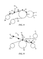
Figure 8 , anapparatus 65 for manufacturing a precursor web is shown which is suitable for the manufacturing of male fasteners in a further apparatus as shown inFigure 9 . The basis of theapparatus 65 is theapparatus 31 shown inFigure 3 . However, theroll 12, thecarrier 13 and theroll 14 are left out. Hence, theapparatus 65 consists of theroll 26, therotary screen device 8 and thesubstrate web 33 wrapped about the mantle surface of theroll 26 and wound onto therolls - For the manufacturing of the precursor web, the
substrate web 33 is unwound from theroll 35 and simultaneously wound onto theroll 34 by counter-clockwise rotation ofroll 26. Simultaneously, therotary screen 9 of therotary screen device 8 rotates clockwise with the same circumferential velocity as theroll 26. Polymer material is fed to the interior of therotary screen 9 as described above and squeezed through theholes 10 of therotary screen 9, thereby depositingdiscrete preform projections 20 with terminal ends 22 forming drop-like projections with a convex mantle surface. When leaving the nip between therotary screen 9 and theroll 26, theprecursor web 66 is formed and allowed to cool sufficiently so that it can be wound onto theroll 34 without affecting the form of thepreform projections 20. At the end of this process, theroll 34 with theentire precursor web 66 being wound up, can be removed from theapparatus 65 and transported to another location where it can be used for the manufacture of male fasteners. -
Figure 9 shows anapparatus 71 for manufacturing male fasteners using aprecursor web 66 produced with theapparatus 65 shown inFigure 8 . Theapparatus 71 comprises aroll 72. Its rotational axis extends perpendicularly to the drawing plane. On the right side of theroll 72, theroll 34 with theprecursor web 66 is disposed rotatably. The already unwound part of theprecursor web 66 is wrapped about the mantle surface of theroll 72 and the web itself is then wound onto aroll 73. Above theroll 34, anotherroll 74 is disposed having a rotational axis extending parallel to the rotational axis of therolls carrier web 13 is wound onto theroll 74, and its already unwound part is fed to thehead 43 of thesonic welding unit 42 which is disposed opposite to the mantle surface of theroll 72. - For the manufacturing of male fasteners, the
roll 72 is rotated counter-clockwise and theprecursor web 66 is drawn from theroll 34, thepreform projections 20 being on the side of theprecursor web 66 opposite to thefront surface 21 of thecarrier web 13. Thecarrier web 13 is drawn from theroll 74 and passes about thehead 43 of thesonic welding unit 42 forming a gap between thefront surface 21 and theprecursor web 66 that is small enough so that thefront surface 21 contacts the terminal ends 22 of thepreform projections 20. Thereby, the terminal ends 22 are re-melted and thefront surface 21 of thecarrier web 13 is melted at the spots where it contacts the terminal ends 22 of thepreform projections 20. The bonding between thefront surface 21 of thecarrier web 13 and the terminal ends 22 of thepreform projections 20 is so strong that thepreform projections 20 are separated from theprecursor web 66 when thecarrier web 13 leaves the gap, thereby forming discrete cup-like fastening members 23 having flat terminal ends 23a. Thereafter, thecarrier web 13 provided with thefastening members 23 can be collected preferable by coiling up onto a roll (not shown). -
Figures 10a through 10g show different forms ofcavities cavity 81 has a circular shape, thecavity 82 an oval shape, the cavity 83 a regular hexagonal shape with equal side length, thecavity 84 has an elongated hexagonal shape and thecavities Figures 10a through 10g show only the boarders of thecavities 81 through 87 and not the shape of the interior of thecavities 81 through 87. - Of course, through
holes 10 of therotary screen 9 shown in theFigures 1 through 8 can have such shapes which result in corresponding shapes of thepreform projections 20 and hence offastening members 23. It is possible that onerotary screen 9 orprinting roll 16 may have cavities or through holes with different shapes. -
Figure 11 shows afastener web 91 comprising acarrier 13 with afront surface 21 onto which a multiplicity of discrete polymeric fastening members is bonded in two parallel extendingcontinuous stripes stripes similar fastener web 94 is shown inFigure 12 where a multiplicity of polymeric fastening members are bonded onto thefront surface 21 inintermittent stripes patterns 97 are formed. In bothFigures 11 and 12 , the dottedlines pattern 97 and a larger area right to thepattern 97 for bonding onto the diaper. Thecontinuous stripes Fig. 11 and theintermittent stripes Fig. 12 , respectively, comprise a multitude of individual fastening members as is indicated in Fig.'s11 and 12. -
Figure 13 shows afastener web 101 comprising acarrier 13 with afront surface 21. In the oval and heart-like areas indicate the areas, a multiplicity of discrete polymeric fastening members is bonded onto thefront surface 21. The repeatingpatterns 102 consist of seven heart-like areas and two oval areas, respectively. The heart-like areas have a lower density of fastening members and the oval areas have a higher density. A dottedline 103 indicates the cut line for the final pad. It is noteworthy that the final pad does not have fastening members in the edge areas of the pad that could cause skin irritation. Thefastener web 101 comprises a multitude of individual fastening members as is indicated inFigure 13 .
Claims (17)
- A method for forming a fastener having fastener members (23, 63), particularly a male fastener for a hook and loop fastening system, comprising:providing a carrier (13, 62) with a front surface (21);providing a contact release surface (7, 27, 32);providing a deposition device (8, 15) having a plurality of cavities (10, 18);providing a polymer material heated to a molten state;filling said molten polymer material into said cavities (10, 18);depositing said molten polymer material from said cavities (10, 18) onto said contact release surface (7, 27, 32) having a temperature below the softening or melting temperature of said molten polymer material, thereby forming preform projections (20, 60) sitting on and projecting from the contact release surface (7, 27, 32) to their corresponding terminal ends(22,61);said preform projections (20, 60) being in contact with the contact release surface (7, 27, 32) for a time sufficient to solidify next to the contact release surface (7, 27, 32);contacting the front surface (21) of the carrier (13, 62) with the terminal ends (22, 61) of said preform projections (20, 60) and bonding them to the carrier (13, 62);separating the preform projections (20, 60) from the contact release surface (7, 27, 32); andthereby forming fastening members (23, 63) projecting from the front surface (21) of the carrier (13, 62).
- The method of claim 1, characterized in that the terminal ends (22, 61) of said preform projections (20, 60) are still molten or semi-molten, when they contact the front surface (21) of the carrier (13, 62).
- The method of claim 1, characterized in that at least some of said preform projections (20, 60) are in contact with the contact release surface (7, 27, 32) for a time sufficient to solidify completely and then at least the terminal ends (22, 61) of the preform projections (20, 60) are re-melted to a semi-molten or molten status before and/or while contacting them with the front surface (21) of the carrier (13, 62).
- The method of claim 3, characterized in that the terminal ends (22, 61) of the preform projections (20, 60) are heated in a region, where the front surface (21) of the carrier (13, 62) is coming into contact with said terminal ends (22,61).
- The method of any of the preceding claims, characterized in that the front surface (21) of the carrier (13, 62) is heated at least to the softening temperature of the polymer material in the region, where the preform projections (20, 60) come into contact with the carrier (13, 62).
- The method of any of the preceding claims, characterized in that a first polymer material is used for forming the preform projections (20, 60) and that at least the front surface (21) of the carrier (13, 62) is formed out of a second material different in at least one property than the first material.
- The method of any of the preceding claims, characterized in that the preform projections (20, 60) are formed so that the fastening members (23, 63) bonded onto the front surface (21) of the carrier (13, 62) have an attached end area and at the terminal end (23a, 63a) a top surface area wherein the attached end area is smaller than the top surface area and wherein the fastening members (23, 63) have a mantle surface extending between the terminal end (23a, 63a) and the attached end which at least partially tapers in the direction to the attached end and has, for example, a convex, particularly lenticular or cup-type, essentially straight and/or concave shape.
- The method of any of the preceding claims, characterized in that the terminal ends (23a, 63a) of at least some fastening members (23, 63) bonded onto the front surface (21) of the carrier (13, 62) are deformed, particularly by re-heating them and then contacting them with a shaping surface of a shaping device.
- A method for forming a precursor web (66) for manufacturing a fastener, particularly a male fastener for a hook and loop fastening system, comprising:providing a substrate web (33) with a contact release surface (32);providing a deposition device (8, 15) having a plurality of cavities (10, 18);providing a polymer material heated to a molten state;filling said molten polymer material into said cavities (10, 18);depositing said molten polymer material from said cavities (10, 18) onto said contact release surface (32) having a temperature below the softening or the melting temperature of said molten polymer material, thereby forming preform projections (20) sitting on and projecting from the contact release surface (32) to their corresponding terminal ends (22);said preform projections (20) being in contact with the contact release surface (32) preferable for a time sufficient to solidify completely, thereby forming a precursor web (66) from which the preform projections (20) are releasable;removing the precursor web (66) off the deposition device (8, 15), particularly by winding up the precursor web (66) onto a roll (34).
- The method of claim 9, characterized in that the preform projections (20) are formed to have a mantle surface extending between a terminal end (22) and an attached end, the mantle surface at least partially tapering between the attached end and the terminal end in the direction to the terminal end (22), whereby the mantle surface has, for example, a convex, particularly a lenticular or cup-type, essentially straight and/or concave shape.
- The method of any of the preceding claims, characterized in that a contact release surface (7) is provided as a closed loop that is moved around at least two rolls (2, 3) in the path of the deposition device (8, 15) or that the contact release surface (27) is provided as a rotating roll (26) with its mantle surface next to the deposition device (8, 15), or that the contact release surface (32) is embodied as a substrate web (33) of finite extension wound onto a roll (35) and moved by uncoiling from the roll (35) and being guided along the deposition device (8, 15) with the contact release surface (32) of the substrate web (33) next to the deposition device (8, 15).
- The method of any of the preceding claims, characterized in that a deposition device is provided embodied as a printing device (15) having a printing roll (16) with cavities (18) on its mantle surface (17) or having a rotary screen (9) with holes (10) as cavities.
- A fastener web (91, 94,101) for engaging with a loop fabric, comprising a carrier (13, 62) with a front surface (21), onto which a multiplicity of discrete polymeric fastening members (23, 63) is bonded in a repeating pattern (97, 102), said fastening members (23, 63) having a terminal end (23a, 63a) with a top surface and an attached end, and having a mantle surface extending between the top surface and the attached end, the mantle surface at least partially tapering from the top surface to the attached end in the direction to the attached end.
- The fastener web of claim 13, characterized in that the fastening members (23, 63) have an attached end area and at the terminal end (23a, 63a) a top surface area, the attached end area being smaller than the top surface area, said fastening members (23, 63) having a mantle surface extending between the terminal end (23a, 63a) and the attached end, whereby the mantle surface at least partially tapers in the direction to the attached end and has, for example, a convex, particularly lenticular or cup-type, essentially straight and/or concave shape.
- The fastener web of claim 13 or 14, characterized in that the top surfaces of the fastening members (23, 63) are substantially flat and/or structured and/or that they have a shape that is substantially round, oval, hexagonal or star-like.
- A precursor web (66) for manufacturing a fastener, particularly a male fastener for a hook and loop fastener, comprising a substrate web (33) with a contact release surface (32), onto which a multiplicity of discrete preform projections (20, 60) formed out of a polymer material are releasably bonded in a repeating pattern, said preform projections (20, 60) having a terminal end (22, 61) with a top surface, an attached end and a mantle surface extending between the top surface and the attached end surface and being tapered from the attached end to the top surface.
- The hygiene article or an absorbent article comprising a fastener or a fastener web of any of the preceding claims.
Priority Applications (7)
| Application Number | Priority Date | Filing Date | Title |
|---|---|---|---|
| EP12173686.2A EP2679112A1 (en) | 2012-06-26 | 2012-06-26 | Method for manufacturing fasteners and precursor webs, a fastener and a precursor web |
| BR112014032379A BR112014032379A2 (en) | 2012-06-26 | 2013-06-24 | method for making precursor closures and webs, a closure and a precursor blanket |
| CN201380034359.4A CN104661552B (en) | 2012-06-26 | 2013-06-24 | Method of making fastener and precursor web, fastener and precursor web |
| US14/410,462 US9883718B2 (en) | 2012-06-26 | 2013-06-24 | Method for manufacturing fasteners and precursor webs, a fastener and a precursor web |
| PCT/US2013/047326 WO2014004379A1 (en) | 2012-06-26 | 2013-06-24 | Method for manufacturing fasteners and precursor webs, a fastener and a precursor web |
| TW102122564A TWI601492B (en) | 2012-06-26 | 2013-06-25 | Method for manufacturing fasteners and precursor webs, a fastener and a precursor web |
| US15/851,796 US20180116346A1 (en) | 2012-06-26 | 2017-12-22 | Method for manufacturing fasteners and precursor webs, a fastener and a precursor web |
Applications Claiming Priority (1)
| Application Number | Priority Date | Filing Date | Title |
|---|---|---|---|
| EP12173686.2A EP2679112A1 (en) | 2012-06-26 | 2012-06-26 | Method for manufacturing fasteners and precursor webs, a fastener and a precursor web |
Publications (1)
| Publication Number | Publication Date |
|---|---|
| EP2679112A1 true EP2679112A1 (en) | 2014-01-01 |
Family
ID=48741587
Family Applications (1)
| Application Number | Title | Priority Date | Filing Date |
|---|---|---|---|
| EP12173686.2A Withdrawn EP2679112A1 (en) | 2012-06-26 | 2012-06-26 | Method for manufacturing fasteners and precursor webs, a fastener and a precursor web |
Country Status (6)
| Country | Link |
|---|---|
| US (2) | US9883718B2 (en) |
| EP (1) | EP2679112A1 (en) |
| CN (1) | CN104661552B (en) |
| BR (1) | BR112014032379A2 (en) |
| TW (1) | TWI601492B (en) |
| WO (1) | WO2014004379A1 (en) |
Cited By (5)
| Publication number | Priority date | Publication date | Assignee | Title |
|---|---|---|---|---|
| EP2946756A1 (en) * | 2014-05-19 | 2015-11-25 | 3M Innovative Properties Company | Rolls for manufacture of fastening tabs |
| DE102016117988A1 (en) | 2016-09-23 | 2018-03-29 | Lohmann-Koester Gmbh & Co. Kg | Male component of a two-component closure system and method and apparatus for making such a component |
| WO2020127645A1 (en) * | 2018-12-20 | 2020-06-25 | Velcro BVBA | Molding fastener products |
| US10779618B2 (en) | 2016-08-08 | 2020-09-22 | 3M Innovative Properties Company | Sheet of loop material, method and apparatus for forming same |
| EP3981569A1 (en) * | 2017-12-21 | 2022-04-13 | Velcro IP Holdings LLC | Molding resin to form continuous structures |
Families Citing this family (13)
| Publication number | Priority date | Publication date | Assignee | Title |
|---|---|---|---|---|
| US10632736B2 (en) * | 2016-02-05 | 2020-04-28 | The Procter & Gamble Company | Systems and methods of applying compositions to webs |
| HUP1600341A2 (en) * | 2016-05-26 | 2017-11-28 | Flexinnova Kft | Antislip flexible materials and methods for their making and use |
| US11876941B1 (en) | 2016-06-20 | 2024-01-16 | Pipbin, Inc. | Clickable augmented reality content manager, system, and network |
| US10334134B1 (en) | 2016-06-20 | 2019-06-25 | Maximillian John Suiter | Augmented real estate with location and chattel tagging system and apparatus for virtual diary, scrapbooking, game play, messaging, canvasing, advertising and social interaction |
| US11201981B1 (en) | 2016-06-20 | 2021-12-14 | Pipbin, Inc. | System for notification of user accessibility of curated location-dependent content in an augmented estate |
| US11785161B1 (en) | 2016-06-20 | 2023-10-10 | Pipbin, Inc. | System for user accessibility of tagged curated augmented reality content |
| US10805696B1 (en) | 2016-06-20 | 2020-10-13 | Pipbin, Inc. | System for recording and targeting tagged content of user interest |
| US10638256B1 (en) | 2016-06-20 | 2020-04-28 | Pipbin, Inc. | System for distribution and display of mobile targeted augmented reality content |
| US11044393B1 (en) | 2016-06-20 | 2021-06-22 | Pipbin, Inc. | System for curation and display of location-dependent augmented reality content in an augmented estate system |
| US10349707B2 (en) * | 2016-07-05 | 2019-07-16 | Alfatex Nv | Fastener tape |
| GB2582968B (en) | 2019-04-12 | 2022-04-06 | Prym Intimates Group Ltd | Adherent fastening product and manufacture thereof |
| EP4388308A1 (en) * | 2021-08-19 | 2024-06-26 | Magna International Inc. | Quality monitoring of welding process |
| WO2025045367A1 (en) * | 2023-08-31 | 2025-03-06 | Essity Hygiene And Health Aktiebolag | Hook-type attachment layer, and a sensor strip with such an attachment layer |
Citations (20)
| Publication number | Priority date | Publication date | Assignee | Title |
|---|---|---|---|---|
| US5325569A (en) | 1992-10-30 | 1994-07-05 | The Procter & Gamble Company | Refastenable mechanical fastening system having particular viscosity and rheology characteristics |
| US5326415A (en) | 1991-06-21 | 1994-07-05 | The Procter & Gamble Company | Screen printing method for manufacturing a refastenable mechanical fastening system and fastening system produced therefrom |
| US5392498A (en) | 1992-12-10 | 1995-02-28 | The Proctor & Gamble Company | Non-abrasive skin friendly mechanical fastening system |
| US5628952A (en) * | 1993-06-30 | 1997-05-13 | Minnesota Mining And Manufacturing Company | Precisely shaped particles and method of making the same |
| US5679302A (en) | 1990-09-21 | 1997-10-21 | Minnesota Mining And Manufacturing Company | Method for making a mushroom-type hook strip for a mechanical fastener |
| US5868987A (en) | 1997-06-19 | 1999-02-09 | Minnesotamining And Manufacturing | Superimposed embossing of capped stem mechanical fastener structures |
| US5879604A (en) | 1990-09-21 | 1999-03-09 | Minnesota Mining And Manufacturing Company | Method of making a mushroom-type hook strip for a mechanical fastener |
| WO2000000053A1 (en) | 1998-06-29 | 2000-01-06 | Gottlieb Binder Gmbh & Co. | Method for producing a fixing closure element |
| US6132660A (en) | 1997-06-19 | 2000-10-17 | 3M Innovative Properties Company | Method for forming headed stem mechanical fasteners |
| WO2001033989A1 (en) | 1999-11-09 | 2001-05-17 | Mandzsu Jozsef Sen | Method and apparatus for producing the male component of a separable fastener, the product produced in this manner and the system containing this product |
| US6248276B1 (en) | 1999-01-15 | 2001-06-19 | Velcro Industries B.V. | Fasteners and methods of making fasteners |
| US20010016245A1 (en) | 1999-02-25 | 2001-08-23 | 3M Innovative Properties Company | Web having discrete stem regions |
| US6592800B1 (en) | 1999-10-04 | 2003-07-15 | 3M Innovative Properties Company | Apparatus and method for making a mechanical fastener |
| US20040031130A1 (en) | 1999-01-15 | 2004-02-19 | Clarner Mark A. | Hook and loop fastener |
| US20040178544A1 (en) * | 2003-03-13 | 2004-09-16 | Jackson Byron M. | Polymer transfer apparatus, methods, and composite webs |
| WO2006099000A2 (en) | 2005-03-11 | 2006-09-21 | 3M Innovative Properties Company | Methods for making fasteners |
| US20080060173A1 (en) * | 2006-09-11 | 2008-03-13 | 3M Innovative Properties Company | Methods for making fasteners |
| WO2008033816A1 (en) * | 2006-09-11 | 2008-03-20 | 3M Innovative Properties Company | Abrasive articles having mechanical fasteners |
| US20080178436A1 (en) | 2007-01-25 | 2008-07-31 | 3M Innovative Properties Company | Fastener webs with microstructured particles and methods of making same |
| DE102007015441A1 (en) * | 2007-03-30 | 2008-10-02 | Gottlieb Binder Gmbh & Co. Kg | Method for producing an adhesive closure part together with the device and subsequently produced adhesive closure part |
Family Cites Families (113)
| Publication number | Priority date | Publication date | Assignee | Title |
|---|---|---|---|---|
| US3426400A (en) | 1966-12-29 | 1969-02-11 | Anthony Lauro | Plastic hook and eye fastener apparatus |
| US3461513A (en) | 1967-02-20 | 1969-08-19 | American Velcro Inc | Separable fastening device |
| US3536518A (en) | 1967-03-10 | 1970-10-27 | Johnson & Johnson | Method of applying print pattern of resin to fibrous sheet material |
| US3550223A (en) | 1967-12-22 | 1970-12-29 | American Velcro Inc | Separable fastening device and method of making same |
| US3562044A (en) | 1968-03-12 | 1971-02-09 | Velcro Sa Soulie | Apparatus and method for manufacture of fabric-like pile products |
| LU59917A1 (en) | 1969-01-24 | 1970-01-28 | ||
| US3594863A (en) | 1969-07-10 | 1971-07-27 | American Velcro Inc | Apparatus for molding plastic shapes in molding recesses formed in a moving endless belt |
| US3594865A (en) | 1969-07-10 | 1971-07-27 | American Velcro Inc | Apparatus for molding plastic shapes in molding recesses formed in moving endless wire dies |
| US3629032A (en) | 1969-07-15 | 1971-12-21 | American Velcro Inc | Method for making flexible strips of material having on one surface thereof a pile of upstanding hooking elements |
| US3708833A (en) | 1971-03-15 | 1973-01-09 | American Velcro Inc | Separable fastening device |
| CH530187A (en) | 1971-03-26 | 1972-11-15 | Repla Internat S A H | Method of manufacturing a fastening device |
| US3708382A (en) | 1971-06-24 | 1973-01-02 | American Velcro Inc | Hooked surface of a hook and loop type fastener |
| US4198734A (en) | 1972-04-04 | 1980-04-22 | Brumlik George C | Self-gripping devices with flexible self-gripping means and method |
| JPS512512A (en) | 1974-06-25 | 1976-01-10 | Toray Industries | KOBANINSATSUYOGENSHI |
| US4169303A (en) | 1976-11-24 | 1979-10-02 | Lemelson Jerome H | Fastening materials |
| FR2432108A1 (en) | 1978-07-25 | 1980-02-22 | Aplix Sa | Fastening tape for fibrous material - has series of barbed spikes on rear surface made from transversely cut extruded plastics sections |
| US4215257A (en) | 1978-11-20 | 1980-07-29 | Otto Engineering, Inc. | Precision toggle switch |
| JPS60843B2 (en) | 1979-04-05 | 1985-01-10 | ワイケイケイ株式会社 | Velvet fastener tape |
| JPS60842B2 (en) | 1979-04-05 | 1985-01-10 | ワイケイケイ株式会社 | Velvet fastener tape and its manufacturing method |
| JPS55137942A (en) | 1979-04-15 | 1980-10-28 | Matsushita Electric Works Ltd | Molding device for plastic sheet having projection |
| JPS6027281B2 (en) | 1979-05-09 | 1985-06-28 | ワイケイケイ株式会社 | Method for manufacturing velvet fastener tape |
| US4462784A (en) | 1979-09-07 | 1984-07-31 | Dennison Manufacturing Company | Apparatus for continuous molding |
| DE3024391A1 (en) | 1980-06-28 | 1982-01-28 | Letron GmbH, 8750 Aschaffenburg | METHOD FOR PRODUCING FILMS FROM PRINTED DECORATION PAPERS |
| US4454183A (en) | 1982-02-26 | 1984-06-12 | Minnesota Mining And Manufacturing Company | Strip material with heat-formed hooked heads |
| DE3401588A1 (en) | 1983-02-01 | 1984-08-02 | Molins PLC, London | DEVICE FOR APPLYING ADHESIVE |
| DE3346100A1 (en) | 1983-12-21 | 1985-07-04 | Beiersdorf Ag, 2000 Hamburg | RESIDUE-FREE RE-DETACHABLE ADHESIVE SURFACES |
| US4775310A (en) | 1984-04-16 | 1988-10-04 | Velcro Industries B.V. | Apparatus for making a separable fastener |
| US4672893A (en) | 1985-03-21 | 1987-06-16 | Paramount Packaging | Flexo-gravure printing |
| US4931343A (en) | 1985-07-31 | 1990-06-05 | Minnesota Mining And Manufacturing Company | Sheet material used to form portions of fasteners |
| US4699622A (en) | 1986-03-21 | 1987-10-13 | The Procter & Gamble Company | Disposable diaper having an improved side closure |
| US4725221A (en) | 1986-05-23 | 1988-02-16 | John H. Blanz Company, Inc. | Improved machine for continuously producing an element of a separable fastener |
| US4776068A (en) | 1986-10-20 | 1988-10-11 | Velcro Industries B. V. | Quiet touch fastener material |
| DE3638307A1 (en) | 1986-11-10 | 1988-05-19 | Volker Ludwig | DEVICE FOR APPLYING LIQUID, PASTOESE OR PLASTIC SUBSTANCES TO A SUBSTRATE |
| PT86585B (en) | 1987-01-26 | 1991-12-31 | Procter & Gamble | DISCHARGEABLE FRAGMENT POSSESSING A TYPE OF CLOSURE BY IMPROVED FIXATION |
| US4846815A (en) | 1987-01-26 | 1989-07-11 | The Procter & Gamble Company | Disposable diaper having an improved fastening device |
| US4829641A (en) | 1987-06-22 | 1989-05-16 | First Brands Corporation | Enhanced color change interlocking closure strip |
| DE3721593A1 (en) | 1987-06-30 | 1989-01-26 | Henning J Claassen | DEVICE FOR APPLYING LIQUID ADHESIVES TO A SUBSTRATE |
| US4973326A (en) | 1987-11-30 | 1990-11-27 | Minnesota Mining And Manufacturing Company | Disposable diaper with improved fastener attachment |
| CA1311589C (en) | 1987-12-17 | 1992-12-22 | Charles Locke Scripps | Disposable absorbent article with combination mechanical and adhesive tape fastener system |
| US4894060A (en) | 1988-01-11 | 1990-01-16 | Minnesota Mining And Manufacturing Company | Disposable diaper with improved hook fastener portion |
| DE3808295A1 (en) | 1988-03-12 | 1989-09-21 | Schaefer Marburger Tapeten | METHOD AND PLANT FOR PRODUCING DECOR GRANULES AND USE OF THESE GRANULATES |
| DE3813756C1 (en) | 1988-04-23 | 1989-03-02 | Santrade Ltd., Luzern, Ch | |
| CA1340190C (en) | 1988-08-01 | 1998-12-15 | The Kendall Company | Discontinuous adhesive surface |
| US4984339A (en) | 1988-10-20 | 1991-01-15 | Velcro Industries B.V. | Hook for hook and loop fasteners |
| US5019073A (en) | 1988-12-20 | 1991-05-28 | Kimberly-Clark Corporation | Disposable diaper with improved mechanical fastening system |
| US5058247A (en) | 1989-01-31 | 1991-10-22 | The Procter & Gamble Company | Mechanical fastening prong |
| US5180534A (en) | 1990-12-21 | 1993-01-19 | The Procter & Gamble Company | Process of manufacturing a refastenable mechanical fastening system |
| FI95643C (en) | 1989-01-31 | 1996-03-11 | Procter & Gamble | Method of forming a fastening system |
| US5540673A (en) | 1989-01-31 | 1996-07-30 | The Procter & Gamble Company | Refastenable mechanical fastening system |
| US5230851A (en) | 1989-01-31 | 1993-07-27 | The Procter & Gamble Company | Process of manufacturing a refastenable mechanical fastening system |
| DE3905342A1 (en) | 1989-02-22 | 1990-08-23 | Volker Ludwig | METHOD AND DEVICE FOR APPLYING LIQUID, PASTOESE OR PLASTIC SUBSTANCES TO A SUBSTRATE |
| ES2069615T3 (en) | 1989-03-24 | 1995-05-16 | Paragon Trade Brands Inc | DISPOSABLE DIAPER WITH A READJUSTABLE MECHANICAL HOLDING SYSTEM. |
| CA2013950C (en) | 1989-04-07 | 1994-08-16 | Panos Trakas | Integrally heated torpedo |
| US5100400A (en) | 1989-11-17 | 1992-03-31 | Minnesota Mining And Manufacturing Company | Disposable diaper with thermoplastic material anchored hook fastener portion |
| CA2023043A1 (en) | 1990-04-02 | 1991-10-03 | Anne M. Fahrenkrug | Diaper having disposable chassis assembly and reusable elasticized belt removably retained by said chassis assembly |
| US5040275A (en) | 1990-06-01 | 1991-08-20 | Minnesota Mining And Manufacturing Company | Strip material used for forming fasteners |
| US5116563A (en) | 1990-06-28 | 1992-05-26 | The Procter & Gamble Company | Process for producing a mechanical fastener |
| JPH0458322A (en) | 1990-06-28 | 1992-02-25 | Nec Corp | Preceding '1' detecting circuit |
| JPH0431512U (en) | 1990-07-03 | 1992-03-13 | ||
| DE69111347T2 (en) | 1990-09-21 | 1996-04-11 | Minnesota Mining & Mfg | Mechanical connection and diaper construction. |
| HK1008721A1 (en) | 1991-05-20 | 1999-05-14 | The Procter & Gamble Company | Multilayer female component for refastenable fastening device |
| US5260015A (en) | 1991-08-16 | 1993-11-09 | Velcro Industries, B.V. | Method for making a laminated hook fastener |
| US5520676A (en) | 1991-10-01 | 1996-05-28 | The Procter & Gamble Company | Absorbent article having a unitary release member joined to a flap retaining member |
| JP2744384B2 (en) | 1992-07-22 | 1998-04-28 | ワイケイケイ株式会社 | Method and apparatus for manufacturing engaging member having back member on back surface |
| US5315740A (en) | 1992-08-20 | 1994-05-31 | Velcro Industries, B.V. | Hook for hook and loop fasteners |
| US5720740A (en) | 1993-04-07 | 1998-02-24 | The Procter & Gamble Company | Refastenable mechanical fastening system attached to substrate protrusion |
| US5385706A (en) | 1993-04-07 | 1995-01-31 | The Proctor & Gamble Company | Process of making a refastenable mechanical fastening system with substrate having protrusions |
| CA2163331A1 (en) | 1993-05-25 | 1994-12-08 | Dennis Albert Thomas | Method for manufacturing a refastenable mechanical fastening system having azimuthally angled prongs and fastening system produced therefrom |
| JP3298887B2 (en) | 1993-06-11 | 2002-07-08 | ミネソタ マイニング アンド マニュファクチャリング カンパニー | Laser processing duplication tool |
| SE501513C2 (en) | 1993-06-14 | 1995-03-06 | Moelnlycke Ab | Hook and loop type connection - has hook layer with protrusions made of plastics as is support from which protrusion extends outwardly |
| US5762645A (en) | 1994-06-06 | 1998-06-09 | The Procter & Gamble Company | Fastening device and method of use |
| US5586371A (en) | 1994-11-08 | 1996-12-24 | The Procter & Gamble Company | Method for manufacturing refastenable fastening systems including a female loop fastening component and the product produced therefrom |
| USH1738H (en) | 1995-01-05 | 1998-07-07 | The Procter & Gamble Company | Tear resistant disposable bib |
| US5636414A (en) | 1995-02-24 | 1997-06-10 | Litchholt; John J. | Two mechanism mechanical fastener |
| US5715542A (en) | 1995-08-10 | 1998-02-10 | The Procter & Gamble Company | Bib having an improved fastener |
| US6401081B1 (en) | 1995-11-20 | 2002-06-04 | Schlumberger Resource Management Services, Inc. | Modular object-based architecture for extensible master station software |
| WO1998029003A1 (en) | 1996-12-30 | 1998-07-09 | Leonard Duffy | Interlocking device |
| US6605332B2 (en) | 1997-07-29 | 2003-08-12 | 3M Innovative Properties Company | Unitary polymer substrate having napped surface of frayed end microfibers |
| ES2229545T3 (en) * | 1997-10-31 | 2005-04-16 | Kimberly-Clark Worldwide, Inc. | MATERIALS NON-FABRICED, RIPPED AND COATING. |
| GB9816472D0 (en) | 1998-07-30 | 1998-09-23 | Ariel Ind Plc | Multiple fastener application system |
| DE69905059T2 (en) | 1998-10-02 | 2003-11-20 | 3M Innovative Properties Co., Saint Paul | ELASTIC COMPOSITES |
| US7048818B2 (en) | 2000-03-14 | 2006-05-23 | Velcro Industries B.V. | Hook and loop fastening |
| US6303062B1 (en) | 1999-04-13 | 2001-10-16 | 3M Innovative Properties Company | Mechanical fastener and method for making the same |
| US6613033B1 (en) | 2000-08-15 | 2003-09-02 | Kimberly-Clark Worldwide, Inc. | Pant-like absorbent garments having curved leg cuffs |
| US6652504B1 (en) | 2000-08-15 | 2003-11-25 | Kimberly-Clark Worldwide, Inc. | Pant-like absorbent garments having curved leak guard flaps |
| US6375769B1 (en) | 2000-08-15 | 2002-04-23 | Kimberly-Clark Worldwide, Inc. | Method of applying curved leg elastics using pucks with curved surfaces |
| US6585841B1 (en) | 2000-08-15 | 2003-07-01 | Kimberly-Clark Worldwide, Inc. | Method of optimizing spacing between elastic members in applying leg elastics |
| US6635041B1 (en) | 2000-08-15 | 2003-10-21 | Kimberly-Clark Worldwide, Inc. | Absorbent garment with asymmetrical leg elastic tension |
| US6540857B1 (en) | 2000-08-15 | 2003-04-01 | Kimberly-Clark Worldwide, Inc. | Method of applying curved leg elastics using curved pucks |
| US6569275B1 (en) | 2000-08-15 | 2003-05-27 | Kimberly-Clark Worldwide, Inc. | Method of optimizing tension in applying leg elastics |
| US6689115B1 (en) | 2000-08-15 | 2004-02-10 | Kimberly-Clark Worldwide, Inc. | Absorbent garment with asymmetrical leg elastic spacing |
| US6440246B1 (en) | 2000-08-15 | 2002-08-27 | Kimberly-Clark Worldwide, Inc. | Method of applying curved leg elastics using rotating disks |
| US7162780B2 (en) | 2001-02-26 | 2007-01-16 | Velcro Industries B.V. | Skin-friendly hook fastening component |
| US7578812B2 (en) | 2001-03-01 | 2009-08-25 | Kimberly-Clark Worldwide, Inc. | Pre-fastened absorbent article having simplified fastening features |
| US7785095B2 (en) | 2001-03-14 | 2010-08-31 | Velcro Industries B.V. | Molding apparatus and related methods |
| DE60115859T2 (en) | 2001-06-02 | 2006-08-17 | The Procter & Gamble Company, Cincinnati | Process for printing adhesives, adhesives and gravure rolls |
| WO2003000483A1 (en) | 2001-06-23 | 2003-01-03 | Spaeth Bernd | Body with improved surface properties |
| US6942894B2 (en) | 2001-11-05 | 2005-09-13 | 3M Innovative Properties Company | Methods for producing composite webs with reinforcing discrete polymeric regions |
| US7037457B2 (en) | 2001-11-05 | 2006-05-02 | 3M Innovative Properties Company | Systems and methods for composite webs with structured discrete polymeric regions |
| US6964063B2 (en) | 2002-09-28 | 2005-11-15 | Bamber Jeffrey V | Sports glove |
| US7344525B2 (en) | 2002-11-22 | 2008-03-18 | Kimberly-Clark Worldwide, Inc. | Absorbent article with improved fastening system |
| US7520033B2 (en) | 2003-10-15 | 2009-04-21 | Velcro Industries B.V. | Multiple-crook male touch fastener elements |
| US7716792B2 (en) | 2003-10-15 | 2010-05-18 | Velero Industries B.V. | Touch fastener elements |
| US7373699B2 (en) | 2003-10-15 | 2008-05-20 | Velcro Industries B.V. | Plastic sheet reinforcement |
| US20050132544A1 (en) * | 2003-12-23 | 2005-06-23 | Jayshree Seth | Split hook fastener |
| US7444722B2 (en) | 2004-04-30 | 2008-11-04 | Kimberly-Clark Worldwide, Inc. | Refastenable absorbent garment |
| DE102005040029A1 (en) | 2004-08-23 | 2006-03-09 | Koester Gmbh & Co. Kg | Male fastening component for hook-loop-fastening system, has single-piece mold, where component gives up reversible hook-shape under influence of heat energy or radiation energy and/or presence/absence of humidity or chemical reagents |
| HUP0500291A2 (en) * | 2005-03-11 | 2006-11-28 | 3M Innovative Properties Co | Fasteners, methods for making fasteners and use of fasteners in products |
| US7601284B2 (en) | 2005-04-06 | 2009-10-13 | Velcro Industries B.V. | Molding fastener elements on folded substrate |
| JP5098241B2 (en) | 2006-07-20 | 2012-12-12 | Jnc株式会社 | Liquid crystal composition and liquid crystal display element |
| US7534481B2 (en) | 2006-08-08 | 2009-05-19 | 3M Innovative Properties Company | Shaped elastic tab laminates |
| US8308900B2 (en) | 2006-09-15 | 2012-11-13 | Buckman Laboratories International, Inc. | Methods to control lipophilic extractives in acacia wood pulp and fiber |
| US8709323B2 (en) | 2007-04-11 | 2014-04-29 | Gottlieb Binder Gmbh & Co. Kg | Method for producing an adhesive fastening element made of plastic |
-
2012
- 2012-06-26 EP EP12173686.2A patent/EP2679112A1/en not_active Withdrawn
-
2013
- 2013-06-24 CN CN201380034359.4A patent/CN104661552B/en not_active Expired - Fee Related
- 2013-06-24 US US14/410,462 patent/US9883718B2/en not_active Expired - Fee Related
- 2013-06-24 WO PCT/US2013/047326 patent/WO2014004379A1/en not_active Ceased
- 2013-06-24 BR BR112014032379A patent/BR112014032379A2/en not_active Application Discontinuation
- 2013-06-25 TW TW102122564A patent/TWI601492B/en not_active IP Right Cessation
-
2017
- 2017-12-22 US US15/851,796 patent/US20180116346A1/en not_active Abandoned
Patent Citations (22)
| Publication number | Priority date | Publication date | Assignee | Title |
|---|---|---|---|---|
| US5679302A (en) | 1990-09-21 | 1997-10-21 | Minnesota Mining And Manufacturing Company | Method for making a mushroom-type hook strip for a mechanical fastener |
| US5879604A (en) | 1990-09-21 | 1999-03-09 | Minnesota Mining And Manufacturing Company | Method of making a mushroom-type hook strip for a mechanical fastener |
| US5326415A (en) | 1991-06-21 | 1994-07-05 | The Procter & Gamble Company | Screen printing method for manufacturing a refastenable mechanical fastening system and fastening system produced therefrom |
| US5325569A (en) | 1992-10-30 | 1994-07-05 | The Procter & Gamble Company | Refastenable mechanical fastening system having particular viscosity and rheology characteristics |
| US5392498A (en) | 1992-12-10 | 1995-02-28 | The Proctor & Gamble Company | Non-abrasive skin friendly mechanical fastening system |
| US5628952A (en) * | 1993-06-30 | 1997-05-13 | Minnesota Mining And Manufacturing Company | Precisely shaped particles and method of making the same |
| US5868987A (en) | 1997-06-19 | 1999-02-09 | Minnesotamining And Manufacturing | Superimposed embossing of capped stem mechanical fastener structures |
| US6132660A (en) | 1997-06-19 | 2000-10-17 | 3M Innovative Properties Company | Method for forming headed stem mechanical fasteners |
| WO2000000053A1 (en) | 1998-06-29 | 2000-01-06 | Gottlieb Binder Gmbh & Co. | Method for producing a fixing closure element |
| US6248276B1 (en) | 1999-01-15 | 2001-06-19 | Velcro Industries B.V. | Fasteners and methods of making fasteners |
| US20040031130A1 (en) | 1999-01-15 | 2004-02-19 | Clarner Mark A. | Hook and loop fastener |
| US6708378B2 (en) | 1999-01-15 | 2004-03-23 | Velcro Industries B.V. | Fasteners and methods of making fasteners |
| US20010016245A1 (en) | 1999-02-25 | 2001-08-23 | 3M Innovative Properties Company | Web having discrete stem regions |
| US6592800B1 (en) | 1999-10-04 | 2003-07-15 | 3M Innovative Properties Company | Apparatus and method for making a mechanical fastener |
| WO2001033989A1 (en) | 1999-11-09 | 2001-05-17 | Mandzsu Jozsef Sen | Method and apparatus for producing the male component of a separable fastener, the product produced in this manner and the system containing this product |
| US20040178544A1 (en) * | 2003-03-13 | 2004-09-16 | Jackson Byron M. | Polymer transfer apparatus, methods, and composite webs |
| WO2006099000A2 (en) | 2005-03-11 | 2006-09-21 | 3M Innovative Properties Company | Methods for making fasteners |
| US20080060173A1 (en) * | 2006-09-11 | 2008-03-13 | 3M Innovative Properties Company | Methods for making fasteners |
| WO2008033816A1 (en) * | 2006-09-11 | 2008-03-20 | 3M Innovative Properties Company | Abrasive articles having mechanical fasteners |
| WO2008033629A2 (en) | 2006-09-11 | 2008-03-20 | 3M Innovative Properties Company | Methods for making fasteners |
| US20080178436A1 (en) | 2007-01-25 | 2008-07-31 | 3M Innovative Properties Company | Fastener webs with microstructured particles and methods of making same |
| DE102007015441A1 (en) * | 2007-03-30 | 2008-10-02 | Gottlieb Binder Gmbh & Co. Kg | Method for producing an adhesive closure part together with the device and subsequently produced adhesive closure part |
Cited By (14)
| Publication number | Priority date | Publication date | Assignee | Title |
|---|---|---|---|---|
| EP2946756A1 (en) * | 2014-05-19 | 2015-11-25 | 3M Innovative Properties Company | Rolls for manufacture of fastening tabs |
| WO2015179368A1 (en) * | 2014-05-19 | 2015-11-26 | 3M Innovative Properties Company | Rolls for manufacture of fastening tabs |
| CN106456420A (en) * | 2014-05-19 | 2017-02-22 | 3M创新有限公司 | Rolls for manufacture of fastening tabs |
| EP3145466B1 (en) | 2014-05-19 | 2018-06-20 | 3M Innovative Properties Company | Rolls for manufacture of fastening tabs |
| CN106456420B (en) * | 2014-05-19 | 2020-03-06 | 3M创新有限公司 | Roll for manufacturing fastening tabs |
| EP3145466B2 (en) † | 2014-05-19 | 2023-01-11 | 3M Innovative Properties Company | Rolls for manufacture of fastening tabs |
| US10779618B2 (en) | 2016-08-08 | 2020-09-22 | 3M Innovative Properties Company | Sheet of loop material, method and apparatus for forming same |
| DE102016117988A1 (en) | 2016-09-23 | 2018-03-29 | Lohmann-Koester Gmbh & Co. Kg | Male component of a two-component closure system and method and apparatus for making such a component |
| DE102016117988B4 (en) | 2016-09-23 | 2023-05-25 | Lohmann-Koester Gmbh & Co. Kg | Male component of a two-component closure system and method of manufacturing such a component |
| EP3981569A1 (en) * | 2017-12-21 | 2022-04-13 | Velcro IP Holdings LLC | Molding resin to form continuous structures |
| US11981057B2 (en) | 2017-12-21 | 2024-05-14 | Velcro Ip Holdings Llc | Molding resin to form continuous structures |
| US12202177B2 (en) | 2017-12-21 | 2025-01-21 | Velcro Ip Holdings Llc | Molding resin to form continuous structures |
| US11161283B2 (en) | 2018-12-20 | 2021-11-02 | Velcro Ip Holdings Llc | Molding fastener products |
| WO2020127645A1 (en) * | 2018-12-20 | 2020-06-25 | Velcro BVBA | Molding fastener products |
Also Published As
| Publication number | Publication date |
|---|---|
| US9883718B2 (en) | 2018-02-06 |
| TWI601492B (en) | 2017-10-11 |
| US20150335105A1 (en) | 2015-11-26 |
| BR112014032379A2 (en) | 2017-06-27 |
| WO2014004379A1 (en) | 2014-01-03 |
| CN104661552B (en) | 2018-06-05 |
| US20180116346A1 (en) | 2018-05-03 |
| TW201417733A (en) | 2014-05-16 |
| CN104661552A (en) | 2015-05-27 |
Similar Documents
| Publication | Publication Date | Title |
|---|---|---|
| US9883718B2 (en) | Method for manufacturing fasteners and precursor webs, a fastener and a precursor web | |
| EP1021105B1 (en) | Finger grip for a fastening system and a method of making the same | |
| JP3188459B2 (en) | Method of manufacturing mechanical fastening system capable of refastening and fastening system manufactured by the method | |
| KR100263360B1 (en) | Manufacture method of refastenable fastening system containing female loop fastening components and products manufactured therefrom | |
| JP5180215B2 (en) | Fastener manufacturing method | |
| JP3107804B2 (en) | Method of manufacturing fastening device and fastening device manufactured by the manufacturing method | |
| KR100252434B1 (en) | Sheet material having a fibrous surface and method of making the same | |
| JP6042821B2 (en) | Method for making a structured surface and article obtained therefrom | |
| JP2008532639A (en) | Fastener manufacturing method | |
| JP2010516396A (en) | Fastener web with microstructured particles | |
| JPH06508315A (en) | Method for producing a restackable mechanical fastening system with azimuthal prongs and fastening systems produced by the method | |
| KR0131600B1 (en) | Mechanical fastening prong | |
| HUP0500291A2 (en) | Fasteners, methods for making fasteners and use of fasteners in products | |
| JP2002337215A (en) | Apparatus and method for manufacturing linear resin structural material in which bendable linear three-dimensional projections are arranged on one or both sides | |
| MXPA00000468A (en) | Finger grip for a fastening system and a method of making the same |
Legal Events
| Date | Code | Title | Description |
|---|---|---|---|
| PUAI | Public reference made under article 153(3) epc to a published international application that has entered the european phase |
Free format text: ORIGINAL CODE: 0009012 |
|
| AK | Designated contracting states |
Kind code of ref document: A1 Designated state(s): AL AT BE BG CH CY CZ DE DK EE ES FI FR GB GR HR HU IE IS IT LI LT LU LV MC MK MT NL NO PL PT RO RS SE SI SK SM TR |
|
| AX | Request for extension of the european patent |
Extension state: BA ME |
|
| 17P | Request for examination filed |
Effective date: 20140613 |
|
| RBV | Designated contracting states (corrected) |
Designated state(s): AL AT BE BG CH CY CZ DE DK EE ES FI FR GB GR HR HU IE IS IT LI LT LU LV MC MK MT NL NO PL PT RO RS SE SI SK SM TR |
|
| STAA | Information on the status of an ep patent application or granted ep patent |
Free format text: STATUS: THE APPLICATION HAS BEEN WITHDRAWN |
|
| 18W | Application withdrawn |
Effective date: 20190312 |