JP5180215B2 - Fastener manufacturing method - Google Patents
Fastener manufacturing method Download PDFInfo
- Publication number
- JP5180215B2 JP5180215B2 JP2009528372A JP2009528372A JP5180215B2 JP 5180215 B2 JP5180215 B2 JP 5180215B2 JP 2009528372 A JP2009528372 A JP 2009528372A JP 2009528372 A JP2009528372 A JP 2009528372A JP 5180215 B2 JP5180215 B2 JP 5180215B2
- Authority
- JP
- Japan
- Prior art keywords
- substrate
- particles
- contact
- release surface
- protrusions
- Prior art date
- Legal status (The legal status is an assumption and is not a legal conclusion. Google has not performed a legal analysis and makes no representation as to the accuracy of the status listed.)
- Expired - Fee Related
Links
Images


Classifications
-
- A—HUMAN NECESSITIES
- A44—HABERDASHERY; JEWELLERY
- A44B—BUTTONS, PINS, BUCKLES, SLIDE FASTENERS, OR THE LIKE
- A44B18/00—Fasteners of the touch-and-close type; Making such fasteners
- A44B18/0003—Fastener constructions
- A44B18/0011—Female or loop elements
-
- A—HUMAN NECESSITIES
- A61—MEDICAL OR VETERINARY SCIENCE; HYGIENE
- A61F—FILTERS IMPLANTABLE INTO BLOOD VESSELS; PROSTHESES; DEVICES PROVIDING PATENCY TO, OR PREVENTING COLLAPSING OF, TUBULAR STRUCTURES OF THE BODY, e.g. STENTS; ORTHOPAEDIC, NURSING OR CONTRACEPTIVE DEVICES; FOMENTATION; TREATMENT OR PROTECTION OF EYES OR EARS; BANDAGES, DRESSINGS OR ABSORBENT PADS; FIRST-AID KITS
- A61F13/00—Bandages or dressings; Absorbent pads
- A61F13/15—Absorbent pads, e.g. sanitary towels, swabs or tampons for external or internal application to the body; Supporting or fastening means therefor; Tampon applicators
- A61F13/56—Supporting or fastening means
- A61F13/62—Mechanical fastening means, ; Fabric strip fastener elements, e.g. hook and loop
- A61F13/622—Fabric strip fastener elements, e.g. hook and loop
- A61F13/625—Fabric strip fastener elements, e.g. hook and loop characterised by the hook
-
- Y—GENERAL TAGGING OF NEW TECHNOLOGICAL DEVELOPMENTS; GENERAL TAGGING OF CROSS-SECTIONAL TECHNOLOGIES SPANNING OVER SEVERAL SECTIONS OF THE IPC; TECHNICAL SUBJECTS COVERED BY FORMER USPC CROSS-REFERENCE ART COLLECTIONS [XRACs] AND DIGESTS
- Y10—TECHNICAL SUBJECTS COVERED BY FORMER USPC
- Y10T—TECHNICAL SUBJECTS COVERED BY FORMER US CLASSIFICATION
- Y10T24/00—Buckles, buttons, clasps, etc.
- Y10T24/27—Buckles, buttons, clasps, etc. including readily dissociable fastener having numerous, protruding, unitary filaments randomly interlocking with, and simultaneously moving towards, mating structure [e.g., hook-loop type fastener]
- Y10T24/2708—Combined with diverse fastener
-
- Y—GENERAL TAGGING OF NEW TECHNOLOGICAL DEVELOPMENTS; GENERAL TAGGING OF CROSS-SECTIONAL TECHNOLOGIES SPANNING OVER SEVERAL SECTIONS OF THE IPC; TECHNICAL SUBJECTS COVERED BY FORMER USPC CROSS-REFERENCE ART COLLECTIONS [XRACs] AND DIGESTS
- Y10—TECHNICAL SUBJECTS COVERED BY FORMER USPC
- Y10T—TECHNICAL SUBJECTS COVERED BY FORMER US CLASSIFICATION
- Y10T24/00—Buckles, buttons, clasps, etc.
- Y10T24/27—Buckles, buttons, clasps, etc. including readily dissociable fastener having numerous, protruding, unitary filaments randomly interlocking with, and simultaneously moving towards, mating structure [e.g., hook-loop type fastener]
- Y10T24/2783—Buckles, buttons, clasps, etc. including readily dissociable fastener having numerous, protruding, unitary filaments randomly interlocking with, and simultaneously moving towards, mating structure [e.g., hook-loop type fastener] having filaments constructed from coated, laminated, or composite material
Description
本発明は、ファスナーの製造方法であって、特にフック・アンド・ループ型のファスナーとしても知られているマジックテープ(登録商標)型ファスナーのための雄部材の製造方法に関する。 The present invention relates to a method for manufacturing a fastener, and more particularly to a method for manufacturing a male member for a Velcro (registered trademark) type fastener, also known as a hook and loop type fastener.
使い捨ておむつ、トレーニングパンツ、及び失禁者の下着を着用者に巻きつけて固定するために、特定タイプのフック・アンド・ループ型のメカニカルファスナーを使用するのは一般的である。1つの方法は、雌部材としての低い嵩高性のループ状の材料、好ましくは不織性の布地と合わせて成形される、薄い雄型ファスナーである。これら用途では、一般に、低コスト、柔らかな手触り、適切な強度、及びウェストラインでの高い伸縮性が重要である。 It is common to use certain types of hook and loop type mechanical fasteners to wrap and secure disposable diapers, training pants, and incontinence underwear around the wearer. One method is a thin male fastener that is molded with a low bulky looped material as a female member, preferably a non-woven fabric. In these applications, low cost, soft touch, adequate strength, and high stretch at the waistline are generally important.
フックは、例えば、ベルクロ(登録商標)(Velcro)に譲渡された米国特許第5,315,740号に開示されているようにして直接成形することができ、前記特許には、それらと噛み合わせるために少量のループ状の布地を転置しさえすればよいように、低変位量の成形フックが開示されている。前記特許には、凹角フック、すなわち、その先端部がフックの上端部から基材シートに向かって上から下へ湾曲することで、繊維を保持する凹部をフックの下面で画定するものが開示されている。 The hooks can be molded directly as disclosed, for example, in US Pat. No. 5,315,740 assigned to Velcro, which is in mesh with them. Therefore, a low-displacement molded hook is disclosed so that only a small amount of looped fabric needs to be transposed. The patent discloses a concave hook, i.e., one in which the tip of the hook is curved from top to bottom from the upper end of the hook toward the base sheet, thereby defining a recess for holding the fiber on the lower surface of the hook. ing.
また、成形されたステムをウェブ上に被せることも知られている。この方法で得られるマッシュルーム型の係合突起は、米国特許第5,679,302号及び米国特許第5,879,604号に開示されており、前記特許には、押出成形されたポリマー層を、金型キャビティを有する金型に押圧し、このキャビティによって突出ステムを基材と一体にして作り出す。次に、加熱圧縮ローラーでステムの末端部を変形させて、ループ係合突起を形成する。米国特許第6,054,091号には、同様の方法が開示されているが、加熱変形表面によって、変形中に本質的に横方向の変形をステムにもたらすことにより、平坦な上部部分を有する凹角のJ−型フックが形成される、米国特許第6,627,133号の解決策は、加熱圧縮ローラーで覆われるステム化ウェブが米国特許第6,287,665号の方法で、すなわち、筒状の印刷スクリーンによって構成された特別な金型を用いて製造される点で、前述のものとは異なる。この段落に記載した文献はいずれも、予備成形されたステムをホットロールによって平坦化する点で類似している。 It is also known to put a molded stem on a web. Mushroom-type engaging protrusions obtained by this method are disclosed in US Pat. No. 5,679,302 and US Pat. No. 5,879,604, which include an extruded polymer layer. Then, a mold having a mold cavity is pressed, and a protruding stem is formed integrally with the substrate by the cavity. Next, the end portion of the stem is deformed by a heat compression roller to form a loop engagement protrusion. US Pat. No. 6,054,091 discloses a similar method, but with a heated upper surface that has a flat upper portion by introducing essentially lateral deformation to the stem during deformation. The solution of U.S. Pat. No. 6,627,133, where a concave J-shaped hook is formed, is that the stemmed web covered with a heated compression roller is in the manner of U.S. Pat. No. 6,287,665, i.e. It differs from the above in that it is manufactured using a special mold constituted by a cylindrical printing screen. All of the documents described in this paragraph are similar in that the preformed stem is flattened with a hot roll.
米国特許出願2004/0031130Alには、ポリマー基材と、これと一体化された、基材から突き出ているステムとを含む製品を、複数個の精巧な金型キャビティを有する金型ロールを用いて押出成形する方法が開示されている。その後、ステムの遠位端部は加熱されて融解されるが、その最下部は、低温で保持されて固体状態で維持される。次に、変形表面を用いて融解した端部を平坦化する。同じ方法、すなわち、ステムを予備加熱した後で平坦化することは、米国特許第6,592,800号、米国特許第6,248,276号、及び米国特許第6,708,378号にも掲載されており、後者の2件の特許には更に、粗い接触表面で覆って、係合突起の粗面化した平坦な上部を作り出すことも開示されている。 U.S. Patent Application 2004 / 0031130Al uses a mold roll having a plurality of sophisticated mold cavities to integrate a product comprising a polymer substrate and a stem protruding therefrom that is integral therewith. A method of extruding is disclosed. Thereafter, the distal end of the stem is heated and melted, while its bottom is kept at a low temperature and maintained in a solid state. Next, the melted end is flattened using the deformed surface. The same method, i.e., planarizing the stem after preheating, is described in U.S. Patent No. 6,592,800, U.S. Patent No. 6,248,276, and U.S. Patent No. 6,708,378. The latter two patents also disclose that they are covered with a rough contact surface to create a roughened flat top of the engagement protrusion.
米国特許第6,039,911号には、ステムを徐々に圧縮変形して基材と一体させる長い可変ニップ(例えば、一対の共働コンベヤー)を備えた、ステム変形装置が開示されている。 U.S. Pat. No. 6,039,911 discloses a stem deformation device with a long variable nip (e.g., a pair of cooperating conveyors) that gradually compresses and deforms the stem into one piece with the substrate.
米国特許第6,470,540号では、ステムを変形させるために、熱間押出成形された層が使用されており、その結果、半球形のマッシュルーム状の頭部がもたらされる。 In US Pat. No. 6,470,540, a hot-extruded layer is used to deform the stem, resulting in a hemispherical mushroom head.
米国特許第3,550,837号には、ファスナー雄部材が記載されており、その各係合突起は、接着剤で基材に接着された、特殊な多角表面を有する不規則な形の粒剤で構成されている。ファスナーは、使い捨て紙箱のフタを開口部に固定するのに適している。係合は、多角表面を形成する多数の小さな平坦な平面を含む粒剤によってもたらされる。 U.S. Pat. No. 3,550,837 describes a male fastener member, each engaging projection of which is an irregularly shaped grain having a special polygonal surface bonded to the substrate with an adhesive. Consists of agents. The fastener is suitable for fixing the lid of the disposable paper box to the opening. Engagement is effected by granules containing a number of small flat planes that form a polygonal surface.
米国特許第3,922,455号では、様々な形状の尖端が、直線状の長繊維上に融着されており、その直線状の長繊維は、基材から隆起して、ファスナー雄部材の係合構成要素を形成している。 In U.S. Pat. No. 3,922,455, various shaped tips are fused on a linear long fiber, and the linear long fiber is raised from the base material to form a fastener male member. An engaging component is formed.
PCT国際公開特許WO 01/33989では、粒子が、散布コーターの散布ヘッドを用いて無作為に散布されて、基材に固定されている。各係合突起は、いくつかの凝集粒子によって構成されているが、単体の粒子がいくつか残存している場合もある。 In PCT International Publication No. WO 01/33989, particles are randomly spread using a spreading head of a spreading coater and fixed to a substrate. Each engaging protrusion is composed of several aggregated particles, but some single particles may remain.
したがって、本発明の目的は、有利な特性を有する、低コストの雄型メカニカルファスナーを提供することであった。本発明のもう1つの目的は、現在入手可能なメカニカル雄型ファスナーシステムに対する商業的に魅力のある代替物、及びその製造方法を提供することであった。 Accordingly, it was an object of the present invention to provide a low cost male mechanical fastener having advantageous properties. Another object of the present invention was to provide a commercially attractive alternative to currently available mechanical male fastener systems and methods for their manufacture.
本発明は、前面と裏面とを有する基材を含む、好適なループ状の布地と係合可能なフックファスナーであって、前記面のうち少なくとも一方が、上面と付着端部とを有する複数の係合突起を有する、フックファスナーを提供する。付着端部は基材の表面に固定されており、複数の突起が、1つ以上の形を形成する領域に配置されている。 The present invention is a hook fastener that can be engaged with a suitable loop-like fabric, including a base material having a front surface and a back surface, wherein at least one of the surfaces has a top surface and an attachment end. A hook fastener having an engaging protrusion is provided. The adhering end is fixed to the surface of the substrate, and a plurality of protrusions are disposed in a region forming one or more shapes.
好ましい方法では、静電引力を用いてポリマー粒子類を接触剥離面上に分散して、粒子類を接触剥離面上に密着させる。 In a preferred method, electrostatic attraction is used to disperse the polymer particles onto the contact release surface and to adhere the particles onto the contact release surface.
更に詳細には、本発明は、前面及び裏面を有する基材を含む、ループ状の布地と係合するためのファスナーであって、前記面のうち少なくとも一方が、上面と付着端部とを有する複数の係合突起を有しており、前記付着端部が、前記基材の前記面と融着することで前記複数の突起が整列されて1つ以上の形を形成する、ファスナーを提供する。(以降、本明細書では、係合突起は、基材の「前」面に付着しているとみなされる。これは、例示目的のためになされ、どちらか一方の表面に係合突起を付着することを包含する。)係合突起は、集合して基材上に1つ以上の予め定められた形を形成するように、ある領域に不均一な分布で整列される。これらの形は、好ましくは分離しており、機能性フック領域を非機能性若しくは低機能性フック含有領域と隣接して作り出すことができる。前記形は、機能的又は芸術的な酌量によって決定することができ、基材の寸法に沿って連続的に延びるか、又は基材の前面若しくは裏面内の別個の島であることができる。好ましくは、少なくとも係合突起の上面の末端部一部のいくつかは、上面エッジから付着端部の方へ延びる外被表面と合わせて、突起を取り巻くエッジ角度を形成しており、外被表面の側面図のうち少なくとも1つの輪郭線は、上面エッジから付着端部に向けて厳密に凸状になっている。 More particularly, the present invention is a fastener for engaging a looped fabric including a substrate having a front surface and a back surface, at least one of the surfaces having an upper surface and an attached end. Provided is a fastener having a plurality of engaging protrusions, wherein the attached end portion is fused to the surface of the base material so that the plurality of protrusions are aligned to form one or more shapes. . (Hereinafter, the engagement protrusion is considered to be attached to the “front” surface of the substrate. This is done for illustrative purposes and attaches the engagement protrusion to either surface. The engaging protrusions are aligned with a non-uniform distribution in a region so as to assemble to form one or more predetermined shapes on the substrate. These shapes are preferably separate, and a functional hook region can be created adjacent to a non-functional or low-functional hook-containing region. The shape can be determined by functional or artistic weight and can extend continuously along the dimensions of the substrate or can be separate islands in the front or back side of the substrate. Preferably, at least some of the end portion of the upper surface of the engaging protrusion is combined with an outer surface extending from the upper surface edge toward the attachment end to form an edge angle surrounding the protrusion, In the side view, at least one contour line is strictly convex from the upper surface edge toward the adhering end.
本発明は、更に、上述のように、複数の係合突起が付いた前面を有する基材を含む、ループ状の布地と係合するファスナーであって、前記係合突起のうち少なくとも一部が上面と付着端部とを有している、フックファスナーを提供する。前記係合突起の付着端部は、前記基材の前面に固定されているか、又は好ましくは前記前面と融着しており、前記上面は、前記突起を少なくとも部分的に取り巻くエッジを形成している。 The present invention further includes a fastener that engages with a loop-shaped fabric, including a base material having a front surface with a plurality of engagement protrusions as described above, wherein at least a part of the engagement protrusions. A hook fastener having an upper surface and an attached end is provided. The attachment end of the engagement protrusion is fixed to the front surface of the base material, or preferably fused to the front surface, and the upper surface forms an edge that at least partially surrounds the protrusion. Yes.
本発明はまた、第1のサブセットのファスナー形成方法であって、
複数の好適なポリマー粒子を供給する工程と、
前面を有する基材を供給する工程と、
前記複数のポリマーの粒子を接触剥離面上に、前記接触剥離面の少なくとも1つの別個の部分で分散させて、予め定められた形を形成する工程と、
前記接触剥離面上に分散された前記ポリマー粒子を、好適な粘度の半液体状態とする工程であって、別個の領域又部分内の前記粒子のうち少なくとも一部が、予備成形突起へと形を変えるのに十分な時間、接触剥離面と接触している工程と、
前記基材の前記前面を、少なくとも一部の前記予備成形突起の前記末端部と処理して固定する工程と、
前記基材を前記接触剥離面から取り外すことにより、そこに固定していた予備成形突起を分離する工程と、
それによって、前記基材の前記前面から突き出た係合突起を、予め定められた形の形態で形成する工程と、を含む方法も提供する。
The present invention is also a first subset of fastener forming methods comprising:
Providing a plurality of suitable polymer particles;
Supplying a substrate having a front surface;
Dispersing the plurality of polymer particles on a contact release surface in at least one separate portion of the contact release surface to form a predetermined shape;
Making the polymer particles dispersed on the contact release surface into a semi-liquid state of suitable viscosity, wherein at least some of the particles in separate regions or portions are shaped into preformed protrusions. In contact with the contact release surface for a time sufficient to change
Processing and fixing the front surface of the substrate with at least some of the end portions of the preform projections;
Removing the base material from the contact release surface to separate the preform projections fixed to the base material;
Thereby forming an engagement protrusion protruding from the front surface of the substrate in the form of a predetermined shape.
ポリマー粒子は一般に、前記粒子がマスキング表面に衝突して、これら粒子がマスキング表面を貫通して、予め定められた形を形成するマスキング表面を用いて、予備成形突起として予め定められた形に分散される。ポリマー粒子は、重力、静電引力、固着、若しくは他の好適な力、又はこれらのいずれかの組み合わせによってマスキング表面上に衝突させることができる。接触剥離面上の前記予備成形突起は次に基材に移動され、係合突起をおよそ予め定められた形で形成できるように、ほぼ同じ予め定められた形を保持する。 Polymer particles are generally dispersed in a predetermined shape as preformed protrusions using a masking surface where the particles collide with the masking surface and these particles penetrate the masking surface to form a predetermined shape. Is done. The polymer particles can be impacted on the masking surface by gravity, electrostatic attraction, sticking, or other suitable force, or any combination thereof. The preformed protrusion on the contact release surface is then moved to the substrate and retains approximately the same predetermined shape so that the engaging protrusion can be formed in an approximately predetermined shape.
好ましい方法では、ポリマー粒子は、静電引力を用いて接触剥離面上に分散させて、前記粒子を接触剥離面上に密着させる。 In a preferred method, the polymer particles are dispersed on the contact release surface using electrostatic attraction, causing the particles to adhere to the contact release surface.
本発明はまた、第2のサブセットのファスナー形成方法であって、前記方法が、
複数の好適なポリマー粒子を供給する工程と、
前面を有する基材を供給する工程と、
接触剥離面上に前記複数のポリマー粒子を分散する工程と、
前記接触剥離面上に分散した前記ポリマー粒子を、好適な粘度の半液体状態とする工程であって、別個の領域又部分内の前記粒子のうち少なくとも一部が、予備成形突起へと形を変えるのに十分な時間、接触剥離面と接触させる工程と、
前記基材の前記前面を、前記基材の所定の領域又は部分内の少なくとも一部の前記予備成形突起の末端部を処理して固定する工程と、
前記基材を前記接触剥離面から取り外すことにより、そこに固定していた予備成形突起を分離する工程と、
それによって、前記基材の前記前面から突き出た係合突起を、予め定められた形の形態で形成する工程と、を含む方法も提供する。
The present invention also provides a second subset of fastener forming methods comprising:
Providing a plurality of suitable polymer particles;
Supplying a substrate having a front surface;
Dispersing the plurality of polymer particles on the contact release surface;
Bringing the polymer particles dispersed on the contact release surface into a semi-liquid state of suitable viscosity, wherein at least some of the particles in separate regions or portions are shaped into preformed protrusions. Contacting the contact release surface for a sufficient time to change;
Processing and fixing the front surface of the base material at least a portion of the preformed protrusion in a predetermined region or part of the base material; and
Removing the base material from the contact release surface to separate the preform projections fixed to the base material;
Thereby forming an engagement protrusion protruding from the front surface of the substrate in the form of a predetermined shape.
ポリマー粒子は、これら所定の部分で前記基材との優先的な接着をもたらすことにより、前記所定の領域又は部分に選択的に接着することができる。優先的な接着は、接着促進層又は処理を有する部分を提供するか、あるいは取り外し可能なマスクを包含する接着防止層又は処理を有する部分を提供することによって達成することができる。前記の2つの方法を組み合わせることも可能であり、すなわち、接触剥離面上の所定の部分に粒子を分散した後、これら粒子を前記基材上の所定の部分に移動させると共に、粒子と優先的に接着させる。 The polymer particles can be selectively adhered to the predetermined region or portion by providing preferential adhesion to the substrate at these predetermined portions. Preferential adhesion can be achieved by providing a portion having an adhesion promoting layer or treatment or providing a portion having an anti-adhesion layer or treatment that includes a removable mask. It is also possible to combine the above two methods, i.e., after dispersing the particles in a predetermined part on the contact release surface, the particles are moved to a predetermined part on the substrate, and the particles are preferentially used. Adhere to.
本発明は更に、接着剤を様々な方法及び構成で利用することも包含する。かかる接着剤としては、当該技術分野で既知の多種多様な接着剤(ホットメルト、UV硬化等)のうちいずれかを挙げることができるが、好ましくは、本明細書に記載されかつ以降ではPSAという名前で言及されるような、感圧接着剤を挙げることができる。PSAは、基材の前面、例えば前述の係合突起の所定の領域と隣接する別個の部分に、又は基材の裏面に、あるいはそれら両方に提供されることができる。 The present invention further encompasses utilizing the adhesive in various ways and configurations. Such adhesives can include any of a wide variety of adhesives known in the art (hot melt, UV cure, etc.), but are preferably described herein and hereinafter referred to as PSA. Mention may be made of pressure-sensitive adhesives as mentioned in the name. The PSA can be provided on the front surface of the substrate, for example on a separate portion adjacent to a predetermined area of the aforementioned engagement protrusion, or on the back surface of the substrate, or both.
本発明の雄型メカニカルファスナーはまた、使い捨ておむつに利用することも可能である。好ましい実施形態では、ファスナーは、汚れたおむつをたたんだ状態でしっかりと保持するのに十分な強さで、おむつの不織布製の外側シェルと係合可能である。更には、好ましくは、おむつの不織布製の外側シェルとの前記係合は、使用中におむつを着用者に巻きつけて固定するのに十分に強く、それ故に、特定のループ状の布地製の別個の前面テープが着床位置では不要となり、かなりのコスト削減をもたらすことができる。 The male mechanical fastener of the present invention can also be used for disposable diapers. In a preferred embodiment, the fastener is engageable with the non-woven outer shell of the diaper with sufficient strength to hold the dirty diaper tightly. Furthermore, preferably, said engagement with the non-woven outer shell of the diaper is strong enough to wrap and secure the diaper around the wearer during use, and therefore made of a specific looped fabric. A separate front tape is not required at the landing position and can result in significant cost savings.
本発明の雄型メカニカルファスナーは更に、本発明のファスナーをその一方の面に有することで、本発明から派生するこのような新規可能性を提案する、いわゆる折り返しラッピングテープ、例えば、安価で、可撓性が高くてしかも強く、非常に薄いか又は容易に切断できるラッピングテープを形成するのにも利用できる。好ましい実施形態では、ラッピングテープは、ペンで容易に書き込むことができる。別の好ましい実施形態では、ラッピングテープは、しなやかに伸張可能な場合があり、梱包用の又は工業的な(例えば、ケーブル外被体)用途に有利に利用することも可能である。 The male mechanical fastener according to the present invention further has a fastener according to the present invention on one side thereof, so that a new possibility derived from the present invention is proposed. It can also be used to form wrapping tapes that are highly flexible and strong, very thin or easily cut. In a preferred embodiment, the wrapping tape can be easily written with a pen. In another preferred embodiment, the wrapping tape may be pliable and can be advantageously used for packaging or industrial (eg, cable jacket) applications.
本発明は、ループ状の布地と係合するためのファスナーを提供する。ファスナーは、予め定められたパターンで整列された複数の係合突起の付いた前面又は複数の前記係合突起で形成された形の付いた前面を有する、基材を含む。すなわち、複数の係合突起を合わせて、基材の隣接する部分とは異なるそれらの寸法及び/又は密度に基づいて、基材上に形が作り出され、その形は、一般に裸眼ではっきりと視認可能なものである。係合突起のうち少なくとも一部は上面の末端部を有しており、少なくとも一部の係合突起の上面の末端部が、前記突起を取り巻くエッジ角度を形成する。上面の末端部の反対側は、基材の前面に付着している付着端部である。上面エッジから付着端部の方へ延びる外被表面が存在する可能性もある。いくつかの実施形態では、外被表面は、上面エッジから付着端部の方へ厳密に凸状を成す、外被表面の側面図の少なくとも1つの輪郭線を有している。 The present invention provides a fastener for engaging a looped fabric. The fastener includes a substrate having a front surface with a plurality of engaging projections or a shaped front surface formed with a plurality of said engaging projections arranged in a predetermined pattern. That is, a plurality of engaging protrusions are combined to create a shape on the substrate based on their size and / or density that is different from the adjacent portion of the substrate, which shape is generally clearly visible to the naked eye It is possible. At least a portion of the engaging protrusion has an upper end portion, and an upper end portion of at least a portion of the engaging protrusion forms an edge angle surrounding the protrusion. The opposite side of the top end of the top surface is the attached end attached to the front surface of the substrate. There may also be a jacket surface that extends from the top edge toward the attachment edge. In some embodiments, the jacket surface has at least one contour of a side view of the jacket surface that is strictly convex from the top edge toward the attachment end.
本発明は、更に、ループ状の布地と係合するファスナーであって、前記ファスナーが、予め定められたパターン又は形に整列された複数の係合突起が付いた前面を有する基材を含み、前記係合突起のうち少なくとも一部は、上面の末端部と付着端部とを有しており、前記付着端部が前記基材の前記前面に固定されているか又は前記前面と融着しており、前記上面が、前記突起を少なくとも部分的に取り巻くエッジを形成している、前記ファスナーを提供する。 The present invention further includes a fastener that engages a looped fabric, the fastener having a front surface with a plurality of engaging protrusions aligned in a predetermined pattern or shape, At least a part of the engaging protrusion has an upper end portion and an attached end portion, and the attached end portion is fixed to the front surface of the base material or fused to the front surface. And providing the fastener, wherein the upper surface forms an edge at least partially surrounding the protrusion.
前記フックファスナーは、複数の係合突起を有することで、別個の又は連続した形を形成することができる。形は、ある特定の部分又は領域にまとめられた複数の係合突起で定義され、この領域の外側には、幾分の、又は異なる種類若しくは大きさの係合突起が存在する。形は、明確なエッジを有していなくてもよいが、むしろ係合突起の密度又は分布が、例えば、高密度の係合突起部分からそれと隣接する低密度の係合突起部分に向かって、傾斜の緩やかな変化を有する可能性もある。この低密度の係合突起部分は、フック係合突起をほとんど又は全く有しない可能性がある。好ましくは、この形は、複数の係合突起によって、比較的高密度の係合突起を有する領域に形成される。形を形成する複数の係合突起は、図8aに示すように、基材の一次元方向に実質的に連続して延びている可能性がある。大抵の実施形態では、この形は、それが基材の表面全体を覆うものではないので、基材の幅よりも小さな最小幅寸法を有する。この形は、異なる種類及び/又は密度のいずれかの係合突起類を有する第二次部分で取り囲むこともできる。好ましい実施形態では、この形は、1平方メートル当たり少なくとも粒子1グラム(g/m2)又は粒子少なくとも2g/m2の係合突起の平均密度を有する比較的高密度の領域であり、前記粒子の一般的な平均寸法は約50〜1000ミクロンであるか、又は一般に50〜500ミクロンである。(係合突起の平均寸法や係合突起材料の密度を用いて、この測定値を、面積当たりの係合突起の数に変換することができることに留意する。)他の別法では、第二次領域は、造形領域内の係合突起の平均密度の約50%未満、又は造形領域内の係合突起の平均密度の約25%未満の係合突起の平均密度を有する。好ましい実施形態では、少なくとも1つの領域には係合突起がほとんど又は全くない。基材の一次元方向に連続的に延びている前記形の場合、これらの形は一般に、基材の幅よりも小さな最小幅寸法を有する。この形は一般に、1mm超又は4mm超の最小幅寸法を有するであろう。 The hook fastener can have a plurality of engaging protrusions to form a separate or continuous shape. A shape is defined by a plurality of engaging protrusions grouped together in a specific part or region, and there are some or different types or sizes of engaging protrusions outside this region. The shape may not have a clear edge, but rather the density or distribution of the engagement protrusions, for example, from a high density engagement protrusion portion to a lower density engagement protrusion portion adjacent thereto, There may also be a gradual change in slope. This low density engaging protrusion portion may have little or no hook engaging protrusion. Preferably, this shape is formed in a region having a relatively high density of engaging protrusions by a plurality of engaging protrusions. The plurality of engaging protrusions forming the shape may extend substantially continuously in a one-dimensional direction of the substrate, as shown in FIG. 8a. In most embodiments, this shape has a minimum width dimension that is less than the width of the substrate because it does not cover the entire surface of the substrate. This shape can also be surrounded by a secondary portion having any type and / or density of engaging projections. In a preferred embodiment, the shape is a relatively dense region having an average density of engaging protrusions of at least 1 gram of particles per square meter (g / m 2 ) or particles of at least 2 g / m 2 , Typical average dimensions are about 50 to 1000 microns, or generally 50 to 500 microns. (Note that this measurement can be converted to the number of engagement protrusions per area using the average dimensions of the engagement protrusions and the density of the engagement protrusion material.) In another alternative, the second The next region has an average density of engaging protrusions of less than about 50% of the average density of engaging protrusions in the modeling region or less than about 25% of the average density of engaging protrusions in the forming region. In preferred embodiments, at least one region has little or no engagement protrusion. In the case of the aforementioned shapes extending continuously in one dimension of the substrate, these shapes generally have a minimum width dimension that is smaller than the width of the substrate. This shape will generally have a minimum width dimension greater than 1 mm or greater than 4 mm.
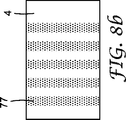
係合突起の造形領域は、連続ウェブである基材層上に設けられてよい。係合突起の前記領域は、連続ウェブの表面上に複数の領域として、例えば、係合突起を有する領域の反復又は非反復パターンで存在し、係合突起を有しない(又は、本明細書で論じているように、係合突起が低密度で存在する、若しくは寸法、高さ、色、アスペクト比等のような何らかの特性が異なる係合突起を有する)領域で部分的に又は完全に取り囲まれている可能性がある。係合突起77が基材フィルム4上に形成することができる様々な潜在的な形を、図8a〜8dに例示する。係合突起を有する造形領域は、係合突起がない(又は上述のように、異なる係合突起を有する)隣接部分の内部に離散領域として存在していてもよく、あるいは係合突起は、係合突起が全く散りばめられていない(若しくはほとんど散りばめられていないか、又は異なる係合突起が散りばめられている)領域を有する隣接部分に存在していてもよい。
The modeling area | region of an engagement protrusion may be provided on the base material layer which is a continuous web. The areas of engaging protrusions are present as a plurality of areas on the surface of the continuous web, for example, in a repeating or non-repeating pattern of areas having engaging protrusions, and no engaging protrusions (or as used herein) As discussed, the engagement protrusions are present at a low density or have engagement protrusions that have different characteristics such as dimensions, height, color, aspect ratio, etc.) partially or completely surrounded There is a possibility. Various potential shapes that the
係合突起領域又は部分は、多種多様な機能を果たすことができる。大前提は、支持体(基材)上の、存在が望まれる領域のみに、1組以上の係合突起を提供することである。係合突起のかかる領域は、接着性、コスト、装飾効果若しくは視覚効果、又は他の何らかの要因に関して効果を発揮する場合がある。一例は、物品上の、所定の望ましい位置でのフック含有領域(ストリップ、矩形、又は要求通りの形)の配置である。これは、フィルム等の裏材上に均質なフック材料を作製し、このフック材料の離散性部分を切り分けて、それを、締結機能性が望まれる物品に(例えば、おむつのサイドパネル、耳部、又はバックシートとして用いるための材料のシートの上へ)接合することによって、慣例上実行される。これは、典型的に、接着剤又は溶融接合を用いて実行される。この最新の方法は、係合突起の領域を、所望の物品上に所望の大きさ及び位置で直接形成することができる。例えば、係合突起は、おむつのサイドパネル、耳部、又はバックシート等として用いることが意図される、連続ウェブ上の所望の領域に配置されてよく、そこから、係合突起を有する個々の部分を(例えば、打抜きによって)取り出して、おむつのサイドパネル、耳部、又はバックシート等を形成することができる。 The engagement protrusion region or portion can perform a wide variety of functions. The main premise is to provide one or more sets of engagement protrusions only in the region where the presence is desired on the support (substrate). Such areas of engaging protrusions may be effective with respect to adhesion, cost, decorative or visual effects, or some other factor. An example is the placement of hook-containing areas (strips, rectangles or shapes as required) at predetermined desired locations on the article. This creates a homogeneous hook material on a backing such as a film, cuts the discrete portions of the hook material and turns it into an article where fastening functionality is desired (eg, diaper side panels, ears). Or onto a sheet of material for use as a backsheet). This is typically performed using an adhesive or melt bonding. This state-of-the-art method can form the area of the engaging protrusion directly on the desired article with the desired size and position. For example, the engagement protrusions may be placed in any desired area on the continuous web intended for use as a diaper side panel, ear, or backsheet, etc. The portion can be removed (eg, by stamping) to form a diaper side panel, ears, backsheet, or the like.
独特な又は新規な機械的性能を付与できるように、係合突起の領域を提供することも可能である。例えば、係合突起は、係合突起を有しない領域、又は低密度(すなわち、基材フィルムの単位面積当たりの係合突起の数)の係合突起を有する領域、又はより大きな若しくはより小さな係合突起を有する領域等によって分離される、領域の形態(例えば、ストリップ類)で存在することもできる。かかる構成は、例えば剥離特性又はせん断特性において、良好な又は仕様通りの特性を提供する場合がある。例えば、せん断特性又は剥離特性の低い領域の間に、せん断特性又は剥離特性の高い領域を割り込ませることができ、これは、ファスナーをループ状の支持体から外すときに更に一様な性能を付与するのに役立つ場合がある。あるいは、より低密度の係合突起を有する領域(係合突起を全く含まない領域もまた包含される)は、例えば、おむつのクロージャーとして使用する際に、フィンガーリフト領域として役立つ場合がある。係合突起を多段プロセスで領域に適用する場合、その領域は、全体的に又は幾分重ねることができ、それによって、既存の予備成形突起の上へ予備成形突起を付着することによって生じる、幾らかの「積み重ねられた」突起をもたらすこともできる。積み重ねられた突起の存在と量はまた、所望の係合特性を達成するように調節することも可能である。 It is also possible to provide a region of engagement protrusions so that unique or novel mechanical performance can be imparted. For example, the engagement protrusion may be a region having no engagement protrusion, a region having engagement protrusions of low density (ie, the number of engagement protrusions per unit area of the base film), or a larger or smaller engagement. It can also exist in the form of regions (eg, strips) separated by regions having mating projections or the like. Such a configuration may provide good or specification properties, for example in peel or shear properties. For example, an area with high shear or peel characteristics can be interrupted between areas with low shear or peel characteristics, which provides more uniform performance when the fastener is removed from the looped support. May be useful to you. Alternatively, regions with lower density engaging projections (including regions that do not include any engaging projections) may also serve as finger lift regions, for example when used as a diaper closure. When engaging projections are applied to an area in a multi-step process, the area can be entirely or somewhat overlapped, resulting in some of the resulting from depositing the preformed protrusion over the existing preformed protrusion. It is also possible to produce such “stacked” protrusions. The presence and amount of stacked protrusions can also be adjusted to achieve the desired engagement characteristics.
係合突起の領域はまた、新規で独特な視覚効果又は装飾的効果を付与できるように提供することもできる。係合突起は、図9aに例示されるような、視認可能な画像又は形、例えば、物体、文字等を形成できるように形を成す領域に提供することができる。複数の形は、更に複雑な画像若しくは形を作り出すために提供されるか、又は単純なパターンで繰り返すことも可能である。これらの視覚効果は、係合突起を1色以上の色で提供することによって(着色材料等を用いることにより)、又は反射性添加物を使用すること等によって高めることができる。 The area of the engagement protrusion can also be provided so as to provide a new and unique visual or decorative effect. Engaging protrusions can be provided in areas that are shaped so that visible images or shapes, such as objects, characters, etc., can be formed, as illustrated in FIG. 9a. Multiple shapes can be provided to create more complex images or shapes, or can be repeated in a simple pattern. These visual effects can be enhanced by providing the engaging protrusions in one or more colors (by using a coloring material or the like), by using a reflective additive, or the like.
独特の視覚効果又は装飾的効果を提供する1つの別法の実施形態は、係合突起を、図形要素が予め印刷された基材上に設けることである。(予め印刷された図形要素は、基材層が透明か否かに応じて、基材層の上面又は下面に存在させることができる。)係合突起の領域は、予め印刷された図形要素と併用して、図形要素として使用することもできる。例えば、基材層に視覚的な画像又は風景(例えば、庭)を予め印刷することができ、そしてその後、係合突起領域を花の形で配置することができる。形成された係合要素領域は、予め印刷された視覚的画像内に無作為に配置されてよい。あるいは、形成された係合要素領域は、例えば図9bに示すように、予め印刷された視覚的画像内の所定の位置に配置されてもよく、図9bでは、形成された係合突起領域77が基材フィルム4上の予め印刷された視覚的画像78内に配置されている。係合突起はまた、所定の領域に背景を構成するように提供することもできる(例えば、係合突起は、風景場面では個々の雪片のように見える可能性がある)。
One alternative embodiment that provides a unique visual or decorative effect is to provide engaging protrusions on a substrate pre-printed with graphic elements. (The preprinted graphic element can be present on the upper surface or the lower surface of the base material layer depending on whether the base material layer is transparent.) The area of the engaging protrusion is the same as the preprinted graphic element. In combination, it can also be used as a graphic element. For example, a visual image or landscape (eg, a garden) can be pre-printed on the substrate layer, and then the engagement protrusion areas can be placed in the form of flowers. The formed engagement element regions may be randomly placed in a pre-printed visual image. Alternatively, the formed engagement element region may be located at a predetermined position in a pre-printed visual image, for example as shown in FIG. 9b. In FIG. 9b, the formed
係合突起は、予め印刷された基材の表面に予備成形突起を配置することによって設けられる。予備成形突起は、画像が形成されていない(すなわち、インク、顔料、金属化コーティングなどを有しない)部分に配置されてもよい。別の方法としては、予備成形突起は、画像形成層がそこに予備成形突起を思い通りに接合できるようなものであれば、画像形成部分に配置することも可能である。あるいは、画像形成層が十分に薄ければ、予備成形突起をその下の基材前面に、画像形成層を介して、画像形成層を変形、融解、あるいは転置することによって融着することができる場合もある。 The engaging protrusions are provided by placing preformed protrusions on the surface of a preprinted substrate. The preform projections may be placed in areas where no image is formed (ie, no ink, pigment, metallized coating, etc.). Alternatively, the preform projections can be placed in the image-forming portion as long as the image-forming layer allows the preform projections to be joined as desired. Alternatively, if the image forming layer is sufficiently thin, the preforming protrusion can be fused to the front surface of the underlying substrate by deforming, melting, or transposing the image forming layer via the image forming layer. In some cases.
記載したように、係合突起を形成するのに使用されるポリマー粒子は、特定の視覚的目的のために、着色する、染める、色素を有すること等が可能である。複数の領域に、特定の視覚効果のために、異なる色の係合突起又は異なる密度若しくは大きさの係合突起を設けることもできる。 As described, the polymer particles used to form the engagement protrusions can be colored, dyed, have pigments, etc. for specific visual purposes. Multiple areas may be provided with different colored engagement protrusions or different density or size engagement protrusions for specific visual effects.
本発明はまた、接着剤、好ましくは感圧接着剤(PSA)を使用することも包含する。かかるPSAとしては、当該技術分野において既知の多種多様な材料、例えば、天然ゴム接着剤、ブロックコポリマー系PSA(例えば、テキサス州ヒューストン(Houston)のクレイトン・ポリマーズ(Kraton Polymers)から入手可能なエラストマー系のもの)、アクリレート系PSA、及びシリコーン系PSAが挙げられる。PSAは、ポリオレフィン系熱可塑性材料(例えば、ポリプロピレン、ポリエチレン、並びにこれらのコポリマー及びブレンド)と十分に接合できるように選択されてよく、例えば、3Mカンパニー(3M Company)から取引表記LSE(例えば、LSE 300)として入手可能なPSAの群を挙げることができる。他の好適な組成物は、シリコーン−ポリ尿素系の感圧接着剤系であり得る。かかる組成物は、例えば、米国特許第5,461,134号及び米国特許第6,007,914号に記載されている。 The invention also encompasses the use of an adhesive, preferably a pressure sensitive adhesive (PSA). Such PSAs include a wide variety of materials known in the art, such as natural rubber adhesives, block copolymer based PSAs (eg, elastomeric systems available from Kraton Polymers, Houston, Texas). Acrylate-based PSA, and silicone-based PSA. The PSA may be selected such that it can be satisfactorily bonded to polyolefin-based thermoplastic materials (eg, polypropylene, polyethylene, and copolymers and blends thereof), such as the trade designation LSE (eg, LSE from 3M Company). 300) can be mentioned as a group of available PSA. Another suitable composition may be a silicone-polyurea based pressure sensitive adhesive system. Such compositions are described, for example, in US Pat. No. 5,461,134 and US Pat. No. 6,007,914.
一実施形態では、PSAは、係合突起を有する領域と隣接する部分に設けられてもよい。PSA領域と係合突起領域のうちいずれか一方又はそれら両方が、別個の領域又は連続した領域として存在してもよい。例えば、図10には、係合突起の移動方向の筋92と隣接する、PSAの移動方向の筋91とが描かれている。
In one embodiment, the PSA may be provided in a portion adjacent to the region having the engaging protrusion. Either one or both of the PSA region and the engagement protrusion region may exist as separate regions or continuous regions. For example, FIG. 10 shows a
本発明の方法で使用される基材は、いずれかの好適な連続性の又は不連続性の基材ウェブ、例えば、多孔質の又は多孔性ではないポリマーフィルム、ラミネートフィルム、不織布ウェブ、紙ウェブ、金属フィルム及び金属箔、等であり得る。基材は、あらゆる既知の方法、例えば、印刷、エンボス加工、フレーム処理、ラミネート加工、粒子コーティング、又は着色すること等によって変性することができる。基材として使用されるポリマーフィルムは、配向又は非配向であり得る。以降に記載する方法を併用して、予備成形突起と接合する能力が変化する部分を基材フィルムが有するように、基材フィルムを設けることもでき、これは、別個の形やパターン等で存在する係合突起領域を支持体に提供する更に別の方法である。基材フィルム表面は、滑らかであり得るか、あるいはリップストップ、引裂き線、又は他の特徴として使用することが可能な、基材に成形された突起若しくは谷部分等の特徴を設けることもでき、これらは基材の前面又は裏面に設けることができる。 The substrate used in the method of the present invention can be any suitable continuous or discontinuous substrate web, such as a porous or non-porous polymer film, laminate film, nonwoven web, paper web. , Metal film and metal foil, and the like. The substrate can be modified by any known method, such as printing, embossing, framing, laminating, particle coating, or coloring. The polymer film used as the substrate can be oriented or non-oriented. In combination with the method described below, the base film can also be provided so that the base film has a portion where the ability to join the preform projection changes, which is present in a separate shape or pattern. This is yet another method for providing an engaging projection region to the support. The substrate film surface can be smooth or can be provided with features such as protrusions or valleys molded into the substrate that can be used as ripstops, tear lines, or other features, These can be provided on the front surface or the back surface of the substrate.
例えば、基材の表面は、例えば、予め散布してそこに固定された粒子を用いて粗面化することも可能である。粒子は、突起の少なくとも末端部を粒子から形成することができるように、基材4に導いて固定する必要がある。突起は、前記粒子をこれ以上変性せずに、完全に粒子からなることもある。粒子を(滑らかな又は粗面化された)前面に導いて固定することについては、いくつかの方法、例えば、先に引用したPCT国際公開特許WO 01133989には無作為な散布及び接着が教示されており、前記特許の開示内容全てを参照によって本明細書に組み込む。
For example, the surface of the base material can be roughened by using, for example, particles previously dispersed and fixed thereto. The particles need to be guided and fixed to the
「粒子」という語は、本明細書で使用するとき、例えば、粒剤、ペレット、粉末、及び液滴を包含する、固体、液体、又は半液体の粒子を指す。適切な粒子は、本明細書中の考察に基づいて選択することができる。粒子の静電付着に依存する(本明細書において以降に記載するような)本発明の実施形態を用いる場合、粒子は、この方法と適合できるように選択する必要がある。静電付着では、粒子は、(基材の選択された領域に、又は基材のどの領域にも一様にのいずれかで)基材に付着できるように、電界の影響を受けて移動する。そのため、この場合、粒子は、電荷を付与され易いはずである(そうでなければ、それらは電界の影響下で移動できない)。かかる方法は当該技術分野では周知であり、かかる粒子の選択は容易である。 The term “particle” as used herein refers to solid, liquid, or semi-liquid particles, including, for example, granules, pellets, powders, and droplets. Appropriate particles can be selected based on the considerations herein. When using embodiments of the invention that rely on electrostatic adhesion of particles (as described herein below), the particles must be selected to be compatible with this method. In electroadhesion, particles move under the influence of an electric field so that they can adhere to a substrate (either on a selected area of the substrate or uniformly on any area of the substrate). . Thus, in this case, the particles should be easily charged (otherwise they cannot move under the influence of an electric field). Such methods are well known in the art and the selection of such particles is easy.
粒子から形成される係合突起の特性の観点から、上面又は上面エッジから基材の前面にある付着端部へ向かって厳密に先細になっている側面図に少なくとも幾らかの係合突起が提供されれば、好ましい。本明細書で使用するとき、側面図とは、基材の前面と直交する図を表す。厳密に先細になるとは、係合突起が基材に近づくにつれて、この突起がより幅狭となることを意味している。例えば、円筒形は、厳密に先細になった形ではない。この種の先細りは、係合した繊維が基材の前面からずれた非先細部分で受け止められなければ、せん断荷重をファスナーに加えたときに前記繊維を基材の前面の方へ引き倒してしまうであろう。したがって、係合突起上でのトルクは最小限であることから、基材を更に脆弱にすることができ、すなわち、更に安価にする、更に可撓性にする、更に皮膚に優しくする、更に薄くすること等が可能である。更に、ファスナーは、突起の上部によって形成される比較的大きな表面積を有し、これがファスナーの手触りを滑らかにする一方で、基材に連結された、比較的小さな総表面積の突起の付着端部をも有して、ファスナーの可撓性と皮膚への優しさを高める場合がある。係合突起はまた、係合上部の面積の周囲と係合突起の高さとの比で特徴付けることもでき、それは一般には1.1〜50まで、好ましくは1.2〜20までである。係合突起はまた、一般に、張り出し周縁部100をも形成するが、これは一般に、上面の面積と付着端部の面積とに差がある。 In view of the properties of the engagement protrusions formed from the particles, at least some engagement protrusions are provided in a side view that is strictly tapered from the top surface or top edge toward the attachment end on the front surface of the substrate. If so, it is preferable. As used herein, a side view represents a view orthogonal to the front surface of a substrate. Strictly tapering means that the protrusion becomes narrower as the engaging protrusion approaches the substrate. For example, a cylindrical shape is not a strictly tapered shape. This type of tapering causes the fibers to pull down toward the front surface of the substrate when a shear load is applied to the fastener unless the engaged fibers are received by the non-tapered portion offset from the front surface of the substrate. Will. Thus, the torque on the engagement protrusion is minimal, which can make the substrate more brittle, i.e. cheaper, more flexible, more skin-friendly, thinner It is possible to do. In addition, the fastener has a relatively large surface area formed by the top of the protrusion, which smooths the feel of the fastener, while the attached end of the relatively small total surface area protrusion connected to the substrate. May also increase the flexibility and tenderness of the fastener. The engagement protrusion can also be characterized by the ratio of the area around the engagement top to the height of the engagement protrusion, which is generally from 1.1 to 50, preferably from 1.2 to 20. The engaging protrusions also generally form an overhanging peripheral edge 100, which generally has a difference in the area of the top surface and the area of the attached end.
本発明の方法に使用される材料から転じて、予め定められた形の本発明による係合突起を用いてファスナー雄部材を製造する好ましい一般的な一連の方法は、以下の基本工程、
前面を有する基材を供給する工程と、
ポリマー材料の粒子を供給する工程と、
好適な表面エネルギーの造形用の接触剥離面を提供する工程と、
前記接触剥離面上に複数のポリマー粒子を分散させる工程と、
前記ポリマー粒子を好適な粘度の少なくとも半液体状態又は軟化状態に至らせるか又はその状態にし、前記剥離面上に配置して、前記剥離面から対応する末端部の方へ突き出ている予備成形突起(予備成形突起は、係合端部において最終的な係合突起の形に少なくともある程度まで予備成形された突起を表す。)を提供する工程と、を含む。予備成形突起は、接触剥離面と接触しているそれらのエッジに沿って接触角度を形成するが、この接触角度は、ポリマー粒子の表面エネルギーと接触剥離面の表面エネルギーに左右される。ポリマー粒子は、接触剥離面と接触しているそのエッジの少なくとも一部で鋭角の接触角度を成すように、好適な期間にわたって半液体状態で維持される。
A preferred general series of manufacturing fastener male members using a predetermined form of engaging projection according to the present invention, turning from the material used in the method of the present invention, includes the following basic steps:
Supplying a substrate having a front surface;
Supplying particles of polymer material;
Providing a contact release surface for shaping of suitable surface energy;
Dispersing a plurality of polymer particles on the contact release surface;
A preformed projection that causes the polymer particles to reach or be in at least a semi-liquid state or a softened state with a suitable viscosity and is disposed on the release surface and projecting from the release surface toward the corresponding end portion (The preform projection represents a projection preformed at least to some extent in the shape of the final engagement projection at the engagement end). The preform projections form a contact angle along their edges that are in contact with the contact release surface, which depends on the surface energy of the polymer particles and the surface energy of the contact release surface. The polymer particles are maintained in a semi-liquid state for a suitable period of time so as to form an acute contact angle at at least a portion of their edges that are in contact with the contact release surface.
次に、予備成形突起は、接触剥離面によって形成されたエッジの形を本質的に維持しながら、基材の前面を、少なくとも一部の予備成形突起の末端部と接触させて固定するために、少なくとも部分的に固体化することができる。 Next, the preforming protrusion is used to fix the front surface of the substrate in contact with the end of at least some of the preforming protrusions while essentially maintaining the shape of the edge formed by the contact release surface. Can be at least partially solidified.
その後、予備成形突起を更に、予備成形突起を接触剥離面から分離して移動するのに十分に固体化することによって基材に付着した係合突起が形成される。これら形成された係合突起は、基材の前面から平坦な上部の方へ突き出ており、その上部は接触剥離面上に形成されていた。平坦な上部は、基材に少なくとも部分的に張り出して周縁部を形成しており、鋭角な接触角度の影響を受ける角度を有するエッジによって少なくとも部分的に縁取られている。 Thereafter, the pre-formed protrusion is further solidified sufficiently to separate and move the pre-formed protrusion from the contact release surface, thereby forming an engaging protrusion attached to the substrate. These formed engaging protrusions protrude from the front surface of the base material toward the flat upper portion, and the upper portion is formed on the contact peeling surface. The flat top extends at least partially over the substrate to form a peripheral edge and is at least partially bordered by an edge having an angle that is affected by an acute contact angle.
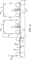
前述のように、予め定められた形の係合突起を形成することができる、2つの包括的なサブセットの方法がある。第1のサブセットの方法では、ポリマー粒子を接触剥離面に、形成すべき形を画定する予め定められたパターンで付着させる。粒子を接触剥離面に、様々な方法によって、選択されたパターン又は形で分配する。最初の方法では、粒子は、形成すべき形を画定する切抜き部分を持ったマスクに対向して突き出している。マスクは所定の位置に固定することができ、その結果、マスクの切抜き部分を通過する粒子が、ストリップ内の(移動している)接触剥離面上に予備成形突起として配置されることとなる。この方法によって(予備成形突起を基材フィルムへ移動させると)もたらされる代表的な係合突起部分の構成を、図8aに示す。粒子の付着は、断続的な移動方向の筋がもたらされるように、停止及び開始することができる。あるいは、マスクは、接触剥離表面と共に、接触剥離面とほぼ同じ速度で移動することができる。この場合、マスクのカットアウト部分を通過する粒子は、接触剥離面上に、切抜き部分で画定された形で付着する。この方法によってもたらされるいくつかの代表的な係合突起部分の構成を、図8b、8c、及び8dに示す。マスクは、使い捨てフィルム、例えば、適切に成形された切抜き部を有するプラスチックフィルムを含むことができる。好ましい実施形態では、マスクは、(図2aの実施形態に関して以下で論じられるような)エンドレスベルトを含む。 As mentioned above, there are two comprehensive subset methods that can form a predetermined shape of the engagement protrusion. In the first subset of methods, the polymer particles are deposited on the contact release surface in a predetermined pattern that defines the shape to be formed. The particles are distributed on the contact release surface in a selected pattern or form by various methods. In the first method, the particles protrude opposite the mask with cutouts that define the shape to be formed. The mask can be fixed in place so that particles that pass through the cut-out portion of the mask are placed as preform projections on the (moving) contact release surface in the strip. A typical engagement protrusion configuration resulting from this method (when the preform protrusion is moved to the substrate film) is shown in FIG. 8a. Particle attachment can be stopped and started so as to provide intermittent movement direction streaks. Alternatively, the mask can move with the contact release surface at approximately the same speed as the contact release surface. In this case, the particles that pass through the cut-out portion of the mask adhere on the contact release surface in the form defined by the cut-out portion. Some representative engagement protrusion configurations resulting from this method are shown in FIGS. 8b, 8c, and 8d. The mask can include a disposable film, such as a plastic film with a suitably shaped cutout. In a preferred embodiment, the mask includes an endless belt (as discussed below with respect to the embodiment of FIG. 2a).
粒子は、様々な手段のうちいずれかによって、マスク上に又はマスクから突き出ている。第一に、重力を用いて、粒子をマスク上に単に落下させることができる。ただし、この方法は、マスクの非切抜き部分に付いた粒子の除去方法に問題がある。これら粒子は、真空、接触除去、又はエアジェット等によって取り除くことができるが、これら粒子のうち一部が後になってマスクの開口部から、粒子を有することが意図されていない部分に落下するか、又は粒子を有することが意図される領域に不適切なタイミングで落下するという可能性が残っている。 The particles protrude onto or from the mask by any of a variety of means. First, using gravity, the particles can simply be dropped onto the mask. However, this method has a problem in the method of removing particles attached to the non-cutout portion of the mask. These particles can be removed by vacuum, contact removal, air jet, etc., but some of these particles will later fall from the mask opening to a part that is not intended to have particles. Or the possibility of falling at an improper timing into an area intended to have particles.
粒子をマスク上に又はマスクを通じて導く別の方法は、静電付着である。この方法では、ポリマー粒子は、静電駆動力によってマスクの方へ導かれる。これは、それらの間に電界を確立できるように2つの電極を提供することによって実行される。第1の電極は、マスクがこの第1の電極と接触剥離面との間にあるように、配置される。第2の電極は、接触剥離面の裏側に配置される。それらの間に電界が確立できるように、電極に電圧を加える。好適な粒子を第1の電極とマスクとの間の隙間へ入れると、粒子は方向転換して、その後、電界の影響を受けて第2の電極の方向へ進む。こうして、粒子は、マスクに衝突し、その結果、いくつかはマスクの中実部分に当たるが、いくつかは切抜き領域を通過して、集合して所望の形を形成するように接触剥離面に付着する。 Another method of directing particles onto or through the mask is electroadhesion. In this method, the polymer particles are directed toward the mask by electrostatic driving force. This is done by providing two electrodes so that an electric field can be established between them. The first electrode is positioned such that the mask is between the first electrode and the contact release surface. The second electrode is disposed on the back side of the contact release surface. A voltage is applied to the electrodes so that an electric field can be established between them. When a suitable particle is placed in the gap between the first electrode and the mask, the particle is redirected and then travels in the direction of the second electrode under the influence of the electric field. Thus, the particles collide with the mask, resulting in some hitting the solid part of the mask, but some passing through the cutout region and adhering to the contact release surface to assemble to form the desired shape. To do.
静電付着は最も有利には、第2の電極を第1の電極の上方に配置した、垂直な配置で実行される。この配置では、粒子は重力に逆らって上向きに進むため、マスクに当たった粒子は下向きに落ちて回収及び/又はリサイクルすることができ、又はそうでなければ、接触剥離面上へ偶然に落下することはほとんどなく、マスクや接触剥離面の裏側に存在している。この方法はまた、粒子の接触剥離面上への更に一様な分布をもたらすという利点も有する。粒子はいずれも、同等に帯電されて、お互いに反発している。このことは、粒子を均一に分配させ続けること、及び個々の粒子に、多数の統合した予備成形突起を形成させないことに役立つ。この方法は、予備成形突起に形成すべき粒子を一様に分布することにより、全体として、粒子を別個の領域内か又は接触剥離面上のいずれかに一様に分配することに有利である。 Electroadhesion is most advantageously performed in a vertical configuration with the second electrode positioned above the first electrode. In this arrangement, the particles travel upwards against gravity, so that the particles that hit the mask can fall down and be collected and / or recycled, or else accidentally fall onto the contact release surface There is almost nothing, and it exists behind the mask and the contact peeling surface. This method also has the advantage of providing a more uniform distribution of the particles on the contact release surface. All particles are equally charged and repel each other. This helps to keep the particles evenly distributed and not to allow the individual particles to form a large number of integrated preform projections. This method is advantageous in that it distributes the particles uniformly in either separate areas or on the contact release surface as a whole by uniformly distributing the particles to be formed on the preform projections. .
本明細書において先に述べたように、マスクは、固定されていても、接触剥離面と共に縦に並んで移動させてもよい。(後者の実施形態は、図2aの実施形態と関して、後で詳細に論じる。)マスキング材料は、それが静電コーティングに適合するように適切に選択すべきである。理想的には、マスク材料は、マスクに当たった粒子が静電引力によってマスクに付着しないようなものである。 As stated earlier in this specification, the mask may be fixed or moved side by side with the contact release surface. (The latter embodiment will be discussed in detail later with respect to the embodiment of FIG. 2a.) The masking material should be appropriately selected so that it is compatible with the electrostatic coating. Ideally, the mask material is such that particles that hit the mask do not adhere to the mask due to electrostatic attraction.
ポリマー粒子もまた、それらが静電コーティングに適合するように選択しなければならない。主要な要件は、与えられた電界の影響によって粒子が、電界によって十分な力が粒子に加わって粒子が2つの電極間を移動するほど十分な誘導電荷を発生させることである。好ましくは、前述の垂直配置を使用することができるように、電気力によって重力を抑えるべきである。幸運にも、予備成形突起を形成するのに適切な材料(すなわち、ポリプロピレン等のような熱可塑性粉末)は大抵、誘電材料(すなわち、電界内に置くと電荷を誘導させることができるもの)である。予備成形突起を形成するのに好適な粒子はまた、一般に小さく、低密度(要するに、重量が軽い)であり、それらは静電力によって重力に逆らって上方へ進み易い。 Polymer particles must also be selected such that they are compatible with the electrostatic coating. The main requirement is that the effect of the applied electric field causes the particle to generate sufficient induced charge such that the electric field exerts sufficient force on the particle to move the particle between the two electrodes. Preferably, gravity should be suppressed by electrical force so that the aforementioned vertical arrangement can be used. Fortunately, materials suitable for forming preform projections (ie, thermoplastic powders such as polypropylene) are often dielectric materials (ie, those that can induce charge when placed in an electric field). is there. The particles suitable for forming the preform projections are also generally small and of low density (in short, light weight), and they tend to travel upward against gravity due to electrostatic forces.
静電性個別付着の代替の実施形態は、模様付き導電性ベルトの形態の第2の電極を利用する。かかる模様付きのベルトは、剥離面と共に縦に並んで動いている接触剥離面の裏側に(垂直配置の場合、剥離面の上方に)配置されており、その結果、粒子は、その裏側に前記模様付き電極の中実部分を有する前記剥離面の領域内で主に接触剥離面に向かって移動することとなる。これにより、粒子供給源と接触剥離面との間に物理的なマスクを挿入する必要がなくなる。かかる模様付きのベルトは、最も都合の良いことに、そこに設けられた穴を有する連続金属ベルトの形態を成しており、電源に接続して、エンドレスループで移動している間でも所望の電圧を維持することができる。(かかる実施形態は、図5aの実施形態に関してより詳細に論じる。)この配置は、予備成形突起を、それらの間に別個の空領域を設けた隣接するパターンで付着するのに最も適している。予備成形突起を、隣接する空領域で囲まれた別個の領域に設けることが望ましい場合、導電性領域がその上に設けられた非導電性ベルト(例えば、その上にスクリーン印刷された導電性インク部分を有する、非導電性ポリマーフィルム)を利用することも可能である。導電性部分の間に電気接触を設けることも、当然、必要であり、それは導電性材料の極めて薄い線を用いて行うことができる。 An alternative embodiment of electrostatic discrete deposition utilizes a second electrode in the form of a patterned conductive belt. Such a patterned belt is disposed on the back side of the contact release surface that is moving vertically along with the release surface (in the vertical arrangement, above the release surface), so that the particles are on the back side of the contact release surface. In the region of the peeling surface having the solid portion of the patterned electrode, the electrode moves mainly toward the contact peeling surface. This eliminates the need to insert a physical mask between the particle supply source and the contact release surface. Such a patterned belt is most conveniently in the form of a continuous metal belt with holes provided therein and connected to a power source, even while moving in an endless loop. The voltage can be maintained. (Such embodiments are discussed in more detail with respect to the embodiment of FIG. 5a.) This arrangement is most suitable for attaching preformed projections in adjacent patterns with separate empty areas therebetween. . If it is desirable to provide the preform projection in a separate area surrounded by adjacent empty areas, a non-conductive belt with conductive areas provided thereon (eg, conductive ink screen printed thereon) It is also possible to utilize a non-conductive polymer film) having a portion. It is of course also necessary to provide electrical contact between the conductive parts, which can be done with very thin lines of conductive material.
前述のように、粒子は、第1の電極とマスク(存在する場合)との間の空間に入れる。あるいは、マスクがない場合、粒子は、第1の電極と接触剥離面との間の空間に入れる。粒子は、それらを電界の影響下に入れて接触剥離面に向かって進めるどのような方法であれ、隙間に入れる必要がある。理論的に、これは一定の基準に基づく方法で実行する。粒子は、当該技術分野において周知の方法で隙間に噴射させても、落下させても、吹き付けても、あるいは注入してもよい。前記の垂直配置では、粒子は噴射によって隙間に横から注入されてもよい。あるいは、粒子は、その上面に粒子を有するキャリアベルトであって、加えた電界によって粒子が接触剥離面に向かって自在に移動できるように隙間に入り込むキャリアベルトを用いて、隙間に導くことも可能である。 As described above, the particles are placed in the space between the first electrode and the mask (if present). Alternatively, in the absence of a mask, the particles enter the space between the first electrode and the contact release surface. The particles need to be in the gap in whatever way they are placed under the influence of an electric field and advanced towards the contact release surface. Theoretically, this is done in a manner based on certain criteria. The particles may be injected into the gap, dropped, sprayed, or injected by methods well known in the art. In said vertical arrangement, the particles may be injected from the side into the gap by jetting. Alternatively, the particles can be guided to the gap by using a carrier belt having particles on its upper surface and entering the gap so that the particles can move freely toward the contact peeling surface by an applied electric field. It is.
前記静電付着や重力補助付着以外の他の方法も利用可能である。粒子を予め定められた形又はパターンで接触剥離面に選択的に導く代替の方法としては、粒子を強制気流、機械的投射、又は搬送等によってマスクに衝突させることが挙げられる。 Other methods than the electrostatic adhesion and gravity assisted adhesion can also be used. An alternative method of selectively directing the particles to the contact release surface in a predetermined shape or pattern is to cause the particles to impinge on the mask, such as by forced air flow, mechanical projection, or transport.
これら第1の包括的なサブセットの方法は、粒子を予備成形突起として多段階で付着させるのに適している。すなわち、特徴(例えば、色、大きさ、アスペクト比、弾性率、等)が多少異なる係合突起を含む、異なる別個の領域を提供することが有利である場合がある。かかる製品を提供するかかる方法の1つは、基材フィルムを加工して、1組の係合突起を付着した後、前記フィルムを別の加工工程に送って、2組目を付着することである。ただし、これは、フィルム支持体の面倒な取り扱いを伴う場合がある。好ましい方法は、複数の付着ステーションを有する加工ラインを提供することである。すなわち、ある定められた組の予備成形突起を接触剥離面に付着した後、別の組の予備成形突起を付着することが可能である。2組目は、(離れた)別個の領域に付着させてもよく、又は接触剥離面全体に(結果として、当然、幾分「積み重ねられた」)突起を付着させてもよい。かかる配置は、移動している接触剥離面が一方のステーションを通過した後、他方のステーションを通過するように、連続して配置された2箇所の付着ステーションを有する加工ラインを用いて提供してもよい。付着ステーションを通過した後、予備成形突起を(同一の)基材フィルムに移動させる。(この一例は、図3aの実施形態を参照して更に詳細に論じる。)代替の配置では、1組目の予備成形突起を、接触剥離面に付着させた後、基材フィルムへ移動させ、次に、2組目の予備成形突起の付着と後続の固定のために二番目の付着ステーションに供給する。 These first comprehensive subset methods are suitable for depositing particles in multiple stages as preform projections. That is, it may be advantageous to provide different distinct regions that include engaging protrusions that have slightly different characteristics (eg, color, size, aspect ratio, modulus, etc.). One such method of providing such a product is to process a substrate film and attach a set of engaging projections, then send the film to another processing step to attach a second set. is there. However, this may involve troublesome handling of the film support. A preferred method is to provide a processing line with multiple deposition stations. That is, it is possible to attach another set of preformed projections after attaching a predetermined set of preformed projections to the contact release surface. The second set may be attached to a separate area (distant), or the protrusions may be attached to the entire contact release surface (as a result, of course “somewhat stacked”). Such an arrangement is provided using a processing line having two deposition stations arranged in succession so that the moving contact release surface passes through one station and then passes through the other station. Also good. After passing the deposition station, the preform projection is moved to the (identical) substrate film. (An example of this will be discussed in more detail with reference to the embodiment of FIG. 3a.) In an alternative arrangement, a first set of preformed protrusions is attached to the contact release surface and then moved to the substrate film, The second set of preform projections is then fed to a second deposition station for subsequent fixation.
第2の包括的なサブセットの方法では、ポリマー粒子を、接触剥離面に付着して、同じ形にすることができる。係合突起の予め定められたパターン又は形は、接触剥離面上のポリマー粒子を、基材の所定の領域に選択的に移動させて付着することによってもたらされる。この選択的な付着は、基材の所定の領域に、予備成形突起ポリマーの接合を多かれ少なかれ受け入れさせることによって実行することが可能である。2つの基本的な方法が存在する。1つ目は、予備成形突起を形成するのに用いられるポリマー粒子との接合力がほとんどないか又は全くない基材フィルムを提供し、そしてその後、更に接合力の高い領域を基材フィルムの表面に付与することである。PSA等の接着剤を使用して予備成形突起を基材に接合する際、基材上の選択された領域のみに(パターンコーティング、ストライプコーティング等によって)PSAを設けるのは容易である。融着(すなわち、溶融接合)の場合、異なるポリマー材料は互いに上手く接合されない場合がある。一例として、例えば、ポリスチレン製の予備成形突起をポリプロピレン製の基材フィルム上に配置すると(あるいは逆もまた同様)、接合形成がほとんど又は全く生じない場合がある。ただし、ポリプロピレン製基材フィルムの選択部分に相溶化層を配置すれば、強い接合が達成される場合がある。かかる相溶化層は、パターンコーティング、スクリーン印刷、蒸気コーティング、プラズマコーティング、光リソグラフィー法、化学蒸着等を包含する当該技術分野の多種多様な方法によって、模様付きの又は別個の又は不連続な様式で基材に適用することができる。 In a second comprehensive subset of methods, the polymer particles can be deposited on the contact release surface and have the same shape. The predetermined pattern or shape of the engagement protrusion is provided by selectively moving and attaching the polymer particles on the contact release surface to a predetermined region of the substrate. This selective deposition can be performed by allowing a predetermined area of the substrate to accept more or less the joining of the preformed projection polymer. There are two basic methods. The first provides a substrate film that has little or no bonding force with the polymer particles used to form the preform projections, and then provides a region of higher bonding force on the surface of the substrate film. It is to give to. When bonding preform projections to a substrate using an adhesive such as PSA, it is easy to provide PSA only in selected areas (by pattern coating, stripe coating, etc.) on the substrate. In the case of fusion (ie, melt bonding), different polymer materials may not be successfully bonded together. As an example, for example, when a preformed projection made of polystyrene is placed on a polypropylene substrate film (or vice versa), little or no joint formation may occur. However, if a compatibilizing layer is disposed on a selected portion of the polypropylene base film, strong bonding may be achieved. Such compatibilizing layers can be applied in a patterned or separate or discontinuous manner by a variety of methods in the art including pattern coating, screen printing, vapor coating, plasma coating, photolithography, chemical vapor deposition, and the like. It can be applied to a substrate.
相溶化層は、当該技術分野で利用可能な、広く知られた結合層及び接着層のうちいずれかを含んでいてよい。必要なのは、相溶性結合層が、基材との十分な接着性、及び予備成形突起を形成するのに用いられるポリマー粒子との十分な接着性を有することだけである。この方法では、ポリマー粒子と基材フィルムはもはや、厳密に同じ材料から、又は組成が極めて近いか若しくは似する材料から形成する必要がない場合がある。これにより、基材とポリマー粒子とを、互いに最も望ましい物理特性に基づいて選択することができる。例えば、極めて柔軟で可撓性の基材フィルムと、極めて硬く剛性のポリマー粒子を選択すること(又は逆もまた同様)が望ましい場合がある。これは、基材フィルム上に相溶化層を用いることによって実行可能である。この方法の一例は、図6aの実施形態に関して後で論じる。 The compatibilizing layer may include any of the well known bonding and adhesive layers available in the art. All that is required is that the compatible tie layer has sufficient adhesion to the substrate and sufficient adhesion to the polymer particles used to form the preform projections. In this method, the polymer particles and the substrate film may no longer need to be formed from exactly the same material or from materials that are very close or similar in composition. This allows the substrate and polymer particles to be selected based on the most desirable physical properties of each other. For example, it may be desirable to select a very soft and flexible substrate film and extremely hard and rigid polymer particles (or vice versa). This can be done by using a compatibilizing layer on the substrate film. An example of this method is discussed later with respect to the embodiment of FIG.
他の方法は、互いに十分に接合する基材とポリマー粒子とを使用することと、マスキング層を基材の選択された領域に適用することである。一実施形態では、マスキング層は、基材層上で保持されかつポリマー粒子と接合しない、恒久的な層である。かかるマスキング層は、例えば、ポリマー(例えば、シリコーン、フルオロシリコーン、若しくはパラレン(Paralene)等のコーティング)、又は金属若しくは金属酸化物であり得る。必要なのは、前記層が粒子と上手く接合しないこと又はそれを介して生じる接着性を許容するほど十分に置換できないことだけである。かかる層は、パターンコーティング、スクリーン印刷、蒸気コーティング、プラズマコーティング、光リソグラフィー法、化学蒸着等を包含する当該技術分野の多種多様な方法によって、模様付き又は別個の又は不連続な様式で基材に適用することができる。表面上の至る所にマスキング層を付着することや、それを選択された部分でエッチング、アブレーション等によって除去することも可能である。 Another method is to use a substrate and polymer particles that are sufficiently bonded together and to apply a masking layer to selected areas of the substrate. In one embodiment, the masking layer is a permanent layer that is retained on the substrate layer and does not bond to the polymer particles. Such a masking layer can be, for example, a polymer (eg, a coating such as silicone, fluorosilicone, or Paralene), or a metal or metal oxide. All that is required is that the layer does not bond well with the particles or cannot be replaced sufficiently to allow the adhesion produced therethrough. Such layers can be applied to the substrate in a patterned or separate or discontinuous manner by a wide variety of methods in the art including pattern coating, screen printing, vapor coating, plasma coating, photolithographic methods, chemical vapor deposition and the like. Can be applied. It is also possible to apply a masking layer everywhere on the surface, or to remove it by etching, ablation, etc. at selected portions.
別の実施形態では、マスキング層は、前記剥離面からの移動中にポリマー粒子を基材と接触させないために物理的バリアを特定の位置に構成することができるように、一時的に設けられる。この場合、マスキング層は、図7aの実施形態を参照して後で説明するように、一時的に用いられるが最終製品の一部にはならないフィルムであってよい。 In another embodiment, the masking layer is temporarily provided so that the physical barrier can be configured at a specific location to prevent the polymer particles from contacting the substrate during movement from the release surface. In this case, the masking layer may be a film that is used temporarily but not part of the final product, as will be described later with reference to the embodiment of FIG. 7a.
表面エネルギー、表面張力、及び濡れの分野に精通する当業者は、粒子にとって好適なポリマーと、好適な表面エネルギーの接触剥離面との組み合わせを選択すること及び更には、接触剥離面を好適な時間内濡らす接触剥離面の温度において好適な粘度を有する粒子を選択することもできる。接触剥離面の表面エネルギーは、シリコーン処理された表面、フッ素性化学物質、コロナ放電、又はフレーミングなどの既知の材料及び方法によって作り出してよい。接触剥離面は、使用される半液体化及び固体化した特定のポリマー粒子を解放できなければならない。特定の剥離面は、特定のポリマーを解放することはできるが、他のポリマーを解放することはできないことが知られている。例えば、ポリエチレン製の剥離面は、好適なポリプロピレン粒子を解放することができるが、特定のポリエチレン粒子は互いに溶着又は融着する傾向があるため、解放することができない。「解放」という語は、本明細書で使用するとき、粒子又は予備成形突起の材料の(容認できない)損傷又は損失を伴わずに、粒子が接触剥離面から引き離される現象を指す。 Those skilled in the field of surface energy, surface tension, and wetting will select a combination of a suitable polymer for the particles and a contact release surface of a suitable surface energy and, moreover, the contact release surface for a suitable time. It is also possible to select particles having a suitable viscosity at the temperature of the contact release surface that is wetted internally. The surface energy of the contact release surface may be created by known materials and methods such as silicone treated surfaces, fluorinated chemicals, corona discharge, or framing. The contact release surface must be able to release the particular polymer particles that are semi-liquefied and solidified. It is known that certain release surfaces can release certain polymers but not other polymers. For example, a polyethylene release surface can release suitable polypropylene particles, but cannot release certain polyethylene particles because they tend to weld or fuse together. The term “release” as used herein refers to the phenomenon in which particles are pulled away from the contact release surface without (unacceptable) damage or loss of the material of the particles or preformed protrusions.
粒子を接触剥離面上に重力によって分散させることは、任意の好適な方法で、例えば、粒子を散布装置で散布することによって実行することができる。他の方法は本明細書に記載している。粒子は、それらが予備成形突起を形成するように単位表面積当たりの速度で分散されるべきであり、1つの粒子は1つの予備成形突起を形成することができるが、上述のように融合してもよい。粒子は、接触剥離面上に粒子を分散させる前、その間、及び/又はその後で、少なくとも半液体状態にすることができる。「少なくとも半液体」とは、液体又は半液体を意味する。好適な融解方法は、選択されたポリマーの特性に依存し、例えば、加熱、希釈化、溶解、乳化、分散、等を挙げることができる。 Dispersing the particles by gravity on the contact release surface can be carried out in any suitable manner, for example by spreading the particles with a spreading device. Other methods are described herein. The particles should be dispersed at a rate per unit surface area so that they form preformed protrusions, and one particle can form one preformed protrusion, but fused as described above Also good. The particles can be in at least a semi-liquid state before, during and / or after dispersing the particles on the contact release surface. “At least semi-liquid” means a liquid or semi-liquid. Suitable melting methods depend on the properties of the selected polymer and can include, for example, heating, dilution, dissolution, emulsification, dispersion, and the like.
接触剥離面上の予備成形突起を基材の前面と接触させて固定するのに好適な固体性(固体化の度合い又は程度)は、特定の状況に応じて当業者によって決定することができる。それは通常、予備成形突起が接触剥離面上に形成された状態よりも固体性の高い状態を意味するが、必ずしも必要ではない。好ましくは予備成形突起は、基材の前面と接触している間、その形状を少なくとも部分的に維持するのに十分な固体性を有するべきである。それは通常、予備成形突起の少なくとも最小自由高さと更には予備成形突起の好適なエッジ角度とを維持することを主に意味する。予備成形突起における必要な固体性の設定は、材料依存性であって、冷却、乾燥、加熱、架橋、硬化、化学処理等を挙げることができる。好適な固体性の予備成形突起は、接触剥離面上に配置されており、基材の前面が予備成形突起の末端部と接触してそこに固定することができるように、基材の前面で覆うことができる。末端部は、接触剥離面から最も離れた端部である。予備成形突起に基材の前面と接触させる前に、予備成形突起に付着するであろう、更に追加の分散粒子などを供給又は補給することができる。基材の前面は、予備成形突起が半液体状態である場合に、予備成形突起と接触させることができる。この場合、接触の後及び最終的な固体化の前に、予備成形突起を伸張することによって幾分長くすることができるが、予備成形突起を前記剥離面から取り外すことによって、予備成形突起の中央部をより細くすることも可能である。当業者はまた、一様ではないと思われる高さの予備成形突起と接触させることができるほど十分に可撓性の基材を選択することもできる。基材の前面は、滑らかであることができるが、それはまた、適当に粗くすることもでき、例えば、基材上に予め散布されて固定された粒子又は突起を用いて粗面化することも可能である。予備成形突起の末端部を基材の前面に固定することは、例えば、追加した接着剤(例えば、感圧接着剤、ホットメルト接着剤、又はUV硬化接着剤)での接着、紫外線照射による架橋によって達成可能であり、あるいは接触している材料(基材の前面又は予備成形突起)の固有の接着性又は融着を利用することも可能である。融着による固定は、本明細書において後で詳細に論じる。固定中に、自由な張り出し部又は周縁部、及び予備成形突起の実際の高さが十分に保たれるように注意すべきである。例えば、突起を基材の前面に過度に押し込むこと又は圧縮することは避けるべきである。前記剥離面からの分離と除去との双方に好適な、予備成形突起及び基材の適切な固体性は、特定の状況に応じて当業者によって決定することができる。予備成形突起の固体性は、それらを前記剥離面から取り外すときには、必ずしもそうではないが、通常は、それらを基材の前面に最初に接触させたときよりも硬い状態である。好ましくは、予備成形突起は、前記剥離面からの分離中に、その形状を少なくとも部分的に維持するのに十分な固体性を有しているべきである。それは通常、主として、好適な全体的形状を、特に、形成されたエッジ角度と関連して維持することを意味するが、基材の前面との好適に強固な結合を保つこともまた重要な要因である。基材は一般に、その形を維持して剥離面から予備成形突起を分離するのに十分な固体性を有しているべきである。形成されたときのままの平坦な上面は、滑らかであり得るが、当該技術分野で既知のように、幾分か粗面化することもでき、例えば、サンドペーパー状であるか又は溝付きであることも可能である。上面構造は、主として接触剥離面によって決定され、真の幾何学的な意味では本来平面的でなくても、本質的には平坦である。ただし、上面を本質的には平坦でないようにする後処理、例えば、非接触の熱処理を使用することもある。小さな多数の突起が有利な場合、この方法では、別個の予備成形突起のうちの少なくとも一部が、予備成形突起1つ当たり厳密には1つのポリマー粒子を含んでいれば、好ましい。 The solidity (degree or degree of solidification) suitable for fixing the preformed protrusions on the contact release surface in contact with the front surface of the substrate can be determined by one skilled in the art depending on the particular situation. That usually means a state of higher solidity than the state in which the preform projections are formed on the contact release surface, but this is not always necessary. Preferably, the preform protrusion should have sufficient solidity to at least partially maintain its shape while in contact with the front surface of the substrate. It usually means mainly to maintain at least the minimum free height of the preform projection and also the preferred edge angle of the preform projection. The necessary solidity setting in the preform projection is material-dependent and can include cooling, drying, heating, crosslinking, curing, chemical treatment, and the like. A suitable solid preform projection is disposed on the contact release surface and is provided on the front surface of the substrate so that the front surface of the substrate can contact and be secured to the end of the preform projection. Can be covered. The end portion is the end portion farthest from the contact release surface. Prior to contacting the preform projection with the front surface of the substrate, additional dispersed particles or the like that will adhere to the preform projection can be supplied or replenished. The front surface of the substrate can be brought into contact with the preform projection when the preform projection is in a semi-liquid state. In this case, after contact and before final solidification, it can be somewhat lengthened by stretching the preform projection, but by removing the preform projection from the release surface, the center of the preform projection It is also possible to make the part thinner. One skilled in the art can also select a substrate that is sufficiently flexible that it can be brought into contact with a pre-projection of a height that appears to be non-uniform. The front surface of the substrate can be smooth, but it can also be suitably roughened, for example, roughened with particles or protrusions that have been pre-spread and fixed on the substrate. Is possible. Fixing the end of the preformed protrusion to the front surface of the substrate can be achieved by, for example, bonding with an added adhesive (eg, pressure sensitive adhesive, hot melt adhesive, or UV curable adhesive), or crosslinking by UV irradiation. It is also possible to take advantage of the inherent adhesion or fusion of the material in contact (front surface of the substrate or preformed protrusion). Fusion fixation is discussed in detail later in this specification. Care should be taken that the free overhang or rim and the actual height of the preform projections are kept sufficiently during fixation. For example, excessive pushing or compression of the protrusions on the front surface of the substrate should be avoided. The appropriate solidity of the preform projections and the substrate, suitable for both separation and removal from the release surface, can be determined by one skilled in the art depending on the particular situation. The solidity of the preform projections is not necessarily when they are removed from the release surface, but is usually harder than when they are first contacted with the front surface of the substrate. Preferably, the preform projection should have sufficient solidity to at least partially maintain its shape during separation from the release surface. It usually means mainly maintaining a favorable overall shape, especially in relation to the edge angle formed, but maintaining a suitably strong bond with the front surface of the substrate is also an important factor It is. The substrate should generally have sufficient solidity to maintain its shape and separate the preform projections from the release surface. The flat top surface as formed can be smooth, but can also be somewhat roughened as known in the art, e.g., sandpaper-like or grooved. It is also possible. The top structure is primarily determined by the contact release surface and is essentially flat, even if it is not inherently planar in the true geometric sense. However, post-treatments that make the top surface essentially non-flat, such as non-contact heat treatment, may be used. Where a large number of small protrusions are advantageous, this method is preferred if at least some of the separate preformed protrusions contain exactly one polymer particle per preformed protrusion.
前記方法では、少なくとも一部の予備成形突起が接触角度10°〜85°、好ましくは30°〜80°で提供されれば、好ましい。これは、大抵の個々の予備成形突起に関する接触角度範囲である。好ましい実施形態では、この範囲が、予備成形突起における平均の接触角度となる。 In the method, it is preferred if at least some of the preformed protrusions are provided at a contact angle of 10 ° to 85 °, preferably 30 ° to 80 °. This is the contact angle range for most individual preform projections. In a preferred embodiment, this range is the average contact angle at the preform projection.
この方法では、少なくとも一部の係合突起に、その各側面図において係合突起が平坦な上部又は上部エッジから基材の前面へと厳密に先細となる(好ましくは、厳密に凸状となる)輪郭が与えられれば、好ましい。これは通常、この方法によって極めて容易に達成され、好適な表面上に置かれた水滴のように、半レンズ状の予備成形突起が典型的に作り出される。前記方法では、非熱可塑性及び熱可塑性のポリマー粒子を使用することができ、その選択は、必要な強度、求められる表面エネルギー、コスト等に基づく。しかし、前記方法では、ポリマー粒子が熱可塑性ポリマーであれば、好ましい。 In this method, at least a portion of the engaging protrusions, in each side view, the engaging protrusions are strictly tapered from the flat upper or upper edge to the front surface of the substrate (preferably strictly convex) ) It is preferable if a contour is given. This is usually accomplished very easily by this method, typically creating a semi-lens shaped preform projection, such as a water drop placed on a suitable surface. The method can use non-thermoplastic and thermoplastic polymer particles, the selection of which is based on the required strength, the required surface energy, cost, and the like. However, in the above method, it is preferable if the polymer particles are thermoplastic polymers.
液体の滴が固体の剥離面上に付着する場合、及びこの剥離面の表面エネルギーがその液体の表面エネルギー(又は表面張力)よりも幾分高い場合、液体は典型的には、接触角度ゼロで固体を完全に濡らす。液体の場合、各「固体−液体」対は0°〜180°の接触角度を有し、その接触角度によって、液体の滴が固体をほぼ濡らす。半液状、例えば軟化した熱可塑性樹脂製の粒子の場合、接触角度を成すプロセスは、時間と温度の現象である。高い表面エネルギーの固体剥離面の場合、液体ポリマーは、十分な時間を与えれば完全に濡れる。この高い表面エネルギーの固体の剥離面を高温に維持して、低温の固体粒子をその上に置くと、接触角度が初期の鈍角から最終的にゼロの接触角度へと時間の経過と共に変化するプロセスが始まる。この変化プロセスを、例えば、好適な冷却で遮断することにより、任意の所望の接触角度を達成することができる。そのため、高い表面エネルギーの固体の接触剥離面は、本発明のプロセスでは有用である。しかしながら、剥離面の表面エネルギーが高くなるにつれて、最後に剥離面を予備成形突起から分離し難くなる。更に、接触剥離面の表面エネルギーがポリマー粒子の表面エネルギーに比べて高すぎると、操作者が無意識に間違う機会が多くなって、接触剥離面を過度に濡らす予備成形突起を形成する。接触剥離面の表面エネルギーが第1の表面エネルギー(粒子の表面エネルギー)プラス60mJ/m2ほど高くなければ、接触剥離面を過剰に濡らす危険が低くなる。 If a drop of liquid is deposited on a solid release surface, and if the surface energy of this release surface is somewhat higher than the surface energy (or surface tension) of the liquid, the liquid typically has a contact angle of zero. Wet solid completely. In the case of liquids, each “solid-liquid” pair has a contact angle between 0 ° and 180 °, which causes the liquid drop to substantially wet the solid. In the case of semi-liquid, eg softened thermoplastic particles, the process of forming the contact angle is a phenomenon of time and temperature. In the case of a high surface energy solid release surface, the liquid polymer will be completely wetted if sufficient time is allowed. A process in which the contact angle changes over time from an initial obtuse angle to finally a zero contact angle when this high surface energy solid release surface is maintained at a high temperature and low temperature solid particles are placed on it. Begins. Any desired contact angle can be achieved, for example, by shutting off this changing process with suitable cooling. Therefore, a high surface energy solid contact release surface is useful in the process of the present invention. However, as the surface energy of the release surface increases, it becomes difficult to finally separate the release surface from the preform projection. Furthermore, if the surface energy of the contact release surface is too high compared to the surface energy of the polymer particles, there are many opportunities for the operator to unintentionally make mistakes, forming preformed protrusions that wet the contact release surface excessively. If the surface energy of the contact release surface is not as high as the first surface energy (particle surface energy) plus 60 mJ / m 2 , the risk of excessive wetting of the contact release surface is reduced.
高い表面エネルギーの接触剥離面はまた、係合突起のエッジ角度を過度に鋭角にして、過度に薄く及び後の使用中に場合によっては破断する可能性のある周縁部を作り出して、望ましくない汚染を生じさせる。より大きな接触角度又はエッジ角度を許容して、薄く脆弱なエッジ及び周縁部を形成する係合突起に対する高い保護を付与することが、時にはより妥当となる場合がある。そのため、前記方法が、表面エネルギーが第1の表面エネルギー(粒子の表面エネルギー)よりも低い接触剥離面を提供することを含めると、好ましいことがある。この場合、製品におけるエッジ角度は、オンラインの操作パラメータによってではなく、材料の選択によって決定され得る。更に、接触剥離面の表面エネルギーが低くなるにつれて、最後に予備成形突起をそこから分離し易くなる。しかしながら、予備成形突起を接触剥離面から分離するのに必要な一定の力は、有益な可能性もある。一部の予備成形突起は、基材の前面に弱く固定されることがある。つまり、この固定強度は、意図される最終用途に望まれるよりも低く、その結果、係合突起が、場合によって使用中に破断して剥がれることがある。これは、欠陥検出が困難である。その結果、接触剥離面の表面エネルギーが第1の表面エネルギー(粒子の表面エネルギー)マイナス23mJ/m2よりも高ければ、好ましい。このレベルの接触剥離面を用いると、予備成形突起を接触剥離面から分離するための分離力は、基材の前面に弱く固定された突起を取り外すのに十分高く、それによって、オンラインでの故障検出及び訂正機構が提供される場合がある。 The high surface energy contact release surface also makes the edge angle of the engagement protrusions too sharp, creating a peripheral edge that is too thin and can possibly break during subsequent use, causing unwanted contamination. Give rise to It may sometimes be more reasonable to allow greater contact angles or edge angles to provide higher protection against engaging protrusions that form thin and fragile edges and perimeters. Thus, it may be preferred that the method includes providing a contact release surface whose surface energy is lower than the first surface energy (particle surface energy). In this case, the edge angle in the product can be determined by material selection rather than by online operating parameters. Furthermore, as the surface energy of the contact release surface decreases, it becomes easier to finally separate the preform projections therefrom. However, the constant force required to separate the preform projections from the contact release surface can be beneficial. Some preform protrusions may be weakly secured to the front surface of the substrate. That is, this fixed strength is lower than desired for the intended end use, and as a result, the engagement protrusions can sometimes break and peel off during use. This is difficult to detect defects. As a result, it is preferable if the surface energy of the contact release surface is higher than the first surface energy (particle surface energy) minus 23 mJ / m 2 . With this level of contact release surface, the separation force to separate the preform projections from the contact release surface is high enough to remove the projections that are weakly secured to the front surface of the substrate, thereby reducing online failure A detection and correction mechanism may be provided.
熱可塑性の予備成形突起(全体を通して突出部と呼ぶこともある)に関する本明細書の前述の方法において、基材の前面と少なくとも一部の予備成形突起の末端部との固定が熱による固定又は融着を含むのであれば、好ましい。 In the foregoing method of the present specification relating to thermoplastic preform projections (sometimes referred to as projections throughout), the fixing of the front surface of the substrate and the end of at least some of the preform projections is a thermal fixation or If fusion is included, it is preferable.
熱による固定には、予備成形突起又は基材の前面のうちいずれか一方を、材料や圧力等に応じて溶融することを挙げることができる。好ましくは、予備成形突起と基材の前面の両方を潜在的に溶融させることによって融着する。融着は、予備成形突起を基材の前面に熱によって固定することである。この場合、予備成形突起は、剥離面による下方からの鮮鋭化と、被覆、及び融着による上方からの基材との固定との両方に上手く適した粒子から構成されている。粒子は、融着中、接触角度を好適に形成するのに十分に融解しなければならないが、エッジ角度を維持できるのに十分に固体性を維持しなければならない。熱可塑性ポリマー粒子は、選択されたポリマーに適切な条件で、10分間当たりl〜90グラムのメルトフローレートを有することが好ましい。 Fixing by heat can include melting either one of the preformed protrusion or the front surface of the base material according to the material, pressure, or the like. Preferably, both the preform projections and the front surface of the substrate are fused by potentially melting. Fusion is the fixing of the preform projections to the front surface of the substrate by heat. In this case, the preformed projections are composed of particles that are well suited for both sharpening from below by the release surface and fixing to the substrate from above by coating and fusion. During fusing, the particles must melt sufficiently to suitably form the contact angle, but must remain solid enough to maintain the edge angle. The thermoplastic polymer particles preferably have a melt flow rate of 1 to 90 grams per 10 minutes at conditions appropriate for the selected polymer.
前記方法の後続工程において、熱による固定は、接触剥離面をポリマー粒子又は予備成形突起の軟化温度よりも低い温度に維持する一方で、基材の前面を少なくとも一部の予備成形突起の付着端部と接触させることを含む。基材の裏面は、好ましくは、高温の気体にさらすことによって加熱される。ただし、放射又はIR熱等の他の加熱方法を用いてもよい。加熱された気体を用いる場合、加熱した基材の裏面でのガス圧は、典型的に、加熱された基材の前面での圧力(例えば、ガス圧)よりも高く、それによって加熱された基材を少なくとも一部の予備成形突起の末端部に対して押圧して、基材へのその固定を増強させる。この圧力差は、例えば、接触剥離面又は基材の前面の真下から減圧を施すことによって高めることもできる。 In subsequent steps of the method, the thermal fixation maintains the contact release surface at a temperature lower than the softening temperature of the polymer particles or preform projections, while the front surface of the substrate is attached to at least some of the preform projections. Including contacting the part. The back side of the substrate is preferably heated by exposure to a hot gas. However, other heating methods such as radiation or IR heat may be used. When using a heated gas, the gas pressure at the back side of the heated substrate is typically higher than the pressure at the front side of the heated substrate (eg, gas pressure), thereby heating the heated substrate. The material is pressed against the end of at least some of the preform projections to enhance its fixation to the substrate. This pressure difference can be increased, for example, by applying a reduced pressure directly below the contact release surface or the front surface of the substrate.
更に、これらの方法では、下向きに曲げて下部の予備成形突起に届くことが可能な、十分に柔軟性のある基材が供給されれば、予備成形突起が高さの異なるものであるかどうかは大きな問題ではない。基材全体が熱可塑性であり、実際に軟化されて、それによって柔軟で可撓性になって、加熱時に容易に曲がるかあるいは更に伸張するのであれば、特に有用である。(これは、特に、前述のように、高さの異なる予備成形突起の領域が存在する場合に、有利となる場合がある。)所望により、基材は、完全に軟化されることができる。ここで、完全に軟化するとは、すべての構成要素やその層(例えば、複合基材の場合)を軟化温度より高い温度で軟化することを意味する。 In addition, these methods can determine if the preform projections are of different heights if a sufficiently flexible substrate is provided that can be bent down and reach the lower preform projections. Is not a big problem. It is particularly useful if the entire substrate is thermoplastic and is actually softened, thereby becoming soft and flexible and easily bends or stretches when heated. (This may be advantageous, especially when there are regions of preformed protrusions of different heights as described above.) If desired, the substrate can be completely softened. Here, completely softening means softening all the constituent elements and their layers (for example, in the case of a composite substrate) at a temperature higher than the softening temperature.
基材を剥離面から分離した後、一部の予備成形突起は、基材に固定されず、接触剥離面に留まる場合がある。これらは通常、非常に小さな残留ポリマー粒子であって、後から分散される粒子と融解して、取り去られる場合がある。接触剥離面からのそれらの除去を規則的に提供することにより、前記プロセスを更に均一にして、安定化させることが可能である。したがって、前記方法が、
複数のポリマー粒子を接触剥離面に分散する前に、以下の工程、
接触剥離面を、ポリマー粒子の軟化温度及び基材の前面の軟化温度のいずれよりも高い温度まで加熱する工程と、
基材の前面を、加熱した接触剥離面と接触させることにより、前面を軟化する工程と、
軟化した前面を、加熱した接触剥離面に対して好適に押し当てて、それによってポリマー粒子汚染残留物を基材の前面に融着させる工程と、
接触剥離面と基材に、接触剥離面から基材を分離するのに適した温度を付与する工程と、
基材を前記剥離面から分離し、それによって接触剥離面をクリーニングする工程と、を更に含むのであれば好ましい。
After separating the substrate from the release surface, some preformed protrusions are not fixed to the substrate and may remain on the contact release surface. These are usually very small residual polymer particles that may be melted away with the later dispersed particles and removed. By regularly providing their removal from the contact release surface, it is possible to make the process more uniform and stable. Thus, the method
Before dispersing a plurality of polymer particles on the contact release surface, the following steps:
Heating the contact release surface to a temperature higher than both the softening temperature of the polymer particles and the softening temperature of the front surface of the substrate;
Softening the front surface by bringing the front surface of the substrate into contact with the heated contact release surface;
Suitably pressing the softened front surface against the heated contact release surface, thereby fusing the polymer particle contamination residue to the front surface of the substrate;
Providing the contact release surface and the substrate with a temperature suitable for separating the substrate from the contact release surface;
It is preferable that the method further includes a step of separating the substrate from the release surface and thereby cleaning the contact release surface.
この方法は、粒子と基材の前面との両方の熱可塑性特性を、接触剥離面のクリーニングに利用している。前記工程中に、少量の残留ポリマー汚染は取り去られて、通常、基材の前面には存在しなくなる。基材は、その後、普段通り利用することができる。例えばロール又はコンベヤーを備える連続操作では、剥離面は、粒子の各分散前に回転毎にクリーニングされ、それ故に、蓄積する接触剥離面汚染を常に低レベルに維持することができる。 This method utilizes the thermoplastic properties of both the particles and the front surface of the substrate to clean the contact release surface. During the process, a small amount of residual polymer contamination is removed and usually no longer exists on the front side of the substrate. The substrate can then be used as usual. In continuous operation, for example with rolls or conveyors, the release surface is cleaned with every rotation before each dispersion of the particles, so that the accumulated contact release surface contamination can always be kept at a low level.
予備成形突起を基材の前面に融着している間、基材は典型的には、前記剥離面の上にあって、予備成形突起によって支えられており、前記突起間の空間を架橋している。基材の前面がその軟化温度を超える場合、その中の任意の分子配向が、シート状の基材の少なくとも前記架橋部分を収縮させることによって、問題を引き起こす場合がある。これは、例えば、収縮耐性のある好適な裏材を有する複合基材を用いることによって、回避することができる。例えば、ポリエステルフィルム又は紙製の裏材と、その上に前面としてコーティングされたポリエチレン層とを含む基材は、その基材に生じ得る収縮に潜在的に耐えることができる。一方、収縮が問題点である場合、予備成形突起又は粒子を融着するときに基材に分子配向がなければ、好ましい。分子配向したフィルムは、基材の前面を、加熱した剥離面(これは、接触剥離面であることもある)と接触させることにより前処理し、それによって基材の前面を本質的に分子配向しないようにすることができる。分子配向が好適に解放されれば、クリーニング工程中に、軟化した基材に接触剥離面を緊密に押圧することで、この前処理工程を実行することも可能である。 While the preform projections are fused to the front surface of the substrate, the substrate is typically on the release surface and supported by the preform projections to bridge the space between the projections. ing. If the front surface of the substrate exceeds its softening temperature, any molecular orientation therein may cause problems by shrinking at least the cross-linked portion of the sheet-like substrate. This can be avoided, for example, by using a composite substrate having a suitable backing that is shrink resistant. For example, a substrate comprising a polyester film or paper backing and a polyethylene layer coated thereon as a front surface can potentially withstand the shrinkage that can occur on the substrate. On the other hand, if shrinkage is a problem, it is preferred if the substrate has no molecular orientation when fusing the preform projections or particles. The molecularly oriented film is pretreated by contacting the front surface of the substrate with a heated release surface (which may be a contact release surface), thereby essentially aligning the front surface of the substrate with molecular orientation. You can avoid it. If the molecular orientation is preferably released, the pretreatment step can be performed by pressing the contact release surface tightly against the softened substrate during the cleaning step.
高圧状態の加熱された気体(好ましくは空気)は、加熱された気体を排出するガスノズルを用いて最も効果的に供給することができる。基材をノズルの出力オリフィスの前方に移動することで、裏面が、排出された高温の気体と接触して、基材が軟化する。同時に、ノズルから排出された高温の気体は、基材の裏面に沿って、典型的には基材の進行方向と平行に、気流を発生させてそれを維持する。ノズルが固定されて、基材が縦方向に移動している場合、高温の気流は、本質的には、縦方向と平行な方向と、縦方向と逆の方向との両方を有する。高温の気流、例えば、高温の空気流は、軟化した基材上で牽引力を出して、基材の裏面を引きずって移動させる。これは、軟化した基材を伸張する傾向がある。気流が速くなるにつれて、この伸張の効果はより強くなる。低スループットの構成の場合、すなわち、高温の気体の速度が遅い場合や、特に厚い基材の場合には、本質的に分子配向しない基材を使用することができる。スループットがより高く、気体流量がより多い場合、特に、より薄い基材を用いると、基材のこの縦方向の伸張が非常に顕著になる可能性があり、これは望ましくないことがある。例えば、基材が長手方向に伸張すると、縦方向では、ファスナーの厚さを制御することが困難となる可能性があるか、又は不特定の長さのロールが生じる可能性がある。更に、伸張は、基材を薄くして引き裂くことによって、偶発的な破損を導く可能性もある。 High pressure heated gas (preferably air) can be supplied most effectively using a gas nozzle that discharges the heated gas. By moving the substrate in front of the output orifice of the nozzle, the back surface comes into contact with the discharged hot gas, and the substrate is softened. At the same time, the hot gas discharged from the nozzle generates and maintains an airflow along the back surface of the substrate, typically parallel to the direction of travel of the substrate. When the nozzle is fixed and the substrate is moving in the longitudinal direction, the hot airflow essentially has both a direction parallel to the longitudinal direction and a direction opposite to the longitudinal direction. A hot air stream, for example, a hot air stream, causes traction on the softened substrate and moves it by dragging the back surface of the substrate. This tends to stretch the softened substrate. As the airflow increases, the effect of this stretching becomes stronger. In the case of a low-throughput configuration, i.e. when the temperature of the hot gas is slow, or in particular with a thick substrate, a substrate that is essentially not molecularly oriented can be used. With higher throughput and higher gas flow rates, especially with thinner substrates, this longitudinal stretching of the substrate can be very significant, which may be undesirable. For example, if the substrate stretches in the longitudinal direction, it may be difficult to control the thickness of the fastener in the longitudinal direction, or rolls of unspecified length may occur. Furthermore, stretching can lead to accidental failure by thinning and tearing the substrate.
伸張の効果は、好適な分子配向を基材内にもたらすことによって相殺することができる。伸張の問題は、基材が縦方向に熱収縮する可能性を備えていれば、解決することができる。気体の熱が基材内の配向を弛緩させ(すなわち、基材を収縮させる傾向があり)、これによって、加熱した気流による伸張が打ち消される。したがって、本発明の変形形態では、加熱した気体を排出するのに適合したガスノズルが1つ以上設けられる。基材の裏面は、基材を1つ以上のガスノズルと相対的に移動させながら、1つ以上のガスノズルによって、排出される加熱された気体と接触させる。基材が移動している方向は縦方向であり、本質的には基材の平面内にある。基材は、好ましくは、縦方向に少なくとも1パーセントの熱収縮性(長手方向の熱収縮性)を有する。熱による固定には、基材をその熱収縮温度よりも高い温度に加熱することが挙げられる。 The effect of stretching can be offset by providing a suitable molecular orientation in the substrate. The problem of stretching can be solved if the substrate has the possibility of heat shrinking in the machine direction. The heat of the gas relaxes the orientation within the substrate (i.e., tends to shrink the substrate), thereby counteracting the stretching due to the heated air stream. Thus, in a variant of the invention, one or more gas nozzles adapted to discharge heated gas are provided. The back surface of the substrate is brought into contact with the heated gas discharged by the one or more gas nozzles while moving the substrate relative to the one or more gas nozzles. The direction in which the substrate is moving is the longitudinal direction and is essentially in the plane of the substrate. The substrate preferably has a heat shrinkability (longitudinal heat shrinkability) of at least 1 percent in the machine direction. Fixing by heat includes heating the substrate to a temperature higher than its heat shrink temperature.
本明細書で使用するとき、ある方向における「熱収縮性」とは、基材の材料等の材料の文脈では、その材料が、材料への熱エネルギーの伝達に応答して、所与の方向又は寸法においてその長さを縮める可能性を意味するものとする。材料の「熱収縮性」はパーセント値であり、所与の方向におけるその収縮前の長さと収縮後の長さとの差を収縮前の長さで除算して100倍したものに等しい。材料の所与の方向における収縮後の長さは、170℃の温度で45秒間のように材料を収縮させた後の、所与の方向における材料の長さを意味する。収縮は、例えば、材料を高温のシリコーン油に浸漬して、自在に収縮させることによって決定することができる。140℃の温度を14秒間使用すると、通常のポリマー材料では本質的にあらゆる収縮が弛緩することが判明した。本明細書で使用するとき、材料の「収縮温度」は、高温に曝露された材料が熱収縮し始める温度を指す。 As used herein, “heat-shrinkable” in a direction refers to a given direction in the context of a material, such as a substrate material, in response to the transfer of thermal energy to the material. Or it shall mean the possibility of shortening its length in dimension. The “heat shrinkability” of a material is a percentage value and is equal to the difference between its pre-shrinkage length and post-shrinkage length in a given direction divided by the pre-shrinkage length multiplied by 100. The post-shrinkage length of a material in a given direction means the length of the material in a given direction after shrinking the material at a temperature of 170 ° C. for 45 seconds. Shrinkage can be determined, for example, by immersing the material in hot silicone oil and allowing it to shrink freely. It has been found that using a temperature of 140 ° C. for 14 seconds relaxes essentially any shrinkage with normal polymer materials. As used herein, the “shrink temperature” of a material refers to the temperature at which a material exposed to high temperatures begins to heat shrink.
本発明のこの変形形態の利点は、排出された高温の気流によって軟化した基材に及ぶ伸張効果を打ち消すのに役立つことである。速い生産速度では、1パーセントを超える長手方向の熱収縮性によって、改善された結果をもたらすことができる。したがって、前記方法のこの変形形態では、長手方向の熱収縮性が少なくとも10パーセント、より好ましくは少なくとも20パーセント、更に好ましくは少なくとも30パーセント、なおより好ましくは少なくとも40パーセント、及びなお更に好ましくは少なくとも50パーセントの基材が、高温の気流によって生じた力と前記生産速度とに応じて接触及び固定のために供給されれば、好ましい。 An advantage of this variant of the invention is that it helps to counteract the stretch effect on the substrate softened by the discharged hot air stream. At high production rates, greater than 1 percent longitudinal heat shrinkability can provide improved results. Thus, in this variation of the method, the longitudinal heat shrinkability is at least 10 percent, more preferably at least 20 percent, even more preferably at least 30 percent, even more preferably at least 40 percent, and even more preferably at least 50 percent. It is preferred if the percent substrate is supplied for contact and fixation depending on the force produced by the hot air stream and the production rate.
横方向の高温の気流によって基材に及ぼされる伸張効果は、幅方向、すなわち、基材の進行経路方向に垂直な方向(それは、機械装置では機械横方向と呼ばれる。)では、あまり重大ではないかあるいは(ノズル配置の詳細に応じて)ほぼゼロである。それ故に、基材が、幅方向に高い熱収縮可能性又は高い熱収縮性を有している場合、基材のエッジは、収縮するか又は狭まることがあり、その結果、高温の気体と接触したときに折畳まれるか又はしわが生じる。これは一般には望ましいものではない。そのため、主方向又は縦方向に垂直な平面内方向における基材の熱収縮性は、ゼロであるか又は長手方向の熱収縮性よりも低ければ、好ましい。「幅方向の熱収縮性がゼロ」には、本明細書で使用するとき、基材が、熱にさらされたときに幅方向において、収縮するのではなく、長さの増加又は伸張を発現する場合が包含される。この熱収縮性の差についての利点は、それが、軟化した基材上の2つの直交する次元において、高温の気流の差異化された牽引効果に対して、差異化された反作用を付与することである。一般に、主方向に垂直な平面内方向(幅方向)での基材の熱収縮性は、50パーセント未満である。好ましくは、幅方向の熱収縮性は、高温の気流によって生じる力と生産速度とに応じて、40パーセント未満、より好ましくは30パーセント未満、更に好ましくは25パーセント未満である。他方で、高温の気体によって加熱された基材は、幅方向の熱膨張を発現して、製品にしわを生じさせる場合がある。これは、適度に低いが確実なレベルの熱収縮性を基材の幅方向に付与することで、相殺することができる。したがって、前記状況では、基材の幅方向の熱収縮性が少なくとも1パーセントであれば、好ましい。 The stretching effect exerted on the substrate by the transverse hot airflow is less significant in the width direction, ie, the direction perpendicular to the direction of travel of the substrate (it is called the cross machine direction in mechanical devices). Or nearly zero (depending on nozzle placement details). Therefore, if the substrate has a high heat shrinkability or high heat shrinkability in the width direction, the edge of the substrate may shrink or narrow, resulting in contact with a hot gas. When folded or wrinkled. This is generally not desirable. Therefore, it is preferable that the heat shrinkability of the base material in the main direction or the in-plane direction perpendicular to the longitudinal direction is zero or lower than the heat shrinkability in the longitudinal direction. “Zero heat shrinkability”, as used herein, indicates that the substrate does not shrink in the width direction when exposed to heat, but increases or stretches in length. The case is included. The advantage of this difference in heat shrinkage is that it gives a differentiated reaction to the differentiated traction effect of the hot air stream in two orthogonal dimensions on the softened substrate. It is. Generally, the heat shrinkability of the substrate in the in-plane direction (width direction) perpendicular to the main direction is less than 50 percent. Preferably, the heat shrinkability in the width direction is less than 40 percent, more preferably less than 30 percent, and even more preferably less than 25 percent, depending on the force and production rate generated by the hot air stream. On the other hand, a substrate heated by a high-temperature gas may develop thermal expansion in the width direction and cause wrinkles in the product. This can be offset by providing a reasonably low but reliable level of heat shrinkability in the width direction of the substrate. Therefore, in the above situation, it is preferable if the heat shrinkability in the width direction of the substrate is at least 1 percent.
本発明の方法は更に、別個の予備成形突起を形成できるように、ポリマー粒子を接触剥離面に分散する工程も包含する。好ましくは、予備成形突起を形成する多数の又は大抵の粒子は、予備成形突起が完成して固体化する前に、隣接する粒子又は予備成形突起に触れないようにするべきである(しかしながら、かかる例は、先に記載した通り、「積み重ねられた」突起を形成するのが望ましいのであれば、好ましい場合がある)。粒子が時期尚早に接触すると、隣接している粒子又は予備成形突起の統合が生じる。ただし、ファスナーでは、係合突起が互いに近接していれば、ファスナーの固定強度は一般に更に強くなる(すなわち、ファスナーはより良好に機能する)。この方法では、粒子の分散、例えば散布が典型的に一過程として履行されるので、突起の近接性は、理論的に可能性のある最大値には通常至らず、すなわち、突起は、最終製品内で互いに僅かに近づく可能性もある。ファスナーが完成した後、その後生じる適度なその熱収縮は、必要に応じて、ファスナー係合突起が相対的に近づくことを改善する可能性がある。しかしながら、この工程を実行するためには、形成されたファスナーの基材が熱収縮性を幾分有しなければならない。そのため、本発明の方法のこの変形形態では、形成されたファスナーの基材が、少なくとも1パーセントの長手方向の残留熱収縮性を有していれば、有利である。好ましくは、形成されたファスナーは、この実施形態では、少なくとも5パーセント、より好ましくは少なくとも10パーセント、更に好ましくは少なくとも15パーセント、なおより好ましくは少なくとも20パーセント、なお更に好ましくは少なくとも25パーセントの長手方向の熱収縮性を有する。この方法では、形成されたファスナーは、その後、少なくとも主方向に熱収縮する。この熱収縮は、形成されたファスナーへの任意の好適な熱エネルギー伝播方法によるが、好ましくは鋭角の接触角度と係合突起の幾何学的特徴とが一般に、本質的には完全に保持されるか又は少なくとも好適に保護されるように起こり得る。好ましくは、熱エネルギーは、ファスナーの基材の裏面から、形成されたファスナーへ伝播する。例えば、これは、高温の材料、例えば、ホットメルト接着剤を基材の裏面に、ファスナーを支持体に固定する一部として付着させることによって実行できる。熱収縮は、隣接する係合突起を、隣接する係合突起の間を雌型ファスナー部分の係合する繊維が通り抜けるのに十分に互いに分離させておけるほど十分に低い程度で維持すべきである。好ましくは、ファスナーの基材は、約0.1〜25パーセント以下まで熱収縮する。 The method of the present invention further includes the step of dispersing the polymer particles on the contact release surface so that separate preform projections can be formed. Preferably, many or most of the particles forming the preform projection should not touch the adjacent particles or preform projection before the preform projection is completed and solidified (however, such a An example may be preferred if it is desirable to form “stacked” protrusions as described above). Premature contact of particles results in the integration of adjacent particles or preform projections. However, in the fastener, if the engaging protrusions are close to each other, the fixing strength of the fastener is generally further increased (that is, the fastener functions better). In this method, particle dispersion, eg, dispersion, is typically performed as a process, so that the proximity of the protrusions usually does not reach the maximum theoretically possible, i.e., the protrusions are the final product. May be slightly closer together. After the fastener is completed, the moderate thermal shrinkage that occurs thereafter may improve the relative engagement of the fastener engagement protrusions as needed. However, in order to perform this process, the formed fastener substrate must have some heat shrinkability. Thus, in this variation of the method of the present invention, it is advantageous if the formed fastener substrate has a residual heat shrinkage of at least 1 percent in the longitudinal direction. Preferably, the formed fastener in this embodiment is at least 5 percent, more preferably at least 10 percent, more preferably at least 15 percent, even more preferably at least 20 percent, and even more preferably at least 25 percent in the longitudinal direction. Heat shrinkability. In this method, the formed fastener is then thermally contracted at least in the main direction. This heat shrinkage is due to any suitable method of thermal energy propagation to the formed fastener, but preferably the acute contact angle and the geometric features of the engaging protrusions are generally completely retained essentially. Or at least to be suitably protected. Preferably, thermal energy propagates from the back surface of the fastener substrate to the formed fastener. For example, this can be done by attaching a hot material, such as a hot melt adhesive, to the backside of the substrate as part of securing the fastener to the support. Thermal shrinkage should be maintained at a sufficiently low degree that adjacent engagement protrusions can be sufficiently separated from each other between adjacent engagement protrusions to allow the engaging fibers of the female fastener portion to pass through. . Preferably, the fastener substrate heat shrinks to about 0.1 to 25 percent or less.
経済的な基材材料、例えば、吹込成形又は注型成形した熱可塑性ポリマーフィルムは、これらフィルムが多くの場合、必要とされるよりも高い熱収縮値を有するので、適当な熱収縮パラメータでは容易に又は経済的に利用できない場合がある。好適な基材は、前処理工程によってこれら経済的な基材材料から製造することができる。前処理は、好適には、その分子配向を完全に収縮させることなく、制御された部分的な弛緩状態で、実質的に熱収縮を低減する。すなわち、熱収縮性の高いフィルムを自在に収縮しないように機械的に保持し、それと同時に、高温で又は軟化した状態に保持すれば、その熱収縮可能性又は熱収縮能力は、材料の長さ又は面積を実際に減少させずに、対応する程度まで経時的に徐々に低下する。したがって、これらの種類の基材材料は、基材材料の前面を予備成形突起と接触させて固定させる前に前処理するのであれば、好ましい。基材の前処理は、前処理剥離面を提供する工程と、
前処理剥離面を、基材の前面の軟化温度よりも高い好適な温度まで加熱する工程と、
基材の前面を前処理剥離面と接触させて、それに押圧することにより、前面を軟化させる工程と、
軟化した前面を、好適な時間、加熱した前処理剥離面と接触したままにする一方で、基材を自由に収縮させないことにより、少なくともその長手方向の熱収縮性を低減する工程と、
前処理剥離面と基材とに、基材を前処理剥離面から分離するのに好適な温度を付与する工程と、
基材を前処理剥離面から分離する工程と、を含む。
Economical base materials, such as blown or cast thermoplastic polymer films, are often easier with appropriate heat shrinkage parameters because these films often have higher heat shrinkage values than required. Or may not be economically available. Suitable substrates can be made from these economical substrate materials by a pretreatment process. The pretreatment preferably substantially reduces thermal shrinkage in a controlled partial relaxation state without fully shrinking its molecular orientation. That is, if a film having high heat shrinkability is mechanically held so as not to shrink freely, and at the same time, kept at a high temperature or in a softened state, its heat shrinkability or heat shrinkability is determined by the length of the material. Alternatively, it gradually decreases over time to a corresponding degree without actually reducing the area. Accordingly, these types of substrate materials are preferred if they are pretreated before the front surface of the substrate material is brought into contact with the pre-formed projections and fixed. The pretreatment of the substrate includes a step of providing a pretreatment release surface;
Heating the pretreatment release surface to a suitable temperature higher than the softening temperature of the front surface of the substrate;
A step of softening the front surface by bringing the front surface of the substrate into contact with the pretreatment peeling surface and pressing it;
Reducing the heat shrinkability of at least its longitudinal direction by leaving the softened front surface in contact with the heated pretreated release surface for a suitable time while not allowing the substrate to shrink freely;
Providing the pretreatment release surface and the substrate with a temperature suitable for separating the substrate from the pretreatment release surface;
Separating the substrate from the pretreatment release surface.
前処理に使用される前記剥離面、すなわち、前処理剥離面は、上述の接触剥離面と類似しているか又は異なっていることがある。前処理剥離面は、基材を適時に適切に解放できなければならない。基材は好ましくは、例えばその標準の寸法を、ただし主としてその長さを維持するために、いかなる収縮をも本質的に回避する。これは、基材の前面を前処理剥離面と完全に接触させ続けることによって実行可能である。この目的のために、基材の軟化した前面と前処理剥離面(例えば、ポリテトラフルオロエチレン表面)との間の粘着性を利用することができる。これを行うためには、前記2つの面の間の残留空気を好ましくは、基材を前処理剥離面に接触させて押圧しながら排除する必要がある。基材の長手方向の熱収縮性が好適な値まで低下する一方で、幅方向の熱収縮率もまた低下する場合がある(好ましくは減少するであろう)。接触時間が長くなり、及び温度が高くなるにつれて、熱収縮性はより大幅に減少する。そして、その逆も同様である。 The release surface used for pretreatment, i.e. the pretreatment release surface, may be similar to or different from the contact release surface described above. The pre-treatment release surface must be able to properly release the substrate in a timely manner. The substrate preferably avoids essentially any shrinkage, for example to maintain its standard dimensions but primarily its length. This can be done by keeping the front surface of the substrate in full contact with the pretreatment release surface. For this purpose, the adhesiveness between the softened front surface of the substrate and the pretreated release surface (eg polytetrafluoroethylene surface) can be utilized. In order to do this, the residual air between the two surfaces should preferably be removed while pressing the substrate against the pretreatment release surface. While the heat shrinkability in the longitudinal direction of the substrate decreases to a suitable value, the heat shrinkage in the width direction may also decrease (preferably will decrease). As the contact time increases and the temperature increases, the heat shrinkage decreases more significantly. And vice versa.
前記プロセスの開始時の基材の長さが、前記プロセス終了時に、前記基材から製造されたファスナー製品の長さとあまり変わらないか又は同等であれば、望ましいことがあり得る。その予測通り、これは、前処理した基材において正しい長さ方向の熱収縮性を設定することに影響され得る。そのため、前処理プロセスでは、前処理された基材の長さが、形成されるファスナーの長さと本質的に同じとなるように、低い値の長手方向の熱収縮性を達成することが可能である。この方法の工程では、低い平衡値は、基材の前処理中に、
剥離面の前処理温度、及び
基材と前処理剥離面との接触期間のうちいずれか一方を調節することによって、継続して維持することができる。
It may be desirable if the length of the substrate at the start of the process is not much different or equivalent to the length of the fastener product made from the substrate at the end of the process. As expected, this can be affected by setting the correct lengthwise heat shrinkability in the pretreated substrate. Therefore, in the pretreatment process, it is possible to achieve a low value of longitudinal heat shrinkage so that the length of the pretreated substrate is essentially the same as the length of the fastener to be formed. is there. In this method step, low equilibrium values are obtained during substrate pretreatment,
It can be continuously maintained by adjusting any one of the pretreatment temperature of the release surface and the contact period between the substrate and the pretreatment release surface.
前処理工程を利用する実行可能な製造手順は、ベルト経路に沿って循環運動を続ける剥離ベルト外表面を有するエンドレス剥離ベルトを利用することと、
基材を前処理するために、ベルト経路の第1の位置にあるベルト外表面の第1の部分を前処理剥離表面として使用することと、
前処理された基材からファスナーを形成するために、前記第1の位置から適当に変位した、ベルト経路の第2の位置にあるベルト外表面の第2の部分を、接触剥離面として使用することと、
基材を連続的な基材フィルムの形態でベルトと同一速度で移動させながら供給して、第1の及び第2の位置でベルト外表面と接触させることである。
A viable manufacturing procedure that utilizes a pre-treatment step utilizes an endless release belt having an outer surface of the release belt that continues to circulate along the belt path;
Using a first portion of the belt outer surface at a first position in the belt path as a pretreatment release surface to pretreat the substrate;
A second portion of the belt outer surface at a second position in the belt path, suitably displaced from the first position, is used as the contact release surface to form a fastener from the pretreated substrate. And
Feeding the substrate in the form of a continuous substrate film at the same speed as the belt and contacting the outer surface of the belt at the first and second positions.
この解決策は、単一の剥離ベルトを、基材を前処理するためとその前処理された基材からファスナーを更に製造するためとに使用することから有益であり、初期基材と最終製品との長さの差、ゼロをもたらすことができる。この長さの差がゼロであることは、2つの異なる目的のために、すなわち、一方では基材を前処理するために、また他方では、粒子を付着させて予備成形突起を形成し、そして前処理された基材をそれらと接触させて固定するために、どの位置でも同じ速度で走行している同一のベルトを上手に活用するのに望ましい。第1の位置での剥離面の速度は、初期の基材の速度と望ましくは同じ速度であり、第2の位置での剥離面の速度は、形成された最終的なファスナー製品と望ましくは同じ速度である。前処理によってもたらされる基材の長手方向の低い値の熱収縮性が平衡値から外れていれば、この区分の基材は、第1のベルト位置と第2のベルト位置との間でベルトと自在に接触する場合に、より短く又はより長くなる傾向がある。このことは、基材フィルム緩衝材に浮動ローラー(単数又は複数)を設けて、その浮動ローラー(単数又は複数)の動きの動向を検出することで、検知することができる。前記2つのベルト位置の間の基材フィルムの自由区分を短くすれば、前処理された基材の長手方向の熱収縮性を低減することができる。また、その逆も同様である。前処理された基材の長手方向の熱収縮性は、第1の位置でのベルトの温度を上昇させること及び/又はベルト外表面の第1の部分を延長させて、それに沿ってベルトと基材とを接触させることよって、基材の前処理期間を延長することにより、更に低減することができる。また、その逆も同様である。この解決策は、剥離ベルトの外表面を、前処理された基材の軟化した熱可塑性の前面を剥離ベルトとベルトの回転毎に接触させることによって、いかなる起こり得るポリマー粒子汚染をも取り除くという、更なる利点を有している。 This solution is beneficial because it uses a single release belt to pretreat the substrate and to further manufacture fasteners from the pretreated substrate, the initial substrate and the final product. The difference between the length and zero can be brought about. This length difference of zero is for two different purposes, namely on the one hand to pre-treat the substrate and on the other hand to deposit the particles to form the preformed projections, and It is desirable to make good use of the same belt running at the same speed at any position to fix the pretreated substrates in contact with them. The speed of the release surface at the first location is preferably the same as the initial substrate speed, and the speed of the release surface at the second location is preferably the same as the final fastener product formed. Is speed. If the low value of heat shrinkage in the longitudinal direction of the substrate caused by the pretreatment is out of equilibrium, then the substrate of this section is between the belt position between the first belt position and the second belt position. When touching freely, it tends to be shorter or longer. This can be detected by providing the base film cushioning material with a floating roller (s) and detecting the movement of the floating roller (s). If the free section of the substrate film between the two belt positions is shortened, the heat shrinkability in the longitudinal direction of the pretreated substrate can be reduced. The reverse is also true. The longitudinal heat shrinkability of the pretreated substrate can increase the temperature of the belt at the first location and / or extend the first portion of the belt outer surface along with the belt and base. Further reduction can be achieved by extending the pretreatment period of the substrate by contacting the material. The reverse is also true. This solution removes any possible polymer particle contamination by bringing the outer surface of the release belt into contact with the softened thermoplastic front surface of the pretreated substrate with each release of the release belt and belt. It has further advantages.
本発明の更なる目的は、前記方法によって容易に実現可能で、対応する利点を有する、新規ファスナー製品を提供することである。 It is a further object of the present invention to provide a new fastener product that can be easily realized by the method and has corresponding advantages.
本発明の製品は、ループ状の布地と係合するためのファスナーであって、シート状の基材が複数の固体の係合突起、好ましくは本質的に固体の又は剛性の係合突起の付いた前面を有する、前記ファスナーである。係合突起は、上端部と付着端部(これは、全体を通して最下部と呼ぶこともある。)とを有する。付着端部は、基材の前面と固定位置で接合している。係合突起と基材の前面とを固定する工程がある場合、基材と係合突起とは、異なる材料又は同じ材料から形成することができる。基材の前面から突き出している少なくとも1つの係合突起は、接触剥離面によって本質的に平坦な頂点を有するように形成されることがある。ただし、一般に上端部は、それが係合突起の付着端部とは異なるように、変形処理が施されてきた。変形表面及び/又は接触剥離面が平坦であれば、上端部は、形成されたまま、それに応じて平坦である。上部はまた、一般には、基材の上に少なくとも部分的に張り出しており、その張り出し部分は、周縁部とも呼ばれる。 The product of the present invention is a fastener for engaging a looped fabric, wherein the sheet-like substrate has a plurality of solid engagement protrusions, preferably essentially solid or rigid engagement protrusions. The fastener has a front surface. The engaging protrusion has an upper end portion and an adhering end portion (this may be referred to as a lowermost portion throughout the entirety). The adhering end is joined to the front surface of the substrate at a fixed position. When there is a step of fixing the engaging protrusion and the front surface of the base material, the base material and the engaging protrusion can be formed of different materials or the same material. The at least one engagement protrusion protruding from the front surface of the substrate may be formed with an essentially flat apex by the contact release surface. However, in general, the upper end portion has been subjected to deformation processing so that it is different from the attached end portion of the engaging protrusion. If the deformed surface and / or the contact release surface is flat, the upper end remains flat as it is formed. The top also generally overhangs at least partially over the substrate, and the overhang is also referred to as the peripheral edge.
形成されたままの係合突起の上部はまた、その上部を縁取る明確なエッジをも有している。係合突起はまた外被表面をも有しており、それは、エッジに沿って上部と交わっており、基材の前面では、係合突起の上部エッジから付着端部の方へ延びている。外被表面と上面とは、一般的にはエッジ全体に沿って鋭角のエッジ角度を成すように近接している。 The upper part of the as-formed engagement projection also has a clear edge that borders the upper part. The engaging projection also has a jacket surface that intersects the top along the edge and extends on the front side of the substrate from the upper edge of the engaging projection toward the attachment end. The outer surface and the upper surface are generally close to each other so as to form an acute edge angle along the entire edge.
使用中に、係合突起は本質的に、基材に固定された固体として働くべきであり、好ましくは可撓性である。本明細書で使用するとき、係合突起の厳密には凸状の輪郭線は、側面図では、外側から見たときは凸状であって、直線ではない。張り出し周縁部の下面又は外被表面に関する厳密には凸状の形は、それが、少なくとも1つの係合突起に比較的大きな厚さをもたらすことから、有益であることが分かった。少なくとも1つの係合突起の少なくとも一つの側面図において、外被表面は、好ましくは、エッジと隣接している少なくともその一部が厳密には凸状である。この凸状の形は、基材に張り出した周縁部のエッジに強度を付与する。凸状の形はまた、係合繊維を基材に向かって下向きに有効に開くことによって、上述のように、係合突起やそれらを付着させる基材の上でのトルク荷重も軽減する。別の好ましい実施形態では、係合突起は、少なくとも1つの係合突起の少なくとも一つの側面図では、その上部から基材の前面に向かって厳密に先細になっている。 During use, the engaging protrusions should essentially act as a solid secured to the substrate and are preferably flexible. As used herein, the strictly convex contour of the engagement protrusion is convex in the side view when viewed from the outside and not a straight line. A strictly convex shape with respect to the underside or jacket surface of the overhanging rim has been found to be beneficial because it provides a relatively large thickness for the at least one engaging projection. In at least one side view of the at least one engaging projection, the jacket surface is preferably strictly convex, at least part of which is adjacent to the edge. This convex shape imparts strength to the edge of the peripheral edge protruding from the substrate. The convex shape also reduces the torque load on the engagement protrusions and the substrate to which they are attached, as described above, by effectively opening the engagement fibers downward toward the substrate. In another preferred embodiment, the engagement protrusion is strictly tapered from the top to the front surface of the substrate in at least one side view of the at least one engagement protrusion.
本発明のファスナーは、望ましい長所を有している。それは、極薄の不織布を包含する低い嵩高性のループ状の布地に、良好なせん断強度を付与することができる。それはまた、あらゆる方向にせん断強度を付与することもでき、それ故に、本質的に等方性である。本発明のファスナーはまた、一般に平坦な上部を有する高密度の小さな突起と、ファスナーを皮膚に優しくする可撓性の基材とを用いて製造することもできる。係合突起を形成する粒子と比べて、基材の選択には大いに柔軟性がある。本発明のファスナーはまた、低コストでもあり得る。 The fastener of the present invention has desirable advantages. It can impart good shear strength to low bulky looped fabrics that include ultra-thin nonwovens. It can also impart shear strength in any direction and is therefore essentially isotropic. The fasteners of the present invention can also be manufactured using a high density of small protrusions with a generally flat top and a flexible substrate that makes the fastener gentle to the skin. The choice of substrate is much more flexible than the particles that form the engaging protrusions. The fasteners of the present invention can also be low cost.
製品の好ましい形態であって、前記方法の好ましい実施形態に対応する形態のうちいくつかは、様々な長所を表すことができる。 Some of the preferred forms of the product, corresponding to the preferred embodiments of the method, can represent various advantages.
第一に、ファスナーは、外被表面の少なくとも一つの側面図において少なくとも1つの係合突起が、側縁部と隣接する少なくとも全ての部分で厳密に凸状であれば、有利である。更に、ファスナーは、外被表面の各側面図において少なくとも1つの係合突起が、側縁部と隣接する少なくとも全ての部分で厳密に凸状であれば、有利である。また、ファスナーは、各側面図において少なくとも1つの係合突起が、その上部から基材の前面に向かって厳密に先細になっていれば、有利でもある。係合突起の外被表面と上面とによって、エッジ角度が画定される。これらエッジ角度は、有利には、エッジ全体に沿っており、15°〜85°、又は30°〜80°の角度を有する。ファスナーは、少なくとも1つの係合突起が外被表面全体の少なくとも一つの側面図において厳密に凸状であれば、更に有利である。これにより、係合する繊維が基材の前面に向かって下向きに有効に開いて、トルク荷重を軽減する。ファスナーが、外被表面全体の各側面図において厳密に凸状の、少なくとも1つの係合突起を含むのであれば、更に有利である。 First, the fastener is advantageous if at least one engaging projection in at least one side view of the jacket surface is strictly convex in at least all the portions adjacent to the side edges. Furthermore, the fastener is advantageous if at least one engaging projection in each side view of the jacket surface is strictly convex in at least all the portions adjacent to the side edges. The fastener is also advantageous if at least one engagement protrusion in each side view is tapered from the upper part toward the front surface of the substrate. The edge angle is defined by the outer surface and the upper surface of the engaging protrusion. These edge angles are advantageously along the whole edge and have an angle of 15 ° to 85 °, or 30 ° to 80 °. The fastener is further advantageous if the at least one engaging projection is strictly convex in at least one side view of the entire jacket surface. As a result, the engaged fibers are effectively opened downward toward the front surface of the base material to reduce the torque load. It is further advantageous if the fastener comprises at least one engaging projection that is strictly convex in each side view of the entire jacket surface.
基材の前面の材料が、少なくとも1つの係合突起の、それらが付着する外被表面の材料と異なる場合もまた有利でもある。かかる配置は、異なる材料から構成された基材フィルム及び予備成形突起を、前述のように、必要に応じて相溶化層と共に利用すれば、達成することができる。基材の前面の材料は、例えば、ショア硬度値の相違で判断される場合、少なくとも1つの係合突起の外被表面の材料よりも軟質であればなお更に有利でもある。 It is also advantageous if the material of the front surface of the substrate is different from the material of the jacket surface to which they attach at least one engaging projection. Such an arrangement can be achieved by using a base film and preformed projections made of different materials together with a compatibilizing layer as necessary, as described above. It is even more advantageous if the material of the front surface of the substrate is softer than the material of the jacket surface of at least one engaging projection, for example, as judged by the difference in Shore hardness value.
一部の用途では、ファスナーの基材が基材の平面内で弾性的に伸縮自在であり、及び少なくとも1つの係合突起の外被表面の材料が弾性的でなければ、有利でもある。基材は、弾性積層体等を包含するエラストマー材料を含むことができる。これは、弾性のファスナー製品を製造することができ、例えば、おむつ及び包装用テープに特に有益であり得る。 For some applications, it is also advantageous if the fastener substrate is elastically stretchable in the plane of the substrate and the material of the jacket surface of the at least one engaging projection is not elastic. The substrate can include an elastomeric material including an elastic laminate or the like. This can produce elastic fastener products and can be particularly beneficial, for example, for diapers and packaging tapes.
加えて、本発明のファスナーはまた、例えば、カーペット又はポリマーシートを床又はタイルに固定するため及び布地を部屋の壁に固定するための自己接着ファスナーテープ等の他の技術分野で使用することも可能である。 In addition, the fasteners of the present invention may also be used in other technical fields such as, for example, self-adhesive fastener tapes for securing carpets or polymer sheets to floors or tiles, and fabrics to room walls. Is possible.
本発明のファスナーは、様々な基材材料の表面上に形成することも可能である。これは、上述のように、フィルムであることができるが、任意の好適な表面、例えば、第1の方法に関する上述のような布地、不織布、金属シート又は金属箔、成形プラスチック、紙、通気性フィルム、積層体、等であることも可能である。例えば、係合突起は、建物の陸屋根を雨から防護するのに用いられる防水膜の上に形成することができる。この膜は、その後、屋根の上の不織フェルトの上部に固定することができる。このシステムは、前記防水膜の下での、フェルト内での有益な横方向の蒸気移動と相まって、防水性をもたらす。 The fastener of the present invention can also be formed on the surface of various substrate materials. This can be a film, as described above, but any suitable surface, such as a fabric, nonwoven, metal sheet or foil as described above for the first method, molded plastic, paper, breathable It can also be a film, a laminate, and the like. For example, the engagement protrusions can be formed on a waterproof membrane used to protect the building roof from rain. This membrane can then be secured to the top of the nonwoven felt on the roof. This system, coupled with beneficial lateral vapor movement within the felt under the waterproof membrane, provides waterproofness.
記載したように、本発明の更なる目的は、本発明のファスナーを用いた、改善された使い捨ておむつを提供することである。 As noted, a further object of the present invention is to provide an improved disposable diaper using the fastener of the present invention.
この観点では、使い捨ておむつは、
人体側の表面と、
反対側の外表面であって、不織布を含むものと、
前記おむつを着用者に巻きつけて固定するための、本発明の少なくとも1つの雄型締結部材と、
前記固定中に前記の少なくとも1つの雄型締結部材と取り外し可能に係合するための、布地を含む少なくとも1つの雌型締結部材と、を含む。雌型締結部材は、おむつの外表面に、不織布から形成されていてよい。おむつの外表面の不織布の少なくとも一部と、本発明の少なくとも1つの雄型締結部材との間での取り外し可能な係合は、好ましくは、少なくとも4.9Nのせん断強度を有する。
In this respect, disposable diapers are
The surface of the human body,
The opposite outer surface, including non-woven fabric,
At least one male fastening member of the present invention for wrapping and fixing the diaper around a wearer;
And at least one female fastening member including a fabric for releasably engaging the at least one male fastening member during the securing. The female fastening member may be formed of a nonwoven fabric on the outer surface of the diaper. The removable engagement between at least a portion of the nonwoven fabric on the outer surface of the diaper and the at least one male fastening member of the present invention preferably has a shear strength of at least 4.9N.
用語「おむつ」には、本明細書で使用するとき、トレーニングパンツ、失禁衣なども包含される。外表面の不織布の前記部分は強化部分であり得、外表面の不織布の繊維は、雄型締結部材との係合に関わっている。前記部分は、例えば、不織布の下に十分に硬いフィルム層を付与することにより、又は外表面の不織布を含浸処理すること等により、強化することができる。用語「せん断強度」は、雄型ファスナーを雌型ファスナー部材からせん断分離する間に達成されるピークせん断強度又は力を指す。おむつの外表面上の不織布と、本発明の雄型ファスナー部材とを適当に選択することで、汚れたおむつを折り曲げた状態で、別個に設けられたループを用いずに確実に保持するのに十分に強く、おむつの不織布製の外側シェルと係合可能なファスナーがもたらされる。おむつの外表面における不織布の好適な選択により、ファスナーはおむつ外側シェルの任意の好適な位置に取り付け可能であることができ、固定している留め具は、快適で安定している。好ましくは、外表面の不織布全体がかかる好適な不織布である。 The term “diaper” as used herein also includes training pants, incontinence clothing, and the like. The portion of the outer surface nonwoven fabric may be a reinforcing portion, and the fibers of the outer surface nonwoven fabric are involved in engagement with the male fastening member. The part can be reinforced, for example, by applying a sufficiently hard film layer under the nonwoven fabric or by impregnating the nonwoven fabric on the outer surface. The term “shear strength” refers to the peak shear strength or force achieved during the shear separation of the male fastener from the female fastener member. By appropriately selecting the nonwoven fabric on the outer surface of the diaper and the male fastener member of the present invention, the dirty diaper is folded and securely held without using a separately provided loop. A fastener that is sufficiently strong and engageable with a non-woven outer shell of the diaper is provided. With a suitable choice of nonwoven on the outer surface of the diaper, the fastener can be attached to any suitable location on the diaper outer shell, and the securing fasteners are comfortable and stable. Preferably, the entire nonwoven fabric on the outer surface is a suitable nonwoven fabric.
それをなお更に安定にさせるために、おむつでは、外表面の不織布の係合可能な部分と、本発明の少なくとも1つの雄型締結部材との間の分離可能な係合が、少なくとも9.8Nのせん断強度を有すれば、好ましい。 In order to make it even more stable, the diaper has a separable engagement between the non-woven engagement portion of the outer surface and the at least one male fastening member of the present invention of at least 9.8 N. It is preferable if it has a shear strength of
なお更に好ましいおむつでは、少なくとも1つの雌型締結部材は、外表面の不織布の少なくとも一部で構成されている。 In an even more preferred diaper, the at least one female fastening member is composed of at least a portion of the nonwoven fabric on the outer surface.
おむつの外表面の不織布と、好適な種類のファスナーとのかかる選択により、特別なループ状の布地を含む別個の前面テープを着床位置で使う必要がなくなる。このことは、少なからぬ経費削減をもたらす。使用中、おむつを着用者に巻きつけて固定するために所望の固定強度を達成するには、ファスナーのために選択された適した表面積が必要なだけである。 Such a selection of a nonwoven fabric on the outer surface of the diaper and a suitable type of fastener eliminates the need to use a separate frontal tape containing a special looped fabric at the landing position. This leads to considerable cost savings. In use, only a suitable surface area selected for the fastener is required to achieve the desired fixation strength for wrapping and fixing the diaper around the wearer.
後者のおむつでは、おむつの外表面の不織布の少なくとも一部と、少なくとも1つの本発明の雄型締結部材との間の分離可能な係合が、少なくとも2.5N/cm2のせん断強度を有すれば、なお更に好ましい。ここで、必要なせん断強度は、不織布とファスナーとの間の接触面積の単位面積1cm2に固有のせん断強度と特定される。 In the latter diaper, the separable engagement between at least a portion of the nonwoven fabric on the outer surface of the diaper and at least one male fastening member of the present invention has a shear strength of at least 2.5 N / cm 2. This is even more preferable. Here, the necessary shear strength is specified as the inherent shear strength in a unit area of 1 cm 2 of the contact area between the nonwoven fabric and the fastener.
それをなお更に確実にするために、おむつにおいて、外表面の不織布の少なくとも一部と少なくとも1つの雄型締結部材との間の分離可能な係合が少なくとも3.5N/cm2のせん断強度を有すれば、更に好ましい。 To make it even more secure, in the diaper, the separable engagement between at least a portion of the outer nonwoven fabric and the at least one male fastening member has a shear strength of at least 3.5 N / cm 2. If present, it is more preferable.
本発明の更なる目的は、改善された包装用テープを提供することである。かかる包装用テープは、露出した織物又は不織布材料を有する第1の面と、反対側の第2の面とを有し、前記第2の面は、当該包装用テープを物体に巻きつけて固定するために前記織物又は不織布材料と係合するのに適した本発明の雄型締結部材を備えている。織物又は不織布材料にはまた、本発明の雄型ファスナー材料と機械的に係合可能な幾らかの自在繊維を有する嵩高性の低い布地も包含される。この包装用テープの利点は、それが極上の手触りを有し、インクで容易に書き込め、可撓性であるか、伸張可能であるか、又は伸縮可能であることができ、安価で、しかもその外観が斬新であることである。多孔質の、例えば、ミクロ穿孔又は不織布の基材と、好適な不織布のループ状の織物とを用いると、この包装用テープは、住宅用外壁下地(house wrap)としても使用される。 It is a further object of the present invention to provide an improved packaging tape. Such a packaging tape has a first surface having an exposed woven or non-woven material and a second surface on the opposite side, and the second surface is fixed by wrapping the packaging tape around an object. And a male fastening member of the present invention suitable for engaging with the woven or non-woven material. Woven or non-woven materials also include low bulk fabrics having some free fibers that can be mechanically engaged with the male fastener material of the present invention. The advantage of this packaging tape is that it has a superb touch, can be easily written with ink, can be flexible, stretchable or stretchable, inexpensive and The appearance is novel. With a porous, for example, micro-perforated or non-woven substrate and a suitable non-woven looped woven fabric, this packaging tape is also used as a house wrap.
発明を実施するための好ましい形態
図1aに示した方法について説明する。本発明の第1のサブセットの方法を用いて、ポリマー粉末粒剤をポリマー粒子36として供給する。基材4シートを、好適な供給源からこのシステムに供給する。接触剥離面40を、2つの駆動ローラー11の周囲を走行する剥離コンベヤー39上に供給する。接触剥離面40は水平に保つ。
Preferred Mode for Carrying Out the Invention The method shown in FIG. 1a will be described. Using the first subset of methods of the present invention, polymer powder granules are provided as
操作サイクルの開始時に、水平な接触剥離面40をホットプレート24によって高温に維持する。これは、剥離コンベヤー39の下で実行されるが、剥離コンベヤーの上面で更なる高温チャンバーを利用することもできる。散布装置42は、落下してくる粒子と交差する中実領域33と、移動している剥離面40上に粒子を予め定められたパターンで落下させることができる開口部分32とを有する固定マスク31(利用可能な固定マスク31の斜視図を、図1bに示す)の上へポリマー粒子36を均一に分散するのに使用される。マスクはまた、この変形形態では、散布装置に組み込まれた開口部でもあり得る。固定マスクにより、粒子は、図1aに示す連続的な方法では、連続した列で配置される。この列は、粒子の流れを一時期遮断することによって、断続的にすることも可能である。この列は、固定マスクをクロスウェブ方向に振動させて移動させれば、振幅を持たせることも可能である。粒子は、接触剥離面40上に分配されて、予備成形突起37を形成する。前記剥離面40は、前記加熱構成要素24に先立って、冷却することも可能である。冷却はまた、予備成形突起37の接触角度をその後維持するためにも重要であり、接触剥離面40の下に配置された制御温度の鋼製の冷却プレート45によって提供することができる。冷却された予備成形突起44は、固体となって、基材4の前面20と接触するのに好適な状態となる。基材4を、接触剥離面40上の予備成形突起44に被せる。基材4の前面20は、予備成形突起44の末端部と接触している。高温送風装置23は、基材4の裏面3の上方に固定することができる。高温の気体21を基材4の裏面3に吹き付けるが、これは、剥離コンベヤー39と基材4と共に横方向25に移動させながら実行することができる。基材4のどの部分も、予備成形突起44の末端部を軟化して基材4の前面20に固定させるのに十分な時間、高温の空気に曝露する。その後、基材を冷却するが、これは送風機12で行うことができる。基材4は、そこに固定された係合突起13と共に、接触剥離面40から分離して取り外した後、リール(図示せず)に巻き取る。
At the beginning of the operating cycle, the horizontal
この方法を用いると、形成された係合突起13は、平坦な頂点と共に、典型的に基材4のあらゆる方向に張り出した周縁部とを有し、典型的には全体的にエッジで縁取りされており、そのエッジ角度は、接触角度に本質的に相当する。大部分の係合突起は、その各側面図において、その平坦な頂点から基材4の前面20にある付着端部に向かって厳密に先細(厳密には凸状)になっている(これはまた、以降に論じる係合突起にも当てはまる)。
Using this method, the formed
図2aに示す方法について説明する。本発明の第1のサブセットの方法を用いて、ポリマー粉末粒剤をポリマー粒子36として供給する。基材4シートを、好適な供給源からこのシステムに供給する。接触剥離面40を、2つの駆動ローラー11の周囲を走行する剥離コンベヤー39上に供給する。接触剥離面40は水平に保つ。移動マスク41を、エンドレスベルトの形で供給する。
The method shown in FIG. 2a will be described. Using the first subset of methods of the present invention, polymer powder granules are provided as
操作サイクルの開始時に、水平な接触剥離面40をホットプレート24によって高温に維持する。これは、剥離コンベヤー39の下で実行されるが、剥離コンベヤーの上面に更なる高温チャンバーを利用することもできる。散布装置42を用いて、ポリマー粒子36を、移動マスク41の上へ均一に分散させる。(利用可能な移動マスク41の斜視図を図2bに示す。このマスクは、粒子を正方形と円のパターンで配置するのに役立つ。)マスク31の中実領域33は、落下してくる粒子と交差し、及びマスク31の開口部分46は、移動マスク41と接触剥離面40が同じ相対速度で移動しているときに、粒子を剥離面40へ、マスクが規定する予め定められたパターンで落下させることができる。移動マスクにより、図2aに示す連続的な方法で個々の形で粒子を配置することができる。この場合、マスクは、少なくとも、1つのマスク開口部分46からの粒子が、剥離面40上に無作為に散布されてしまわないように、又は隣接する開口部分46からの粒子と融合してしまわないように、前記剥離面40とほぼ同じ速度で回転させる必要がある。造形領域(例えば、正方形、円、等)を最小限の歪みで提供することが望ましい場合、マスクは、接触剥離面と縦に並べて、すなわち、同一速度に極めて近い速度で、移動させる必要がある。粒子を有する領域は、移動マスクの列を振動させるか又は横断方向に移動させれば、他のパターンで分布させることも可能である。図1の方法と同様に、粒子は、接触剥離面40に分配されて予備成形突起37を形成した後、冷却された予備成形突起44を形成し、次いで、図1の実施形態で記載した通り、基材4の前面20と接触させて付着させる。マスク41の中実部分43と交差する粒子は、例えば、移動マスクを粘着ロール又は真空攪拌等と接触させることによって除去されてもよい。理想的には、粒子は、散布装置42へ再循環させるために、例えば、真空掃気システム45を用いて除去される。
At the beginning of the operating cycle, the horizontal
更なる第1のサブセットの方法を図3aに示す。第1の種類のポリマー粉末粒剤をポリマー粒子36として供給する。基材4シートを、好適な供給源からこのシステムに供給する。接触剥離面40を、2つの駆動ローラー11の周囲を走行する剥離コンベヤー39の上に供給する。接触剥離面40は水平に保つ。第1の移動マスク41及び第2の移動マスク41’をエンドレスベルトの形で供給する。
A further first subset method is shown in FIG. 3a. A first type of polymer powder granule is supplied as
操作サイクルの開始時に、水平な接触剥離面40をホットプレート24によって高温に維持する。これは、剥離コンベヤー39の下で実行されるが、剥離コンベヤーの上面に更なる高温チャンバーを利用することもできる。第1の付着ステーション88では、第1の散布装置42を用いて、ポリマー粒子36を第1の移動マスク41上に分散させる(第1の移動マスク41の斜視図を、図3bに示す)。マスクの中実領域33は、落下してくる粒子と交差し、及び開口部分46は、粒子を接触剥離面40上へ予め定められたパターンで落下させる。マスク41と接触剥離面との移動は、図2aの方法で記載したように、同一速度で進行させることができる。こうして付着した粒子は、第1の種類の予備成形突起37を接触剥離面の別個の部分に形成する。所望により、付着した予備成形突起37は、前述のようにして冷却することも可能である。接触剥離面40をその後、第2の移動マスク41’と、第2の種類のポリマー粉末粒剤36’を分散させるのに用いる第2の散布装置42’とを備える第2の付着ステーションに通過させる(利用可能な第2の移動マスク41’の斜視図を、図3cに示す)。マスクの中実領域33は、落下してくる粒子と交差し、及び開口部分46は、粒子を接触剥離面の第2の部分にある剥離面40上に予め定められたパターンで落下させる。第2のマスクの移動は、第1のマスクで実行したようにして、接触剥離面と同一速度で進行させる。接触剥離面は、第2の加熱構成要素24’を介して、第1の付着において実行したようにして加熱(又は第1の付着に続いて冷却工程を用いる場合は、再加熱)してよい。こうして付着した粒子は、第2の種類の予備成形突起37’を形成する。予備成形突起を有する接触剥離面を次に、冷却された予備成形突起44及び44’を形成するように、冷却構成要素45に通過させ、その後で基材4を、図1の実施形態で記載した方法で、冷却された予備成形突起の末端部と接触させて、それらを基材に固定して、係合構成要素13及び13’を形成する。図2aで述べたような真空掃気システム(図示せず)を用いて、マスク41の中実部分43と交差したポリマー粒子を回収してもよい、この実施形態は、一方の種類の個々の円形の係合突起の列と、別の種類の個々の正方形の係合突起の列とを有する基材フィルムを提供するのに役立つ。
At the beginning of the operating cycle, the horizontal
図4aに示す方法は、本発明の更なる第1のサブセットの方法である。本発明のこの方法を用いて、ポリマー粉末粒剤をポリマー粒子36として供給する。基材4シートを、好適な供給源からこのシステムに供給する。接触剥離面40を、2つの駆動ローラー11の周囲を走行する剥離コンベヤー39上に供給する。接触剥離面40は水平に保つ。2つの電極を備えた静電付着装置52を設ける。電極54は、低電圧(典型的には、ゼロ又は対地電圧)で保持されており、一方、電極53は、高電圧で保持されている。電極53は、移動マスク41の真下に配置する一方で、電極54は、接触剥離面40の上方に配置する。移動マスク41は、中実領域43と開口部分46とを備えており、上述のように、接触剥離面40の速度と同じ速度で前進させることが可能である。
The method shown in FIG. 4a is a further first subset method of the present invention. Using this method of the present invention, polymer powder granules are provided as
操作開始時に、粒子36は、下方のプレート53と移動マスク41との間の隙間に横方向に注入することなどによって、垂直に構成された静電付着装置52(図示せず)に分配する。これは、粒子を隙間に噴射することにより、又は粒子を電界によってベルトコンベヤーから押し出して、それらをベルトコンベヤーを介して隙間へ導くことにより、実行されてよい。あるいは、電極53は、粒子を搬送すると共に帯電させる回転ドラム型電極若しくはベルト電極等でもあり得る。電極53及び54で確立される電界の影響により、粒子36は帯電して、帯電粒子36’を構成し、そしてその後、垂直に上方へ進む。移動マスク41の開口部分を貫通した帯電粒子36’は、それらが接触剥離面40に衝突するまで、上方へ進み続ける。帯電粒子は、粒子が剥離コンベヤーの頂上に存在しており、このような援助を必要としないように、接触剥離面が移動するまで、粒子と接触剥離面との間に残留する静電気力によって重力に逆らって接触剥離面40上に留めておく場合がある。剥離コンベヤーは、その後、粒子が加熱構成要素24の近くに(図4aに例示される配置でのように)運び込まれるように延びている。あるいは、加熱構成要素24は、粒子36’が付着直後に加熱されるように(図1を参照して説明した実施形態でのように)配置することも可能であることから、粒子36’が剥離コンベヤー39の上向きの面上に存在するほど十分に剥離コンベヤー39が移動するまで、湿潤力が粒子を剥離面上に保持するのに役立つ場合がある。予備成形突起36’を基材フィルムに接触させて付着させる後続の加工は前述の通りである。マスク41の中実部分43と交差する粒子は、重力によって勝手に(移動マスクがそれらを電界の範囲外へ押し出した途端)落下する場合があり、又は図2aに関して記載したように、例えば、真空掃気システムを用いて除去することもできる。
At the start of operation, the
図5aに示す方法は、本発明の更なる第1のサブセットの方法である。この方法は、マスクを用いずに、むしろ電極54が模様付き回転ベルト電極、例えば、対応する電極53と電気的に接続された金属ベルトとして供給されること以外は、図4aの方法と同様である。移動ベルト電極54は、移動している接触剥離面40の裏側(上方)に配置して、典型的にはそれらを同一速度で進行させて、上述のように匹敵する速度で移動させる。一実施形態では、電極54は、図5bの斜視図に示すように、切抜き領域46を有する金属ベルトを含む。本発明の方法を用いると、ポリマー粉末粒剤は、下方の電極54と接触剥離面40との間の隙間に注入されて、帯電する。帯電したポリマー粒子36’は、次に上方へ推進されて、ベルト電極54の中実区分33と一致するラインに沿って優先的に集結される(すなわち、電極54の切抜き穴と一致するラインに沿ってはほとんど集結されない)。そのため、粒子は、模様付きベルト電極54によって確立されたパターンに対応するパターンで剥離面40に付着する。別法の実施形態では、電極53は、模様付き移動ベルト電極とすることもでき、接触剥離面の所望の部分で粒子の更なる集結を達成できるように、電極54と縦一列に並んで移動させることもできる。基材シート4上での粒子の更なる加工は、図4aに関して記載した通りである(この場合、粒子を除去する必要があるマスクは存在しない)。
The method shown in FIG. 5a is a further first subset method of the present invention. This method is similar to the method of FIG. 4a except that the
図6aに記載する方法は、本発明の第2のサブセットの方法である。本発明のこの方法を用いて、ポリマー粉末粒剤をポリマー粒子36として供給する。基材4シートを、好適な供給源からこのシステムに供給する。基材4シートには、この実施形態では、(図6bに示すように、)好ましくは予備成形突起と接着する領域5と、好ましくは予備成形突起と接着しない部分6とが設けられている。接触剥離面40を、2つの駆動ローラー11の周囲を走行する剥離コンベヤー39上に供給する。接触剥離面40は水平に保つ。マスクは使用しない。
The method described in FIG. 6a is a second subset of the method of the present invention. Using this method of the present invention, polymer powder granules are provided as
操作サイクルの開始時に、水平な接触剥離面40をホットプレート24によって高温で維持する。これは、剥離コンベヤー39の下で実行可能であるが、更なる高温チャンバーを、剥離コンベヤーの上面で利用することもできる。散布装置42を用いて、ポリマー粒子36を剥離面40上に均一に分散させる。粒子を接触剥離面40上に分配して、予備成形突起37を形成する。冷却を、接触剥離面40の下にある、制御された温度の冷却プレート45によって提供して、冷却された予備成形突起44を形成する。冷却された予備成形突起44は、少なくとも一部が固体となっている。基材4を、接触剥離面40上の予備成形突起44の上に被せる。基材4の前面20は、予備成形突起44の末端部と接触している。高温送風装置23は、基材4の裏面3の上方に固定することができる。高温の気体21を基材4の裏面3に吹き付けるが、これは、剥離コンベヤー39と基材4とを共に横方向25に移動させながら行うことができる。基材4のどの部分も、予備成形突起44の末端部を軟化して基材4の前面20に固定させるのに十分な時間、高温の空気に曝露する。基材は、その後冷却されるが、これは、送風機12によって行うことができる。基材4と、好ましくは予備成形突起44と付着する領域5でそれに固定された係合突起13とを一緒に、接触剥離面40から分離して取り外す。基材フィルム4の非接着部分6又は接触剥離面40に付着しなかった予備成形突起44は、例えば、真空除去装置49又は粘着ロールによって取り除いてよい。
At the beginning of the operating cycle, the horizontal
図7aに示す方法は、本発明の更なる第2のサブセットの方法である。本発明のこの方法を用いて、ポリマー粉末粒剤をポリマー粒子36として供給する。基材4シートを、好適な供給源からこのシステムに供給する。基材4シートは、この実施形態では、予備成形突起を基材シート4に接触させる開口部分75と、予備成形突起を基材シート4に接触させない中実部分76とが設けられた転写マスキングベルト71を用いてマスキングされる(この配置では、マスキングベルト71は、基材シートと接触できるように、予備成形突起が開口部分から隆起するか又は開口部分から突き出ることができるほど十分に薄くする必要がある)。かかるベルトの一つを図7bに示す。接触剥離面40を、2つの駆動ローラー11の周囲を走行する剥離コンベヤー39上に供給する。接触剥離面40は水平に保つ。
The method shown in FIG. 7a is a further second subset method of the present invention. Using this method of the present invention, polymer powder granules are provided as
操作サイクルの開始時に、水平な接触剥離面40をホットプレート24によって高温に維持する。これは、剥離コンベヤー39の下で行うことができるが、高温チャンバーを剥離コンベヤーの上面で利用することもできる。散布装置42を用いて、ポリマー粒子36を剥離面40上に均一に分散させる。粒子を接触剥離面40に分配して、予備成形突起37を形成する。冷却は、冷却された予備成形突起44を形成するように、接触剥離面40の下の制御された温度の冷却プレート45によって提供される。冷却された予備成形突起44は、固体となって、基材4の前面20と接触するのに好適な状態となる。基材4を、接触剥離面40上の予備成形突起44に被せる。基材4の前面20は、転写マスキングベルト71に設けられた開口部分75を通じて、予備成形突起44の末端部と接触している。高温送風装置23を、基材4の裏面3の上方に固定することができる。高温の気体21を基材4の裏面3に吹き付けるが、これは、剥離コンベヤー39と基材4とを共に横方向25に移動させながら行うことができる。基材4のどの部分も、予備成形突起44の末端部を軟化して基材4の前面20に固定させるのに十分な時間、高温の空気に曝露する。次に、基材を冷却するが、これは、送風機12によって行うことができる。基材4と、開口部分を貫通した部分でそこに固定された係合突起13とを合わせて、接触剥離面40から分離して取り外し、その後、リールに巻き取ることができる。接触剥離面上に又は転写マスキングベルト71上に残留している予備成形突起44は、図6aに関して説明したようにして、除去装置によって除去してもよい。
At the beginning of the operating cycle, the horizontal
基材フィルム上での粒子の個別付着方法
図2aに示したものと同じプロセスを配置した。接触剥離面は、ハンガリーのレーリンツ社(Lorincz kft)から取引表記ケムグラス(Chemglas)100−6として入手可能な、僅かに表面模様の付いた表面を有する、ポリテトラフルオロエチレン被覆したガラス繊維ウェブから構成して供給した。この接触剥離面40の表面エネルギーは、約18.5mJ/m2であった。接触剥離面は、図2aの連続ベルトコンベヤーシステムの模擬実験をするために横方向に移動することができるシャトルの上面に、水平なシートとして存在させた。
Method for individual deposition of particles on a substrate film The same process as shown in FIG. The contact release surface is composed of a polytetrafluoroethylene-coated glass fiber web having a slightly textured surface available as trade designation Chemglas 100-6 from Lorincz kft, Hungary. And supplied. The surface energy of the
約200〜500ミクロンの直径寸法範囲のポリプロピレン粒子を重力操作型の散乱装置(供給用ホイールと、その下にあるスクリーンとを備えたホッパー)に入れた。 Polypropylene particles having a diameter size range of about 200-500 microns were placed in a gravity-operated scattering device (a hopper with a feeding wheel and an underlying screen).
操作サイクルの開始時に、水平な接触剥離面を、コンベヤー・シャトルの真下に配置させた加熱構成要素によって約170℃の温度とした。図2bに示したものと同様の、別個の形状パターンを有するマスキングテンプレートを、接触剥離面40の上部に置いた。シャトルを、散乱装置の真下で毎秒約0.17メートルで横方向に移動させ、これを用いて、加熱した接触剥離面上の粒子付着領域にポリマー粒子を平均密度約16g/m2で分散させた。粒子を、接触剥離面の熱によって加熱することによって、半液体状態まで軟化又は融解した。粒子は、それを剥離面上に分配した数秒後に、予備成形突起を形成した。次に、剥離面を、接触剥離面が約70℃の温度まで冷却するように、冷却プレートの上に移動させて所定の位置に停止させた。こうすることで、予備成形突起は、固体となって、基材フィルムの前面と接触するのに適した状態となった。
At the beginning of the operating cycle, the horizontal contact release surface was brought to a temperature of about 170 ° C. by a heating component placed directly under the conveyor shuttle. A masking template having a distinct shape pattern similar to that shown in FIG. 2b was placed on top of the
基材フィルムを、坪量が74g/m2のポリプロピレンフィルム(ミネソタ州セント・ポール(St Paul)の3Mカンパニー(3M Company)から製品取引表記FL−3054として入手可能)から構成して供給した。基材フィルムを、基材の前面が予備成形突起の末端部と接触するように、接触剥離面上の予備成形突起に被せた。基材フィルムの裏面から約15mm上方に固定した高温送風装置を用いて、約600℃の測定温度の空気を基材の裏面に吹き付けた。シャトルは、予備成形突起の付いた接触剥離面と基材フィルムとを搬送するものであり、高温送風装置の真下において毎秒約0.17メートルで横方向に移動させた。そのため、基材が予備成形突起の末端部を固定させるのに十分に軟化するように、基材のどの部分も短時間(典型的には1秒以下)高温の空気に曝露させた。末端部を更に、予備成形突起を基材と融着するのに好適な程度まで熱で融解させた。次いで、突起が付着した基材フィルムを冷却した。その後、基材とそこに固定された係合突起とを合わせて、接触剥離面から取り外した。
本出願では、以下の態様が提供される。
1. 前面と裏面とを有する基材を含む、好適なループ状の布地と係合可能なフックファスナーであって、前記面のうち少なくとも一方が、上面と付着端部とを有する複数の係合突起を有しており、前記付着端部が、前記基材の前記面に固定されており、複数の前記突起が、1つ以上の形を形成する領域で配置されている、前記フックファスナー。
2. 前記形を形成する前記複数の係合突起が、別個の形を形成している、態様1に記載のフックファスナー。
3. 前記複数の係合突起が、前記基材の一次元方向に実質的に連続的に広がる形を形成している、態様1に記載のフックファスナー。
4. 前記複数の係合突起によって形成された前記形が、比較的密度の高い係合突起を有する領域によって形成される、態様1に記載のフックファスナー。
5. 前記形が、前記基材の幅よりも短い最小幅寸法を有する、態様1に記載のフックファスナー。
6. 前記形が、1mm超の最小幅寸法を有する、態様1に記載のフックファスナー。
7. 前記形が、4mm超の最小幅寸法を有する、態様1に記載のフックファスナー。
8. 前記形が、異なる密度の係合突起を有する第二次部分で包囲されている、態様1に記載のフックファスナー。
9. 前記第二次部分が、フック型係合突起をほとんど又は全く有していない、態様8に記載のフックファスナー。
10. 前記形が、少なくとも1g/m 2 の係合突起の平均密度を有し、及び前記第二次領域が、0.5g/m 2 未満の係合突起の平均密度を有する、態様1に記載のフックファスナー。
11. 前記形が、少なくとも2g/m 2 の係合突起の平均密度を有し、及び前記第二次領域が、0.5g/m 2 未満の係合突起の平均密度を有する、態様1に記載のフックファスナー。
12. 前記形が、装飾用画像を形成する、態様1に記載のフックファスナー。
13. 複数の反復する別個の形が存在する、態様1に記載のフックファスナー。
14. 異なる種類の係合突起から形成された形を形成する、2つ以上の領域が存在する、態様1に記載のフックファスナー。
15. 前記形が、異なる種類の係合突起を有する第二次領域で包囲されている、態様1に記載のフックファスナー。
16. 前記基材が、少なくとも、前記形を形成し有する係合突起領域と隣接する部分に、感圧接着層を備えている、態様1に記載のフックファスナー。
17. 少なくとも前記係合突起の上面端部のいくつかが、前記突起と付着端部とを取り巻くエッジ角度、及び上面終縁部から前記付着端部の方へ伸びている外被表面を形成しており、前記外被表面の側面図のうち少なくとも1つの輪郭線が、上面エッジから前記付着端部に向かって厳密には凸状である、態様1に記載のフックファスナー。
18. 前記付着端部が、前記基材の前記前面に融着しており、前記上面が、前記突起を少なくとも部分的に取り巻くエッジを形成している、態様1に記載のフックファスナー。
19. 前記外被表面全体が、厳密には凸状である、態様17に記載のフックファスナー。
20. 前記基材が、面のうち少なくとも一方に予め印刷された画像を有する、態様12に記載のフックファスナー。
21. 少なくとも前記係合突起の前記上面のいくつかが、前記係合突起を完全に取り巻くエッジを形成している、態様1に記載のフックファスナー。
22. 少なくとも前記係合突起のいくつかが、少なくとも前記上面では実質的に非配向である、態様1に記載のフックファスナー。
23. 前記付着端部の面積が前記上面の面積よりも小さい、態様1に記載のフックファスナー。
24. 少なくとも前記係合突起の前記上面端部のいくつかが実質的に平坦である、態様1に記載のフックファスナー。
25. 少なくとも前記係合突起の前記上面端部のいくつかが構造化されている、態様1に記載のフックファスナー。
26. 前記係合突起のうち少なくともいくつかが、10〜85度のエッジ角度を形成している、態様17に記載のフックファスナー。
27. 前記係合突起のうち少なくともいくつかが、30〜80度のエッジ角度を形成している、態様17に記載のフックファスナー。
28. 前記係合突起のうち少なくともいくつかが、前記基材の前記前面に前記形で無作為に分配されている、態様17に記載のフックファスナー。
29. 前記係合突起のうち少なくともいくつかが、他の係合突起と接合している、態様1に記載のフックファスナー。
30. ファスナーの形成方法であって、複数の好適なポリマー粒子を供給する工程と、前面を有する基材を供給する工程と、接触剥離面上に複数のポリマー粒子を、前記接触剥離面のうち少なくとも1つの別個の部分に分散して、予め定められた形を形成する工程と、前記接触剥離面に分散された前記ポリマー粒子を、好適な粘度の半液体状態とする工程であって、前記別個の部分内の前記粒子のうち少なくともいくつかが、予備成形突起へと形を変えるのに十分な時間、前記接触剥離面と接触している工程と、前記基材の前記前面と、予備成形突起のうち少なくともいくつかの末端部とを処理して固定する工程と、前記基材を前記接触剥離面から取り外すことによって、そこに固定された前記予備成形突起を分離し、それによって予め定められた形の形態で前記基材の前記前面から突き出している係合突起を形成する工程と、を含む、前記ファスナーの形成方法。
31. 前記ポリマー粒子が、粒子がマスキング表面に衝突して、前記粒子が前記マスキング表面を通過することで、予め定められた形が形成される前記マスキング表面を用いて、前記予め定められた形に分散される、態様30に記載の方法。
32. 前記マスキング表面が連続ベルトを含む、態様30に記載の方法。
33. 前記ポリマー粒子が、静電引力によって前記接触剥離面に衝突することによって分散される、態様30に記載の方法。
34. 前記ポリマー粒子が、重力によって前記マスキング表面に衝突することによって分散される、態様30に記載の方法。
35. 前記ポリマー粒子が、静電引力によってマスキング表面に衝突する、態様33に記載の方法。
36. 前記粒子が、重力に逆らって上方に移動する、態様33に記載の方法。
37. 前記粒子が、重力に逆らって上方に移動する、態様35に記載の方法。
38. 前記接触剥離面が本質的に平坦である、態様30に記載の方法。
39. 前記接触剥離面上の前記ポリマー粒子全体が少なくとも半液体状態である、態様30に記載の方法。
40. 前記接触剥離面上の前記ポリマー粒子が、鋭角のエッジ角度を有し及び少なくとも部分的に前記基材に張り出した周縁部を備える頂上を形成するのに十分な時間、前記接触剥離面と接触している、態様30に記載の方法。
41. 前記予備成形突起のうち少なくともいくつかが、30°〜80°の鋭角の接触角度を有する、態様30に記載の方法。
42. 前記ポリマー粒子が、第1の表面エネルギーの熱可塑性ポリマーから形成されており、及び前記ポリマー粒子を、前記ポリマー粒子を軟化温度より高い温度に加熱することによって好適な粘度の少なくとも半液体状態とする、態様30に記載の方法。
43. 前記接触剥離面の前記表面エネルギーが、a)60mJ/m 2 と、b)前記第1の表面エネルギーとの合計よりも低い、態様42に記載の方法。
44. 前記接触剥離面の前記表面エネルギーが、前記第1の表面エネルギーよりも低い、態様42に記載の方法。
45. 前記接触剥離面の前記表面エネルギーが、a)前記第1の表面エネルギーと、b)23mJ/m 2 との差よりも高い、態様42に記載の方法。
46. 前記方法において、熱可塑性の前面と、それとは反対側の裏面とを有する、シート状の基材が供給され、及び前記基材の前記前面と少なくとも一部の前記予備成形突起の前記末端部とを固定する工程が、融着工程による固定工程を含む、態様42に記載の方法。
47. ポリマー粒子が、10分当たり1〜90グラムのメルトフローレートを有する熱可塑性ポリマーから形成される、態様30に記載の方法。
48. 融着工程による前記固定工程が、前記基材の前記前面を少なくとも一部の前記予備成形突起の前記末端部と接触させている間に、前記基材の前記裏面を、前記予備成形突起の末端部の前記軟化温度又は前記基材の前記前面の前記軟化温度のうち少なくとも一方よりも高い温度の気体と接触させることによって、前記基材を加熱する工程と、前記加熱された基材の前記裏面でのガス圧を、基材プレフォームの前記前面での圧力よりも高くすることによって、前記加熱された基材を少なくとも一部の前記予備成形突起の前記末端部に押圧して、前記予備成形突起の末端部と前記基材の前記前面との前記融着工程を強化する工程と、を含む、態様46に記載の方法。
49. ベルト経路に沿って循環運動中の、剥離ベルト外表面を有するエンドレス剥離ベルトが、前記接触剥離面である、態様30に記載の方法。
50. ファスナーの形成方法であって、複数の好適なポリマー粒子を供給する工程と、前面を有する基材を供給する工程と、好適な表面エネルギーの接触剥離面を供給する工程と、前記接触剥離面上に複数の前記ポリマー粒子を分散することにより、前記接触剥離面に配置されかつ前記接触剥離面から対応する末端部の方へ突き出している、別の予備成形突起を形成する工程と、前記接触剥離面上に分散されたポリマー粒子を、好適な粘度の少なくとも半液体状態とする工程であって、前記粒子の少なくとも一部を、前記ポリマー粒子の前記表面エネルギーと前記接触剥離面の前記表面エネルギーとの影響を受けた接触角度を有する予備成形突起へと形を変えるのに十分な時間、前記接触剥離面と接触させる工程と、前記基材を少なくとも一部の前記予備成形突起の前記末端部と、前記基材の所定の領域で接触させて固定する工程と、前記基材を前記接触剥離面から取り外すことによって、前記所定の領域で基材に固定された前記予備成形突起を分離する工程と、それによって、前記基材の前記前面上の前記所定の領域に係合突起を形成して、係合突起の予め定められた形を画定する工程と、を含む、前記ファスナーの形成方法。
51. 前記基材が、形を画定する前記所定の領域内の剥離コーティングされていない部分に前記予備成形突起を優先的に接着できるように、適切な位置に剥離コーティングが施されている、態様50に記載のファスナーの形成方法。
52. 前記基材が、前記予備成形突起と優先的に接着する前記所定の領域を提供するように選択的にマスキングされている、態様50に記載のファスナーの形成方法。
53. 前記基材が、前記予備成形突起と優先的に接着する前記所定の領域を提供する連結層で選択的にコーティングされている、態様50に記載のファスナーの形成方法。
54. ファスナーの形成方法であって、複数の好適なポリマー粒子を供給する工程と、
前面を有する基材を供給する工程と、静電引力を用いて、接触剥離面に複数のポリマー粒子を、前記接触剥離面の少なくとも一つの部分で衝突させる工程と、前記接触剥離面上に分散された前記ポリマー粒子を、好適な粘度の半液体状態とする工程であって、前記粒子のうち少なくとも一部が、予備成形突起へと形を変えるのに十分な時間、前記接触剥離面と接触されている工程と、前記基材の前記前面と少なくとも一部の前記予備成形突起の前記末端部とを処理して固定する工程と、前記基材を前記接触剥離面から取り外すことにより、前記基材に固定された前記予備成形突起を分離し、それによって前記基材の前記前面から少なくとも1つの部分で突き出ている係合突起を形成する工程と、を含む、前記ファスナーの形成方法方法。
55. 前記ポリマー粒子が、重力によってマスキング表面に衝突する、態様54に記載の方法。
56. 前記ポリマー粒子が、静電引力によってマスキング表面と衝突する、態様54に記載の方法。
57. 前記粒子が、重力に逆らって上方へ移動する、態様54に記載の方法。
58. 前記粒子が、重力に逆らって上方へ移動する、態様56に記載の方法。
59. 前記係合突起が、前記基材の前記前面から予め定められた形の形態で突き出している、態様54に記載の方法。
60. ファスナーの形成方法であって、第1の複数の好適なポリマー粒子を供給する工程と、前面を有する基材を供給する工程と、接触剥離面に前記第1の複数のポリマー粒子を、前記接触剥離面の少なくとも一つの部分で衝突させる工程と、前記接触剥離面上に分散した前記第1の複数のポリマー粒子を、好適な粘度の半液体状態とする工程であって、前記粒子のうち少なくとも一部が、第1予備成形突起へと形を変えるのに十分な時間、前記接触剥離面と接触していることと、第2の複数の好適なポリマー粒子を供給する工程と、接触剥離面に前記第2の複数のポリマー粒子を、前記接触剥離面の少なくとも一つの部分で衝突させる工程と、前記接触剥離面上に分散した前記第2の複数のポリマー粒子を、好適な粘度の半液体状態とする工程であって、前記粒子のうち少なくとも一部が、前記接触剥離面と、第2予備成形突起へ形を変えるのに十分な時間、接触していることと、前記基材の前記前面と第1の予備成形突起のうち少なくとも一部の末端部とを処理して固定して、前記基材を前記接触剥離面から取り外すことにより、前記基材に固定された前記第1の予備成形突起を分離する工程と、前記基材の前記前面と第2の予備成形突起のうち少なくとも一部の前記末端部とを処理して固定して、前記基材を前記接触剥離面から取り外すことにより、前記基材に固定された前記第2の予備成形突起を分離する工程と、を含む、前記ファスナーの形成方法。
61. 前記第1の予備成形突起及び前記第2の予備成形突起が、同一の前記接触剥離面上に供給される、態様60に記載の方法。
62. 前記第1の予備成形突起及び前記第2の予備成形突起が、別の接触剥離面上に供給される、態様60に記載の方法。
63. 前記第1の予備成形突起及び前記第2の予備成形突起が、前記基材上の別の領域に供給される、態様60に記載の方法。
64. 前記第1の予備成形突起及び前記第2の予備成形突起が、前記基材上の張り出した領域に供給される、態様60に記載の方法。
The substrate film was constructed and supplied from a polypropylene film having a basis weight of 74 g / m 2 (available from 3M Company of St Paul, Minnesota as product trade designation FL-3054). The substrate film was placed over the preformed protrusion on the contact release surface such that the front surface of the substrate was in contact with the end of the preformed protrusion. Using a high-temperature air blower fixed about 15 mm above the back surface of the base film, air at a measurement temperature of about 600 ° C. was blown onto the back surface of the base film. The shuttle conveys the contact release surface with the preformed projection and the substrate film, and was moved laterally at about 0.17 meters per second just below the high-temperature air blower. Therefore, any part of the substrate was exposed to hot air for a short time (typically 1 second or less) so that the substrate softened sufficiently to fix the end of the preform projection. The end portion was further melted with heat to a degree suitable for fusing the preform projections with the substrate. Subsequently, the base film to which protrusions adhered was cooled. Then, the base material and the engaging protrusion fixed thereto were combined and removed from the contact release surface.
In the present application, the following aspects are provided.
1. A hook fastener including a base material having a front surface and a back surface and capable of engaging with a suitable loop-shaped fabric, wherein at least one of the surfaces includes a plurality of engagement protrusions having an upper surface and an attached end portion. The hook fastener according to
2. The hook fastener according to
3. The hook fastener according to
4). The hook fastener according to
5. The hook fastener according to
6). The hook fastener according to
7). The hook fastener according to
8). A hook fastener according to
9. The hook fastener according to aspect 8, wherein the secondary portion has little or no hook-type engagement protrusion.
10. The aspect of
11. The aspect according to
12 The hook fastener according to
13. The hook fastener according to
14 The hook fastener according to
15. The hook fastener according to
16. The hook fastener according to
17. At least some of the upper end portions of the engaging projections form an edge angle surrounding the projection and the adhering end portion, and a covering surface extending from the upper end end portion toward the adhering end portion. The hook fastener according to
18. The hook fastener according to
19. The hook fastener according to aspect 17, wherein the entire outer surface of the jacket is strictly convex.
20. The hook fastener according to
21. The hook fastener according to
22. The hook fastener of
23. The hook fastener according to
24. The hook fastener according to
25. The hook fastener according to
26. The hook fastener according to aspect 17, wherein at least some of the engaging protrusions form an edge angle of 10 to 85 degrees.
27. The hook fastener according to aspect 17, wherein at least some of the engaging protrusions form an edge angle of 30 to 80 degrees.
28. 18. A hook fastener according to aspect 17, wherein at least some of the engagement protrusions are randomly distributed in the shape on the front surface of the substrate.
29. The hook fastener according to
30. A method of forming a fastener, the step of supplying a plurality of suitable polymer particles, the step of supplying a substrate having a front surface, a plurality of polymer particles on a contact release surface, at least one of the contact release surfaces Dispersing in two separate parts to form a predetermined shape; and bringing the polymer particles dispersed on the contact release surface into a semi-liquid state of suitable viscosity, At least some of the particles in the portion are in contact with the contact release surface for a time sufficient to change shape into a preform projection, the front surface of the substrate, and the preform projection A step of processing and fixing at least some of the end portions, and removing the base member from the contact release surface to separate the preforming protrusions fixed thereto, thereby predetermined Forms in and forming a by which engaging projections projecting from the front surface of the substrate, method for forming the fastener.
31. The polymer particles are dispersed in the predetermined shape using the masking surface where the particles collide with the masking surface and the particles pass through the masking surface to form a predetermined shape. The method of
32. 32. The method of
33. 41. The method of
34. 32. The method of
35. 34. The method of
36. 34. The method of
37. 36. The method of aspect 35, wherein the particles move upward against gravity.
38. 32. The method of
39. 41. The method of
40. The polymer particles on the contact release surface are in contact with the contact release surface for a time sufficient to form a crest having an acute edge angle and having a peripheral edge that at least partially overhangs the substrate. The method according to
41. 41. The method of
42. The polymer particles are formed from a thermoplastic polymer of a first surface energy, and the polymer particles are brought into at least a semi-liquid state with a suitable viscosity by heating the polymer particles to a temperature above the softening temperature. The method according to
43. 43. A method according to
44. 43. A method according to
45. 43. A method according to
46. In the method, a sheet-like substrate having a thermoplastic front surface and a back surface opposite to the thermoplastic front surface is provided, and the front surface of the substrate and the end portion of at least some of the preformed protrusions The method according to
47.
48. While the fixing step by the fusing step is bringing the front surface of the base material into contact with the end portion of at least a part of the preforming projection, the back surface of the base material is connected to the end of the preforming projection. Heating the substrate by contacting with a gas having a temperature higher than at least one of the softening temperature of the portion or the softening temperature of the front surface of the substrate, and the back surface of the heated substrate The pre-molding is performed by pressing the heated base material against the end portion of at least a part of the pre-forming protrusions by making the gas pressure at the top of the base material preform higher than the pressure at the front surface of the base preform. 47. The method according to
49. 32. The method of
50. A method of forming a fastener, the step of supplying a plurality of suitable polymer particles, the step of supplying a substrate having a front surface, the step of supplying a contact release surface of a suitable surface energy, and the contact release surface A step of forming another preformed protrusion disposed on the contact release surface and projecting from the contact release surface toward a corresponding end portion by dispersing a plurality of the polymer particles in the contact release surface; Bringing the polymer particles dispersed on the surface into at least a semi-liquid state with a suitable viscosity, wherein at least a part of the particles comprises the surface energy of the polymer particles and the surface energy of the contact release surface. Contacting the contact release surface for a time sufficient to change shape to a preformed protrusion having a contact angle affected by the The step of fixing the end portion of the preform projection to the predetermined region of the base material, and the step of fixing the base material in the predetermined region by removing the base material from the contact peeling surface Separating a preform projection and thereby forming an engagement projection in the predetermined region on the front surface of the substrate to define a predetermined shape of the engagement projection. The method for forming the fastener.
51. In aspect 50, the substrate is provided with a release coating in an appropriate position so that the preform projection can be preferentially adhered to an unreleased portion within the predetermined region defining the shape. A method for forming the fastener described above.
52. 51. A method of forming a fastener according to aspect 50, wherein the substrate is selectively masked to provide the predetermined area that preferentially adheres to the preform projection.
53. 51. A method of forming a fastener according to aspect 50, wherein the substrate is selectively coated with a tie layer that provides the predetermined region that preferentially adheres to the preform projection.
54. A method of forming a fastener, the method comprising supplying a plurality of suitable polymer particles;
Supplying a substrate having a front surface, using electrostatic attraction, causing a plurality of polymer particles to collide with the contact release surface at at least one portion of the contact release surface, and dispersing on the contact release surface Bringing the polymer particles into a semi-liquid state with a suitable viscosity, wherein at least some of the particles are in contact with the contact release surface for a time sufficient to change shape into preformed protrusions. A step of treating and fixing the front surface of the base material and the end portion of at least a part of the preforming protrusion, and removing the base material from the contact release surface. Separating the preformed protrusions secured to the material, thereby forming engaging protrusions protruding at least one portion from the front surface of the substrate.
55. 55. The method of
56. 55. The method of
57. 55. The method of
58. 57. A method according to aspect 56, wherein the particles move upward against gravity.
59. 55. A method according to
60. A method of forming a fastener, comprising: supplying a first plurality of suitable polymer particles; supplying a substrate having a front surface; and contacting the first plurality of polymer particles on a contact release surface. A step of colliding with at least one portion of a release surface, and a step of bringing the first plurality of polymer particles dispersed on the contact release surface into a semi-liquid state with a suitable viscosity, wherein at least one of the particles A portion is in contact with the contact release surface for a time sufficient to change shape into a first preform projection, supplying a second plurality of suitable polymer particles, and a contact release surface The step of causing the second plurality of polymer particles to collide with at least one portion of the contact release surface, and the second plurality of polymer particles dispersed on the contact release surface to form a semi-liquid having a suitable viscosity. In the process of state Thus, at least a portion of the particles are in contact with the contact release surface for a time sufficient to change shape to the second preform projection, and the front surface of the substrate and the first The first preforming protrusions fixed to the base material are separated by treating and fixing at least a part of the end portions of the preforming protrusions and removing the base material from the contact peeling surface. Processing, fixing the front surface of the base material and at least a part of the end portion of the second preforming protrusion, and removing the base material from the contact release surface; Separating the second preforming protrusions fixed to the fastener.
61. 61. The method of aspect 60, wherein the first preform projection and the second preform projection are provided on the same contact release surface.
62. 61. The method of aspect 60, wherein the first preform projection and the second preform projection are provided on another contact release surface.
63. 61. The method of aspect 60, wherein the first preform projection and the second preform projection are supplied to another region on the substrate.
64. 61. The method of aspect 60, wherein the first preform projection and the second preform projection are supplied to an overhanging region on the substrate.
Claims (6)
Applications Claiming Priority (3)
| Application Number | Priority Date | Filing Date | Title |
|---|---|---|---|
| US11/530,499 | 2006-09-11 | ||
| US11/530,499 US7636988B2 (en) | 2006-09-11 | 2006-09-11 | Methods for making fasteners |
| PCT/US2007/075783 WO2008033629A2 (en) | 2006-09-11 | 2007-08-13 | Methods for making fasteners |
Publications (3)
| Publication Number | Publication Date |
|---|---|
| JP2010507397A JP2010507397A (en) | 2010-03-11 |
| JP2010507397A5 JP2010507397A5 (en) | 2010-09-30 |
| JP5180215B2 true JP5180215B2 (en) | 2013-04-10 |
Family
ID=39168098
Family Applications (1)
| Application Number | Title | Priority Date | Filing Date |
|---|---|---|---|
| JP2009528372A Expired - Fee Related JP5180215B2 (en) | 2006-09-11 | 2007-08-13 | Fastener manufacturing method |
Country Status (7)
| Country | Link |
|---|---|
| US (2) | US7636988B2 (en) |
| EP (1) | EP2068669A2 (en) |
| JP (1) | JP5180215B2 (en) |
| AR (1) | AR062720A1 (en) |
| BR (1) | BRPI0716630A2 (en) |
| TW (1) | TWI447016B (en) |
| WO (1) | WO2008033629A2 (en) |
Families Citing this family (11)
| Publication number | Priority date | Publication date | Assignee | Title |
|---|---|---|---|---|
| WO2006099000A2 (en) | 2005-03-11 | 2006-09-21 | 3M Innovative Properties Company | Methods for making fasteners |
| EP2089188A1 (en) * | 2006-09-11 | 2009-08-19 | 3M Innovative Properties Company | Abrasive articles having mechanical fasteners |
| US20100011562A1 (en) * | 2008-07-17 | 2010-01-21 | Freudenberg Nonwovens, L.P. | Non-woven with selected locations/regions of joined fibers for mechanical attachment |
| JP5371499B2 (en) * | 2009-03-12 | 2013-12-18 | 株式会社イレブンインターナショナル | floor mat |
| MX346127B (en) | 2011-05-06 | 2017-03-08 | Avery Dennison Corp | Fastening tag for disposable absorbent article. |
| EP2679112A1 (en) | 2012-06-26 | 2014-01-01 | 3M Innovative Properties Company | Method for manufacturing fasteners and precursor webs, a fastener and a precursor web |
| JP6774738B2 (en) * | 2015-04-15 | 2020-10-28 | スリーエム イノベイティブ プロパティズ カンパニー | Hook-and-loop female material, hook-and-loop fastener, and absorbent articles |
| US10403880B2 (en) * | 2015-09-11 | 2019-09-03 | Iftikhar Ahmad | Apparatus and method for processing battery electrodes |
| HUP1600341A2 (en) * | 2016-05-26 | 2017-11-28 | Flexinnova Kft | Antislip flexible materials and methods for their making and use |
| FR3077186B1 (en) * | 2018-01-26 | 2020-01-31 | Aplix | RETAINER AND TAPE FOR RETAINER |
| US11161283B2 (en) | 2018-12-20 | 2021-11-02 | Velcro Ip Holdings Llc | Molding fastener products |
Family Cites Families (87)
| Publication number | Priority date | Publication date | Assignee | Title |
|---|---|---|---|---|
| US2370636A (en) * | 1933-03-23 | 1945-03-06 | Minnesota Mining & Mfg | Manufacture of abrasives |
| US2447374A (en) * | 1934-04-25 | 1948-08-17 | Granne Trust Company | Method of applying coating materials |
| US3138841A (en) * | 1962-10-23 | 1964-06-30 | Naimer Jack | Separable fastening fabrics |
| US3312583A (en) * | 1963-10-02 | 1967-04-04 | James J Rochlis | Apertured and staggered molded pile product |
| US3550837A (en) * | 1969-04-14 | 1970-12-29 | American Velcro Inc | Releasable closure fastening means |
| US3594863A (en) * | 1969-07-10 | 1971-07-27 | American Velcro Inc | Apparatus for molding plastic shapes in molding recesses formed in a moving endless belt |
| US3718725A (en) * | 1970-11-17 | 1973-02-27 | Int Knitlock Corp | Method for making hook fabric material for fasteners |
| US3922455A (en) * | 1972-05-23 | 1975-11-25 | Ingrip Fasteners | Linear element with grafted nibs and method therefor |
| US4021003A (en) * | 1974-12-02 | 1977-05-03 | Watkins William B | Power driven fishing reel |
| US4794028A (en) * | 1984-04-16 | 1988-12-27 | Velcro Industries B.V. | Method for continuously producing a multi-hook fastner member and product of the method |
| US4615084A (en) * | 1984-08-21 | 1986-10-07 | Erblok Associates | Multiple hook fastener media and method and system for making |
| CA1311589C (en) * | 1987-12-17 | 1992-12-22 | Charles Locke Scripps | Disposable absorbent article with combination mechanical and adhesive tape fastener system |
| US6736804B1 (en) * | 1987-12-17 | 2004-05-18 | The Procter & Gamble Company | Mechanical fastening systems with disposal means for disposable absorbent articles |
| US5279604A (en) * | 1987-12-17 | 1994-01-18 | The Procter & Gamble Company | Mechanical fastening systems with disposal means for disposable absorbent articles |
| US5176671A (en) * | 1988-12-20 | 1993-01-05 | Kimberly-Clark Corporation | Fastening system for disposable diaper with disposability feature |
| US4925457B1 (en) * | 1989-01-30 | 1995-09-26 | Ultimate Abrasive Syst Inc | Method for making an abrasive tool |
| US5230851A (en) * | 1989-01-31 | 1993-07-27 | The Procter & Gamble Company | Process of manufacturing a refastenable mechanical fastening system |
| US5540673A (en) * | 1989-01-31 | 1996-07-30 | The Procter & Gamble Company | Refastenable mechanical fastening system |
| US5149573A (en) * | 1990-06-01 | 1992-09-22 | Minnesota Mining And Manufacturing Company | Highly transparent strip material used for forming fasteners |
| US5077870A (en) * | 1990-09-21 | 1992-01-07 | Minnesota Mining And Manufacturing Company | Mushroom-type hook strip for a mechanical fastener |
| US5679302A (en) * | 1990-09-21 | 1997-10-21 | Minnesota Mining And Manufacturing Company | Method for making a mushroom-type hook strip for a mechanical fastener |
| US5380390B1 (en) * | 1991-06-10 | 1996-10-01 | Ultimate Abras Systems Inc | Patterned abrasive material and method |
| US5315740A (en) * | 1992-08-20 | 1994-05-31 | Velcro Industries, B.V. | Hook for hook and loop fasteners |
| CA2115889A1 (en) * | 1993-03-18 | 1994-09-19 | David E. Broberg | Coated abrasive article having diluent particles and shaped abrasive particles |
| ES2102857T3 (en) * | 1993-06-11 | 1997-08-01 | Minnesota Mining & Mfg | REPRODUCTION TOOL MACHINED BY LASER. |
| US5549962A (en) * | 1993-06-30 | 1996-08-27 | Minnesota Mining And Manufacturing Company | Precisely shaped particles and method of making the same |
| JPH09504715A (en) * | 1993-10-15 | 1997-05-13 | ザ、プロクター、エンド、ギャンブル、カンパニー | Flexible extensible mechanical fixation device |
| JPH0898706A (en) * | 1994-09-30 | 1996-04-16 | Nitto Denko Corp | Sheet type hook and fastening system using the hook |
| US5692271A (en) * | 1995-03-07 | 1997-12-02 | Velcro Industries B.V. | Enhanced flexibility fastener, method and apparatus for its making, and product incorporating it |
| TW538744U (en) * | 1995-12-04 | 2003-06-21 | Kao Corp | Disposable diaper |
| US6124015A (en) * | 1996-04-18 | 2000-09-26 | Jwi Ltd. | Multi-ply industrial fabric having integral jointing structures |
| US5900350A (en) * | 1996-06-06 | 1999-05-04 | Velcro Industries B.V. | Molding methods, molds and products |
| JPH1057117A (en) * | 1996-08-14 | 1998-03-03 | Suzuki Sogyo Co Ltd | Hook-and-loop fastener and its production |
| US6054091A (en) * | 1996-10-03 | 2000-04-25 | Minnesota Mining And Manufacturing Co. | J hook-type hook strip for a mechanical fastener |
| US5953797A (en) * | 1996-10-09 | 1999-09-21 | Velcro Industries B.V. | Hook fasteners and methods of manufacture |
| DE19646318A1 (en) * | 1996-11-09 | 1998-05-14 | Binder Gottlieb Gmbh & Co | Efficient process for the production of an adhesive closure part from thermoplastic plastic |
| US5983467A (en) * | 1996-12-30 | 1999-11-16 | Duffy; Leonard A. | Interlocking device |
| US6039911A (en) * | 1997-01-09 | 2000-03-21 | 3M Innovative Properties Company | Method for capping stem fasteners |
| US6035498A (en) * | 1997-01-27 | 2000-03-14 | Velcro Industties B.V. | Stretched fasteners |
| CA2280091C (en) * | 1997-02-05 | 2007-01-16 | Jozsef Mandzsu Jr. | Process of roughening thermoplastic films and roughed plastic films |
| US5945131A (en) * | 1997-04-16 | 1999-08-31 | Velcro Industries B.V. | Continuous molding of fastener products and the like and products produced thereby |
| US6432339B1 (en) * | 1997-08-25 | 2002-08-13 | Velcro Industries B.V. | Continuous molding of fastener products with a mold belt |
| US6342285B1 (en) * | 1997-09-03 | 2002-01-29 | Velcro Industries B.V. | Fastener loop material, its manufacture, and products incorporating the material |
| US6106922A (en) * | 1997-10-03 | 2000-08-22 | 3M Innovative Company | Coextruded mechanical fastener constructions |
| TW431867B (en) * | 1997-10-23 | 2001-05-01 | Stocko Fasteners Gmbh | Watertight press fastener part |
| WO1999022626A1 (en) * | 1997-11-04 | 1999-05-14 | Minnesota Mining And Manufacturing Company | Hook tape for joining |
| US5884374A (en) * | 1997-11-20 | 1999-03-23 | Velcro Industries B.V. | Fastener members and apparatus for their fabrication |
| DE19828856C1 (en) * | 1998-06-29 | 1999-10-07 | Binder Gottlieb Gmbh & Co | Process to mold a holding stud on a thermoplastic tab for baby nappies |
| CA2347135C (en) * | 1998-10-02 | 2008-03-25 | 3M Innovative Properties Company | Laminated elastic composites |
| PT1126764E (en) * | 1998-11-02 | 2004-05-31 | Binder Gottlieb Gmbh & Co | PROCESS FOR THE PRODUCTION OF A CLOSING PECE BUMPER STICKER |
| US6044525A (en) * | 1998-12-04 | 2000-04-04 | Velcro Industries B.V. | Fastener straps |
| US7052638B2 (en) | 1999-01-15 | 2006-05-30 | Velcro Industries B.V. | Hook and loop fastener |
| US6248276B1 (en) * | 1999-01-15 | 2001-06-19 | Velcro Industries B.V. | Fasteners and methods of making fasteners |
| US6991843B2 (en) * | 1999-01-15 | 2006-01-31 | Velcro Industries B.V. | Fasteners engageable with loops of nonwoven fabrics and with other open structures, and methods and machines for making fasteners |
| US6162040A (en) * | 1999-02-01 | 2000-12-19 | Velcro Industries B.V. | Molds for forming touch fasteners |
| EP1165313B2 (en) * | 1999-02-25 | 2014-09-17 | 3M Innovative Properties Company | Method for the production of a web having discrete stem regions |
| US6180205B1 (en) * | 1999-04-01 | 2001-01-30 | Velcro Industries B.V. | Touch fasteners having portions with different properties and methods of making same |
| US6303062B1 (en) * | 1999-04-13 | 2001-10-16 | 3M Innovative Properties Company | Mechanical fastener and method for making the same |
| BR0002371A (en) * | 1999-06-28 | 2001-01-02 | Ykk Corp | Molded surface closure, molding apparatus and molding method based on them |
| US6592800B1 (en) * | 1999-10-04 | 2003-07-15 | 3M Innovative Properties Company | Apparatus and method for making a mechanical fastener |
| ATE303735T1 (en) | 1999-11-09 | 2005-09-15 | Jozsef Mandzsu Sr | METHOD AND DEVICE FOR PRODUCING A MALE PART OF A SURFACE ADHESIVE CLOSURE, THE PRODUCT PRODUCED THEREFROM AND AN ITEM CONTAINING THIS PRODUCT |
| US6569494B1 (en) * | 2000-05-09 | 2003-05-27 | 3M Innovative Properties Company | Method and apparatus for making particle-embedded webs |
| US6588073B1 (en) * | 2000-08-11 | 2003-07-08 | Kimberly-Clark Worldwide, Inc. | Male fasteners with angled projections |
| EP1207015A3 (en) * | 2000-11-17 | 2003-07-30 | Keltech Engineering, Inc. | Raised island abrasive, method of use and lapping apparatus |
| WO2002042477A2 (en) * | 2000-11-24 | 2002-05-30 | Unilever N.V. | Process for increasing the level of sterols in plants |
| JP4342179B2 (en) * | 2000-12-22 | 2009-10-14 | ゴットリープ ビンダー ゲゼルシャフト ミット ベシュレンクテル ハフツング ウント コンパニー コマンデイトゲゼルシャフト | A method of manufacturing a fastening element for a micro fastener. |
| US6606768B2 (en) * | 2001-02-08 | 2003-08-19 | Sebastien Henry | Versatile strap for retaining objects |
| US6669745B2 (en) * | 2001-02-21 | 2003-12-30 | 3M Innovative Properties Company | Abrasive article with optimally oriented abrasive particles and method of making the same |
| US7162780B2 (en) * | 2001-02-26 | 2007-01-16 | Velcro Industries B.V. | Skin-friendly hook fastening component |
| JP3818431B2 (en) * | 2001-03-08 | 2006-09-06 | Ykk株式会社 | Integrally molded surface fastener, its continuous manufacturing method and continuous manufacturing apparatus |
| WO2002096233A1 (en) * | 2001-05-29 | 2002-12-05 | Velcro Industries B.V. | Forming discrete fastener element regions |
| JP2005537034A (en) * | 2001-06-23 | 2005-12-08 | シュペート ベルント | Body with improved surface characteristics |
| US6730069B2 (en) * | 2001-07-05 | 2004-05-04 | Kimberly-Clark Worldwide, Inc. | Cloth-like mechanical fastener |
| JP2003061714A (en) * | 2001-08-29 | 2003-03-04 | Ykk Corp | Fabric hook-and-loop fastener and method for finishing the same |
| US7052636B2 (en) * | 2002-01-15 | 2006-05-30 | 3M Innovative Properties Company | Heat treated profile extruded hook |
| US20030145440A1 (en) * | 2002-01-15 | 2003-08-07 | 3M Innovative Properties Company | Heat treated profile extruded hook |
| US6687962B2 (en) * | 2002-01-16 | 2004-02-10 | Velcro Industries B.V. | Fastener element patterning |
| US7044989B2 (en) * | 2002-07-26 | 2006-05-16 | 3M Innovative Properties Company | Abrasive product, method of making and using the same, and apparatus for making the same |
| US6692674B1 (en) * | 2002-11-27 | 2004-02-17 | Velcro Industries B.V. | Discrete fastener regions |
| US6701580B1 (en) * | 2002-12-05 | 2004-03-09 | 3M Innovative Properties Company | Interlocking fastener including adhesive portions |
| US7032278B2 (en) * | 2003-03-03 | 2006-04-25 | Velcro Industries B.V. | Hook fastener engaging zones |
| US7168139B2 (en) * | 2003-06-24 | 2007-01-30 | 3M Innovative Properties Company | Breathable fasteners |
| US7303805B2 (en) * | 2003-12-22 | 2007-12-04 | 3M Innovative Properties Company | Loop fabric |
| US7811272B2 (en) * | 2003-12-29 | 2010-10-12 | Kimberly-Clark Worldwide, Inc. | Nanofabricated gecko-like fasteners with adhesive hairs for disposable absorbent articles |
| US20050241119A1 (en) * | 2004-04-30 | 2005-11-03 | Nadezhda Efremova | Refastenable garment attachment means with low impact on the garment |
| WO2006099000A2 (en) | 2005-03-11 | 2006-09-21 | 3M Innovative Properties Company | Methods for making fasteners |
| EP1702599A1 (en) * | 2005-03-18 | 2006-09-20 | 3M Innovative Properties Company | Absorbent article |
-
2006
- 2006-09-11 US US11/530,499 patent/US7636988B2/en not_active Expired - Fee Related
-
2007
- 2007-08-13 WO PCT/US2007/075783 patent/WO2008033629A2/en active Application Filing
- 2007-08-13 EP EP07814027A patent/EP2068669A2/en not_active Withdrawn
- 2007-08-13 JP JP2009528372A patent/JP5180215B2/en not_active Expired - Fee Related
- 2007-08-13 BR BRPI0716630-3A2A patent/BRPI0716630A2/en not_active IP Right Cessation
- 2007-08-23 TW TW096131251A patent/TWI447016B/en not_active IP Right Cessation
- 2007-09-10 AR ARP070103982A patent/AR062720A1/en unknown
-
2009
- 2009-11-12 US US12/617,276 patent/US20100055326A1/en not_active Abandoned
Also Published As
| Publication number | Publication date |
|---|---|
| US20100055326A1 (en) | 2010-03-04 |
| BRPI0716630A2 (en) | 2013-10-15 |
| AR062720A1 (en) | 2008-11-26 |
| WO2008033629A3 (en) | 2011-07-28 |
| US20080060173A1 (en) | 2008-03-13 |
| WO2008033629A2 (en) | 2008-03-20 |
| JP2010507397A (en) | 2010-03-11 |
| TWI447016B (en) | 2014-08-01 |
| TW200824892A (en) | 2008-06-16 |
| EP2068669A2 (en) | 2009-06-17 |
| US7636988B2 (en) | 2009-12-29 |
Similar Documents
| Publication | Publication Date | Title |
|---|---|---|
| JP5180215B2 (en) | Fastener manufacturing method | |
| US8440257B2 (en) | Methods for making fasteners | |
| US20180116346A1 (en) | Method for manufacturing fasteners and precursor webs, a fastener and a precursor web | |
| TWI581945B (en) | Method of making a structured surface and article therefrom | |
| JP2010516396A (en) | Fastener web with microstructured particles | |
| JP2006218282A (en) | Method for production of laminate material for closures with locking, particularly for diaper closure | |
| US20090142577A1 (en) | Composite webs and methods of manufacturing the same | |
| EP1227741B1 (en) | Method and apparatus for producing the male component of a separable fastener, the product produced in this manner and the system containing this product | |
| CN100551288C (en) | The manufacture method of fixture | |
| JPH06508315A (en) | Method for producing a restackable mechanical fastening system with azimuthal prongs and fastening systems produced by the method | |
| MXPA00000468A (en) | Finger grip for a fastening system and a method of making the same | |
| TW201306813A (en) | Sanitary product system |
Legal Events
| Date | Code | Title | Description |
|---|---|---|---|
| A521 | Written amendment |
Free format text: JAPANESE INTERMEDIATE CODE: A523 Effective date: 20100813 |
|
| A621 | Written request for application examination |
Free format text: JAPANESE INTERMEDIATE CODE: A621 Effective date: 20100813 |
|
| A977 | Report on retrieval |
Free format text: JAPANESE INTERMEDIATE CODE: A971007 Effective date: 20120316 |
|
| A131 | Notification of reasons for refusal |
Free format text: JAPANESE INTERMEDIATE CODE: A131 Effective date: 20120327 |
|
| A521 | Written amendment |
Free format text: JAPANESE INTERMEDIATE CODE: A523 Effective date: 20120627 |
|
| A01 | Written decision to grant a patent or to grant a registration (utility model) |
Free format text: JAPANESE INTERMEDIATE CODE: A01 Effective date: 20121211 |
|
| A61 | First payment of annual fees (during grant procedure) |
Free format text: JAPANESE INTERMEDIATE CODE: A61 Effective date: 20130110 |
|
| LAPS | Cancellation because of no payment of annual fees |