EP2678968B1 - Multi-carrier operations with fast frequency hopping - Google Patents
Multi-carrier operations with fast frequency hopping Download PDFInfo
- Publication number
- EP2678968B1 EP2678968B1 EP12708453.1A EP12708453A EP2678968B1 EP 2678968 B1 EP2678968 B1 EP 2678968B1 EP 12708453 A EP12708453 A EP 12708453A EP 2678968 B1 EP2678968 B1 EP 2678968B1
- Authority
- EP
- European Patent Office
- Prior art keywords
- downlink
- carrier
- primary carrier
- subframe
- uplink
- Prior art date
- Legal status (The legal status is an assumption and is not a legal conclusion. Google has not performed a legal analysis and makes no representation as to the accuracy of the status listed.)
- Active
Links
- 230000005540 biological transmission Effects 0.000 claims description 79
- 238000000034 method Methods 0.000 claims description 60
- 230000000737 periodic effect Effects 0.000 claims description 58
- 238000004891 communication Methods 0.000 claims description 41
- 239000000969 carrier Substances 0.000 claims description 39
- 238000004590 computer program Methods 0.000 claims description 3
- 108091006146 Channels Proteins 0.000 description 33
- 238000010586 diagram Methods 0.000 description 16
- 230000007704 transition Effects 0.000 description 15
- 230000002776 aggregation Effects 0.000 description 14
- 238000004220 aggregation Methods 0.000 description 14
- 230000006870 function Effects 0.000 description 14
- 238000005516 engineering process Methods 0.000 description 12
- 238000012545 processing Methods 0.000 description 12
- 101000741965 Homo sapiens Inactive tyrosine-protein kinase PRAG1 Proteins 0.000 description 10
- 102100038659 Inactive tyrosine-protein kinase PRAG1 Human genes 0.000 description 10
- 230000015654 memory Effects 0.000 description 9
- 238000001228 spectrum Methods 0.000 description 9
- 230000008569 process Effects 0.000 description 8
- 238000013461 design Methods 0.000 description 6
- 230000011664 signaling Effects 0.000 description 6
- 230000008901 benefit Effects 0.000 description 5
- 230000002452 interceptive effect Effects 0.000 description 5
- 238000013459 approach Methods 0.000 description 4
- 238000005259 measurement Methods 0.000 description 4
- 241000760358 Enodes Species 0.000 description 3
- 125000004122 cyclic group Chemical group 0.000 description 3
- 238000005265 energy consumption Methods 0.000 description 3
- 230000003287 optical effect Effects 0.000 description 3
- 230000008520 organization Effects 0.000 description 3
- 230000001360 synchronised effect Effects 0.000 description 3
- 230000004931 aggregating effect Effects 0.000 description 2
- 238000001514 detection method Methods 0.000 description 2
- 239000000835 fiber Substances 0.000 description 2
- 238000010295 mobile communication Methods 0.000 description 2
- 238000012986 modification Methods 0.000 description 2
- 230000004048 modification Effects 0.000 description 2
- 239000002245 particle Substances 0.000 description 2
- 238000013468 resource allocation Methods 0.000 description 2
- 230000001413 cellular effect Effects 0.000 description 1
- 230000008859 change Effects 0.000 description 1
- 238000010276 construction Methods 0.000 description 1
- 230000001419 dependent effect Effects 0.000 description 1
- 230000007774 longterm Effects 0.000 description 1
- 238000007726 management method Methods 0.000 description 1
- 238000005192 partition Methods 0.000 description 1
- 230000002093 peripheral effect Effects 0.000 description 1
- 238000012827 research and development Methods 0.000 description 1
- 230000002441 reversible effect Effects 0.000 description 1
- 238000000638 solvent extraction Methods 0.000 description 1
- 238000012546 transfer Methods 0.000 description 1
- 238000012384 transportation and delivery Methods 0.000 description 1
- 238000011144 upstream manufacturing Methods 0.000 description 1
Images


Classifications
-
- H—ELECTRICITY
- H04—ELECTRIC COMMUNICATION TECHNIQUE
- H04L—TRANSMISSION OF DIGITAL INFORMATION, e.g. TELEGRAPHIC COMMUNICATION
- H04L5/00—Arrangements affording multiple use of the transmission path
- H04L5/003—Arrangements for allocating sub-channels of the transmission path
-
- H—ELECTRICITY
- H04—ELECTRIC COMMUNICATION TECHNIQUE
- H04W—WIRELESS COMMUNICATION NETWORKS
- H04W4/00—Services specially adapted for wireless communication networks; Facilities therefor
-
- H—ELECTRICITY
- H04—ELECTRIC COMMUNICATION TECHNIQUE
- H04W—WIRELESS COMMUNICATION NETWORKS
- H04W72/00—Local resource management
- H04W72/04—Wireless resource allocation
Definitions
- aspects of the present disclosure relate generally to wireless communication systems, and more particularly, to using carrier aggregation to enable communication on unreliable communication channels.
- Wireless communication networks are widely deployed to provide various communication services such as voice, video, packet data, messaging, broadcast, etc. These wireless networks may be multiple-access networks capable of supporting multiple users by sharing the available network resources.
- a wireless communication network may include a number of base stations that can support communication for a number of user equipments (UEs).
- UEs user equipments
- a UE may communicate with a base station via the downlink and uplink.
- the downlink (or forward link) refers to the communication link from the base station to the UE
- the uplink (or reverse link) refers to the communication link from the UE to the base station.
- a base station may transmit data and control information on the downlink to a UE and/or may receive data and control information on the uplink from the UE.
- a transmission from the base station may encounter interference due to transmissions from neighbor base stations or from other wireless radio frequency (RF) transmitters.
- RF radio frequency
- a transmission from the UE may encounter interference from uplink transmissions of other UEs communicating with the neighbor base stations or from other wireless RF transmitters. This interference may degrade performance on both the downlink and uplink, as for example described in WO 2010/088536 A1 .
- a method of a wireless communication comprises: receiving a first portion of a downlink transmission on a downlink primary carrier during at least one periodic subframe, U, of the downlink primary carrier, wherein the at least one periodic subframe, U includes an indication of a secondary downlink carrier to be used for next subframes; and receiving a second portion of the downlink transmission on the secondary downlink carrier during a periodic sequence of subframes of the secondary downlink carrier following the at least one periodic subframe, U, of the downlink primary carrier and before a second periodic subframe, U, of the downlink primary carrier.
- an apparatus for wireless communication comprises: means for receiving a first portion of a downlink transmission on a downlink primary carrier during at least one periodic subframe, U, of the downlink primary carrier, wherein the at least one periodic subframe, U, includes an indication of a secondary downlink carrier to be used for next subframes; and means for receiving a second portion of the downlink transmission on the secondary downlink carrier during a periodic sequence of subframes of the secondary downlink carrier following the at least one periodic subframe, U, of the downlink primary carrier and before a second periodic subframe, U, of the downlink primary carrier.
- CDMA Code Division Multiple Access
- TDMA Time Division Multiple Access
- FDMA Frequency Division Multiple Access
- OFDMA Orthogonal Frequency Division Multiple Access
- SC-FDMA Single-Carrier Frequency Division Multiple Access
- UTRA Universal Terrestrial Radio Access
- TIA's Telecommunications Industry Association's
- WCDMA Wideband CDMA
- the CDMA2000® technology includes the IS-2000, IS-95 and IS-856 standards from the Electronics Industry Alliance (EIA) and TIA.
- a TDMA network may implement a radio technology, such as Global System for Mobile Communications (GSM).
- GSM Global System for Mobile Communications
- An OFDMA network may implement a radio technology, such as Evolved UTRA (E-UTRA), Ultra Mobile Broadband (UMB), IEEE 802.11 (Wi-Fi), IEEE 802.16 (WiMAX), IEEE 802.20, Flash-OFDMA, and the like.
- E-UTRA Evolved UTRA
- UMB Ultra Mobile Broadband
- Wi-Fi Wi-Fi
- WiMAX IEEE 802.16
- IEEE 802.20 Flash-OFDMA
- the UTRA and E-UTRA technologies are part of Universal Mobile Telecommunication System (UMTS).
- UMTS Universal Mobile Telecommunication System
- 3GPP Long Term Evolution (LTE) and LTE-Advanced (LTE-A) are newer releases of the
- LTE Long Term Evolution
- LTE-A Long Term Evolution Advanced
- GSM Global System for Mobile communications
- 3GPP Third Generation Partnership Project 2
- LTE/-A LTE/-A
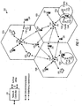
- FIGURE 1 shows a wireless communication network 100, which may be an LTE-A network, with fast frequency hopping for multi-carrier operations.
- the wireless network 100 includes a number of evolved node Bs (eNodeBs) 110 and other network entities.
- An eNodeB may be a station that communicates with the UEs and may also be referred to as a base station, a node B, an access point, and the like.
- Each eNodeB 110 may provide communication coverage for a particular geographic area.
- the term "cell" can refer to this particular geographic coverage area of an eNodeB and/or an eNodeB subsystem serving the coverage area, depending on the context in which the term is used.
- An eNodeB may provide communication coverage for a macro cell, a pico cell, a femto cell, and/or other types of cell.
- a macro cell generally covers a relatively large geographic area (e.g., several kilometers in radius) and may allow unrestricted access by UEs with service subscriptions with the network provider.
- a pico cell would generally cover a relatively smaller geographic area and may allow unrestricted access by UEs with service subscriptions with the network provider.
- a femto cell would also generally cover a relatively small geographic area (e.g., a home) and, in addition to unrestricted access, may also provide restricted access by UEs having an association with the femto cell (e.g., UEs in a closed subscriber group (CSG), UEs for users in the home, and the like).
- An eNodeB for a macro cell may be referred to as a macro eNodeB.
- An eNodeB for a pico cell may be referred to as a pico eNodeB.
- an eNodeB for a femto cell may be referred to as a femto eNodeB or a home eNodeB.
- the eNodeBs 110a, 110b and 110c are macro eNodeBs for the macro cells 102a, 102b and 102c, respectively.
- the eNodeB 110x is a pico eNodeB for a pico cell 102x.
- the eNodeBs 110y and 110z are femto eNodeBs for the femto cells 102y and 102z, respectively.
- An eNodeB may support one or multiple (e.g., two, three, four, and the like) cells.
- the wireless network 100 may also include relay stations.
- a relay station is a station that receives a transmission of data and/or other information from an upstream station (e.g., an eNodeB, UE, etc.) and sends a transmission of the data and/or other information to a downstream station (e.g., a UE or an eNodeB).
- a relay station may also be a UE that relays transmissions for other UEs.
- a relay station 110r may communicate with the eNodeB 110a and a UE 120r in order to facilitate communication between the eNodeB 110a and the UE 120r.
- a relay station may also be referred to as a relay eNodeB, a relay, etc.
- the wireless network 100 may be a heterogeneous network that includes eNodeBs of different types, e.g., macro eNodeBs, pico eNodeBs, femto eNodeBs, relays, etc. These different types of eNodeBs may have different transmit power levels, different coverage areas, and different impact on interference in the wireless network 100. For example, macro eNodeBs may have a high transmit power level (e.g., 20 Watts) whereas pico eNodeBs, femto eNodeBs and relays may have a lower transmit power level (e.g., 1 Watt).
- macro eNodeBs may have a high transmit power level (e.g., 20 Watts)
- pico eNodeBs, femto eNodeBs and relays may have a lower transmit power level (e.g., 1 Watt).
- the wireless network 100 may support synchronous or asynchronous operation.
- the eNodeBs may have similar frame timing, and transmissions from different eNodeBs may be approximately aligned in time.
- the eNodeBs may have different frame timing, and transmissions from different eNodeBs may not be aligned in time.
- the techniques described herein may be used for either synchronous or asynchronous operations.
- the wireless network 100 may support Frequency Division Duplex (FDD) or Time Division Duplex (TDD) modes of operation.
- FDD Frequency Division Duplex
- TDD Time Division Duplex
- the techniques described herein may be used for FDD or TDD mode of operation.
- a network controller 130 may couple to a set of eNodeBs 110 and provide coordination and control for these eNodeBs 110.
- the network controller 130 may communicate with the eNodeBs 110 via a backhaul.
- the eNodeBs 110 may also communicate with one another, e.g., directly or indirectly via a wireless backhaul or a wireline backhaul.
- the UEs 120 are dispersed throughout the wireless network 100, and each UE may be stationary or mobile.
- a UE may also be referred to as a terminal, a user terminal, a mobile station, a subscriber unit, a station, or the like.
- a UE may be a cellular phone (e.g., a smart phone), a personal digital assistant (PDA), a wireless modem, a wireless communication device, a handheld device, a laptop computer, a cordless phone, a wireless local loop (WLL) station, a tablet, a netbook, a smart book, or the like.
- PDA personal digital assistant
- a UE may be able to communicate with macro eNodeBs, pico eNodeBs, femto eNodeBs, relays, and the like.
- a solid line with double arrows indicates desired transmissions between a UE and a serving eNodeB, which is an eNodeB designated to serve the UE on the downlink and/or uplink.
- a dashed line with double arrows indicates interfering transmissions between a UE and an eNodeB.
- LTE utilizes orthogonal frequency division multiplexing (OFDM) on the downlink and single-carrier frequency division multiplexing (SC-FDM) on the uplink.
- OFDM and SC-FDM partition the system bandwidth into multiple (K) orthogonal subcarriers, which are also commonly referred to as tones, bins, or the like.
- K orthogonal subcarriers
- Each subcarrier may be modulated with data.
- modulation symbols are sent in the frequency domain with OFDM and in the time domain with SC-FDM.
- the spacing between adjacent subcarriers may be fixed, and the total number of subcarriers (K) may be dependent on the system bandwidth.
- the spacing of the subcarriers may be 15 kHz and the minimum resource allocation (called a 'resource block') may be 12 subcarriers (or 180 kHz). Consequently, the nominal FFT size may be equal to 128, 256, 512, 1024 or 2048 for a corresponding system bandwidth of 1.25, 2.5, 5, 10 or 20 megahertz (MHz), respectively.
- the system bandwidth may also be partitioned into sub-bands. For example, a sub-band may cover 1.08 MHz (i.e., 6 resource blocks), and there may be 1, 2, 4, 8 or 16 sub-bands for a corresponding system bandwidth of 1.25, 2.5, 5, 10, 15 or 20 MHz, respectively.
- FIGURE 2 shows a downlink FDD frame structure used in LTE.
- the transmission timeline for the downlink may be partitioned into units of radio frames.
- Each radio frame may have a predetermined duration (e.g., 10 milliseconds (ms)) and may be partitioned into 10 subframes with indices of 0 through 9.
- Each subframe may include two slots.
- Each radio frame may thus include 20 slots with indices of 0 through 19.
- Each slot may include L symbol periods, e.g., 7 symbol periods for a normal cyclic prefix (as shown in FIGURE 2 ) or 6 symbol periods for an extended cyclic prefix.
- the 2L symbol periods in each subframe may be assigned indices of 0 through 2L-1.
- the available time frequency resources may be partitioned into resource blocks.
- Each resource block may cover N subcarriers (e.g., 12 subcarriers) in one slot.
- an eNodeB may send a primary synchronization signal (PSC or PSS) and a secondary synchronization signal (SSC or SSS) for each cell in the eNodeB.
- PSC or PSS primary synchronization signal
- SSC or SSS secondary synchronization signal
- the primary and secondary synchronization signals may be sent in symbol periods 6 and 5, respectively, in each of subframes 0 and 5 of each radio frame with the normal cyclic prefix, as shown in FIGURE 2 .
- the synchronization signals may be used by UEs for cell detection and acquisition.
- the eNodeB may send a Physical Broadcast Channel (PBCH) in symbol periods 0 to 3 in slot 1 of subframe 0.
- PBCH Physical Broadcast Channel
- the eNodeB may send a Physical Control Format Indicator Channel (PCFICH) in the first symbol period of each subframe, as seen in FIGURE 2 .
- the eNodeB may send a Physical HARQ Indicator Channel (PHICH) and a Physical Downlink Control Channel (PDCCH) in the first M symbol periods of each subframe.
- the PDCCH and PHICH are also included in the first three symbol periods in the example shown in FIGURE 2 .
- the PHICH may carry information to support hybrid automatic repeat request (HARQ).
- the PDCCH may carry information on uplink and downlink resource allocation for UEs and power control information for uplink channels.
- the eNodeB may send a Physical Downlink Shared Channel (PDSCH) in the remaining symbol periods of each subframe.
- the PDSCH may carry data for UEs scheduled for data transmission on the downlink.
- the eNodeB may send the PSC, SSC and PBCH in the center 1.08 MHz of the system bandwidth used by the eNodeB.
- the eNodeB may send the PCFICH and PHICH across the entire system bandwidth in each symbol period in which these channels are sent.
- the eNodeB may send the PDCCH to groups of UEs in certain portions of the system bandwidth.
- the eNodeB may send the PDSCH to groups of UEs in specific portions of the system bandwidth.
- the eNodeB may send the PSC, SSC, PBCH, PCFICH and PHICH in a broadcast manner to all UEs, may send the PDCCH in a unicast manner to specific UEs, and may also send the PDSCH in a unicast manner to specific UEs.
- a number of resource elements may be available in each symbol period. Each resource element may cover one subcarrier in one symbol period and may be used to send one modulation symbol, which may be a real or complex value.
- the resource elements not used for a reference signal in each symbol period may be arranged into resource element groups (REGs). Each REG may include four resource elements in one symbol period.
- the PCFICH may occupy four REGs, which may be spaced approximately equally across frequency, in symbol period 0.
- the PHICH may occupy three REGs, which may be spread across frequency, in one or more configurable symbol periods. For example, the three REGs for the PHICH may all belong in symbol period 0 or may be spread in symbol periods 0, 1 and 2.
- the PDCCH may occupy 9, 18, 36 or 72 REGs, which may be selected from the available REGs, in the first M symbol periods. Only certain combinations of REGs may be allowed for the PDCCH.
- a UE may know the specific REGs used for the PHICH and the PCFICH.
- the UE may search different combinations of REGs for the PDCCH.
- the number of combinations to search is typically less than the number of allowed combinations for all UEs in the PDCCH.
- An eNodeB may send the PDCCH to the UE in any of the combinations that the UE will search.
- a UE may be within the coverage of multiple eNodeBs.
- One of these eNodeBs may be selected to serve the UE.
- the serving eNodeB may be selected based on various criteria such as received power, path loss, signal-to-noise ratio (SNR), etc.
- FIGURE 3 shows a block diagram of a design of a base station/eNodeB 110 and a UE 120, which may be one of the base stations/eNodeBs and one of the UEs in FIGURE 1 .
- the base station 110 may be the macro eNodeB 110c in FIGURE 1
- the UE 120 may be the UE 120y.
- the base station 110 may also be a base station of some other type.
- the base station 110 may be equipped with antennas 334a through 334t, and the UE 120 may be equipped with antennas 352a through 352r.
- a transmit processor 320 may receive data from a data source 312 and control information from a controller/processor 340.
- the control information may be for the PBCH, PCFICH, PHICH, PDCCH, etc.
- the data may be for the PDSCH, etc.
- the processor 320 may process (e.g., encode and symbol map) the data and control information to obtain data symbols and control symbols, respectively.
- the processor 320 may also generate reference symbols, e.g., for the PSS, SSS, and cell-specific reference signal.
- a transmit (TX) multiple-input multiple-output (MIMO) processor 330 may perform spatial processing (e.g., precoding) on the data symbols, the control symbols, and/or the reference symbols, if applicable, and may provide output symbol streams to the modulators (MODs) 332a through 332t.
- Each modulator 332 may process a respective output symbol stream (e.g., for OFDM, etc.) to obtain an output sample stream.
- Each modulator 332 may further process (e.g., convert to analog, amplify, filter, and upconvert) the output sample stream to obtain a downlink signal.
- Downlink signals from modulators 332a through 332t may be transmitted via the antennas 334a through 334t, respectively.
- the antennas 352a through 352r may receive the downlink signals from the base station 110 and may provide received signals to the demodulators (DEMODs) 354a through 354r, respectively.
- Each demodulator 354 may condition (e.g., filter, amplify, downconvert, and digitize) a respective received signal to obtain input samples.
- Each demodulator 354 may further process the input samples (e.g., for OFDM, etc.) to obtain received symbols.
- a MIMO detector 356 may obtain received symbols from all the demodulators 354a through 354r, perform MIMO detection on the received symbols if applicable, and provide detected symbols.
- a receive processor 358 may process (e.g., demodulate, deinterleave, and decode) the detected symbols, provide decoded data for the UE 120 to a data sink 360, and provide decoded control information to a controller/processor 380.
- a transmit processor 364 may receive and process data (e.g., for the PUSCH) from a data source 362 and control information (e.g., for the PUCCH) from the controller/processor 380.
- the processor 364 may also generate reference symbols for a reference signal.
- the symbols from the transmit processor 364 may be precoded by a TX MIMO processor 366 if applicable, further processed by the demodulators 354a through 354r (e.g., for SC-FDM, etc.), and transmitted to the base station 110.
- the uplink signals from the UE 120 may be received by the antennas 334, processed by the modulators 332, detected by a MIMO detector 336 if applicable, and further processed by a receive processor 338 to obtain decoded data and control information sent by the UE 120.
- the processor 338 may provide the decoded data to a data sink 339 and the decoded control information to the controller/processor 340.
- the controllers/processors 340 and 380 may direct the operation at the base station 110 and the UE 120, respectively.
- the processor 340 and/or other processors and modules at the base station 110 may perform or direct the execution of various processes for the techniques described herein.
- the processor 380 and/or other processors and modules at the UE 120 may also perform or direct the execution of the functional blocks illustrated in FIGS. 4 and 5 , and/or other processes for the techniques described herein.
- the memories 342 and 382 may store data and program codes for the base station 110 and the UE 120, respectively.
- a scheduler 344 may schedule UEs for data transmission on the downlink and/or uplink.
- LTE-Advanced UEs use spectrum in up to 20 MHz bandwidths allocated in a carrier aggregation of up to a total of 100 MHz (5 component carriers) used for transmission in each direction.
- the uplink spectrum allocation may be smaller than the downlink allocation.
- the downlink may be assigned 100 Mhz.
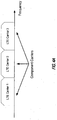
- Non-continuous CA occurs when multiple available component carriers are separated along the frequency band ( FIGURE 4B ).
- continuous CA occurs when multiple available component carriers are adjacent to each other ( FIGURE 4A ).
- Both non-continuous and continuous CA aggregate multiple LTE/component carriers to serve a single unit of LTE Advanced UE.
- Non-continuous CA supports data transmissions over multiple separated carriers across a large frequency range, propagation path loss, Doppler shift and other radio channel characteristics may vary a lot at different frequency bands.
- methods may be used to adaptively adjust coding, modulation and transmission power for different component carriers.
- eNodeB enhanced NodeB
- the effective coverage or supportable modulation and coding of each component carrier may be different.
- FIGURE 5 illustrates aggregating transmission blocks (TBs) from different component carriers at the medium access control (MAC) layer ( FIGURE 5 ) for an IMT-Advanced system.
- MAC medium access control
- each component carrier has its own independent hybrid automatic repeat request (HARQ) entity in the MAC layer and its own transmission configuration parameters (e.g., transmitting power, modulation and coding schemes, and multiple antenna configuration) in the physical layer.
- HARQ hybrid automatic repeat request
- transmitting power e.g., transmitting power, modulation and coding schemes, and multiple antenna configuration
- one HARQ entity is provided for each component carrier.
- control channel signaling for multiple component carriers.
- the second method involves jointly coding the control channels of different component carriers and deploying the control channels in a dedicated component carrier.
- the control information for the multiple component carriers will be integrated as the signaling content in this dedicated control channel.
- control channels for different component carriers are jointly coded and then transmitted over the entire frequency band formed by a third CA method.
- This approach offers low signaling overhead and high decoding performance in control channels, at the expense of high power consumption at the UE side.
- this method is not compatible with LTE systems.
- the UE measures the performance of only one component carrier in each adjacent cell. This offers similar measurement delay, complexity, and energy consumption as that in LTE systems. An estimate of the performance of the other component carriers in the corresponding cell may be based on the measurement result of the one component carrier. Based on this estimate, the handover decision and transmission configuration may be determined.
- the UE operating in a multicarrier system is configured to aggregate certain functions of multiple carriers, such as control and feedback functions, on the same carrier, which may be referred to as a "primary carrier.”
- the remaining carriers that depend on the primary carrier for support are referred to as associated secondary carriers.
- the UE may aggregate control functions such as those provided by the optional dedicated channel (DCH), the nonscheduled grants, a physical uplink control channel (PUCCH), and/or a physical downlink control channel (PDCCH).
- DCH optional dedicated channel
- PUCCH physical uplink control channel
- PDCCH physical downlink control channel
- secondary carriers may be added or removed without affecting the basic operation of the UE, including physical channel establishment and RLF procedures which are layer 2 and layer 3 procedures, such as in the 3GPP technical specification 36.331 for the LTE RRC protocol.
- FIGURE 6 illustrates a method 600 for controlling radio links in a multiple carrier wireless communication system by grouping physical channels according to one example.
- the method includes, at block 605, aggregating control functions from at least two carriers onto one carrier to form a primary carrier and one or more associated secondary carriers.
- communication links are established for the primary carrier and each secondary carrier. Then, communication is controlled based on the primary carrier in block 615.
- Certain available carriers may be partitioned by time division multiplexing (TDM) to provide nodes with at least one resource that is protected from dominant interference. This may involve coordination with potential interfering nodes to restrict transmission by the interferer on the protected resources.
- a protected resource may include one subframe out of a periodically repeating pattern of subframes on a particular carrier, denoted the "primary carrier” or “anchor carrier” for example. Transmissions on the protected resources are reliable because of the time domain partitioning.
- Unprotected subframes on the primary carrier may be subject to interference.
- Other carriers that do not include protected resources denoted as “unprotected secondary carriers,” may also be subject to interference. Interference can be mitigated or avoided by allowing communication only over the protected resources or by avoiding the use of unprotected resources. It should be understood that even protected resources may be subject to some level of interference from nodes not involved in the coordinated resource protection scheme.
- the unprotected secondary carrier may be a secondary carrier of a carrier aggregation (CA) implementation, or may be a carrier within some unrelated or unlicensed spectrum, for example, white space.
- White space is a term used to refer to unused broadcast spectrum.
- Use of currently unused or unlicensed spectrum provides an advantage due to its lower cost when compared to licensed spectrum.
- the licensed spectrum may be used for transmitting the control information with high reliability, while unlicensed spectrum may be used for transmitting data less reliably than the control information.
- the unprotected secondary carriers may also convey data to a UE, for example.
- the reliability of an unprotected secondary carrier generally depends on the strength of an interfering transmitter, the distance to the interfering transmitter, and loading of the unprotected secondary carrier.
- RLFs radio link failures
- CA carrier aggregation
- a UE that employs only one RF receiver may still operate on both a primary carrier and an unprotected secondary carrier by performing fast frequency hopping between the two carriers.
- the UE periodically returns to the primary carrier to maintain a reliable connection.
- the eNodeB follows the same frequency hopping pattern as the UE to maintain the connection.
- the eNodeB may decide to offload data to secondary carriers, depending on reported channel conditions of the secondary carriers.
- This frequency hopping technique may also be used in the uplink communications in which the UE transmitter periodically switches between a primary and a secondary carrier.
- aspects of the present disclosure can be used in frequency division duplex (FDD) communications in which physical layer synchronization may be maintained on several carriers.
- Idle mode operations such as system information block 1 (SIB1) delivery, paging, and measurements may be performed on the primary carrier, which is time domain partitioned.
- Connected mode operations may be performed on two carriers, the primary carrier and an unprotected secondary carrier, through frequency hopping.
- the periodic changes between radio frequencies is performed in a short time, generally using only tens or hundreds of ⁇ s.
- the periodic frequency changes may be implemented without substantially increasing energy consumption.
- multicarrier operations are performed for downlink (DL) transmissions only and a single protected carrier is available for uplink (UL) transmissions.
- Most of transmissions to the UE are over an unprotected carrier and the UE periodically retunes to the primary carrier.
- the primary carrier can be used to communicate control information between a UE and an eNodeB or other transmitting node and to communicate whether the unprotected secondary carrier is still usable. It is envisioned that all or most of the data transmissions will be performed on the unprotected secondary carrier. If the unprotected secondary carrier becomes unusable, then a different unprotected secondary carrier can be designated in a grant to the UE or the primary carrier can be used for data transmission, without any offloading to a secondary carrier.
- the UE receives a primary carrier downlink control information (DCI) grant and a secondary carrier DCI grant.
- DCI downlink control information
- a downlink grant may carry control information for data transmission on the downlink.
- the primary carrier DCI grant is for the U subframe (protected subframe) on the primary carrier.
- the secondary carrier DCI grant is for particular subframes on the secondary carrier.
- the secondary carrier DCI grant may include bits indicating which carrier to use in cases where several carriers may be available. If a number (M) carriers are available, for example, as few as log2(M) bits may be used to identify the secondary carrier.
- the DCI grant may also indicate a number of subframes affected by the grant. In this example, up to seven subframes may be affected depending on the downlink queue length.
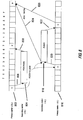
- FIGURE 7 a diagram of a primary carrier for a downlink transmission is shown.
- the primary carrier is time division partitioned into subframes of about 1 millisecond each.
- the subframes are sequentially labeled with a pattern of numbers from 0 to 7 which periodically repeat.
- the primary carrier is divided into a pattern of eight repeating subframes, it should be understood that virtually any number of repeating subframes could be used.
- the UE only uses one periodically repeating subframe, denoted the "U" subframe, on the primary carrier.
- the U subframe is protected from interference by coordination with potentially interfering transmitters, so it can be reliably transmit data to the UE. It should be apparent that capacity would be significantly reduced if all transmissions were restricted to the protected U subframes.
- a diagram of an unprotected secondary carrier 704 is shown juxtaposed in time with the primary carrier 702. Again, it should be noted that a UE having a single receiver may not use the primary carrier 702 and the unprotected secondary carrier 704 at the same time.
- a UE receiver circuitry tunes to the primary carrier 702.
- the UE decodes the signal received on the protected "U" subframe.
- the downlink U subframe includes a few bits indicating the unprotected secondary carrier to use for the next subframes.
- the number of subframes and/or periods to which this carrier indication refers to may also be included in the U subframe, for example.
- the UE retunes its receiver to the unprotected secondary carrier 704.
- the retuning takes some short time as shown by diagonal arrow 706 which is usually much less than the duration of a subframe.
- the UE receives only the PDSCH data on the unprotected secondary carrier. Control signals such as PHICH, and PDCCH are received on the primary carrier 702.
- transition subframes are not completely available. This can be seen in FIGURE 7 where the transition time represented by diagonal arrow 706 uses a portion of transition subframe 0, and the transition time represented by diagonal arrow 708 uses a portion of transition subframe 6, for example. Because the transition subframes are not entirely available for use on the secondary carrier, they may either be completely skipped or may be partially used. The transition subframes may be partially used by skipping only a few OFDM symbols at the beginning or at the end of the transition subframes, for example.
- symbols to be skipped should be known at both the eNodeB and the UE. This may be accomplished by puncturing some existing symbols, moving some existing symbols away from the transition subframes, or moving them away from the respective terminal ends of the transition subframes.
- the UE After a time corresponding to a number of subframes between U subframes has passed minus enough time to complete a retuning operation, the UE retunes to the primary carrier 702.
- the transition time allowed for retuning should be long enough that the UE will have time to decode the next U subframe on the primary carrier 702. This transition is shown by diagonal arrow 708. This sequence of transitions between the primary carrier 702 and the unprotected secondary carrier 704 repeats periodically.
- FIGURE 7 also shows an example of an HARQ timeline.that can correspond to the disclosed frequency hopping scheme.
- a UE generates one ACK or NACK bit (ACK/NACK) for each subframe where data has been received.
- the ACK/NACKs corresponding to the subframes where data has been received on the unprotected secondary carrier 704 are bundled or multiplexed and fed back using the same PUCCH resources on a protected uplink resource 714 of a protected uplink carrier 716.
- the ACK/NACK corresponding to the U subframe on the primary carrier 702 is also fed back using the same PUCCH resources on a protected uplink resource 714 but kept separate from the combined ACK/NACK of the secondary carrier.
- the protected uplink resource may be a time division partitioned subframe on the protected uplink carrier 716.
- Various previously known methods can be used for multiplexing or merging the ACK/NACKs.
- a UE may report multiple channel quality indications (CQIs), to include one channel quality indication for each carrier being used.
- CQIs channel quality indications
- the UE may also report CQI for carriers not currently used.
- an eNodeB may instruct a UE to generate a CQI for any number of particular carriers.
- a new periodic reporting mode may be defined, for example, in which a UE cycles through a set of carriers for each periodic reporting.
- the set of carriers may be provided to the UE by an eNodeB's upper layers.
- transmissions on the secondary carrier can be discontinued.
- a new secondary carrier can be selected and a grant for resources on the new secondary carrier can be provided to the UE.
- multicarrier operations are performed for downlink (DL) transmissions and also for uplink (UL) transmissions.
- Most of transmissions to the UE are carried out over an unprotected downlink carrier and most of the transmissions from the UE are carried out over an unprotected uplink carrier.
- the UE periodically retunes its receiver circuitry between the downlink primary carrier and the unprotected downlink secondary carrier.
- the UE also periodically retunes its transmitter circuitry between the uplink primary carrier and the unprotected uplink secondary carrier.
- the UE receives a primary carrier uplink control information (UCI) grant and a secondary carrier UCI grant.
- Uplink control information provides a hybrid-ARQ protocol and a scheduler with information about the UE.
- An uplink grant may carry control information for data transmission on the uplink.
- the primary carrier UCI grant is for the U subframe on the primary carrier.
- the secondary carrier UCI grant is for particular subframes on the secondary carrier.
- the U subframes of an uplink primary carrier are offset from the U subframes of a downlink primary carrier by a fixed number of subframes.
- FIGURE 8 a diagram of a downlink primary carrier for a downlink transmission 802 is shown and a diagram of an unprotected downlink secondary carrier 804 is shown juxtaposed in time with the downlink primary carrier 802.
- UE receiver circuitry tunes to the downlink primary carrier 802 during the U subframe of the downlink primary carrier 802.
- the UE decodes the signal received on the U subframe.
- the UE retunes its receiver to the unprotected downlink secondary carrier 804 as shown by diagonal arrow 806.
- the UE receives data on the unprotected downlink secondary carrier 804.
- the UE After a time corresponding to a number of subframes between U subframes has passed minus enough time to complete a retuning operation, the UE retunes to the downlink primary carrier 802 as shown by diagonal arrow 808. This sequence of downlink transitions between the downlink primary carrier 802 and the unprotected downlink secondary carrier 804 repeats periodically.
- the UE transmitter circuitry tunes to the uplink primary carrier 816 during a U subframe of the uplink primary carrier 816.
- the UE transmits a signal on the U subframe then retunes its transmitter circuitry to the unprotected uplink secondary carrier 818 as shown by diagonal arrow 820.
- the UE transmits data on the unprotected uplink secondary carrier 818.
- the UE retunes its transmitter circuitry to the uplink primary carrier 816 as shown by diagonal arrow 822. This sequence of uplink transitions between the uplink primary carrier 816 and the unprotected uplink secondary carrier 818 repeats periodically.
- ACK/NACKs corresponding to the subframes where data has been received by an eNodeB on the unprotected uplink secondary carrier 818 may be bundled or multiplexed and fed back to the UE in a U subframe of the downlink primary carrier 802 as shown by arrow 824.
- An ACK/NACK corresponding to the U subframe received by an eNodeB on the uplink primary carrier 816 may be kept separate from the combined ACK/NACK of the secondary carrier but may also be fed back to the UE in a U subframe of the downlink primary carrier 802 as shown by arrow 826.
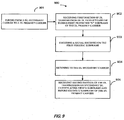
- the method 900 includes tuning to a downlink primary carrier at block 901.
- a single receiver of a user equipment (UE) receives a first portion of a downlink transmission from an eNode B (eNodeB) on the downlink primary carrier during a first periodic subframe of the downlink primary carrier.
- eNodeB eNode B
- decoding of a signal received on the first periodic subframe which in one example is a U subframe, occurs.
- the method retunes to a downlink secondary carrier, which in one example is an unprotected secondary carrier.
- the method then receives by the single receiver a second portion of the downlink transmission from the eNodeB on a secondary downlink carrier, at block 905.
- the reception occurs during a periodic sequence of subframes of the secondary downlink carrier following the first periodic subframe of the downlink primary carrier and before a second periodic subframe of the downlink primary carrier.
- the single receiver may then receive a third portion of the downlink transmission from the eNodeB on the downlink primary carrier during the second periodic subframe of the downlink primary carrier.
- the method may also include transmitting by a single transmitter of the UE an uplink transmission to the eNodeB on an uplink primary carrier during a first periodic subframe of the uplink primary carrier.
- the single transmitter then transmits the uplink transmission to the eNodeB on a secondary uplink carrier during a periodic sequence of subframes of the secondary uplink carrier following the first periodic subframe of the uplink primary carrier and before a second periodic subframe of the uplink primary carrier.
- the single transmitter transmits the uplink transmission to the eNodeB on the uplink primary carrier during the second periodic subframe of the uplink primary carrier.
- the method 1000 includes tuning to a downlink primary carrier at block 1001.
- eNodeB eNode B
- retuning to a secondary downlink carrier occurs.
- the method transmits (block 1004) to the single receiver a second portion of the downlink transmission by the eNodeB on a secondary downlink carrier.
- the transmission occurs during a periodic sequence of subframes of the secondary downlink carrier following the first periodic subframe of the downlink primary carrier and before a second periodic subframe of the downlink primary carrier.
- the eNodeB then transmits to the single receiver the downlink transmission on the downlink primary carrier during the second periodic subframe of the downlink primary carrier.
- the method may also include receiving from a single transmitter of the UE an uplink transmission on an uplink primary carrier during a first periodic subframe of the uplink primary carrier.
- the eNodeB then receives from the single transmitter the uplink transmission on a secondary uplink carrier during a periodic sequence of subframes of the secondary uplink carrier following the first periodic subframe of the uplink primary carrier and before a second periodic subframe of the uplink primary carrier.
- the eNodeB then receives from the single transmitter the uplink transmission on the uplink primary carrier during the second periodic subframe of the uplink primary carrier.
- the method 1100 includes tuning to an uplink primary carrier at block 1101.
- the eNodeB receives an uplink transmission from a UE on an uplink primary carrier during a first periodic subframe of the uplink primary carrier.
- decoding a signal received on the first periodic subframe which in one example is a U subframe, occurs.
- retuning to an uplink secondary carrier which in one example is an unprotected secondary carrier, occurs.
- the method then receives, at block 1105, the uplink transmission from the UE on a secondary downlink carrier during a periodic sequence of subframes of the secondary uplink carrier following the first periodic subframe of the uplink primary carrier and before a second periodic subframe of the uplink primary carrier.
- the eNodeB may then receive the uplink transmission on the uplink primary carrier during the second periodic subframe of the uplink primary carrier.
- the method 1200 includes tuning to an uplink primary carrier at block 1201.
- a UE transmits to an eNodeB an uplink transmission on the uplink primary carrier during a first periodic subframe of the uplink primary carrier.
- retuning to a secondary uplink carrier occurs.
- the method then transmits (at block 1204) to the eNodeB the uplink transmission on a secondary uplink carrier during a periodic sequence of subframes of the secondary uplink carrier following the first periodic subframe of the uplink primary carrier and before a second periodic subframe of the uplink primary carrier.
- the UE may then transmit to the eNodeB the uplink transmission on the uplink primary carrier during the second periodic subframe of the uplink primary carrier.
- the UE 120 is configured for wireless communication and includes receiving means.
- the aforementioned receiving means may be the antenna 352A-T, demodulator 354A-T, receive processor 358, controller processor 380, and/or memory 382 configured to perform the functions recited by the aforementioned means.
- the aforementioned means may be any module or any apparatus configured to perform the functions recited by the aforementioned means.
- the eNodeB 110 is configured for wireless communication and includes transmitting means configured to perform the functions recited by the aforementioned means.
- the aforementioned transmitting means may be the antenna 334A-T, modulator 332A-T, transmit processor 320, controller processor 340, and/or memory 342 configured to perform the functions recited by the aforementioned means.
- the aforementioned means may be any module or any apparatus configured to perform the functions recited by the aforementioned means.
- FIG. 13 is a diagram illustrating an example of a hardware implementation for an apparatus 120 employing a processing system 1314.
- the processing system 1314 may be implemented with a bus architecture, represented generally by the bus 1324.
- the bus 1324 may include any number of interconnecting buses and bridges depending on the specific application of the processing system 1314 and the overall design constraints.
- the bus 1324 links together various circuits including one or more processors and/or hardware modules, represented by the processor 1304, the modules 1308, 1309 and the computer-readable medium 1306.
- the bus 1324 may also link various other circuits such as timing sources, peripherals, voltage regulators, and power management circuits, which are well known in the art, and therefore, will not be described any further.
- the apparatus includes a processing system 1314 coupled to a transceiver 1310.
- the transceiver 1310 is coupled to one or more antennas 1320.
- the transceiver 1310 provides a means for communicating with various other apparatus over a transmission medium.
- the processing system 1314 includes a processor 1304 coupled to a computer-readable medium 1306.
- the processor 1304 is responsible for general processing, including the execution of software stored on the computer-readable medium 1306.
- the software when executed by the processor 1304, causes the processing system 1314 to perform the various functions described supra for any particular apparatus.
- the computer-readable medium 1306 may also be used for storing data that is manipulated by the processor 1304 when executing software.
- the processing system further includes receiving modules 1308, 1309.
- the modules may be software modules running in the processor 1304, resident/stored in the computer readable medium 1306, one or more hardware modules coupled to the processor 304, or some combination thereof.
- the processing system 1314 may be a component of the UE 120 and may include the memory 382 and/or at least one of the TX processor 364, the RX processor 358, and the controller/processor 380.
- the apparatus 120 for wireless communication includes means for receiving.
- the aforementioned means may be one or more of the aforementioned modules of the apparatus 120 and/or the processing system 1314 of the apparatus 120 configured to perform the functions recited by the aforementioned means.
- DSP digital signal processor
- ASIC application specific integrated circuit
- FPGA field programmable gate array
- a general-purpose processor may be a microprocessor, but in the alternative, the processor may be any conventional processor, controller, microcontroller, or state machine.
- a processor may also be implemented as a combination of computing devices, e.g., a combination of a DSP and a microprocessor, a plurality of microprocessors, one or more microprocessors in conjunction with a DSP core, or any other such configuration.
- a software module may reside in RAM memory, flash memory, ROM memory, EPROM memory, EEPROM memory, registers, hard disk, a removable disk, a CD-ROM, or any other form of storage medium known in the art.
- An exemplary storage medium is coupled to the processor such that the processor can read information from, and write information to, the storage medium.
- the storage medium may be integral to the processor.
- the processor and the storage medium may reside in an ASIC.
- the ASIC may reside in a user terminal.
- the processor and the storage medium may reside as discrete components in a user terminal.
- the functions described may be implemented in hardware, software, firmware, or any combination thereof. If implemented in software, the functions may be stored on or transmitted over as one or more instructions or code on a computer-readable medium.
- Computer-readable media includes both non-transitory computer storage media and communication media including any medium that facilitates transfer of a computer program from one place to another.
- a storage media may be any available media that can be accessed by a general purpose or special purpose computer.
- non-transitory computer-readable media can comprise RAM, ROM, EEPROM, CD-ROM or other optical disk storage, magnetic disk storage or other magnetic storage devices, or any other medium that can be used to store desired program code means in the form of instructions or data structures and that can be accessed by a general-purpose or special-purpose computer, or a general-purpose or special-purpose processor. Also, any connection is properly termed a computer-readable medium.
- Disk and disc includes compact disc (CD), laser disc, optical disc, digital versatile disc (DVD), floppy disk and blu-ray disc where disks usually reproduce data magnetically, while discs reproduce data optically with lasers. Combinations of the above should also be included within the scope of computer-readable media.
Landscapes
- Engineering & Computer Science (AREA)
- Signal Processing (AREA)
- Computer Networks & Wireless Communication (AREA)
- Mobile Radio Communication Systems (AREA)
Applications Claiming Priority (3)
| Application Number | Priority Date | Filing Date | Title |
|---|---|---|---|
| US201161446940P | 2011-02-25 | 2011-02-25 | |
| US13/403,933 US9294240B2 (en) | 2011-02-25 | 2012-02-23 | Multi-carrier operations with fast frequency hopping |
| PCT/US2012/026498 WO2012116273A1 (en) | 2011-02-25 | 2012-02-24 | Multi-carrier operations with fast frequency hopping |
Publications (2)
| Publication Number | Publication Date |
|---|---|
| EP2678968A1 EP2678968A1 (en) | 2014-01-01 |
| EP2678968B1 true EP2678968B1 (en) | 2018-03-21 |
Family
ID=46718951
Family Applications (1)
| Application Number | Title | Priority Date | Filing Date |
|---|---|---|---|
| EP12708453.1A Active EP2678968B1 (en) | 2011-02-25 | 2012-02-24 | Multi-carrier operations with fast frequency hopping |
Country Status (6)
| Country | Link |
|---|---|
| US (1) | US9294240B2 (zh) |
| EP (1) | EP2678968B1 (zh) |
| JP (2) | JP5801422B2 (zh) |
| KR (1) | KR101593052B1 (zh) |
| CN (1) | CN103404070B (zh) |
| WO (1) | WO2012116273A1 (zh) |
Cited By (1)
| Publication number | Priority date | Publication date | Assignee | Title |
|---|---|---|---|---|
| US11723032B2 (en) | 2020-05-18 | 2023-08-08 | Comcast Cable Communications, Llc | Transmission using a plurality of wireless resources |
Families Citing this family (23)
| Publication number | Priority date | Publication date | Assignee | Title |
|---|---|---|---|---|
| US9197390B2 (en) * | 2011-08-12 | 2015-11-24 | Panasonic Intellectual Property Corporation Of America | Communication device, and retransmission control method |
| US9603124B2 (en) * | 2012-04-24 | 2017-03-21 | Apple Inc. | Methods and apparatus for opportunistic radio resource allocation in multi-carrier communication systems |
| EP2893759B1 (en) * | 2012-09-07 | 2020-12-30 | Samsung Electronics Co., Ltd. | Method and apparatus for signalling resource allocation information in an asymmetric multicarrier communication network |
| JP6150487B2 (ja) * | 2012-10-09 | 2017-06-21 | 株式会社Nttドコモ | ユーザ端末、無線基地局、無線通信システム及び無線通信方法 |
| US9730207B2 (en) * | 2013-01-31 | 2017-08-08 | Lg Electronics Inc. | Communication method using carrier aggregation and apparatus for same |
| KR102025385B1 (ko) * | 2013-02-26 | 2019-11-27 | 삼성전자주식회사 | 셀 내의 캐리어 집적 시스템에서 단말의 능력에 따른 제어 채널 전송 방법 및 장치 |
| US9642140B2 (en) * | 2013-06-18 | 2017-05-02 | Samsung Electronics Co., Ltd. | Methods of UL TDM for inter-enodeb carrier aggregation |
| US9307556B2 (en) * | 2013-07-23 | 2016-04-05 | Nokia Solutions And Networks Oy | Shared access of uplink carrier |
| US9591644B2 (en) * | 2013-08-16 | 2017-03-07 | Qualcomm Incorporated | Downlink procedures for LTE/LTE-A communication systems with unlicensed spectrum |
| EP3043610B1 (en) * | 2013-09-27 | 2019-09-04 | Huawei Technologies Co., Ltd. | Communication method, user equipment and base station |
| US9825748B2 (en) | 2014-02-03 | 2017-11-21 | Apple Inc. | Offloading and reselection policies and rules for mobile devices |
| DE102015201432B4 (de) * | 2014-02-03 | 2022-07-14 | Apple Inc. | Verfahren und Vorrichtungen zur Kommunikation in nicht -lizenzierten Funkfrequenzbändern durch mobile drahtlose Vorrichtungen |
| EP3200545B1 (en) * | 2014-09-26 | 2019-11-20 | Nanchang Coolpad Intelligent Technology Company Limited | Data transmission method and system, and device having base station function |
| US9756058B1 (en) | 2014-09-29 | 2017-09-05 | Amazon Technologies, Inc. | Detecting network attacks based on network requests |
| US9426171B1 (en) | 2014-09-29 | 2016-08-23 | Amazon Technologies, Inc. | Detecting network attacks based on network records |
| US20160227568A1 (en) * | 2015-01-30 | 2016-08-04 | Htc Corporation | Method of Handling Carrier Grouping and Related Communication Device |
| WO2016130073A1 (en) * | 2015-02-09 | 2016-08-18 | Telefonaktiebolaget Lm Ericsson (Publ) | Implementation of harq on pusch for multiple carriers |
| CN107431555B (zh) * | 2015-03-31 | 2020-01-10 | 索尼公司 | 装置 |
| CN106059980B (zh) * | 2016-05-27 | 2019-03-29 | 电子科技大学 | 一种基于快速跳频的多载波扩频方法 |
| WO2018006237A1 (en) * | 2016-07-04 | 2018-01-11 | Intel IP Corporation | Downlink control information (dci) configuration |
| KR102397784B1 (ko) * | 2018-06-21 | 2022-05-12 | 에프쥐 이노베이션 컴퍼니 리미티드 | 무선 통신 시스템에서 셀 (재)선택을 수행하기 위한 방법 및 장치 |
| JP7108053B2 (ja) | 2018-09-06 | 2022-07-27 | グーグル エルエルシー | 馴染みのあるロケーションを中間目的地とするナビゲーション指示 |
| WO2021062856A1 (en) * | 2019-10-01 | 2021-04-08 | Qualcomm Incorporated | Handling uplink channel and carrier switching gap collisions |
Family Cites Families (15)
| Publication number | Priority date | Publication date | Assignee | Title |
|---|---|---|---|---|
| US8767713B2 (en) * | 2005-02-22 | 2014-07-01 | Qualcomm Incorporated | Apparatus and method for allowing page monitoring of a communication system during traffic/broadcast channel operation without reducing traffic performance |
| US8000272B2 (en) | 2007-08-14 | 2011-08-16 | Nokia Corporation | Uplink scheduling grant for time division duplex with asymmetric uplink and downlink configuration |
| CN101978721B (zh) * | 2008-04-24 | 2013-07-31 | 夏普株式会社 | 移动站装置、移动通信系统以及通信方法 |
| US9397775B2 (en) | 2008-09-12 | 2016-07-19 | Blackberry Limited | Frequency division duplexing and half duplex frequency division duplexing in multihop relay networks |
| WO2010044632A2 (ko) * | 2008-10-15 | 2010-04-22 | 엘지전자주식회사 | 다중 반송파 시스템에서 통신 방법 및 장치 |
| US8243648B2 (en) * | 2008-12-19 | 2012-08-14 | Intel Corporation | Spatial reuse techniques with wireless network relays |
| US8681724B2 (en) | 2009-01-07 | 2014-03-25 | Nokia Siemens Networks Oy | Discontinuous reception in carrier aggregation wireless communication systems |
| WO2010088536A1 (en) | 2009-01-30 | 2010-08-05 | Interdigital Patent Holdings, Inc. | Method and apparatus for component carrier aggregation in wireless communications |
| US20100271970A1 (en) * | 2009-04-22 | 2010-10-28 | Interdigital Patent Holdings, Inc. | Method and apparatus for transmitting uplink control information for carrier aggregated spectrums |
| WO2010141618A1 (en) | 2009-06-02 | 2010-12-09 | Research In Motion Limited | System and method for power control for carrier aggregation using single power control message for multiple carriers |
| US9118468B2 (en) * | 2009-07-23 | 2015-08-25 | Qualcomm Incorporated | Asynchronous time division duplex operation in a wireless network |
| KR101707867B1 (ko) | 2009-07-28 | 2017-02-17 | 엘지전자 주식회사 | 다중반송파 지원 광대역 무선 통신 시스템에서의 반송파 관리 절차 수행 방법 및 장치 |
| CN102111851B (zh) | 2009-12-23 | 2014-06-18 | 中兴通讯股份有限公司南京分公司 | 一种实现下行控制信令传输的方法及系统 |
| US8555128B2 (en) * | 2010-03-24 | 2013-10-08 | Futurewei Technologies, Inc. | System and method for transmitting and receiving acknowledgement information |
| CN101867953B (zh) | 2010-06-13 | 2015-06-03 | 中兴通讯股份有限公司 | 载波聚合场景下下行控制信息的检测方法和用户设备 |
-
2012
- 2012-02-23 US US13/403,933 patent/US9294240B2/en active Active
- 2012-02-24 CN CN201280010258.9A patent/CN103404070B/zh active Active
- 2012-02-24 WO PCT/US2012/026498 patent/WO2012116273A1/en active Application Filing
- 2012-02-24 JP JP2013555595A patent/JP5801422B2/ja active Active
- 2012-02-24 EP EP12708453.1A patent/EP2678968B1/en active Active
- 2012-02-24 KR KR1020137025253A patent/KR101593052B1/ko active IP Right Grant
-
2015
- 2015-05-13 JP JP2015098426A patent/JP2015181258A/ja active Pending
Cited By (1)
| Publication number | Priority date | Publication date | Assignee | Title |
|---|---|---|---|---|
| US11723032B2 (en) | 2020-05-18 | 2023-08-08 | Comcast Cable Communications, Llc | Transmission using a plurality of wireless resources |
Also Published As
| Publication number | Publication date |
|---|---|
| JP2014511060A (ja) | 2014-05-01 |
| EP2678968A1 (en) | 2014-01-01 |
| WO2012116273A1 (en) | 2012-08-30 |
| CN103404070A (zh) | 2013-11-20 |
| JP5801422B2 (ja) | 2015-10-28 |
| US9294240B2 (en) | 2016-03-22 |
| KR101593052B1 (ko) | 2016-02-11 |
| KR20130133000A (ko) | 2013-12-05 |
| CN103404070B (zh) | 2016-08-10 |
| US20120218954A1 (en) | 2012-08-30 |
| JP2015181258A (ja) | 2015-10-15 |
Similar Documents
| Publication | Publication Date | Title |
|---|---|---|
| EP2678968B1 (en) | Multi-carrier operations with fast frequency hopping | |
| CN109075953B (zh) | 处理因载波切换引起的中断和载波切换能力指示 | |
| EP3142408B1 (en) | System and method for managing invalid reference subframes for channel state information feedback | |
| EP2817996B1 (en) | Mitigating cross-device interference | |
| EP2737654B1 (en) | Method and apparatus for signaling control data of aggregated carriers | |
| US8576791B2 (en) | Sharing control channel resources | |
| KR101602242B1 (ko) | 롱 텀 에벌루션에서 강화된 물리적 다운링크 제어 채널의 구조 | |
| EP2678967B1 (en) | System and method for single carrier optimization for evolved multimedia broadcast multicast service | |
| US9030971B2 (en) | Simultaneous operation of short range wireless systems with a mobile wireless broadband system | |
| US20120106404A1 (en) | Fdd and tdd carrier aggregation | |
| WO2013112848A2 (en) | Ue-initiated dynamic activation and de-activation of secondary carriers | |
| US20120058797A1 (en) | Power control on a deactivated component carrier | |
| WO2012115726A1 (en) | Enhanced multimedia broadcast multicast service carriers in carrier aggregation | |
| US10952193B2 (en) | LTE-TDD carrier aggregation enhancement for half-duplex UES | |
| KR20140106505A (ko) | Tdd 캐리어 어그리게이션을 위한 하프-듀플렉스/풀-듀플렉스 동작 |
Legal Events
| Date | Code | Title | Description |
|---|---|---|---|
| PUAI | Public reference made under article 153(3) epc to a published international application that has entered the european phase |
Free format text: ORIGINAL CODE: 0009012 |
|
| 17P | Request for examination filed |
Effective date: 20130911 |
|
| AK | Designated contracting states |
Kind code of ref document: A1 Designated state(s): AL AT BE BG CH CY CZ DE DK EE ES FI FR GB GR HR HU IE IS IT LI LT LU LV MC MK MT NL NO PL PT RO RS SE SI SK SM TR |
|
| DAX | Request for extension of the european patent (deleted) | ||
| GRAP | Despatch of communication of intention to grant a patent |
Free format text: ORIGINAL CODE: EPIDOSNIGR1 |
|
| STAA | Information on the status of an ep patent application or granted ep patent |
Free format text: STATUS: GRANT OF PATENT IS INTENDED |
|
| INTG | Intention to grant announced |
Effective date: 20170508 |
|
| GRAS | Grant fee paid |
Free format text: ORIGINAL CODE: EPIDOSNIGR3 |
|
| GRAJ | Information related to disapproval of communication of intention to grant by the applicant or resumption of examination proceedings by the epo deleted |
Free format text: ORIGINAL CODE: EPIDOSDIGR1 |
|
| GRAL | Information related to payment of fee for publishing/printing deleted |
Free format text: ORIGINAL CODE: EPIDOSDIGR3 |
|
| STAA | Information on the status of an ep patent application or granted ep patent |
Free format text: STATUS: REQUEST FOR EXAMINATION WAS MADE |
|
| INTC | Intention to grant announced (deleted) | ||
| GRAP | Despatch of communication of intention to grant a patent |
Free format text: ORIGINAL CODE: EPIDOSNIGR1 |
|
| STAA | Information on the status of an ep patent application or granted ep patent |
Free format text: STATUS: GRANT OF PATENT IS INTENDED |
|
| INTG | Intention to grant announced |
Effective date: 20171013 |
|
| GRAA | (expected) grant |
Free format text: ORIGINAL CODE: 0009210 |
|
| STAA | Information on the status of an ep patent application or granted ep patent |
Free format text: STATUS: THE PATENT HAS BEEN GRANTED |
|
| AK | Designated contracting states |
Kind code of ref document: B1 Designated state(s): AL AT BE BG CH CY CZ DE DK EE ES FI FR GB GR HR HU IE IS IT LI LT LU LV MC MK MT NL NO PL PT RO RS SE SI SK SM TR |
|
| REG | Reference to a national code |
Ref country code: GB Ref legal event code: FG4D |
|
| REG | Reference to a national code |
Ref country code: CH Ref legal event code: EP |
|
| REG | Reference to a national code |
Ref country code: AT Ref legal event code: REF Ref document number: 982202 Country of ref document: AT Kind code of ref document: T Effective date: 20180415 |
|
| REG | Reference to a national code |
Ref country code: IE Ref legal event code: FG4D |
|
| REG | Reference to a national code |
Ref country code: DE Ref legal event code: R096 Ref document number: 602012044163 Country of ref document: DE |
|
| REG | Reference to a national code |
Ref country code: NL Ref legal event code: MP Effective date: 20180321 |
|
| PG25 | Lapsed in a contracting state [announced via postgrant information from national office to epo] |
Ref country code: FI Free format text: LAPSE BECAUSE OF FAILURE TO SUBMIT A TRANSLATION OF THE DESCRIPTION OR TO PAY THE FEE WITHIN THE PRESCRIBED TIME-LIMIT Effective date: 20180321 Ref country code: NO Free format text: LAPSE BECAUSE OF FAILURE TO SUBMIT A TRANSLATION OF THE DESCRIPTION OR TO PAY THE FEE WITHIN THE PRESCRIBED TIME-LIMIT Effective date: 20180621 Ref country code: HR Free format text: LAPSE BECAUSE OF FAILURE TO SUBMIT A TRANSLATION OF THE DESCRIPTION OR TO PAY THE FEE WITHIN THE PRESCRIBED TIME-LIMIT Effective date: 20180321 Ref country code: LT Free format text: LAPSE BECAUSE OF FAILURE TO SUBMIT A TRANSLATION OF THE DESCRIPTION OR TO PAY THE FEE WITHIN THE PRESCRIBED TIME-LIMIT Effective date: 20180321 Ref country code: CY Free format text: LAPSE BECAUSE OF FAILURE TO SUBMIT A TRANSLATION OF THE DESCRIPTION OR TO PAY THE FEE WITHIN THE PRESCRIBED TIME-LIMIT Effective date: 20180321 |
|
| REG | Reference to a national code |
Ref country code: LT Ref legal event code: MG4D |
|
| REG | Reference to a national code |
Ref country code: AT Ref legal event code: MK05 Ref document number: 982202 Country of ref document: AT Kind code of ref document: T Effective date: 20180321 |
|
| PG25 | Lapsed in a contracting state [announced via postgrant information from national office to epo] |
Ref country code: BG Free format text: LAPSE BECAUSE OF FAILURE TO SUBMIT A TRANSLATION OF THE DESCRIPTION OR TO PAY THE FEE WITHIN THE PRESCRIBED TIME-LIMIT Effective date: 20180621 Ref country code: SE Free format text: LAPSE BECAUSE OF FAILURE TO SUBMIT A TRANSLATION OF THE DESCRIPTION OR TO PAY THE FEE WITHIN THE PRESCRIBED TIME-LIMIT Effective date: 20180321 Ref country code: LV Free format text: LAPSE BECAUSE OF FAILURE TO SUBMIT A TRANSLATION OF THE DESCRIPTION OR TO PAY THE FEE WITHIN THE PRESCRIBED TIME-LIMIT Effective date: 20180321 Ref country code: GR Free format text: LAPSE BECAUSE OF FAILURE TO SUBMIT A TRANSLATION OF THE DESCRIPTION OR TO PAY THE FEE WITHIN THE PRESCRIBED TIME-LIMIT Effective date: 20180622 Ref country code: RS Free format text: LAPSE BECAUSE OF FAILURE TO SUBMIT A TRANSLATION OF THE DESCRIPTION OR TO PAY THE FEE WITHIN THE PRESCRIBED TIME-LIMIT Effective date: 20180321 |
|
| PG25 | Lapsed in a contracting state [announced via postgrant information from national office to epo] |
Ref country code: PL Free format text: LAPSE BECAUSE OF FAILURE TO SUBMIT A TRANSLATION OF THE DESCRIPTION OR TO PAY THE FEE WITHIN THE PRESCRIBED TIME-LIMIT Effective date: 20180321 Ref country code: EE Free format text: LAPSE BECAUSE OF FAILURE TO SUBMIT A TRANSLATION OF THE DESCRIPTION OR TO PAY THE FEE WITHIN THE PRESCRIBED TIME-LIMIT Effective date: 20180321 Ref country code: AL Free format text: LAPSE BECAUSE OF FAILURE TO SUBMIT A TRANSLATION OF THE DESCRIPTION OR TO PAY THE FEE WITHIN THE PRESCRIBED TIME-LIMIT Effective date: 20180321 Ref country code: RO Free format text: LAPSE BECAUSE OF FAILURE TO SUBMIT A TRANSLATION OF THE DESCRIPTION OR TO PAY THE FEE WITHIN THE PRESCRIBED TIME-LIMIT Effective date: 20180321 Ref country code: NL Free format text: LAPSE BECAUSE OF FAILURE TO SUBMIT A TRANSLATION OF THE DESCRIPTION OR TO PAY THE FEE WITHIN THE PRESCRIBED TIME-LIMIT Effective date: 20180321 Ref country code: ES Free format text: LAPSE BECAUSE OF FAILURE TO SUBMIT A TRANSLATION OF THE DESCRIPTION OR TO PAY THE FEE WITHIN THE PRESCRIBED TIME-LIMIT Effective date: 20180321 |
|
| PG25 | Lapsed in a contracting state [announced via postgrant information from national office to epo] |
Ref country code: CZ Free format text: LAPSE BECAUSE OF FAILURE TO SUBMIT A TRANSLATION OF THE DESCRIPTION OR TO PAY THE FEE WITHIN THE PRESCRIBED TIME-LIMIT Effective date: 20180321 Ref country code: SM Free format text: LAPSE BECAUSE OF FAILURE TO SUBMIT A TRANSLATION OF THE DESCRIPTION OR TO PAY THE FEE WITHIN THE PRESCRIBED TIME-LIMIT Effective date: 20180321 Ref country code: SK Free format text: LAPSE BECAUSE OF FAILURE TO SUBMIT A TRANSLATION OF THE DESCRIPTION OR TO PAY THE FEE WITHIN THE PRESCRIBED TIME-LIMIT Effective date: 20180321 Ref country code: AT Free format text: LAPSE BECAUSE OF FAILURE TO SUBMIT A TRANSLATION OF THE DESCRIPTION OR TO PAY THE FEE WITHIN THE PRESCRIBED TIME-LIMIT Effective date: 20180321 |
|
| PG25 | Lapsed in a contracting state [announced via postgrant information from national office to epo] |
Ref country code: PT Free format text: LAPSE BECAUSE OF FAILURE TO SUBMIT A TRANSLATION OF THE DESCRIPTION OR TO PAY THE FEE WITHIN THE PRESCRIBED TIME-LIMIT Effective date: 20180723 |
|
| REG | Reference to a national code |
Ref country code: DE Ref legal event code: R097 Ref document number: 602012044163 Country of ref document: DE |
|
| PLBE | No opposition filed within time limit |
Free format text: ORIGINAL CODE: 0009261 |
|
| STAA | Information on the status of an ep patent application or granted ep patent |
Free format text: STATUS: NO OPPOSITION FILED WITHIN TIME LIMIT |
|
| PG25 | Lapsed in a contracting state [announced via postgrant information from national office to epo] |
Ref country code: DK Free format text: LAPSE BECAUSE OF FAILURE TO SUBMIT A TRANSLATION OF THE DESCRIPTION OR TO PAY THE FEE WITHIN THE PRESCRIBED TIME-LIMIT Effective date: 20180321 |
|
| 26N | No opposition filed |
Effective date: 20190102 |
|
| PG25 | Lapsed in a contracting state [announced via postgrant information from national office to epo] |
Ref country code: IT Free format text: LAPSE BECAUSE OF FAILURE TO SUBMIT A TRANSLATION OF THE DESCRIPTION OR TO PAY THE FEE WITHIN THE PRESCRIBED TIME-LIMIT Effective date: 20180321 |
|
| PG25 | Lapsed in a contracting state [announced via postgrant information from national office to epo] |
Ref country code: SI Free format text: LAPSE BECAUSE OF FAILURE TO SUBMIT A TRANSLATION OF THE DESCRIPTION OR TO PAY THE FEE WITHIN THE PRESCRIBED TIME-LIMIT Effective date: 20180321 |
|
| REG | Reference to a national code |
Ref country code: CH Ref legal event code: PL |
|
| PG25 | Lapsed in a contracting state [announced via postgrant information from national office to epo] |
Ref country code: MC Free format text: LAPSE BECAUSE OF FAILURE TO SUBMIT A TRANSLATION OF THE DESCRIPTION OR TO PAY THE FEE WITHIN THE PRESCRIBED TIME-LIMIT Effective date: 20180321 Ref country code: LU Free format text: LAPSE BECAUSE OF NON-PAYMENT OF DUE FEES Effective date: 20190224 |
|
| REG | Reference to a national code |
Ref country code: BE Ref legal event code: MM Effective date: 20190228 |
|
| REG | Reference to a national code |
Ref country code: IE Ref legal event code: MM4A |
|
| PG25 | Lapsed in a contracting state [announced via postgrant information from national office to epo] |
Ref country code: CH Free format text: LAPSE BECAUSE OF NON-PAYMENT OF DUE FEES Effective date: 20190228 Ref country code: LI Free format text: LAPSE BECAUSE OF NON-PAYMENT OF DUE FEES Effective date: 20190228 |
|
| PG25 | Lapsed in a contracting state [announced via postgrant information from national office to epo] |
Ref country code: IE Free format text: LAPSE BECAUSE OF NON-PAYMENT OF DUE FEES Effective date: 20190224 |
|
| PG25 | Lapsed in a contracting state [announced via postgrant information from national office to epo] |
Ref country code: BE Free format text: LAPSE BECAUSE OF NON-PAYMENT OF DUE FEES Effective date: 20190228 |
|
| PG25 | Lapsed in a contracting state [announced via postgrant information from national office to epo] |
Ref country code: TR Free format text: LAPSE BECAUSE OF FAILURE TO SUBMIT A TRANSLATION OF THE DESCRIPTION OR TO PAY THE FEE WITHIN THE PRESCRIBED TIME-LIMIT Effective date: 20180321 |
|
| PG25 | Lapsed in a contracting state [announced via postgrant information from national office to epo] |
Ref country code: MT Free format text: LAPSE BECAUSE OF NON-PAYMENT OF DUE FEES Effective date: 20190224 |
|
| PG25 | Lapsed in a contracting state [announced via postgrant information from national office to epo] |
Ref country code: IS Free format text: LAPSE BECAUSE OF FAILURE TO SUBMIT A TRANSLATION OF THE DESCRIPTION OR TO PAY THE FEE WITHIN THE PRESCRIBED TIME-LIMIT Effective date: 20180721 |
|
| PG25 | Lapsed in a contracting state [announced via postgrant information from national office to epo] |
Ref country code: HU Free format text: LAPSE BECAUSE OF FAILURE TO SUBMIT A TRANSLATION OF THE DESCRIPTION OR TO PAY THE FEE WITHIN THE PRESCRIBED TIME-LIMIT; INVALID AB INITIO Effective date: 20120224 |
|
| PG25 | Lapsed in a contracting state [announced via postgrant information from national office to epo] |
Ref country code: MK Free format text: LAPSE BECAUSE OF FAILURE TO SUBMIT A TRANSLATION OF THE DESCRIPTION OR TO PAY THE FEE WITHIN THE PRESCRIBED TIME-LIMIT Effective date: 20180321 |
|
| PGFP | Annual fee paid to national office [announced via postgrant information from national office to epo] |
Ref country code: FR Payment date: 20230109 Year of fee payment: 12 |
|
| PGFP | Annual fee paid to national office [announced via postgrant information from national office to epo] |
Ref country code: DE Payment date: 20240109 Year of fee payment: 13 Ref country code: GB Payment date: 20240111 Year of fee payment: 13 |