EP2678845B2 - Alarm triggering device for a security system - Google Patents
Alarm triggering device for a security system Download PDFInfo
- Publication number
- EP2678845B2 EP2678845B2 EP12717337.5A EP12717337A EP2678845B2 EP 2678845 B2 EP2678845 B2 EP 2678845B2 EP 12717337 A EP12717337 A EP 12717337A EP 2678845 B2 EP2678845 B2 EP 2678845B2
- Authority
- EP
- European Patent Office
- Prior art keywords
- alarm
- triggering device
- alarm triggering
- fault
- trigger
- Prior art date
- Legal status (The legal status is an assumption and is not a legal conclusion. Google has not performed a legal analysis and makes no representation as to the accuracy of the status listed.)
- Active
Links
Images


Classifications
-
- H—ELECTRICITY
- H04—ELECTRIC COMMUNICATION TECHNIQUE
- H04L—TRANSMISSION OF DIGITAL INFORMATION, e.g. TELEGRAPHIC COMMUNICATION
- H04L43/00—Arrangements for monitoring or testing data switching networks
- H04L43/08—Monitoring or testing based on specific metrics, e.g. QoS, energy consumption or environmental parameters
-
- G—PHYSICS
- G08—SIGNALLING
- G08B—SIGNALLING OR CALLING SYSTEMS; ORDER TELEGRAPHS; ALARM SYSTEMS
- G08B25/00—Alarm systems in which the location of the alarm condition is signalled to a central station, e.g. fire or police telegraphic systems
- G08B25/01—Alarm systems in which the location of the alarm condition is signalled to a central station, e.g. fire or police telegraphic systems characterised by the transmission medium
- G08B25/10—Alarm systems in which the location of the alarm condition is signalled to a central station, e.g. fire or police telegraphic systems characterised by the transmission medium using wireless transmission systems
-
- G—PHYSICS
- G08—SIGNALLING
- G08B—SIGNALLING OR CALLING SYSTEMS; ORDER TELEGRAPHS; ALARM SYSTEMS
- G08B29/00—Checking or monitoring of signalling or alarm systems; Prevention or correction of operating errors, e.g. preventing unauthorised operation
- G08B29/02—Monitoring continuously signalling or alarm systems
- G08B29/04—Monitoring of the detection circuits
-
- G—PHYSICS
- G08—SIGNALLING
- G08B—SIGNALLING OR CALLING SYSTEMS; ORDER TELEGRAPHS; ALARM SYSTEMS
- G08B29/00—Checking or monitoring of signalling or alarm systems; Prevention or correction of operating errors, e.g. preventing unauthorised operation
- G08B29/02—Monitoring continuously signalling or alarm systems
- G08B29/06—Monitoring of the line circuits, e.g. signalling of line faults
-
- G—PHYSICS
- G08—SIGNALLING
- G08B—SIGNALLING OR CALLING SYSTEMS; ORDER TELEGRAPHS; ALARM SYSTEMS
- G08B29/00—Checking or monitoring of signalling or alarm systems; Prevention or correction of operating errors, e.g. preventing unauthorised operation
- G08B29/02—Monitoring continuously signalling or alarm systems
- G08B29/10—Monitoring of the annunciator circuits
Definitions
- the present invention relates to an alarm triggering device for a security system (fire detection, intrusion detection, detection of malfunctions of technical installations, etc.); and a security system (fire detection, intrusion detection, malfunctions of technical installations, ). It applies in particular to the detection of fire or intrusion in public or private buildings, residential, industrial, commercial or leisure or the detection of malfunctions of technical installations. Thereafter the technical alarms will be designated as the detection of malfunctions of technical installations and, by a predetermined event, a fire, an intrusion or a malfunction of technical installations or the like.
- the alarm triggering devices are connected to the central monitoring station so as to allow an exchange of information between the central unit and the said alarm triggering devices so that the central unit is informed of the state of each element of the network of alarms. detection, and if necessary to order them.
- Fire detection systems are known in which the alarm release devices are connected to the control unit by means of a wireless link.
- the link between each alarm triggering device and the control panel is of good quality to allow the exchange of information.
- the quality of the link may be degraded because of a loss of electrical power of the alarm triggering device or the presence of obstacles on the radio communication path between said alarm triggering device and the central station, for example. This can lead to a break in communication between the two elements.
- wireless communication for an alarm triggering device requires high power consumption, which can quickly deplete the power source.
- a power failure or radio communication can be very dangerous when a fire occurs because the alarm triggering device would not be able to communicate with the central monitoring station to alert it of the alarm triggering.
- the alarm trigger device is a manual release
- the person who actuates said manual release would not be informed that there is a malfunction of the trigger and thus the alarm would not be transmitted to the central fire detection system.
- US 2006/082464 discloses an alarm trigger provided with an insufficient battery level detector.
- WO 2005/013288 and US2007 / 0171051A1 disclose a wireless link alarm system with means for controlling the quality of the link.
- the present invention aims to remedy all or part of the aforementioned drawbacks. It is defined by the claims.
- a security system 10 is schematically represented on the figure 1 .
- This system comprises a monitoring unit 100, connected to several alarm triggering devices 200-1 ... 200n distributed in an area to be monitored by means of the wireless links 50-1 ... 50-n.
- the monitoring station 100 is made with a single box 110 gathering a set of means of computerized management 101, signaling 102, control 103 and communication 104.
- the monitoring center 100 further comprises a processor 105 for managing these means and a memory 106 for storing data.
- the monitoring unit 100 is configured in a manner known per se for detecting the occurrence of an alarm of any of the alarm triggering devices 200-1..200-n, signaling the alarm condition by means of visual and / or audible means and for controlling said alarm trigger devices 200-1..200-n.
- the communication means 104 comprise a wireless interface including a device for receiving and transmitting radio signals, equipped with an antenna to enable the central station to communicate with the alarm triggering devices 200-1 ... 200- n using wireless links 50-1 ... 50-n.
- FIG. 2B the front face 112 of the cabinet 110 comprising LEDs 113 which represent the alarm state of the alarm triggering devices of the predetermined event monitoring system, for example a fire, in a manner known per se, a transmitter sound 114 and a display screen 116.
- the sound transmitter 114 is of known type for example in fire alarms and is adapted to emit an audible alarm signal.
- the display screen 116 allows the central unit to display visual messages to a user of the central monitoring and / or a member of the maintenance service of this device.
- the display screen 116 is adapted to display an alarm indicator.
- the box 110 may be equipped, in a manner known per se, of means making it possible to connect via telephone wire, the Internet or the like to central means of monitoring and control.
- Alarm triggering devices 200-1 ... 200n include automatic triggers having predetermined event detectors and manual triggers.
- the predetermined automatic event detectors are capable of capturing a representative phenomenon of a predetermined event, for example in the case of a fire of smoke or flames. These detectors can be configured to detect a variation of a physical or chemical quantity, for example and without limitation, a temperature, a presence of smoke particles or a composition of the air and, when this variation meets criteria.
- predetermined for example amplitude, derivative or second derivative criteria
- said detector transmits a signal representative of a predetermined event detection to the monitoring station 100 via the wireless links 50-n.
- the automatic triggers trigger an alarm in response to the detection of a phenomenon representative of a predetermined event.
- Manual triggers for their part are able to be operated manually by a person discovering a predetermined event situation, for example a fire.
- an alarm signal is transmitted to the monitoring station 100.
- an alarm signal may be signaled at the alarm triggering device.
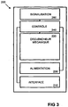
- An alarm trigger device 200 for the security system is shown schematically on the figure 3 .
- the alarm triggering device in this embodiment is a manual trigger 200.
- This manual trigger includes a wireless interface 210 for connecting the manual trigger 200 to the security system central station 100 by means of the wireless link.
- a mechanical release 220 such as a push button having one or two positions of stable equilibrium to allow a user to manually trigger an alarm in the event of a predetermined event for example a fire
- a power supply 230 to power the manual release 200
- a control processor 240 constituting a fault detector 240 for detecting a malfunction of the trigger
- a signaling device 250 capable of signaling, at the level of the manual trigger 200, the fault of the operation of the manual trigger detected by the fault detector 240.
- the signaling device 250 may be arranged to signal at the level of the manual trigger 200 a signal of alarm when the mechanical trigger 220 is triggered in case of malfunction.
- an alarm device may be provided in the manual trigger 200 to generate an alarm signal in the event of a malfunction when a test button is actuated.
- the fault detector 240 is connected to the wireless interface 210 and to the battery 230. It is configured to detect a lack of wireless communication with the monitoring station 100 and to detect a fault. supply to the manual release from the battery 230.
- the fault detector 240 may be configured to measure the intensity of the radio signal received from the control unit via the wireless interface 50 and to compare it with a predetermined intensity threshold. In another embodiment, the fault detector 240 may be configured to measure the signal-to-noise ratio of the radio signal received from the control unit via the wireless interface 50 to compare it with a threshold of the signal ratio. on predetermined noise. In a particular embodiment, the fault detector may be configured to send a test signal to the central monitoring station 100 and wait for a response signal from the central unit 100 to verify the wireless link 50. A lack of response or receiving a low intensity response signal may indicate a wireless link fault. In other embodiments, communication radio signals can be transmitted from the central monitoring station 100 to the manual trigger on a regular basis. The absence of detection of these signals or the detection of signals having a low intensity can trigger the signaling means 250 to generate a malfunction alarm signal.
- the device described above also makes it easier to install the triggering devices. Indeed, once the plant is installed, it is possible to position the trigger devices at positions such that the signaling means are not malfunction alarm. For example, if they are arranged to emit a sound signal in the form of pulses at repetition frequencies which are all the lower as the quality of the radio link deteriorates, the person who inserts the triggering device has information directly noticeable. Of course, it would be possible to transmit the pulses at repetition frequencies which are all the greater as the quality of the radio link deteriorates.
- the fault detector 240 may be configured to measure the level of energy remaining in the cell 230 to compare it with a predetermined threshold. The measurement of a level of energy lower than said threshold indicates a malfunction of power supply.
- the signaling means 250 are configured to generate different signaling depending on the malfunction.
- the signaling means may comprise a first warning indicator dedicated to a communication fault and a second warning indicator dedicated to a power failure.
- the transmission of a signal visible from the first indicator indicates a communication fault and the emission of a signal visible from the second indicator indicates a power failure.
- a single indicator can be configured to emit different colors depending on the malfunction or to flash at different frequencies depending on the malfunction.
- an audible signal may be emitted by the signaling means to warn of a malfunction. Different sounds may be emitted depending on the detected operating fault or the transmission frequency of these sounds may vary depending on the malfunction or these sounds may be transmitted as pulses at fault-dependent repetition frequencies. Operating.
- the signaling device 250 When the fault detector 240 detects a communication break with the monitoring station 100 or a decrease in the intensity of the communication signal below the reference threshold, the signaling device 250 is implemented in such a way as to signal a communication failure and / or a power failure at the manual trip 200. Thus, a person in the vicinity of the manual release 200 will be alerted to the malfunction status of the manual release 200. This will allow the replacement of the battery of 230 power supply or manual trigger repair.
- the alarm trigger device is equipped with a presence detector and the signaling device would be operated only in the presence of people in the vicinity of the trigger.
- the presence detector may include an infrared ray detector from an associated infrared ray emitter. The absence or reduction of infrared rays from the infrared emitter would indicate the presence of one or more persons.
- the presence detector may comprise an infrared ray detector emitted by the person or persons in the vicinity of the trigger because of their temperature. The appearance of these infrared rays would indicate the presence of one or more people.
- the presence detector may be integrated in the alarm triggering device or may be a separate device from the alarm triggering device and associated with the alarm triggering device.
- the presence detector may include a finger-sensitive element, such as a push button, or finger-touch, such as a touch key.
- an alarm signal can also be transmitted to the central monitoring station 100 to directly warn of the malfunction of the manual release 200 .
- fire detection systems have been described more particularly in the embodiments presented.
- the present invention also applies to other security systems.
- the radio link between a trigger and the central can be done using intermediate triggers, which can allow the radio link even if the distance between the trigger actuated and the central is too large to allow a direct connection.
Description
La présente invention est relative à un dispositif de déclenchement d'alarme pour un système de sécurité (détection d'incendie, détection d'intrusion, détection d'anomalies de fonctionnement d'installations techniques, ...) ; et à un système de sécurité (détection d'incendie, détection d'intrusion, d'anomalies de fonctionnement d'installations techniques,...). Elle s'applique en particulier à la détection d'incendie ou d'intrusion dans des bâtiments publics ou privés, résidentiels, industriels, commerciaux ou de loisir ou à la détection d'anomalies de fonctionnement d'installations techniques. Par la suite on désignera par alarmes techniques la détection d'anomalies de fonctionnement d'installations techniques et par événement prédéterminé un incendie, une intrusion ou une anomalie de fonctionnement d'installations techniques ou similaires.The present invention relates to an alarm triggering device for a security system (fire detection, intrusion detection, detection of malfunctions of technical installations, etc.); and a security system (fire detection, intrusion detection, malfunctions of technical installations, ...). It applies in particular to the detection of fire or intrusion in public or private buildings, residential, industrial, commercial or leisure or the detection of malfunctions of technical installations. Thereafter the technical alarms will be designated as the detection of malfunctions of technical installations and, by a predetermined event, a fire, an intrusion or a malfunction of technical installations or the like.
Dans le cas de la détection d'incendie, un système de détection d'incendie comprend une centrale électronique de surveillance et un réseau de détection en communication avec la centrale électronique incluant un ou plusieurs dispositifs de déclenchement d'alarme ou points de détection d'incendie. Ces dispositifs de déclenchement d'alarme ou points de détection peuvent comprendre des détecteurs d'incendie automatiques aptes à capter un phénomène représentatif d'un incendie et des détecteurs d'incendie manuels (déclencheurs manuels) qui sont aptes à être actionnés par une personne découvrant une situation d'incendie. Les dispositifs de déclenchement d'alarme sont en général répartis dans la zone ou les zones à surveiller et reliés à la centrale de surveillance. La centrale électronique permet de surveiller la zone ou les zones à surveiller au moyen des dispositifs de déclenchement d'alarme et d'émettre une alarme lorsqu'un incendie est détecté.In the case of fire detection, a fire detection system includes an electronic monitoring unit and a detection network in communication with the electronic control unit including one or more alarm triggering devices or detection points. fire. These alarm-triggering devices or detection points may include automatic fire detectors capable of capturing a phenomenon representative of a fire and manual fire detectors (manual triggers) which are able to be actuated by a person discovering a fire situation. The alarm triggering devices are generally distributed in the zone or zones to be monitored and connected to the central monitoring station. The electronic control unit monitors the area (s) to be monitored using the alarm triggers and emits an alarm when a fire is detected.
Les dispositifs de déclenchement d'alarme sont reliés à la centrale de surveillance de manière à permettre un échange d'informations entre la centrale et lesdits dispositifs de déclenchement d'alarme afin que la centrale soit informée de l'état de chaque élément du réseau de détection, et le cas échéant de les commander.The alarm triggering devices are connected to the central monitoring station so as to allow an exchange of information between the central unit and the said alarm triggering devices so that the central unit is informed of the state of each element of the network of alarms. detection, and if necessary to order them.
On connaît des systèmes de détection d'incendie dans lesquels les dispositifs de déclenchement d'alarme sont reliés à la centrale au moyen d'une liaison sans fil. Afin de permettre une surveillance fiable et sûre, il est important que la liaison entre chaque dispositif de déclenchement d'alarme et la centrale soit de bonne qualité pour permettre les échanges d'informations. Cependant la qualité de la liaison peut être dégradée à cause d'une perte de puissance électrique du dispositif de déclenchement d'alarme ou de la présence d'obstacles sur le chemin de communication radio entre ledit dispositif de déclenchement d'alarme et la centrale, par exemple. Cela peut mener à une rupture de communication entre les deux éléments.Fire detection systems are known in which the alarm release devices are connected to the control unit by means of a wireless link. In order to allow reliable and safe monitoring, it is important that the link between each alarm triggering device and the control panel is of good quality to allow the exchange of information. However, the quality of the link may be degraded because of a loss of electrical power of the alarm triggering device or the presence of obstacles on the radio communication path between said alarm triggering device and the central station, for example. This can lead to a break in communication between the two elements.
De plus, la communication sans fil pour un dispositif de déclenchement d'alarme exige une consommation élevée de courant, ce qui peut rapidement épuiser la source d'alimentation.In addition, wireless communication for an alarm triggering device requires high power consumption, which can quickly deplete the power source.
Un défaut d'alimentation ou de communication radio peut être très dangereux lorsqu'un incendie se produit puisque le dispositif de déclenchement d'alarme ne serait pas capable de communiquer avec la centrale de surveillance pour l'alerter du déclenchement d'alarme. Dans le cas où le dispositif de déclenchement d'alarme est un déclencheur manuel, en cas de défaut tel qu'évoqué ci-dessus, la personne qui actionne ledit déclencheur manuel ne serait pas informée qu'il y a un défaut de fonctionnement du déclencheur et qu'ainsi l'alarme ne serait pas transmise à la centrale du système de détection d'incendie.A power failure or radio communication can be very dangerous when a fire occurs because the alarm triggering device would not be able to communicate with the central monitoring station to alert it of the alarm triggering. In the case where the alarm trigger device is a manual release, in case of a defect as mentioned above, the person who actuates said manual release would not be informed that there is a malfunction of the trigger and thus the alarm would not be transmitted to the central fire detection system.
Les mêmes inconvénients que ceux qui viennent d'être décrits se retrouvent lorsque l'on considère un système de détection d'intrusion ou un système de détection d'anomalies de fonctionnement d'installations techniques.The same disadvantages as those just described are found when considering an intrusion detection system or a malfunction detection system of technical installations.
La présente invention vise à remédier à tout ou partie des inconvénients précités. Ellle est définie par les revendications.The present invention aims to remedy all or part of the aforementioned drawbacks. It is defined by the claims.
Dans ce qui suit, on va décrire quelques modes de réalisations préférés de l'invention en se référant aux figures ci-annexées d'une manière bien entendu non limitative.
- La
figure 1 représente schématiquement des éléments d'un système de sécurité selon un premier mode de réalisation de l'invention. - La
figure 2A représente schématiquement une centrale de surveillance selon un premier mode de réalisation de l'invention. - La
figure 2B représente schématiquement la face avant d'un coffret de centrale de surveillance selon un premier mode de réalisation de l'invention. - La
figure 3 représente schématiquement un dispositif de déclenchement d'alarme selon un premier mode de réalisation de l'invention.
- The
figure 1 schematically represents elements of a security system according to a first embodiment of the invention. - The
Figure 2A schematically represents a central monitoring according to a first embodiment of the invention. - The
Figure 2B schematically represents the front face of a control panel box according to a first embodiment of the invention. - The
figure 3 schematically represents an alarm triggering device according to a first embodiment of the invention.
Un système de sécurité 10 selon un premier mode de l'invention est représenté schématiquement sur la
Dans le mode de réalisation illustré sur la
La centrale de surveillance 100 est configurée de manière connue en soi pour détecter l'apparition d'une alarme de l'un quelconque des dispositifs de déclenchement d'alarme 200-1..200-n, signaler la condition d'alarme par des moyens visuels et/ou sonores et pour commander lesdits dispositifs de déclenchement d'alarme 200-1..200-n. Les moyens de communication 104 comportent une interface sans fil incluant un dispositif de réception et de transmission des signaux radio, muni d'une antenne pour permettre à la centrale de communiquer avec les dispositifs de déclenchement d'alarme 200-1...200-n au moyen des liaisons sans fil 50-1...50-n.The
On observe en
L'écran d'affichage 116 permet à l'unité centrale d'afficher des messages visuels à destination d'un utilisateur de la centrale de surveillance et/ou d'un membre du service de maintenance de ce dispositif. En particulier, l'écran d'affichage 116 est adapté pour afficher un indicateur d'alarme.The
Le coffret 110 peut être équipé de manière connue en soi de moyens permettant une liaison par fil téléphonique, par Internet ou autre vers des moyens centraux de surveillance et de contrôle.The
Les dispositifs de déclenchement d'alarme 200-1...200n incluent des déclencheurs automatiques comportant des détecteurs d'événement prédéterminé et des déclencheurs manuels. Les détecteurs d'événement prédéterminé automatiques sont aptes à capter un phénomène représentatif d'événement prédéterminé, par exemple dans le cas d'un incendie de la fumée ou des flammes. Ces détecteurs peuvent être configurés pour détecter une variation d'une grandeur physique ou chimique, par exemple et de manière non limitative, une température, une présence de particules de fumée ou une composition de l'air et, lorsque cette variation répond à des critères prédéterminés par exemple des critères d'amplitude, de dérivée ou de dérivée seconde, ledit détecteur transmet un signal représentatif d'une détection d'événement prédéterminé à destination de la centrale de surveillance 100 par l'intermédiaire des liaisons sans fil 50-n. Les déclencheurs automatiques déclenchent une alarme en réponse à la détection d'un phénomène représentatif d'un évènement prédéterminé. Les déclencheurs manuels quant à eux sont aptes à être actionnés manuellement par une personne découvrant une situation d'événement prédéterminé, par exemple un incendie. En réponse au déclenchement, un signal d'alarme est transmis à destination de la centrale de surveillance 100. Dans certains modes de réalisation de l'invention un signal d'alarme peut être signalé au niveau du dispositif de déclenchement d'alarme.Alarm triggering devices 200-1 ... 200n include automatic triggers having predetermined event detectors and manual triggers. The predetermined automatic event detectors are capable of capturing a representative phenomenon of a predetermined event, for example in the case of a fire of smoke or flames. These detectors can be configured to detect a variation of a physical or chemical quantity, for example and without limitation, a temperature, a presence of smoke particles or a composition of the air and, when this variation meets criteria. predetermined, for example amplitude, derivative or second derivative criteria, said detector transmits a signal representative of a predetermined event detection to the
Un dispositif de déclenchement d'alarme 200 pour le système de sécurité, selon un premier mode de réalisation de l'invention, est représenté schématiquement sur la
Le détecteur de défaut 240 est raccordé à l'interface sans fil 210 et à la pile 230. Il est configuré de manière à permettre la détection d'une absence de communication sans fil avec la centrale de surveillance 100 et à détecter un défaut d'alimentation au déclencheur manuel à partir de la pile 230.The
À cet effet, le détecteur de défaut 240 peut être configuré de sorte à mesurer l'intensité du signal radio reçu de la centrale par l'intermédiaire de l'interface sans fil 50 et de la comparer avec un seuil d'intensité prédéterminée. Dans un autre mode de réalisation le détecteur de défaut 240 peut être configuré de sorte à mesurer le rapport signal sur bruit du signal radio reçu de la centrale par l'intermédiaire de l'interface sans fil 50 pour le comparer avec un seuil du rapport signal sur bruit prédéterminé. Dans un mode de réalisation particulier le détecteur de défaut peut être configuré pour envoyer un signal de test à la centrale de surveillance 100 et attendre un signal de réponse en provenance de la centrale 100 afin de vérifier la liaison sans fil 50. Une absence de réponse ou la réception d'un signal de réponse d'une intensité faible peut indiquer un défaut de liaison sans fil. Dans d'autres modes de réalisation, des signaux radio de communication peuvent être transmis de la centrale de surveillance 100 vers le déclencheur manuel d'une façon régulière. L'absence de détection de ces signaux ou la détection de signaux ayant une intensité faible peut déclencher les moyens de signalisation 250 pour générer un signal d'alarme de dysfonctionnement.For this purpose, the
Il est à noter que le dispositif décrit ci-dessus permet en outre de faciliter l'installation des dispositifs de déclenchement. En effet une fois la centrale installée, il est possible de positionner les dispositifs de déclenchement à des positions telles que les moyens de signalisation ne soient pas en alarme de dysfonctionnement. Par exemple s'ils sont agencés pour émettre un signal sonore sous forme d'impulsions à des fréquences de répétition d'autant plus faibles que la qualité de la liaison radio se dégrade, la personne qui assure la pose du dispositif de déclenchement a une information directement perceptible. Bien entendu il serait possible d'émettre les impulsions à des fréquences de répétition d'autant plus grandes que la qualité de la liaison radio se dégrade.It should be noted that the device described above also makes it easier to install the triggering devices. Indeed, once the plant is installed, it is possible to position the trigger devices at positions such that the signaling means are not malfunction alarm. For example, if they are arranged to emit a sound signal in the form of pulses at repetition frequencies which are all the lower as the quality of the radio link deteriorates, the person who inserts the triggering device has information directly noticeable. Of course, it would be possible to transmit the pulses at repetition frequencies which are all the greater as the quality of the radio link deteriorates.
De la même façon, le détecteur de défaut 240 peut être configuré de sorte à mesurer le niveau d'énergie restant dans la pile 230 pour le comparer avec un seuil prédéterminé. La mesure d'un niveau d'énergie inférieur au dit seuil indique un défaut de fonctionnement d'alimentation.In the same way, the
Dans ce mode de réalisation, les moyens de signalisation 250 sont configurés pour générer des signalisations différentes en fonction du défaut de fonctionnement. Par exemple, les moyens de signalisation peuvent comprendre un premier voyant d'avertissement dédié à un défaut de communication et un deuxième voyant d'avertissement dédié à un défaut d'alimentation. Ainsi, l'émission d'un signal visible du premier voyant indique un défaut de communication et l'émission d'un signal visible du deuxième voyant indique un défaut d'alimentation. Dans des variantes, un seul voyant peut être configuré pour émettre des couleurs différentes en fonction du défaut de fonctionnement ou pour clignoter à des fréquences différentes en fonction du défaut de fonctionnement. Dans d'autres variantes, un signal sonore peut être émis par les moyens de signalisation pour avertir d'un défaut du fonctionnement. Des sons différents peuvent être émis en fonction du défaut du fonctionnement détecté ou la fréquence d'émission de ces sons peut varier en fonction du défaut de fonctionnement ou encore ces sons peuvent être émis sous forme d'impulsions à des fréquences de répétition dépendantes du défaut de fonctionnement.In this embodiment, the signaling means 250 are configured to generate different signaling depending on the malfunction. For example, the signaling means may comprise a first warning indicator dedicated to a communication fault and a second warning indicator dedicated to a power failure. Thus, the transmission of a signal visible from the first indicator indicates a communication fault and the emission of a signal visible from the second indicator indicates a power failure. In variants, a single indicator can be configured to emit different colors depending on the malfunction or to flash at different frequencies depending on the malfunction. In other variants, an audible signal may be emitted by the signaling means to warn of a malfunction. Different sounds may be emitted depending on the detected operating fault or the transmission frequency of these sounds may vary depending on the malfunction or these sounds may be transmitted as pulses at fault-dependent repetition frequencies. Operating.
Lorsque le détecteur de défaut 240 détecte une coupure de communication avec la centrale de surveillance 100 ou une diminution de l'intensité du signal de communication en-dessous du seuil de référence, le dispositif de signalisation 250 est mis en oeuvre de manière à signaler un défaut de communication et/ou un défaut d'alimentation au niveau du déclencheur manuel 200. Ainsi, une personne au voisinage du déclencheur manuel 200 sera alertée de l'état de dysfonctionnement du déclencheur manuel 200. Cela permettra le remplacement de la pile d'alimentation 230 ou la réparation du déclencheur manuel.When the
Pour éviter la mise en oeuvre du dispositif de signalisation en l'absence d'une personne dans son voisinage, ce qui pourrait consommer le peu d'énergie restant dans la pile, c'est dans le cas où la personne voudrait déclencher une alarme d'événement prédéterminé qu'elle serait informée que le déclencheur ne fonctionne pas et elle pourrait alors déclencher l'alarme par l'intermédiaire d'un autre déclencheur manuel ou autrement.To avoid the implementation of the signaling device in the absence of a person in his vicinity, which could consume the little energy remaining in the battery, it is in the case where the person would like to trigger an alarm of predetermined event that she would be informed that the trigger did not work and she could then trigger the alarm via another manual trigger or otherwise.
Selon l'invention, et également pour éviter la mise en oeuvre du dispositif de signalisation en l'absence d'une personne dans son voisinage, ce qui pourrait consommer le peu d'énergie restant dans la pile, le dispositif de déclenchement d'alarme est équipé d'un détecteur de présence et le dispositif de signalisation ne serait actionné qu'en présence de personnes au voisinage du déclencheur. Par exemple, le détecteur de présence peut comprendre un détecteur des rayons infrarouges en provenance d'un émetteur de rayons infrarouges associé. L'absence ou la diminution des rayons infrarouges en provenance de l'émetteur de rayons infrarouge indiqueraient la présence d'une ou plusieurs personnes. Dans un second exemple le détecteur de présence peut comprendre un détecteur des rayons infrarouges émis par la ou les personnes au voisinage du déclencheur du fait de leur température. L'apparition de ces rayons infrarouges indiquerait la présence d'une ou plusieurs personnes. Le détecteur de présence peut être intégré dans le dispositif de déclenchement d'alarme ou peut être un dispositif distinct du dispositif de déclenchement d'alarme et associé au dispositif de déclenchement d'alarme. Dans un troisième exemple le détecteur de présence peut comprendre un élément sensible à la pression d'un doigt, tel qu'un bouton poussoir, ou au toucher par un doigt, tel qu'une touche tactile.According to the invention, and also to avoid the implementation of the signaling device in the absence of a person in its vicinity, which could consume the little energy remaining in the battery, the alarm trigger device is equipped with a presence detector and the signaling device would be operated only in the presence of people in the vicinity of the trigger. For example, the presence detector may include an infrared ray detector from an associated infrared ray emitter. The absence or reduction of infrared rays from the infrared emitter would indicate the presence of one or more persons. In a second example, the presence detector may comprise an infrared ray detector emitted by the person or persons in the vicinity of the trigger because of their temperature. The appearance of these infrared rays would indicate the presence of one or more people. The presence detector may be integrated in the alarm triggering device or may be a separate device from the alarm triggering device and associated with the alarm triggering device. In a third example, the presence detector may include a finger-sensitive element, such as a push button, or finger-touch, such as a touch key.
Dans certains modes de réalisation, lorsqu'il y a encore un moyen de communiquer avec la centrale de surveillance, un signal d'alarme peut également être transmis à la centrale de surveillance 100 pour l'avertir directement du défaut de fonctionnement du déclencheur manuel 200.In some embodiments, when there is still a means of communicating with the central monitoring station, an alarm signal can also be transmitted to the
Dans ce qui précède, et comme cela a déjà été indiqué, on a plus particulièrement décrit dans les modes de réalisation présentés des systèmes de détection d'incendie. Bien entendu la présente invention s'applique également aux autres systèmes de sécurité.In the foregoing, and as already indicated, fire detection systems have been described more particularly in the embodiments presented. Of course, the present invention also applies to other security systems.
Comme il va de soi et comme il résulte d'ailleurs déjà de ce qui précède, l'invention ne se limite nullement à ceux des modes d'applications et de réalisations qui ont été plus spécialement envisagés ; elle en embrasse au contraire toutes les variantes sans pour autant sortir du cadre de l'invention tel que défini par les revendications.It goes without saying and as it follows already from the above, the invention is not limited to those modes of applications and achievements that have been more specifically considered; it encompasses all variants without departing from the scope of the invention as defined by the claims.
Par exemple, bien que les modes de réalisations aient été décrits avec un déclencheur manuel, il sera compris que dans d'autres modes de réalisation de l'invention, les détecteurs d'événement prédéterminé automatiques peuvent être utilisés.For example, although the embodiments have been described with a manual trigger, it will be understood that in other embodiments of the invention, the automatic predetermined event detectors can be used.
Dans une autre variante de l'invention, la liaison radio entre un déclencheur et la centrale peut se faire en utilisant des déclencheurs intermédiaires, ce qui peut permettre la liaison radio même si la distance entre le déclencheur actionné et la centrale est trop grande pour permettre une liaison directe.In another variant of the invention, the radio link between a trigger and the central can be done using intermediate triggers, which can allow the radio link even if the distance between the trigger actuated and the central is too large to allow a direct connection.
Claims (14)
- Alarm triggering device (200) for a security system (10), the alarm triggering device (200) comprising
an interface (210) arranged so as to connect the alarm triggering device (200) to a control unit of the security system (100) by means of a wireless connection (50);
triggering means (220) to trigger an alarm in case a predefined event is detected;
supply means (230) to enable the alarm triggering device (200) to be supplied with electricity from a power supply;
means of detecting the presence of at least one person in the vicinity of the alarm triggering device (200)
fault detection means (240) to detect an operating fault in the alarm triggering device; and
signaling means (250) to signal the operating fault in the alarm triggering device (200) at the location of the alarm triggering device (200), wherein the detection means (240) are arranged so as to detect a communications fault between the alarm triggering device (200) and the control unit (100) by means of the wireless connection (50) and the signaling means (250) are arranged to signal said communications fault by a visible or audible alarm when the presence of at least one person is detected. - Alarm triggering device (200) according to claim 1, wherein the detection means (240) are arranged so as to detect a fault in the power supply to the alarm triggering device (200) from the power source and the signaling means (250) are arranged to signal said power supply fault.
- Device according to either one of claims 1 or 2, wherein the fault detection means (240) are arranged so as to measure a parameter representative of the reception quality of a predefined radio verification signal coming from the security system control unit.
- Device according to claim 3, wherein the fault detection means (240) are arranged to measure the signal-to-noise ratio or the intensity of the predefined radio verification signal.
- Device according to any one of the claims 1 to 4, wherein the signaling means (250) are arranged so as to generate different signals depending on the type and/or magnitude of the operating fault.
- Alarm triggering device according to any one of claims 1 to 5, comprising in addition means of signaling the operating fault to the control unit (100).
- Alarm triggering device (200) according to any one of claims 1 to 6, wherein the triggering means (220) are arranged to allow a user to trigger an alarm manually if a predefined event occurs.
- Alarm triggering device (200) according to claim 7, wherein the signaling means (250) are arranged to signal the operating fault when a user manually triggers the alarm.
- Alarm triggering device according to claim 8, wherein the means of detecting persons comprise a detector of infrared rays from an infrared ray emitter associated with or from a person.
- Alarm triggering device according to any one of claims 1 to 9, comprising in addition a test triggering element sensitive to the pressure of a press by a person to trigger an operating fault detection.
- Alarm triggering device according to any one of claims 1 to 10, wherein the triggering means (220) to trigger an alarm in case a predefined event is detected are configured to detect a predefined event consisting in an intrusion and/or an operational malfunction in a technical facility.
- Alarm triggering device according to any one of claims 1 to 11, wherein the triggering means (220) to trigger an alarm in case a predefined event is detected are configured to detect a predefined event consisting in a fire.
- Alarm triggering device (200) according to claim 12, wherein the triggering means comprise a fire detector able to detect a phenomenon representative of a fire and automatically trigger an alarm in response to the detection of said phenomenon.
- Security system comprising at least one alarm triggering device (200) according to any one of claims 1 to 13 and a central monitoring station (100) able to be connected by means of a wireless connection (50) to said at least one alarm triggering device (200).
Priority Applications (1)
| Application Number | Priority Date | Filing Date | Title |
|---|---|---|---|
| PL12717337T PL2678845T3 (en) | 2011-03-31 | 2012-03-29 | Alarm triggering device for a security system |
Applications Claiming Priority (2)
| Application Number | Priority Date | Filing Date | Title |
|---|---|---|---|
| FR1100946A FR2973544B1 (en) | 2011-03-31 | 2011-03-31 | ALARM TRIGGER DEVICE FOR A SECURITY SYSTEM |
| PCT/FR2012/000114 WO2012131190A2 (en) | 2011-03-31 | 2012-03-29 | Alarm triggering device for a security system |
Publications (3)
| Publication Number | Publication Date |
|---|---|
| EP2678845A2 EP2678845A2 (en) | 2014-01-01 |
| EP2678845B1 EP2678845B1 (en) | 2015-05-20 |
| EP2678845B2 true EP2678845B2 (en) | 2019-05-22 |
Family
ID=46017904
Family Applications (1)
| Application Number | Title | Priority Date | Filing Date |
|---|---|---|---|
| EP12717337.5A Active EP2678845B2 (en) | 2011-03-31 | 2012-03-29 | Alarm triggering device for a security system |
Country Status (6)
| Country | Link |
|---|---|
| US (1) | US9467358B2 (en) |
| EP (1) | EP2678845B2 (en) |
| ES (1) | ES2545518T3 (en) |
| FR (1) | FR2973544B1 (en) |
| PL (1) | PL2678845T3 (en) |
| WO (1) | WO2012131190A2 (en) |
Citations (5)
| Publication number | Priority date | Publication date | Assignee | Title |
|---|---|---|---|---|
| DE19539312A1 (en) † | 1995-10-23 | 1997-04-24 | Grundig Emv | Procedure for increasing the transmission security in radio alarm systems |
| DE69914784T2 (en) † | 1998-10-06 | 2004-09-23 | General Electric Company | WIRELESS HOUSE FIRE AND SAFETY ALARM SYSTEM |
| GB2423397A (en) † | 2005-02-18 | 2006-08-23 | Locca Tech Ltd | Wireless smoke alarm system |
| EP1742390A2 (en) † | 2005-07-05 | 2007-01-10 | Robert Bosch GmbH | Method of installing a wireless security system |
| US20070171051A1 (en) † | 2006-01-23 | 2007-07-26 | Kazuhiro Kashiwagi | Wireless sensor system |
Family Cites Families (60)
| Publication number | Priority date | Publication date | Assignee | Title |
|---|---|---|---|---|
| US2987712A (en) * | 1957-09-12 | 1961-06-06 | Itt | Fault alarm system |
| ES415997A1 (en) * | 1973-06-16 | 1976-02-16 | Arteche Instr | Fault detection and signaling system |
| US3909722A (en) * | 1973-06-22 | 1975-09-30 | Jbh Electronic Systems Inc | Variable frequency communication system |
| US4064507A (en) * | 1975-05-29 | 1977-12-20 | Westinghouse Electric Corporation | Noise generator circuit for a security system |
| US4141007A (en) * | 1977-04-22 | 1979-02-20 | Kavasilios Michael A | Central alarm conditioning detecting and alerting system |
| US4191947A (en) * | 1978-09-06 | 1980-03-04 | Gte Sylvania Incorporated | Intrusion alarm system |
| DE4020175C2 (en) * | 1990-06-25 | 1994-01-20 | Waldemar Marinitsch | Device for failsafe testing of an infrared sensor arrangement |
| US5822373A (en) * | 1995-08-17 | 1998-10-13 | Pittway Corporation | Method and apparatus for optimization of wireless communications |
| US8210047B2 (en) | 1996-01-23 | 2012-07-03 | En-Gauge, Inc. | Remote fire extinguisher station inspection |
| US5936524A (en) * | 1996-05-02 | 1999-08-10 | Visonic Ltd. | Intrusion detector |
| US6346983B1 (en) * | 1998-01-29 | 2002-02-12 | Aleksandr L. Yufa | Methods and wireless communicating particle counting and measuring apparatus |
| US6157307A (en) * | 1998-03-17 | 2000-12-05 | Hardin; Kenneth J. | Floodwater detection and warning device |
| NZ501475A (en) * | 1999-12-02 | 2002-08-28 | Tru Test Ltd | Electric fence current pulse amplitude indicated by tone output |
| US20050264427A1 (en) * | 2000-03-03 | 2005-12-01 | The Gov. Of The Usa As Repres. By The Secretary Of The Dept. Of Health And Human Services | Electrical injury protection system |
| US6809642B1 (en) * | 2000-04-10 | 2004-10-26 | Robert Harry Brenner | Evacuation warning system for computer local area networks |
| CA2405636C (en) * | 2000-04-11 | 2011-08-23 | Recherche 2000 Inc. | Method and apparatus for acquisition, monitoring, display and diagnosis of operational parameters of electrolysers |
| US6492901B1 (en) * | 2000-05-10 | 2002-12-10 | Westinghouse Electric Company Llc | Alarm management system |
| JP3575419B2 (en) * | 2000-10-24 | 2004-10-13 | 日本電気株式会社 | Apparatus state control circuit and apparatus state control method |
| US6944679B2 (en) * | 2000-12-22 | 2005-09-13 | Microsoft Corp. | Context-aware systems and methods, location-aware systems and methods, context-aware vehicles and methods of operating the same, and location-aware vehicles and methods of operating the same |
| US7081815B2 (en) | 2001-08-23 | 2006-07-25 | Battelle Memorial Institute | Radio frequency security system, method for a building facility or the like, and apparatus and methods for remotely monitoring the status of fire extinguishers |
| US20030179149A1 (en) * | 2001-11-26 | 2003-09-25 | Schlumberger Electricity, Inc. | Embedded antenna apparatus for utility metering applications |
| JP2005522164A (en) * | 2002-03-28 | 2005-07-21 | ロバートショー コントロールズ カンパニー | Energy management system and method |
| US6744366B2 (en) * | 2002-04-04 | 2004-06-01 | Hoton How | Method and apparatus of obtaining security tag operation using local magnetic marker |
| US7266729B2 (en) * | 2002-12-27 | 2007-09-04 | Intel Corporation | Managing a wireless platform |
| DE10321204B3 (en) * | 2003-05-12 | 2005-01-13 | Siemens Ag | Method and device for monitoring the function of radio transmission paths in a hazard detection system |
| JP4512324B2 (en) * | 2003-05-21 | 2010-07-28 | ティアック株式会社 | Semiconductor laser drive device and optical disk device |
| US7132954B2 (en) * | 2003-07-07 | 2006-11-07 | Automatic Pool Covers, Inc. | Self monitoring pool cover system |
| GB0318054D0 (en) * | 2003-08-01 | 2003-09-03 | Euronet Security Ltd | Remote alarm apparatus |
| US7239236B1 (en) | 2003-08-16 | 2007-07-03 | Britton Rick A | Wireless sensors for alarm system operations |
| WO2006044751A2 (en) * | 2004-10-18 | 2006-04-27 | Walter Kidde Portable Equipment, Inc. | Frequency communications scheme in life safety devices |
| US7508314B2 (en) * | 2004-10-18 | 2009-03-24 | Walter Kidde Portable Equipment, Inc. | Low battery warning silencing in life safety devices |
| US20090199855A1 (en) * | 2004-11-01 | 2009-08-13 | Davenport James M | System and method for conserving oxygen delivery while maintaining saturation |
| GB0503452D0 (en) * | 2005-02-18 | 2005-03-30 | Locca Tech Ltd | Wireless remote controllable fire and smoke alarm system |
| WO2006127440A2 (en) * | 2005-05-20 | 2006-11-30 | Gard Dog, Llc | Child safety alarm |
| US7639147B2 (en) * | 2005-12-29 | 2009-12-29 | Honeywell International Inc. | System and method of acoustic detection and location of audible alarm devices |
| US7904396B2 (en) * | 2006-03-28 | 2011-03-08 | The United States Of America As Represented By The Administrator Of The National Aeronautics And Space Administration | Systems, methods and apparatus for quiesence of autonomic safety devices with self action |
| US7746222B2 (en) * | 2006-10-23 | 2010-06-29 | Robert Bosch Gmbh | Method and apparatus for installing a wireless security system |
| WO2008066753A1 (en) * | 2006-11-22 | 2008-06-05 | Solidica, Inc. | Diagnostic and telematic system |
| US20090027229A1 (en) * | 2007-07-11 | 2009-01-29 | Fortson Frederick O | Smart armor |
| US7719433B1 (en) * | 2007-07-23 | 2010-05-18 | United Services Automobile Association (Usaa) | Extended smoke alarm system |
| US7760359B2 (en) * | 2007-12-10 | 2010-07-20 | Honeywell International Inc. | Beam detector distance measurement |
| US8879218B2 (en) * | 2007-12-14 | 2014-11-04 | True-Safe Technologies, Inc. | Arc fault circuit interrupter, systems, apparatus and methods of detecting and interrupting electrical faults |
| US7881678B2 (en) | 2007-12-20 | 2011-02-01 | Johnson Controls Technology Company | Wireless device for physical coupling to another object |
| US8254858B2 (en) * | 2007-12-21 | 2012-08-28 | Hewlett-Packard Development Company, L.P. | Techniques to manage power based on motion detection |
| US8981927B2 (en) | 2008-02-13 | 2015-03-17 | En-Gauge, Inc. | Object Tracking with emergency equipment |
| US8046625B2 (en) * | 2008-02-22 | 2011-10-25 | Hill-Rom Services, Inc. | Distributed fault tolerant architecture for a healthcare communication system |
| US8081001B2 (en) * | 2008-03-27 | 2011-12-20 | Siemens Industry, Inc. | Device, system and method for automatic self-test for a ground fault interrupter |
| US20110111700A1 (en) | 2008-04-29 | 2011-05-12 | Jamie Hackett | Wireless control system using variable power dual modulation transceivers |
| US8284065B2 (en) * | 2008-10-03 | 2012-10-09 | Universal Security Instruments, Inc. | Dynamic alarm sensitivity adjustment and auto-calibrating smoke detection |
| US8054188B2 (en) * | 2009-01-05 | 2011-11-08 | Utc Fire & Security Americas Corporation, Inc. | Carbon monoxide detector, system and method for signaling a carbon monoxide sensor end-of-life condition |
| US8416096B2 (en) * | 2009-04-02 | 2013-04-09 | Utc Fire & Security Americas Corporation, Inc. | System and method of controlling indicators of a property monitoring system |
| US8638211B2 (en) | 2009-04-30 | 2014-01-28 | Icontrol Networks, Inc. | Configurable controller and interface for home SMA, phone and multimedia |
| US20100302045A1 (en) * | 2009-05-29 | 2010-12-02 | Andrew Foster | Interface for a fire alarm system |
| JP5051214B2 (en) * | 2009-12-25 | 2012-10-17 | 株式会社デンソー | In-vehicle failure detection device |
| NO2541994T3 (en) | 2010-02-23 | 2018-02-24 | ||
| US8558889B2 (en) * | 2010-04-26 | 2013-10-15 | Sensormatic Electronics, LLC | Method and system for security system tampering detection |
| US8700252B2 (en) | 2010-07-27 | 2014-04-15 | Ford Global Technologies, Llc | Apparatus, methods, and systems for testing connected services in a vehicle |
| US11750414B2 (en) * | 2010-12-16 | 2023-09-05 | Icontrol Networks, Inc. | Bidirectional security sensor communication for a premises security system |
| US8508359B2 (en) * | 2010-12-17 | 2013-08-13 | Simplexgrinnell Lp | Method and system for wireless configuration, control, and status reporting of devices in a fire alarm system |
| US8446107B2 (en) * | 2011-02-23 | 2013-05-21 | Zilog, Inc. | Smart clamp |
-
2011
- 2011-03-31 FR FR1100946A patent/FR2973544B1/en not_active Expired - Fee Related
-
2012
- 2012-03-29 ES ES12717337.5T patent/ES2545518T3/en active Active
- 2012-03-29 US US14/007,806 patent/US9467358B2/en not_active Expired - Fee Related
- 2012-03-29 EP EP12717337.5A patent/EP2678845B2/en active Active
- 2012-03-29 PL PL12717337T patent/PL2678845T3/en unknown
- 2012-03-29 WO PCT/FR2012/000114 patent/WO2012131190A2/en active Application Filing
Patent Citations (5)
| Publication number | Priority date | Publication date | Assignee | Title |
|---|---|---|---|---|
| DE19539312A1 (en) † | 1995-10-23 | 1997-04-24 | Grundig Emv | Procedure for increasing the transmission security in radio alarm systems |
| DE69914784T2 (en) † | 1998-10-06 | 2004-09-23 | General Electric Company | WIRELESS HOUSE FIRE AND SAFETY ALARM SYSTEM |
| GB2423397A (en) † | 2005-02-18 | 2006-08-23 | Locca Tech Ltd | Wireless smoke alarm system |
| EP1742390A2 (en) † | 2005-07-05 | 2007-01-10 | Robert Bosch GmbH | Method of installing a wireless security system |
| US20070171051A1 (en) † | 2006-01-23 | 2007-07-26 | Kazuhiro Kashiwagi | Wireless sensor system |
Also Published As
| Publication number | Publication date |
|---|---|
| US9467358B2 (en) | 2016-10-11 |
| WO2012131190A3 (en) | 2012-12-20 |
| US20140016480A1 (en) | 2014-01-16 |
| FR2973544A1 (en) | 2012-10-05 |
| ES2545518T3 (en) | 2015-09-11 |
| EP2678845A2 (en) | 2014-01-01 |
| WO2012131190A2 (en) | 2012-10-04 |
| PL2678845T3 (en) | 2015-11-30 |
| FR2973544B1 (en) | 2013-11-15 |
| EP2678845B1 (en) | 2015-05-20 |
Similar Documents
| Publication | Publication Date | Title |
|---|---|---|
| US20090289787A1 (en) | Residential security cluster with associated alarm interconnects | |
| EP2320397B1 (en) | Fire sensor and method for detecting fire | |
| US20130154823A1 (en) | Alarm Detection and Notification System | |
| FR2893743A1 (en) | METHOD AND DEVICE FOR DETECTING FIRE IN A DRILL | |
| FR2977966A1 (en) | EXTINCTOR IDENTIFICATION METHOD AND EXTINCTOR IDENTIFICATION DEVICE | |
| EP2731681A1 (en) | Fire extinguishing device for a security system | |
| EP2678846B2 (en) | Alarm triggering device for a security system | |
| EP2678844B1 (en) | Alarm triggering device for a security system and method for installing an alarm triggering device | |
| EP2678845B2 (en) | Alarm triggering device for a security system | |
| EP0681723B1 (en) | Tamperproof radio anti-jamming device for trespass monitoring systems | |
| GB2549261A (en) | Alarm and environment monitoring system | |
| EP2553946A2 (en) | Method and device for loudspeaker control | |
| FR3012966A1 (en) | DEVICE AND SECURITY SYSTEM, PORTABLE EXTINGUISHER, EXTINCTOR MEDIUM, AND METHOD OF DEPLOYING A SECURITY SYSTEM | |
| US11350262B1 (en) | Self-contained disaster condition monitoring system | |
| AU2019203389A1 (en) | Smoke alarm | |
| EP3979152A1 (en) | System for monitoring equipment, associated devices and methods | |
| EP3475931B1 (en) | Method for operating an alarm system comprising a remote device | |
| EP1296300B1 (en) | Interactive method, device and system for operating a smoke producing anti-intrusion apparatus | |
| FR2966963A1 (en) | Fire protection installation for use in electric network of building, has monitoring units detecting isolation or continuity fault of line and communication bus, and signaling unit signaling fault status of bus and/or line to alarm center | |
| FR2575571A1 (en) | Anti-intrusion safety installation | |
| WO2015114170A1 (en) | Device for detecting fire or gas leakage and system for securing premises comprising said device | |
| FR2964231A1 (en) | Safety installation for use in building i.e. public receiving place, has alarm managing units connected to remote control circuit of autonomous safety lighting blocks such that units are connected between each other via circuit of blocks | |
| WO2015140453A1 (en) | Alarm device for an underground worksite | |
| FR2958107A1 (en) | Loudspeaker's operating state control method for safety system used to e.g. evacuate person during fire, involves determining loudspeaker state based on measured electrical resistance on electrical connection over which impulse is emitted | |
| FR2963463A1 (en) | Method for signaling e.g. fire alert status in public building, involves controlling pulsed mode operation of light source by remote control case and circuit to generate emission of pulsed light signals from autonomous lighting blocks |
Legal Events
| Date | Code | Title | Description |
|---|---|---|---|
| PUAI | Public reference made under article 153(3) epc to a published international application that has entered the european phase |
Free format text: ORIGINAL CODE: 0009012 |
|
| 17P | Request for examination filed |
Effective date: 20130926 |
|
| AK | Designated contracting states |
Kind code of ref document: A2 Designated state(s): AL AT BE BG CH CY CZ DE DK EE ES FI FR GB GR HR HU IE IS IT LI LT LU LV MC MK MT NL NO PL PT RO RS SE SI SK SM TR |
|
| GRAP | Despatch of communication of intention to grant a patent |
Free format text: ORIGINAL CODE: EPIDOSNIGR1 |
|
| INTG | Intention to grant announced |
Effective date: 20141202 |
|
| GRAS | Grant fee paid |
Free format text: ORIGINAL CODE: EPIDOSNIGR3 |
|
| GRAA | (expected) grant |
Free format text: ORIGINAL CODE: 0009210 |
|
| AK | Designated contracting states |
Kind code of ref document: B1 Designated state(s): AL AT BE BG CH CY CZ DE DK EE ES FI FR GB GR HR HU IE IS IT LI LT LU LV MC MK MT NL NO PL PT RO RS SE SI SK SM TR |
|
| DAX | Request for extension of the european patent (deleted) | ||
| REG | Reference to a national code |
Ref country code: GB Ref legal event code: FG4D Free format text: NOT ENGLISH |
|
| REG | Reference to a national code |
Ref country code: CH Ref legal event code: EP |
|
| REG | Reference to a national code |
Ref country code: AT Ref legal event code: REF Ref document number: 728079 Country of ref document: AT Kind code of ref document: T Effective date: 20150615 |
|
| REG | Reference to a national code |
Ref country code: IE Ref legal event code: FG4D Free format text: LANGUAGE OF EP DOCUMENT: FRENCH |
|
| REG | Reference to a national code |
Ref country code: DE Ref legal event code: R096 Ref document number: 602012007435 Country of ref document: DE |
|
| REG | Reference to a national code |
Ref country code: ES Ref legal event code: FG2A Ref document number: 2545518 Country of ref document: ES Kind code of ref document: T3 Effective date: 20150911 |
|
| REG | Reference to a national code |
Ref country code: AT Ref legal event code: MK05 Ref document number: 728079 Country of ref document: AT Kind code of ref document: T Effective date: 20150520 |
|
| REG | Reference to a national code |
Ref country code: LT Ref legal event code: MG4D |
|
| REG | Reference to a national code |
Ref country code: NL Ref legal event code: MP Effective date: 20150520 |
|
| PG25 | Lapsed in a contracting state [announced via postgrant information from national office to epo] |
Ref country code: NO Free format text: LAPSE BECAUSE OF FAILURE TO SUBMIT A TRANSLATION OF THE DESCRIPTION OR TO PAY THE FEE WITHIN THE PRESCRIBED TIME-LIMIT Effective date: 20150820 Ref country code: PT Free format text: LAPSE BECAUSE OF FAILURE TO SUBMIT A TRANSLATION OF THE DESCRIPTION OR TO PAY THE FEE WITHIN THE PRESCRIBED TIME-LIMIT Effective date: 20150921 Ref country code: HR Free format text: LAPSE BECAUSE OF FAILURE TO SUBMIT A TRANSLATION OF THE DESCRIPTION OR TO PAY THE FEE WITHIN THE PRESCRIBED TIME-LIMIT Effective date: 20150520 Ref country code: FI Free format text: LAPSE BECAUSE OF FAILURE TO SUBMIT A TRANSLATION OF THE DESCRIPTION OR TO PAY THE FEE WITHIN THE PRESCRIBED TIME-LIMIT Effective date: 20150520 Ref country code: LT Free format text: LAPSE BECAUSE OF FAILURE TO SUBMIT A TRANSLATION OF THE DESCRIPTION OR TO PAY THE FEE WITHIN THE PRESCRIBED TIME-LIMIT Effective date: 20150520 |
|
| PG25 | Lapsed in a contracting state [announced via postgrant information from national office to epo] |
Ref country code: IS Free format text: LAPSE BECAUSE OF FAILURE TO SUBMIT A TRANSLATION OF THE DESCRIPTION OR TO PAY THE FEE WITHIN THE PRESCRIBED TIME-LIMIT Effective date: 20150920 Ref country code: GR Free format text: LAPSE BECAUSE OF FAILURE TO SUBMIT A TRANSLATION OF THE DESCRIPTION OR TO PAY THE FEE WITHIN THE PRESCRIBED TIME-LIMIT Effective date: 20150821 Ref country code: BG Free format text: LAPSE BECAUSE OF FAILURE TO SUBMIT A TRANSLATION OF THE DESCRIPTION OR TO PAY THE FEE WITHIN THE PRESCRIBED TIME-LIMIT Effective date: 20150820 Ref country code: LV Free format text: LAPSE BECAUSE OF FAILURE TO SUBMIT A TRANSLATION OF THE DESCRIPTION OR TO PAY THE FEE WITHIN THE PRESCRIBED TIME-LIMIT Effective date: 20150520 Ref country code: AT Free format text: LAPSE BECAUSE OF FAILURE TO SUBMIT A TRANSLATION OF THE DESCRIPTION OR TO PAY THE FEE WITHIN THE PRESCRIBED TIME-LIMIT Effective date: 20150520 Ref country code: RS Free format text: LAPSE BECAUSE OF FAILURE TO SUBMIT A TRANSLATION OF THE DESCRIPTION OR TO PAY THE FEE WITHIN THE PRESCRIBED TIME-LIMIT Effective date: 20150520 |
|
| REG | Reference to a national code |
Ref country code: PL Ref legal event code: T3 |
|
| PG25 | Lapsed in a contracting state [announced via postgrant information from national office to epo] |
Ref country code: EE Free format text: LAPSE BECAUSE OF FAILURE TO SUBMIT A TRANSLATION OF THE DESCRIPTION OR TO PAY THE FEE WITHIN THE PRESCRIBED TIME-LIMIT Effective date: 20150520 Ref country code: DK Free format text: LAPSE BECAUSE OF FAILURE TO SUBMIT A TRANSLATION OF THE DESCRIPTION OR TO PAY THE FEE WITHIN THE PRESCRIBED TIME-LIMIT Effective date: 20150520 |
|
| REG | Reference to a national code |
Ref country code: DE Ref legal event code: R026 Ref document number: 602012007435 Country of ref document: DE |
|
| PLBI | Opposition filed |
Free format text: ORIGINAL CODE: 0009260 |
|
| PG25 | Lapsed in a contracting state [announced via postgrant information from national office to epo] |
Ref country code: SK Free format text: LAPSE BECAUSE OF FAILURE TO SUBMIT A TRANSLATION OF THE DESCRIPTION OR TO PAY THE FEE WITHIN THE PRESCRIBED TIME-LIMIT Effective date: 20150520 Ref country code: RO Free format text: LAPSE BECAUSE OF NON-PAYMENT OF DUE FEES Effective date: 20150520 Ref country code: CZ Free format text: LAPSE BECAUSE OF FAILURE TO SUBMIT A TRANSLATION OF THE DESCRIPTION OR TO PAY THE FEE WITHIN THE PRESCRIBED TIME-LIMIT Effective date: 20150520 |
|
| 26 | Opposition filed |
Opponent name: GEZE GMBH Effective date: 20160222 |
|
| PLAX | Notice of opposition and request to file observation + time limit sent |
Free format text: ORIGINAL CODE: EPIDOSNOBS2 |
|
| PG25 | Lapsed in a contracting state [announced via postgrant information from national office to epo] |
Ref country code: SI Free format text: LAPSE BECAUSE OF FAILURE TO SUBMIT A TRANSLATION OF THE DESCRIPTION OR TO PAY THE FEE WITHIN THE PRESCRIBED TIME-LIMIT Effective date: 20150520 |
|
| REG | Reference to a national code |
Ref country code: FR Ref legal event code: PLFP Year of fee payment: 5 |
|
| PLBB | Reply of patent proprietor to notice(s) of opposition received |
Free format text: ORIGINAL CODE: EPIDOSNOBS3 |
|
| PG25 | Lapsed in a contracting state [announced via postgrant information from national office to epo] |
Ref country code: MC Free format text: LAPSE BECAUSE OF FAILURE TO SUBMIT A TRANSLATION OF THE DESCRIPTION OR TO PAY THE FEE WITHIN THE PRESCRIBED TIME-LIMIT Effective date: 20150520 Ref country code: LU Free format text: LAPSE BECAUSE OF FAILURE TO SUBMIT A TRANSLATION OF THE DESCRIPTION OR TO PAY THE FEE WITHIN THE PRESCRIBED TIME-LIMIT Effective date: 20160329 |
|
| REG | Reference to a national code |
Ref country code: IE Ref legal event code: MM4A |
|
| PG25 | Lapsed in a contracting state [announced via postgrant information from national office to epo] |
Ref country code: IE Free format text: LAPSE BECAUSE OF NON-PAYMENT OF DUE FEES Effective date: 20160329 |
|
| REG | Reference to a national code |
Ref country code: FR Ref legal event code: PLFP Year of fee payment: 6 |
|
| PGFP | Annual fee paid to national office [announced via postgrant information from national office to epo] |
Ref country code: CH Payment date: 20170327 Year of fee payment: 6 |
|
| PGFP | Annual fee paid to national office [announced via postgrant information from national office to epo] |
Ref country code: GB Payment date: 20170327 Year of fee payment: 6 Ref country code: BE Payment date: 20170327 Year of fee payment: 6 Ref country code: PL Payment date: 20170306 Year of fee payment: 6 |
|
| PG25 | Lapsed in a contracting state [announced via postgrant information from national office to epo] |
Ref country code: SE Free format text: LAPSE BECAUSE OF FAILURE TO SUBMIT A TRANSLATION OF THE DESCRIPTION OR TO PAY THE FEE WITHIN THE PRESCRIBED TIME-LIMIT Effective date: 20150520 Ref country code: NL Free format text: LAPSE BECAUSE OF FAILURE TO SUBMIT A TRANSLATION OF THE DESCRIPTION OR TO PAY THE FEE WITHIN THE PRESCRIBED TIME-LIMIT Effective date: 20150520 |
|
| PGFP | Annual fee paid to national office [announced via postgrant information from national office to epo] |
Ref country code: IT Payment date: 20170324 Year of fee payment: 6 Ref country code: TR Payment date: 20170309 Year of fee payment: 6 |
|
| PGFP | Annual fee paid to national office [announced via postgrant information from national office to epo] |
Ref country code: DE Payment date: 20170329 Year of fee payment: 6 |
|
| PG25 | Lapsed in a contracting state [announced via postgrant information from national office to epo] |
Ref country code: MT Free format text: LAPSE BECAUSE OF FAILURE TO SUBMIT A TRANSLATION OF THE DESCRIPTION OR TO PAY THE FEE WITHIN THE PRESCRIBED TIME-LIMIT Effective date: 20150520 |
|
| PGFP | Annual fee paid to national office [announced via postgrant information from national office to epo] |
Ref country code: ES Payment date: 20170328 Year of fee payment: 6 |
|
| APBM | Appeal reference recorded |
Free format text: ORIGINAL CODE: EPIDOSNREFNO |
|
| APBP | Date of receipt of notice of appeal recorded |
Free format text: ORIGINAL CODE: EPIDOSNNOA2O |
|
| APAH | Appeal reference modified |
Free format text: ORIGINAL CODE: EPIDOSCREFNO |
|
| APBQ | Date of receipt of statement of grounds of appeal recorded |
Free format text: ORIGINAL CODE: EPIDOSNNOA3O |
|
| REG | Reference to a national code |
Ref country code: FR Ref legal event code: PLFP Year of fee payment: 7 |
|
| PG25 | Lapsed in a contracting state [announced via postgrant information from national office to epo] |
Ref country code: SM Free format text: LAPSE BECAUSE OF FAILURE TO SUBMIT A TRANSLATION OF THE DESCRIPTION OR TO PAY THE FEE WITHIN THE PRESCRIBED TIME-LIMIT Effective date: 20150520 Ref country code: CY Free format text: LAPSE BECAUSE OF FAILURE TO SUBMIT A TRANSLATION OF THE DESCRIPTION OR TO PAY THE FEE WITHIN THE PRESCRIBED TIME-LIMIT Effective date: 20150520 Ref country code: HU Free format text: LAPSE BECAUSE OF FAILURE TO SUBMIT A TRANSLATION OF THE DESCRIPTION OR TO PAY THE FEE WITHIN THE PRESCRIBED TIME-LIMIT; INVALID AB INITIO Effective date: 20120329 |
|
| PG25 | Lapsed in a contracting state [announced via postgrant information from national office to epo] |
Ref country code: MK Free format text: LAPSE BECAUSE OF FAILURE TO SUBMIT A TRANSLATION OF THE DESCRIPTION OR TO PAY THE FEE WITHIN THE PRESCRIBED TIME-LIMIT Effective date: 20150520 |
|
| REG | Reference to a national code |
Ref country code: DE Ref legal event code: R119 Ref document number: 602012007435 Country of ref document: DE |
|
| PG25 | Lapsed in a contracting state [announced via postgrant information from national office to epo] |
Ref country code: AL Free format text: LAPSE BECAUSE OF FAILURE TO SUBMIT A TRANSLATION OF THE DESCRIPTION OR TO PAY THE FEE WITHIN THE PRESCRIBED TIME-LIMIT Effective date: 20150520 |
|
| REG | Reference to a national code |
Ref country code: CH Ref legal event code: PL |
|
| GBPC | Gb: european patent ceased through non-payment of renewal fee |
Effective date: 20180329 |
|
| APBU | Appeal procedure closed |
Free format text: ORIGINAL CODE: EPIDOSNNOA9O |
|
| REG | Reference to a national code |
Ref country code: BE Ref legal event code: MM Effective date: 20180331 |
|
| PG25 | Lapsed in a contracting state [announced via postgrant information from national office to epo] |
Ref country code: DE Free format text: LAPSE BECAUSE OF NON-PAYMENT OF DUE FEES Effective date: 20181002 |
|
| PG25 | Lapsed in a contracting state [announced via postgrant information from national office to epo] |
Ref country code: BE Free format text: LAPSE BECAUSE OF NON-PAYMENT OF DUE FEES Effective date: 20180331 Ref country code: CH Free format text: LAPSE BECAUSE OF NON-PAYMENT OF DUE FEES Effective date: 20180331 Ref country code: IT Free format text: LAPSE BECAUSE OF NON-PAYMENT OF DUE FEES Effective date: 20180329 Ref country code: GB Free format text: LAPSE BECAUSE OF NON-PAYMENT OF DUE FEES Effective date: 20180329 Ref country code: LI Free format text: LAPSE BECAUSE OF NON-PAYMENT OF DUE FEES Effective date: 20180331 |
|
| PUAH | Patent maintained in amended form |
Free format text: ORIGINAL CODE: 0009272 |
|
| STAA | Information on the status of an ep patent application or granted ep patent |
Free format text: STATUS: PATENT MAINTAINED AS AMENDED |
|
| 27A | Patent maintained in amended form |
Effective date: 20190522 |
|
| AK | Designated contracting states |
Kind code of ref document: B2 Designated state(s): AL AT BE BG CH CY CZ DE DK EE ES FI FR GB GR HR HU IE IS IT LI LT LU LV MC MK MT NL NO PL PT RO RS SE SI SK SM TR |
|
| REG | Reference to a national code |
Ref country code: DE Ref legal event code: R102 Ref document number: 602012007435 Country of ref document: DE |
|
| PG25 | Lapsed in a contracting state [announced via postgrant information from national office to epo] |
Ref country code: ES Free format text: LAPSE BECAUSE OF FAILURE TO SUBMIT A TRANSLATION OF THE DESCRIPTION OR TO PAY THE FEE WITHIN THE PRESCRIBED TIME-LIMIT Effective date: 20190522 |
|
| PG25 | Lapsed in a contracting state [announced via postgrant information from national office to epo] |
Ref country code: PL Free format text: LAPSE BECAUSE OF NON-PAYMENT OF DUE FEES Effective date: 20180329 |
|
| REG | Reference to a national code |
Ref country code: ES Ref legal event code: FD2A Effective date: 20200420 |
|
| PG25 | Lapsed in a contracting state [announced via postgrant information from national office to epo] |
Ref country code: ES Free format text: LAPSE BECAUSE OF FAILURE TO SUBMIT A TRANSLATION OF THE DESCRIPTION OR TO PAY THE FEE WITHIN THE PRESCRIBED TIME-LIMIT Effective date: 20180330 |
|
| PG25 | Lapsed in a contracting state [announced via postgrant information from national office to epo] |
Ref country code: TR Free format text: LAPSE BECAUSE OF NON-PAYMENT OF DUE FEES Effective date: 20180329 |
|
| PGFP | Annual fee paid to national office [announced via postgrant information from national office to epo] |
Ref country code: FR Payment date: 20230330 Year of fee payment: 12 |