EP2678657B1 - Aseptic sampling system - Google Patents
Aseptic sampling system Download PDFInfo
- Publication number
- EP2678657B1 EP2678657B1 EP12713775.0A EP12713775A EP2678657B1 EP 2678657 B1 EP2678657 B1 EP 2678657B1 EP 12713775 A EP12713775 A EP 12713775A EP 2678657 B1 EP2678657 B1 EP 2678657B1
- Authority
- EP
- European Patent Office
- Prior art keywords
- sampler
- sterile
- assembly
- interface
- liquid
- Prior art date
- Legal status (The legal status is an assumption and is not a legal conclusion. Google has not performed a legal analysis and makes no representation as to the accuracy of the status listed.)
- Active
Links
Images







Classifications
-
- A—HUMAN NECESSITIES
- A61—MEDICAL OR VETERINARY SCIENCE; HYGIENE
- A61J—CONTAINERS SPECIALLY ADAPTED FOR MEDICAL OR PHARMACEUTICAL PURPOSES; DEVICES OR METHODS SPECIALLY ADAPTED FOR BRINGING PHARMACEUTICAL PRODUCTS INTO PARTICULAR PHYSICAL OR ADMINISTERING FORMS; DEVICES FOR ADMINISTERING FOOD OR MEDICINES ORALLY; BABY COMFORTERS; DEVICES FOR RECEIVING SPITTLE
- A61J1/00—Containers specially adapted for medical or pharmaceutical purposes
- A61J1/14—Details; Accessories therefor
- A61J1/20—Arrangements for transferring or mixing fluids, e.g. from vial to syringe
- A61J1/2096—Combination of a vial and a syringe for transferring or mixing their contents
-
- A—HUMAN NECESSITIES
- A61—MEDICAL OR VETERINARY SCIENCE; HYGIENE
- A61J—CONTAINERS SPECIALLY ADAPTED FOR MEDICAL OR PHARMACEUTICAL PURPOSES; DEVICES OR METHODS SPECIALLY ADAPTED FOR BRINGING PHARMACEUTICAL PRODUCTS INTO PARTICULAR PHYSICAL OR ADMINISTERING FORMS; DEVICES FOR ADMINISTERING FOOD OR MEDICINES ORALLY; BABY COMFORTERS; DEVICES FOR RECEIVING SPITTLE
- A61J1/00—Containers specially adapted for medical or pharmaceutical purposes
- A61J1/05—Containers specially adapted for medical or pharmaceutical purposes for collecting, storing or administering blood, plasma or medical fluids ; Infusion or perfusion containers
- A61J1/10—Bag-type containers
- A61J1/12—Bag-type containers with means for holding samples of contents
-
- A—HUMAN NECESSITIES
- A61—MEDICAL OR VETERINARY SCIENCE; HYGIENE
- A61J—CONTAINERS SPECIALLY ADAPTED FOR MEDICAL OR PHARMACEUTICAL PURPOSES; DEVICES OR METHODS SPECIALLY ADAPTED FOR BRINGING PHARMACEUTICAL PRODUCTS INTO PARTICULAR PHYSICAL OR ADMINISTERING FORMS; DEVICES FOR ADMINISTERING FOOD OR MEDICINES ORALLY; BABY COMFORTERS; DEVICES FOR RECEIVING SPITTLE
- A61J1/00—Containers specially adapted for medical or pharmaceutical purposes
- A61J1/14—Details; Accessories therefor
- A61J1/1475—Inlet or outlet ports
-
- A—HUMAN NECESSITIES
- A61—MEDICAL OR VETERINARY SCIENCE; HYGIENE
- A61M—DEVICES FOR INTRODUCING MEDIA INTO, OR ONTO, THE BODY; DEVICES FOR TRANSDUCING BODY MEDIA OR FOR TAKING MEDIA FROM THE BODY; DEVICES FOR PRODUCING OR ENDING SLEEP OR STUPOR
- A61M39/00—Tubes, tube connectors, tube couplings, valves, access sites or the like, specially adapted for medical use
- A61M39/10—Tube connectors; Tube couplings
- A61M39/14—Tube connectors; Tube couplings for connecting tubes having sealed ends
-
- A—HUMAN NECESSITIES
- A61—MEDICAL OR VETERINARY SCIENCE; HYGIENE
- A61M—DEVICES FOR INTRODUCING MEDIA INTO, OR ONTO, THE BODY; DEVICES FOR TRANSDUCING BODY MEDIA OR FOR TAKING MEDIA FROM THE BODY; DEVICES FOR PRODUCING OR ENDING SLEEP OR STUPOR
- A61M39/00—Tubes, tube connectors, tube couplings, valves, access sites or the like, specially adapted for medical use
- A61M39/10—Tube connectors; Tube couplings
- A61M39/16—Tube connectors; Tube couplings having provision for disinfection or sterilisation
- A61M39/18—Methods or apparatus for making the connection under sterile conditions, i.e. sterile docking
-
- B—PERFORMING OPERATIONS; TRANSPORTING
- B01—PHYSICAL OR CHEMICAL PROCESSES OR APPARATUS IN GENERAL
- B01L—CHEMICAL OR PHYSICAL LABORATORY APPARATUS FOR GENERAL USE
- B01L1/00—Enclosures; Chambers
- B01L1/02—Air-pressure chambers; Air-locks therefor
-
- B—PERFORMING OPERATIONS; TRANSPORTING
- B01—PHYSICAL OR CHEMICAL PROCESSES OR APPARATUS IN GENERAL
- B01L—CHEMICAL OR PHYSICAL LABORATORY APPARATUS FOR GENERAL USE
- B01L3/00—Containers or dishes for laboratory use, e.g. laboratory glassware; Droppers
- B01L3/56—Labware specially adapted for transferring fluids
- B01L3/563—Joints or fittings; Separable fluid transfer means to transfer fluids between at least two containers, e.g. connectors
-
- B—PERFORMING OPERATIONS; TRANSPORTING
- B65—CONVEYING; PACKING; STORING; HANDLING THIN OR FILAMENTARY MATERIAL
- B65D—CONTAINERS FOR STORAGE OR TRANSPORT OF ARTICLES OR MATERIALS, e.g. BAGS, BARRELS, BOTTLES, BOXES, CANS, CARTONS, CRATES, DRUMS, JARS, TANKS, HOPPERS, FORWARDING CONTAINERS; ACCESSORIES, CLOSURES, OR FITTINGS THEREFOR; PACKAGING ELEMENTS; PACKAGES
- B65D81/00—Containers, packaging elements, or packages, for contents presenting particular transport or storage problems, or adapted to be used for non-packaging purposes after removal of contents
- B65D81/32—Containers, packaging elements, or packages, for contents presenting particular transport or storage problems, or adapted to be used for non-packaging purposes after removal of contents for packaging two or more different materials which must be maintained separate prior to use in admixture
-
- G—PHYSICS
- G01—MEASURING; TESTING
- G01N—INVESTIGATING OR ANALYSING MATERIALS BY DETERMINING THEIR CHEMICAL OR PHYSICAL PROPERTIES
- G01N1/00—Sampling; Preparing specimens for investigation
- G01N1/02—Devices for withdrawing samples
- G01N1/10—Devices for withdrawing samples in the liquid or fluent state
-
- A—HUMAN NECESSITIES
- A61—MEDICAL OR VETERINARY SCIENCE; HYGIENE
- A61J—CONTAINERS SPECIALLY ADAPTED FOR MEDICAL OR PHARMACEUTICAL PURPOSES; DEVICES OR METHODS SPECIALLY ADAPTED FOR BRINGING PHARMACEUTICAL PRODUCTS INTO PARTICULAR PHYSICAL OR ADMINISTERING FORMS; DEVICES FOR ADMINISTERING FOOD OR MEDICINES ORALLY; BABY COMFORTERS; DEVICES FOR RECEIVING SPITTLE
- A61J1/00—Containers specially adapted for medical or pharmaceutical purposes
- A61J1/14—Details; Accessories therefor
- A61J1/1475—Inlet or outlet ports
- A61J1/1481—Inlet or outlet ports with connection retaining means, e.g. thread or snap-fit
-
- B—PERFORMING OPERATIONS; TRANSPORTING
- B01—PHYSICAL OR CHEMICAL PROCESSES OR APPARATUS IN GENERAL
- B01L—CHEMICAL OR PHYSICAL LABORATORY APPARATUS FOR GENERAL USE
- B01L2300/00—Additional constructional details
- B01L2300/06—Auxiliary integrated devices, integrated components
- B01L2300/0672—Integrated piercing tool
-
- B—PERFORMING OPERATIONS; TRANSPORTING
- B01—PHYSICAL OR CHEMICAL PROCESSES OR APPARATUS IN GENERAL
- B01L—CHEMICAL OR PHYSICAL LABORATORY APPARATUS FOR GENERAL USE
- B01L2400/00—Moving or stopping fluids
- B01L2400/04—Moving fluids with specific forces or mechanical means
- B01L2400/0475—Moving fluids with specific forces or mechanical means specific mechanical means and fluid pressure
- B01L2400/0478—Moving fluids with specific forces or mechanical means specific mechanical means and fluid pressure pistons
-
- B—PERFORMING OPERATIONS; TRANSPORTING
- B01—PHYSICAL OR CHEMICAL PROCESSES OR APPARATUS IN GENERAL
- B01L—CHEMICAL OR PHYSICAL LABORATORY APPARATUS FOR GENERAL USE
- B01L2400/00—Moving or stopping fluids
- B01L2400/06—Valves, specific forms thereof
- B01L2400/0633—Valves, specific forms thereof with moving parts
- B01L2400/0644—Valves, specific forms thereof with moving parts rotary valves
-
- G—PHYSICS
- G01—MEASURING; TESTING
- G01N—INVESTIGATING OR ANALYSING MATERIALS BY DETERMINING THEIR CHEMICAL OR PHYSICAL PROPERTIES
- G01N1/00—Sampling; Preparing specimens for investigation
- G01N1/02—Devices for withdrawing samples
- G01N1/10—Devices for withdrawing samples in the liquid or fluent state
- G01N2001/1031—Sampling from special places
- G01N2001/1037—Sampling from special places from an enclosure (hazardous waste, radioactive)
-
- G—PHYSICS
- G01—MEASURING; TESTING
- G01N—INVESTIGATING OR ANALYSING MATERIALS BY DETERMINING THEIR CHEMICAL OR PHYSICAL PROPERTIES
- G01N1/00—Sampling; Preparing specimens for investigation
- G01N1/02—Devices for withdrawing samples
- G01N1/10—Devices for withdrawing samples in the liquid or fluent state
- G01N1/20—Devices for withdrawing samples in the liquid or fluent state for flowing or falling materials
- G01N1/2035—Devices for withdrawing samples in the liquid or fluent state for flowing or falling materials by deviating part of a fluid stream, e.g. by drawing-off or tapping
- G01N2001/205—Devices for withdrawing samples in the liquid or fluent state for flowing or falling materials by deviating part of a fluid stream, e.g. by drawing-off or tapping using a valve
Definitions
- the present invention relates to an aseptic sampling system.
- industries such as bioprocessing and medical devices
- the sample and reservoir must not be contaminated by infectious agents that may be present in the atmosphere or on the surfaces outside the vessel.
- the present invention seeks to address the need for a sterile, ultra clean, fluidic connection to be made and broken, time after time, without contaminating any of the sample, any mechanism in the sampler that is in contact with the sample or reservoir, or the liquid in the reservoir itself.
- the name for this process is 'aseptic sampling'.
- US patent US 4,019,512 discloses a sterile connector assembly for moving blood component preparations through a fluid path established by engaged coupling elements within adjoined connectors.
- the open end of the connectors are closed by barrier membranes covered by protective members with adhesive film between the protective members and the barrier membranes.
- a pressure cap is mounted on one of the connectors to apply pressure to the adjoining connectors so that the membranes adhere to each other along a sterile surface which is substituted for the non-sterile protective member that is progressively pulled away.
- a penetrator member associated with one of the coupling elements penetrates the adjoined and adhered membranes so that an associated coupling element can engage the coupling element in the other connector.
- a sterile to sterile connection device comprising a connector and one or more coupling devices.
- the connector has a body portion which has two openings sealed from the environment so as to form a sterile environment within the connector. At least one of the openings being sealed from the environment by a sterile barrier plug.
- the connector also has a port capable to move within the body of the connector to at least an open and a closed position.
- the coupling device is formed of a body having two openings and a stem having a bore through at least a portion of the stem. The stem is contained within the body and capable of moving at least linearly through the body between a first and second stem position.
- One of the openings of the stem is sealed from the environment by a sterile barrier plug and the other is sealed to a presterilized component.
- the coupling device opening containing the sterile barrier plug is attached to either the inlet or outlet of the connector.
- the port contains a first opening and a second opening. Once the stem of the coupling device is moved inward toward the connector the sterile plugs are moved into the first opening of the port. The port then can be moved to its open position aligning its second opening with the openings of the connector body and the opening of the coupling device.
- WO 2010/121690 A1 relates to a valve for extracting a sample from a content of a tank. The sampling must occur without contamination.
- the valve comprises a stationary part securely connected to the tank, a mobile part releasably connected to the stationary part, and an actuating mechanism for switching between a base position and a switched position.
- the stationary part comprises a rotatably supported first partial body of a shutoff body substantially rotationally symmetrical about an axis.
- the mobile part comprises a rotatably supported second partial body of the shutoff body.
- the first partial body and/or the second partial body comprise a recess for receiving or conveying the sample.
- an aseptic sampling system as set out in claim 1.
- the system may be arranged such that the liquid connectors, in use, can subsequently be re-sealed, disconnected and separated.
- This invention provides a means of sampling where both the reservoir and sample remain free of contaminants that may be present in the atmosphere or on the surfaces of the sampling device and reservoir, and where many samples can be taken using the same equipment. Furthermore, the invention does not require external means of sterilization, for example, to inject high pressure steam or ethylene oxide. Rather the invention can be made from entirely disposable parts.
- the invention is an aseptic sampling system which comprises two mating assemblies shown schematically in Figure 1a .
- a sampler assembly 2 whose function is to withdraw or infuse a single sample, and an interface assembly 1 whose function is to provide the interface between the sampler assembly and the reservoir 38 to be sampled.
- the interface assembly 1 is usually retained with the reservoir 38 for the duration of an aseptic culture, and allows the repeated taking of samples through the use of one or more units of the sampler assembly 2.
- the sampler and interface assemblies 2, 1 together comprise the following parts. Firstly, an outer protective surface is provided, made up of a housing 8, 5 of each of the sampler and interface assemblies 11, 6. This outer protective surface makes a sterile enclosure by forming a barrier between the outer non-sterile atmosphere and the inner sterile atmosphere. Secondly, an air lock is provided that allows the joining of the sterile enclosure in the sampler and interface assemblies. Thirdly, a re-sealable liquid connection mechanism is provided that contains a connector in each of the sampler and interface assemblies 2, 1. At least one of the connectors is moved through the sterile enclosure and air lock to mate with the opposite connector in the liquid connection mechanism, without sliding on any surfaces that could be non-sterile.
- the liquid connection mechanism, sterile enclosure 18 , outer protective surface 5, 8 and air lock 11, 6 each are shown schematically and operated as shown in Figure 1 and described as follows.
- First the sampler assembly 2 is mated with the interface assembly 1 via the air lock 11, 6 ( Figure 1bi ).
- the air lock is opened, keeping the sterile enclosure 18 free of contamination of outside air.
- Second, the parts of the liquid connection mechanism 7, 9, 10 are joined within the sterile enclosure, and without sliding past surfaces 11, 6 of the air lock that may be non-sterile ( Figure 1bii ).
- the liquid connection mechanism 7,9,10 thus creates a sealed aseptic liquid flow path.
- a sample is then infused or withdrawn from the reservoir 38.
- the sampler and interface assemblies 2,1 are then separated by reversing the above procedure: first the liquid connection mechanism 7,9,10 is resealed and separated, and then the air lock is disengaged.
- the invention does not depend on particular forms of the component mechanisms.
- the novelty of this aseptic sampling system is the combination of a re-sealable liquid connection mechanism within a sterile enclosure 18, protected by an air lock 11,6 and an outer protective surface 5,8, so that the liquid connection can be made without the parts of the connection mechanism being exposed to outside air or being made to contact any surfaces that could be non-sterile, and that the liquid connection can be disconnected without contamination of the sampler or interface assemblies.
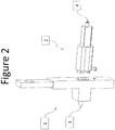
- the first embodiment as shown in Figure 2 , comprises two mechanical assemblies, an interface assembly 1 and a sampler assembly 2.
- the interface assembly provides a connector 3 to a reservoir and the sampler assembly provides a connector 4 to a sample vessel.
- Figure 2 shows female luer connectors for features 3 and 4.
- alternative embodiments would include barbed tube fittings, flanged sanitary fittings and flanged welded seals to connect to disposable bag bioreactors or disposable sampling bags.
- the interface 1 comprises a housing 5, shutter 6, and liquid valve 7.
- the connector to the reservoir is here a moulded pipe fitting 3 on the outside of the housing 5.
- the sampler 2 comprises a housing sheath 8, slider 9, inner cap 10 and outer cap 11.
- the shutter 6 is locked in position in the housing 5 by an interlock hook 15, which fits in an interlock aperture 16.
- Figure 3a shows the first embodiment before sampling.
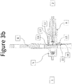
- the first step of sampling is shown in Figure 3b , where the sampler assembly 2 is pushed into a mating aperture 12 of the interface assembly 1.
- the outer cap 11 is then fully contained in a slot 13 of the shutter 6.
- an interlock protrusion 14 pushes the interlock hook 15 out of the interlock aperture 16. This allows the shutter 6 to slide vertically.
- the mating faces of the housing sheath 8 and housing 5 form an air-tight surface 17.
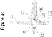
- the second step of sampling is shown in Figure 3c , where the shutter 6 is slid down. This moves the outer cap 11 away from the housing sheath 8 which has the effect of joining the sterile atmospheres in the sampler and interface assemblies 2,1 into a single sterile enclosure 18. At this point, the sterile enclosure 18 contains a direct path between the inner cap 10 and the liquid valve 7, while the outer cap 11 is fully stored away from the sterile enclosure 18.
- the third step of sampling is shown in Figure 3d .
- the slider 9 is now pushed towards the interface assembly so that the inner cap 10 mates with the liquid valve 7.
- the inner cap 10 contains a registration feature 19 that mates with an indentation on the liquid valve 7.
- the liquid valve 7 and the inner cap 10 form a continuous, sealing, cylindrical sliding surface 20 within the housing 5.
- the fourth step of sampling is shown in Figure 3e .
- the liquid valve 7 is rotated to the open position, such that the channel 22 now forms an open path between connector 3 from the reservoir and connector 4 to the sample vessel.
- the sample then flows through using the positive pressure of the reservoir or by applying suction to the sample vessel.
- the sampler assembly 2 is then removed.
- the movements are exactly opposite to the four steps above, leading to the disconnection of the sampler assembly 2 as shown in Figure 3a .
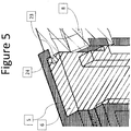
- tab features 23 may be provided on the housing sheath 8 to interlock with slots 24 in the shutter 6 so that the housing sheath 8 is held against the housing 5 in order to create an air seal between the two parts.
- Figure 6 shows the location of this air seal 17, which also includes a compliant material on at least one of the two mating surfaces.
- Similar tab features can be provided between components shown in Figure 3a : between the outer cap 11 and the housing sheath 8 and between the inner cap 10 and the slider 9.
- the sealing surfaces that are required for the preferred embodiment are shown in Figure 6 , and are: the surface 17 between the housing sheath 8 and the housing 5; the surface 25 between the housing sheath 8 and the slider 9; the surface 26 between the housing 5 and the shutter 6; the surface 27 between the housing 5 and the liquid valve 7; the surface 28 between the housing 5 and the inner cap 10; the surface 29 between the slider 9 and the inner cap 10; the surface 30 between the slider 9 and the liquid valve 7; the surface 31 between the inner cap 10 and the liquid valve 7; and the surface 32 between the housing sheath 8 and the outer cap 11.
- All sealing surfaces can be made by incorporation of a compliant material on at least one surface in each pair of the parts listed above or by incorporation of an additional, compliant sealing component such as an O-ring between the mating surfaces of pairs of parts.
- FIG. 6 A further optional feature which limits the range of movement between the slider 9 and the housing sheath 8 is shown in Figure 6 .
- a post 33 is attached to the slider 9 and runs within a groove 34 in the housing sheath 8. The post 33 ensures that the slider 9 cannot be pulled completely out of the housing sheath 8.
- a gas permeable vent 35 which is assembled into the housing 5 is also shown in Figure 6 .
- This vent 35 ensures that displacement of air caused by motion of internal parts does not generate an air pressure change within the sterile enclosure 18 described in Figure 3c .
- the vent 35 also ensures that changes in external air pressure do not generate a leakage of air between any of the sealing surfaces described previously.
- the vent is likely to be made of a filter material that excludes particles of greater than 0.22 ⁇ m in diameter.
- a variation on this embodiment is to use a different liquid connection mechanism such that the liquid valve 7 and inner cap 10 are replaced with alternative rotary valve mechanisms.
- Such valves are well known in the art.
- a further variation of this embodiment is a modification of the shutter 6 and housing 5, so that the shutter describes a circular sliding motion rather than a linear sliding motion.
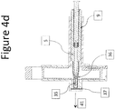
- FIG. 4a-4e A reference example not part of the invention is shown in Figures 4a-4e . The differences from the first embodiment are described below.
- the liquid connection mechanism in this case comprises a needle 35 and a pair of septa: a sample septum 36 and an interface septum 37.
- the interface septum 37 seals the interface assembly 1 from the reservoir 38.
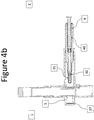
- Figures 4b to e show the sequence of operations to connect the sampler assembly 2 to the contents of the reservoir 38.
- the difference from the operational sequence of the first embodiment is that the liquid connection is now made by pushing the slider 9 directly through the position shown in Figure 4d to the position shown in Figure 4e as shown by the arrow 41.
- the needle 35 pierces both septa 36 and 37 and enters the reservoir 38 so that an aseptic liquid connection 39 is made.
- the septa 36 and 37 are both made of an elastomeric material that has the ability to reseal the pierced hole after removal of the needle.
- the interface septum 37 is designed to ensure that when the needle 35 is removed, the interface septum 37 can still maintain both a liquid and air tight seal, even after multiple piercings.
- One possible example of the sampling vessel is a syringe 40 as shown in Figure 4a .
Landscapes
- Health & Medical Sciences (AREA)
- Life Sciences & Earth Sciences (AREA)
- General Health & Medical Sciences (AREA)
- Chemical & Material Sciences (AREA)
- Veterinary Medicine (AREA)
- Public Health (AREA)
- Animal Behavior & Ethology (AREA)
- Heart & Thoracic Surgery (AREA)
- Clinical Laboratory Science (AREA)
- Chemical Kinetics & Catalysis (AREA)
- Hematology (AREA)
- Engineering & Computer Science (AREA)
- Pharmacology & Pharmacy (AREA)
- General Physics & Mathematics (AREA)
- Hydrology & Water Resources (AREA)
- Immunology (AREA)
- Pathology (AREA)
- Biochemistry (AREA)
- Analytical Chemistry (AREA)
- Pulmonology (AREA)
- Physics & Mathematics (AREA)
- Anesthesiology (AREA)
- Biomedical Technology (AREA)
- Epidemiology (AREA)
- Mechanical Engineering (AREA)
- Sampling And Sample Adjustment (AREA)
- Apparatus Associated With Microorganisms And Enzymes (AREA)
- External Artificial Organs (AREA)
Description
- The present invention relates to an aseptic sampling system. In industries such as bioprocessing and medical devices, there is an identified need for the aseptic and ultra clean removal and injection of multiple samples from a reservoir. The sample and reservoir must not be contaminated by infectious agents that may be present in the atmosphere or on the surfaces outside the vessel. The present invention seeks to address the need for a sterile, ultra clean, fluidic connection to be made and broken, time after time, without contaminating any of the sample, any mechanism in the sampler that is in contact with the sample or reservoir, or the liquid in the reservoir itself. The name for this process is 'aseptic sampling'.
- In the medical industry, for example in intravenous therapy, clean sampling is currently achieved to satisfaction using a single or dual rubber septum to ensure a minimum of dirt is transferred to any samples. One common method is to use a system where a needle is encased in one septum, and when pushed against a second septum, the needle pierces both, creating a fluid pathway with very low risk of contamination. However, when the two surfaces of the two septa touch, infectious particles can be trapped between them and be transferred to the needle as it pierces and slides through the join between the two septa. In many processes where a nutrient medium is incubated, a single infectious particle may destroy the product.
- US patent
US 4,019,512 discloses a sterile connector assembly for moving blood component preparations through a fluid path established by engaged coupling elements within adjoined connectors. The open end of the connectors are closed by barrier membranes covered by protective members with adhesive film between the protective members and the barrier membranes. A pressure cap is mounted on one of the connectors to apply pressure to the adjoining connectors so that the membranes adhere to each other along a sterile surface which is substituted for the non-sterile protective member that is progressively pulled away. A penetrator member associated with one of the coupling elements penetrates the adjoined and adhered membranes so that an associated coupling element can engage the coupling element in the other connector. - A sterile to sterile connection device is disclosed in
WO 2004/011077 A1 comprising a connector and one or more coupling devices. The connector has a body portion which has two openings sealed from the environment so as to form a sterile environment within the connector. At least one of the openings being sealed from the environment by a sterile barrier plug. The connector also has a port capable to move within the body of the connector to at least an open and a closed position. The coupling device is formed of a body having two openings and a stem having a bore through at least a portion of the stem. The stem is contained within the body and capable of moving at least linearly through the body between a first and second stem position. One of the openings of the stem is sealed from the environment by a sterile barrier plug and the other is sealed to a presterilized component. The coupling device opening containing the sterile barrier plug is attached to either the inlet or outlet of the connector. The port contains a first opening and a second opening. Once the stem of the coupling device is moved inward toward the connector the sterile plugs are moved into the first opening of the port. The port then can be moved to its open position aligning its second opening with the openings of the connector body and the opening of the coupling device. -
WO 2010/121690 A1 relates to a valve for extracting a sample from a content of a tank. The sampling must occur without contamination. To this end, according to this reference, the valve comprises a stationary part securely connected to the tank, a mobile part releasably connected to the stationary part, and an actuating mechanism for switching between a base position and a switched position. The stationary part comprises a rotatably supported first partial body of a shutoff body substantially rotationally symmetrical about an axis. The mobile part comprises a rotatably supported second partial body of the shutoff body. The first partial body and/or the second partial body comprise a recess for receiving or conveying the sample. - According to the present invention there is provided an aseptic sampling system as set out in
claim 1. - The system may be arranged such that the liquid connectors, in use, can subsequently be re-sealed, disconnected and separated.
- This invention provides a means of sampling where both the reservoir and sample remain free of contaminants that may be present in the atmosphere or on the surfaces of the
sampling device and reservoir, and where many samples can be taken using the same equipment. Furthermore, the invention does not require external means of sterilization, for example, to inject high pressure steam or ethylene oxide. Rather the invention can be made from entirely disposable parts. - Examples of the present invention will now be described with reference to the accompanying drawings, in which:
-
Figures 1a and 1b are schematic diagrams showing the principle of the invention; -
Figure 2 shows the outward form of the first preferred embodiment of the invention; -
Figures 3a to 3e show the mechanism and operation of the first preferred embodiment of the invention; -
Figures 4a to 4e show the mechanism and operation of a reference example not part of the invention; -
Figure 5 shows a cut-away detail of the first preferred embodiment of the invention; and -
Figure 6 shows further descriptions of the first preferred embodiment of the invention. - The invention is an aseptic sampling system which comprises two mating assemblies shown schematically in
Figure 1a . Asampler assembly 2 whose function is to withdraw or infuse a single sample, and aninterface assembly 1 whose function is to provide the interface between the sampler assembly and thereservoir 38 to be sampled. Theinterface assembly 1 is usually retained with thereservoir 38 for the duration of an aseptic culture, and allows the repeated taking of samples through the use of one or more units of thesampler assembly 2. - The sampler and interface assemblies 2, 1 together comprise the following parts. Firstly, an outer protective surface is provided, made up of a
housing interface assemblies interface assemblies - The liquid connection mechanism,
sterile enclosure 18 , outerprotective surface air lock Figure 1 and described as follows. First thesampler assembly 2 is mated with theinterface assembly 1 via theair lock 11, 6 (Figure 1bi ). The air lock is opened, keeping thesterile enclosure 18 free of contamination of outside air. Second, the parts of theliquid connection mechanism past surfaces
that may be non-sterile (Figure 1bii ). Theliquid connection mechanism reservoir 38. The sampler and interface assemblies 2,1 are then separated by reversing the above procedure: first theliquid connection mechanism - The invention does not depend on particular forms of the component mechanisms. The novelty of this aseptic sampling system is the combination of a re-sealable liquid connection mechanism within a
sterile enclosure 18, protected by anair lock protective surface reservoir 38, or the use of external sterilizing equipment. - The description below starts with to a first embodiment, but the invention is not limited to the geometry, mechanisms and motions described below.
- The first embodiment, as shown in
Figure 2 , comprises two mechanical assemblies, aninterface assembly 1 and asampler assembly 2. The interface assembly provides aconnector 3 to a reservoir and the sampler assembly provides aconnector 4 to a sample vessel.Figure 2 shows female luer connectors forfeatures - Each mechanical assembly comprises separate parts, detailed in the cross section diagram of
Figure 3 . Theinterface 1 comprises ahousing 5,shutter 6, andliquid valve 7. The connector to the reservoir is here a moulded pipe fitting 3 on the outside of thehousing 5. Thesampler 2 comprises ahousing sheath 8,slider 9,inner cap 10 andouter cap 11. Theshutter 6 is locked in position in thehousing 5 by aninterlock hook 15, which fits in aninterlock aperture 16. - The operating mechanism and sequence for the first embodiment is described with reference to
Figures 3a-3e .Figure 3a shows the first embodiment before sampling. - The first step of sampling is shown in
Figure 3b , where thesampler assembly 2 is pushed into amating aperture 12 of theinterface assembly 1. Theouter cap 11 is then fully contained in aslot 13 of theshutter 6. Simultaneously aninterlock protrusion 14 pushes theinterlock hook 15 out of theinterlock aperture 16. This allows theshutter 6 to slide vertically. The mating faces of thehousing sheath 8 andhousing 5 form an air-tight surface 17. - The second step of sampling is shown in
Figure 3c , where theshutter 6 is slid down. This moves theouter cap 11 away from thehousing sheath 8 which has the effect of joining the sterile atmospheres in the sampler andinterface assemblies sterile enclosure 18. At this point, thesterile enclosure 18 contains a direct path between theinner cap 10 and theliquid valve 7, while theouter cap 11 is fully stored away from thesterile enclosure 18. - The third step of sampling is shown in
Figure 3d . Theslider 9 is now pushed towards the interface assembly so that theinner cap 10 mates with theliquid valve 7. Theinner cap 10 contains aregistration feature 19 that mates with an indentation on theliquid valve 7. Theliquid valve 7 and theinner cap 10 form a continuous, sealing, cylindrical slidingsurface 20 within thehousing 5. - The fourth step of sampling is shown in
Figure 3e . Theliquid valve 7 is rotated to the open position, such that thechannel 22 now forms an open path betweenconnector 3 from the reservoir andconnector 4 to the sample vessel. The sample then flows through using the positive pressure of the reservoir or by applying suction to the sample vessel. - Having taken the sample, the
sampler assembly 2 is then removed. The movements are exactly opposite to the four steps above, leading to the disconnection of thesampler assembly 2 as shown inFigure 3a . - Additional details of the first embodiment are as follows.
- As shown in the cross-section illustration in
Figure 5 , tab features 23 may be provided on thehousing sheath 8 to interlock withslots 24 in theshutter 6 so that thehousing sheath 8 is held against thehousing 5 in order to create an air seal between the two parts.Figure 6 shows the location of thisair seal 17, which also includes a compliant material on at least one of the two mating surfaces.. Similar tab features can be provided between components shown inFigure 3a : between theouter cap 11 and thehousing sheath 8 and between theinner cap 10 and theslider 9. - The sealing surfaces that are required for the preferred embodiment are shown in
Figure 6 , and are: thesurface 17 between thehousing sheath 8 and thehousing 5; thesurface 25 between thehousing sheath 8 and theslider 9; thesurface 26 between thehousing 5 and theshutter 6; thesurface 27 between thehousing 5 and theliquid valve 7; thesurface 28 between thehousing 5 and theinner cap 10; thesurface 29 between theslider 9 and theinner cap 10; thesurface 30 between theslider 9 and theliquid valve 7; thesurface 31 between theinner cap 10 and theliquid valve 7; and thesurface 32 between thehousing sheath 8 and theouter cap 11. - All sealing surfaces can be made by incorporation of a compliant material on at least one surface in each pair of the parts listed above or by incorporation of an additional, compliant sealing component such as an O-ring between the mating surfaces of pairs of parts.
- A further optional feature which limits the range of movement between the
slider 9 and thehousing sheath 8 is shown inFigure 6 . Here apost 33 is attached to theslider 9 and runs within agroove 34 in thehousing sheath 8. Thepost 33 ensures that theslider 9 cannot be pulled completely out of thehousing sheath 8. - A gas
permeable vent 35 which is assembled into thehousing 5 is also shown inFigure 6 . Thisvent 35 ensures that displacement of air caused by motion of internal parts does not generate an air pressure change within thesterile enclosure 18 described inFigure 3c . Thevent 35 also ensures that changes in external air pressure do not generate a leakage of air between any of the sealing surfaces described previously. The vent is likely to be made of a filter material that excludes particles of greater than 0.22 µm in diameter. - A variation on this embodiment is to use a different liquid connection mechanism such that the
liquid valve 7 andinner cap 10 are replaced with alternative rotary valve mechanisms. Such valves are well known in the art. - A further variation of this embodiment is a modification of the
shutter 6 andhousing 5, so that the shutter describes a circular sliding motion rather than a linear sliding motion. - A reference example not part of the invention is shown in
Figures 4a-4e . The differences from the first embodiment are described below. - As shown in
Figure 4a , the liquid connection mechanism in this case comprises aneedle 35 and a pair of septa: asample septum 36 and aninterface septum 37. Theinterface septum 37 seals theinterface assembly 1 from thereservoir 38.Figures 4b to e show the sequence of operations to connect thesampler assembly 2 to the contents of thereservoir 38. Referring toFigures 4b-4e , the difference from the operational sequence of the first embodiment (Figures 3b-3e ) is that the liquid connection is now made by pushing theslider 9 directly through the position shown inFigure 4d to the position shown inFigure 4e as shown by thearrow 41. Thus theneedle 35 pierces bothsepta reservoir 38 so that anaseptic liquid connection 39 is made. Removal of the sampler is performed by reversing the sequence of steps inFigures 4b to 4e . Thesepta interface septum 37 is designed to ensure that when theneedle 35 is removed, theinterface septum 37 can still maintain both a liquid and air tight seal, even after multiple piercings. One possible example of the sampling vessel is asyringe 40 as shown inFigure 4a .
Claims (4)
- An aseptic sampling system comprising:a sampler assembly (2) comprising an outer cap (11) and an interface assembly (1) comprising a shutter (6), said interface assembly (1) providing an interface between the sampler assembly (2) and a reservoir to be sampled, each assembly (2; 1) comprising a housing (8; 5), each housing (8; 5) defining a separate sterile enclosure for each of the assemblies (2;1);an air lock arranged to provide, in use, the aseptic joining of the sterile enclosures within the sampler and the interface assemblies (2; 1);and a re-sealable liquid connection mechanism (7; 10) positioned to operate within the air lock, wherein:the sampler assembly (2) and the interface assembly (1) are arranged such that, when connected together, they form an outer protective surface comprising the housings (8; 5) of each of the sampler and the interface assemblies (2; 1), the outer protective surface providing a sterile internal enclosure (18) and an air-tight barrier between the outer non-sterile atmosphere and the inner sterile atmosphere,wherein the re-sealable liquid connection mechanism (7; 10) is contained within the sterile internal enclosure (18) and contains at least one liquid connector from each of the sampler and the interface assemblies (2; 1) and is configured such that, in use, at least one of the liquid connectors can move across the sterile internal enclosure and air lock to connect with the other liquid connector of the liquid connection mechanism (7; 10), without contacting any internal surfaces within the air lock, said air lock being provided by said outer cap (11) in the sampler assembly (2) which mates with a slot (13) of said shutter (6) that is slidably accommodated within said housing (5) of the interface assembly (1) such that when said shutter (6) is slid, the outer cap (11) is moved away; andwherein the liquid connection mechanism (7; 10) and its liquid connectors of the respective sampler and interface assemblies is provided by a rotating valve comprising two parts that, when joined, provide a sealing cylindrical surface with at least one internal channel.
- An aseptic sampling system according to claim 1, where the shutter (6) slides in a linear path.
- An aseptic sampling system according to claim 1, where the shutter slides in the path of a circle or an arc.
- An aseptic sampling system according to any preceding claim, configured such that the liquid connectors (7; 10), in use, can subsequently be re-sealed, disconnected and separated.
Applications Claiming Priority (2)
| Application Number | Priority Date | Filing Date | Title |
|---|---|---|---|
| GB201103068A GB201103068D0 (en) | 2011-02-22 | 2011-02-22 | Aseptic sampling system |
| PCT/GB2012/050396 WO2012114105A1 (en) | 2011-02-22 | 2012-02-22 | Aseptic sampling system |
Publications (2)
| Publication Number | Publication Date |
|---|---|
| EP2678657A1 EP2678657A1 (en) | 2014-01-01 |
| EP2678657B1 true EP2678657B1 (en) | 2019-09-04 |
Family
ID=43881508
Family Applications (1)
| Application Number | Title | Priority Date | Filing Date |
|---|---|---|---|
| EP12713775.0A Active EP2678657B1 (en) | 2011-02-22 | 2012-02-22 | Aseptic sampling system |
Country Status (13)
| Country | Link |
|---|---|
| US (1) | US9675520B2 (en) |
| EP (1) | EP2678657B1 (en) |
| JP (1) | JP5760256B2 (en) |
| KR (1) | KR101600571B1 (en) |
| CN (1) | CN103477201B (en) |
| AU (1) | AU2012221919B2 (en) |
| BR (1) | BR112013020886B1 (en) |
| CA (1) | CA2828053A1 (en) |
| GB (1) | GB201103068D0 (en) |
| MX (1) | MX2013009203A (en) |
| RU (1) | RU2013138303A (en) |
| SG (1) | SG192670A1 (en) |
| WO (1) | WO2012114105A1 (en) |
Cited By (2)
| Publication number | Priority date | Publication date | Assignee | Title |
|---|---|---|---|---|
| DE102019135275A1 (en) * | 2019-12-19 | 2021-06-24 | Endress+Hauser (Deutschland) Gmbh+Co. Kg | Transportable sampling container, sampling system and method for sampling |
| WO2022033615A1 (en) * | 2020-08-14 | 2022-02-17 | Forschungszentrum Jülich GmbH | Device for a sterile liquid transfer |
Families Citing this family (59)
| Publication number | Priority date | Publication date | Assignee | Title |
|---|---|---|---|---|
| WO2003090843A1 (en) | 2002-04-26 | 2003-11-06 | Millipore Corporation | Disposable, sterile fluid transfer device |
| SG153002A1 (en) | 2007-11-16 | 2009-06-29 | Millipore Corp | Fluid transfer device |
| FR2940440B1 (en) | 2008-12-18 | 2010-12-24 | Millipore Corp | DEVICE FOR TRANSFERRING A MEDIUM |
| FR2940439B1 (en) | 2008-12-18 | 2011-02-11 | Millipore Corp | DEVICE FOR TRANSFERRING A MEDIUM |
| US8544497B2 (en) | 2009-10-30 | 2013-10-01 | Emd Millipore Corporation | Fluid transfer device and system |
| GB201103068D0 (en) | 2011-02-22 | 2011-04-06 | The Technology Partnership | Aseptic sampling system |
| US10773863B2 (en) | 2011-06-22 | 2020-09-15 | Sartorius Stedim North America Inc. | Vessel closures and methods for using and manufacturing same |
| US8535241B2 (en) | 2011-10-13 | 2013-09-17 | Magnolia Medical Technologies, Inc. | Fluid diversion mechanism for bodily-fluid sampling |
| US9022951B2 (en) | 2012-05-30 | 2015-05-05 | Magnolia Medical Technologies, Inc. | Fluid diversion mechanism for bodily-fluid sampling |
| US9060724B2 (en) | 2012-05-30 | 2015-06-23 | Magnolia Medical Technologies, Inc. | Fluid diversion mechanism for bodily-fluid sampling |
| WO2014022275A1 (en) | 2012-08-01 | 2014-02-06 | Magnolia Medical Technologies, Inc. | Fluid diversion mechanism for bodily-fluid sampling |
| EP3906952A1 (en) | 2012-10-11 | 2021-11-10 | Magnolia Medical Technologies, Inc. | Systems and methods for delivering a fluid to a patient with reduced contamination |
| CA2931983C (en) | 2012-11-30 | 2021-12-07 | Magnolia Medical Technologies, Inc. | Syringe based fluid diversion mechanism for bodily-fluid sampling |
| IL303591B2 (en) | 2012-12-04 | 2025-11-01 | Magnolia Medical Technologies Inc | Sterile device and methods for collecting body fluids |
| US10772548B2 (en) | 2012-12-04 | 2020-09-15 | Magnolia Medical Technologies, Inc. | Sterile bodily-fluid collection device and methods |
| WO2014099811A1 (en) * | 2012-12-17 | 2014-06-26 | Emd Millipore Corporation | Interface and fluid-transfer system |
| ES2805016T3 (en) | 2013-03-29 | 2021-02-10 | Emd Millipore Corp | Coupling and sterile connection / disconnection method |
| EP4218708B1 (en) | 2014-03-03 | 2024-12-18 | Magnolia Medical Technologies, Inc. | Apparatus for disinfection of a specimen container |
| US9186493B2 (en) * | 2014-04-15 | 2015-11-17 | Advanced Scientific, Inc. | Aseptic connector |
| TW201642820A (en) * | 2015-02-19 | 2016-12-16 | 健生生物科技公司 | Cell encapsulation loading device |
| BE1022762B1 (en) * | 2015-02-23 | 2016-08-30 | Aseptic Technologies Sa | Connection element |
| WO2016145206A1 (en) * | 2015-03-10 | 2016-09-15 | Regeneron Pharmaceuticals, Inc. | Aseptic piercing system and method |
| CN110608330B (en) | 2015-04-20 | 2021-05-07 | 考尔得产品公司 | Single-use sterile fluid coupling |
| JP2018523505A (en) * | 2015-07-17 | 2018-08-23 | パーカー・ハニフィン・コーポレーション | Aseptic fluid connection |
| EP3344213B1 (en) * | 2015-09-03 | 2020-04-22 | Magnolia Medical Technologies, Inc. | System for maintaining sterility of a specimen container |
| WO2017062859A1 (en) | 2015-10-08 | 2017-04-13 | Colder Products Company | Reusable aseptic fluid couplings |
| DK3170523T3 (en) * | 2015-11-19 | 2020-11-30 | Hoffmann La Roche | Method for aseptic assembly of a multi-component medical device and sets therefor |
| BE1023860B1 (en) * | 2016-02-18 | 2017-08-22 | Aseptic Technologies S.A. | Connection system |
| ES2919934T3 (en) | 2017-05-05 | 2022-07-29 | Regeneron Pharma | Autoinjector and related procedures for use |
| US20180353117A1 (en) | 2017-06-09 | 2018-12-13 | Magnolia Medical Technologies, Inc. | Fluid control devices and methods of using the same |
| CN116250868A (en) | 2017-09-12 | 2023-06-13 | 木兰医药技术股份有限公司 | Fluid control device and method of use |
| US12252391B2 (en) | 2017-11-14 | 2025-03-18 | Sartorius Stedim North America Inc. | System for simultaneous distribution of fluid to multiple vessels and method of using the same |
| WO2019099406A1 (en) | 2017-11-14 | 2019-05-23 | Sartorius Stedim North America Inc. | Fluid transfer assembly with a junction having multiple fluid pathways |
| US11691866B2 (en) | 2017-11-14 | 2023-07-04 | Sartorius Stedim North America Inc. | System for simultaneous distribution of fluid to multiple vessels and method of using the same |
| US11577953B2 (en) | 2017-11-14 | 2023-02-14 | Sartorius Stedim North America, Inc. | System for simultaneous distribution of fluid to multiple vessels and method of using the same |
| US11319201B2 (en) | 2019-07-23 | 2022-05-03 | Sartorius Stedim North America Inc. | System for simultaneous filling of multiple containers |
| CN115553822A (en) | 2017-12-07 | 2023-01-03 | 木兰医药技术股份有限公司 | Fluid control device and method of use |
| KR102230047B1 (en) | 2019-01-04 | 2021-03-19 | (주)씨엔에스 | Aseptic inoculation culture apparatus and aseptic method therefor |
| US11786155B2 (en) | 2019-02-08 | 2023-10-17 | Magnolia Medical Technologies, Inc. | Devices and methods for bodily fluid collection and distribution |
| GB2581832B (en) * | 2019-02-28 | 2023-01-25 | Salts Healthcare Ltd | A valve for a urostomy appliance |
| CN113784793B (en) | 2019-03-11 | 2023-09-19 | 木兰医药技术股份有限公司 | Fluid control devices and methods of use |
| DE102019108664B4 (en) * | 2019-04-03 | 2026-02-26 | Sartorius Stedim Biotech Gmbh | Sterile connectors for the sterile transfer of a liquid medium |
| WO2021138436A1 (en) | 2019-12-31 | 2021-07-08 | Colder Products Company | Aseptic fluid couplings |
| WO2021252623A1 (en) | 2020-06-11 | 2021-12-16 | Colder Products Company | Single-use disconnect fluid couplings |
| US11987784B2 (en) * | 2020-06-16 | 2024-05-21 | Saint-Gobain Performance Plastics Corporation | Sampling system and method of using the same |
| WO2022047023A1 (en) | 2020-08-27 | 2022-03-03 | Colder Products Company | Fluid couplings |
| US11739872B2 (en) * | 2021-06-17 | 2023-08-29 | Colder Products Company | Aseptic fluid couplings |
| US12239127B2 (en) | 2021-07-28 | 2025-03-04 | Sartorius Stedim North America Inc. | Thermal capacitors, systems, and methods for rapid freezing or heating of biological materials |
| WO2023027633A2 (en) | 2021-08-26 | 2023-03-02 | Agency For Science, Technology And Research | Connector component and connector system |
| KR102604195B1 (en) | 2021-10-08 | 2023-11-20 | (주)씨엔에스 | Cell culture device comprising a removable culture vessel and a jacket for circulating water |
| KR102604194B1 (en) | 2021-11-03 | 2023-11-20 | (주)씨엔에스 | Circulating water control system for cell/microorganism culture vessel device and Control method |
| USD1007676S1 (en) | 2021-11-16 | 2023-12-12 | Regeneron Pharmaceuticals, Inc. | Wearable autoinjector |
| WO2023229704A1 (en) * | 2022-05-23 | 2023-11-30 | Colder Products Company | Aseptic fluid couplings |
| US12123526B2 (en) * | 2022-09-12 | 2024-10-22 | Avantor Fluid Handling, Llc | Aseptic connect and disconnect coupler |
| CN116519383B (en) * | 2023-04-27 | 2026-02-06 | 楚天科技股份有限公司 | Sterile sampling device |
| GB2630619B (en) * | 2023-05-31 | 2025-08-20 | Watson Marlow Ltd | Aseptic connector system |
| CN117004479B (en) * | 2023-08-10 | 2024-01-26 | 河北蔺氏盛泰药业有限公司 | Raw material fusion uniform fermentation equipment for malt processing |
| US12188003B1 (en) | 2023-09-28 | 2025-01-07 | Trisk Bio Ltd. | Methods and systems for performing biochemical processes |
| US12013066B1 (en) * | 2023-11-03 | 2024-06-18 | Trisk Bio Ltd. | Methods and systems for reversibly consummating fluidic connections |
Citations (2)
| Publication number | Priority date | Publication date | Assignee | Title |
|---|---|---|---|---|
| WO2004011077A1 (en) * | 2002-07-26 | 2004-02-05 | Millipore Corporation | Sterile connector |
| WO2010121690A1 (en) * | 2009-04-24 | 2010-10-28 | Andocksysteme G. Untch. Gmbh | Valve for extracting a sample from a content of a tank |
Family Cites Families (15)
| Publication number | Priority date | Publication date | Assignee | Title |
|---|---|---|---|---|
| US4019512A (en) * | 1975-12-04 | 1977-04-26 | Tenczar Francis J | Adhesively activated sterile connector |
| DE2606687C3 (en) * | 1976-02-19 | 1978-08-31 | Chemische Werke Huels Ag, 4370 Marl | Method and device for taking a sample from a pressurized reaction vessel |
| US4306705A (en) * | 1979-01-22 | 1981-12-22 | Svensson Jan A | Slide valve and coupler assembly |
| FI69351C (en) | 1979-01-22 | 1986-01-10 | Jan Axel Svensson | SLIDVENTIL- OCH KOPPLINGSAGGREGAT |
| WO1984004673A1 (en) | 1983-05-20 | 1984-12-06 | Bengt Gustavsson | A device for transferring a substance |
| JPH0483255U (en) * | 1990-11-29 | 1992-07-20 | ||
| IES950202A2 (en) * | 1995-03-22 | 1996-06-26 | Moorepark Patents Ltd | A sampling device and method |
| US5620114A (en) * | 1996-01-31 | 1997-04-15 | Chalfa, Jr.; Bobby L. | Sliding valve for single handed fluid dispensing |
| US6003674A (en) * | 1996-05-13 | 1999-12-21 | Brooks; Ray Gene | Method and apparatus for packing contaminant-sensitive articles and resulting package |
| JP4083255B2 (en) | 1996-12-16 | 2008-04-30 | 株式会社エース電研 | Game machine |
| EP1716885A3 (en) | 1997-05-09 | 2006-11-15 | Pall Corporation | Connector assemblies, fluid systems, and methods for making a connection |
| DE19801405A1 (en) * | 1998-01-16 | 1999-07-22 | Email Cover R Scholz Gmbh | Line Sampler especially suitable for viscous fluids |
| DE10335325B4 (en) | 2003-08-01 | 2007-05-03 | Gea Niro Gmbh | Coupling closures and docking devices containing these coupling closures |
| EP2127750A3 (en) * | 2008-05-06 | 2010-01-13 | Qiagen GmbH | Lock for a container for holding fluid samples and container with such a lock |
| GB201103068D0 (en) | 2011-02-22 | 2011-04-06 | The Technology Partnership | Aseptic sampling system |
-
2011
- 2011-02-22 GB GB201103068A patent/GB201103068D0/en not_active Ceased
-
2012
- 2012-02-22 CA CA2828053A patent/CA2828053A1/en not_active Abandoned
- 2012-02-22 CN CN201280009898.8A patent/CN103477201B/en active Active
- 2012-02-22 RU RU2013138303/05A patent/RU2013138303A/en not_active Application Discontinuation
- 2012-02-22 AU AU2012221919A patent/AU2012221919B2/en active Active
- 2012-02-22 KR KR1020137022096A patent/KR101600571B1/en active Active
- 2012-02-22 EP EP12713775.0A patent/EP2678657B1/en active Active
- 2012-02-22 JP JP2013554941A patent/JP5760256B2/en active Active
- 2012-02-22 MX MX2013009203A patent/MX2013009203A/en not_active Application Discontinuation
- 2012-02-22 BR BR112013020886-4A patent/BR112013020886B1/en active IP Right Grant
- 2012-02-22 WO PCT/GB2012/050396 patent/WO2012114105A1/en not_active Ceased
- 2012-02-22 SG SG2013060173A patent/SG192670A1/en unknown
- 2012-02-22 US US13/971,995 patent/US9675520B2/en active Active
Patent Citations (2)
| Publication number | Priority date | Publication date | Assignee | Title |
|---|---|---|---|---|
| WO2004011077A1 (en) * | 2002-07-26 | 2004-02-05 | Millipore Corporation | Sterile connector |
| WO2010121690A1 (en) * | 2009-04-24 | 2010-10-28 | Andocksysteme G. Untch. Gmbh | Valve for extracting a sample from a content of a tank |
Cited By (2)
| Publication number | Priority date | Publication date | Assignee | Title |
|---|---|---|---|---|
| DE102019135275A1 (en) * | 2019-12-19 | 2021-06-24 | Endress+Hauser (Deutschland) Gmbh+Co. Kg | Transportable sampling container, sampling system and method for sampling |
| WO2022033615A1 (en) * | 2020-08-14 | 2022-02-17 | Forschungszentrum Jülich GmbH | Device for a sterile liquid transfer |
Also Published As
| Publication number | Publication date |
|---|---|
| CN103477201A (en) | 2013-12-25 |
| GB201103068D0 (en) | 2011-04-06 |
| BR112013020886B1 (en) | 2020-07-07 |
| JP5760256B2 (en) | 2015-08-05 |
| AU2012221919B2 (en) | 2014-06-26 |
| US20140345748A1 (en) | 2014-11-27 |
| MX2013009203A (en) | 2013-12-06 |
| RU2013138303A (en) | 2015-04-10 |
| AU2012221919A1 (en) | 2013-08-22 |
| KR101600571B1 (en) | 2016-03-04 |
| BR112013020886A2 (en) | 2016-09-27 |
| JP2014509395A (en) | 2014-04-17 |
| EP2678657A1 (en) | 2014-01-01 |
| KR20130132975A (en) | 2013-12-05 |
| SG192670A1 (en) | 2013-09-30 |
| WO2012114105A1 (en) | 2012-08-30 |
| CA2828053A1 (en) | 2012-08-30 |
| CN103477201B (en) | 2015-06-17 |
| US9675520B2 (en) | 2017-06-13 |
Similar Documents
| Publication | Publication Date | Title |
|---|---|---|
| US9675520B2 (en) | Aseptic sampling system | |
| US10940307B2 (en) | Sterile connection/disconnection coupling and method | |
| US9999569B2 (en) | Needle valve and connectors for use in liquid transfer apparatuses | |
| EP2932231B1 (en) | Transfer device, interface device and method of transferring fluid | |
| US10398627B2 (en) | Needle valve and connectors for use in liquid transfer apparatuses | |
| CN104507529B (en) | Self-enclosed connector | |
| WO2007143426A2 (en) | Device and method for accessing fluid in container | |
| HK1217282B (en) | Needle valve and connectors for use in liquid transfer apparatuses |
Legal Events
| Date | Code | Title | Description |
|---|---|---|---|
| PUAI | Public reference made under article 153(3) epc to a published international application that has entered the european phase |
Free format text: ORIGINAL CODE: 0009012 |
|
| 17P | Request for examination filed |
Effective date: 20130828 |
|
| AK | Designated contracting states |
Kind code of ref document: A1 Designated state(s): AL AT BE BG CH CY CZ DE DK EE ES FI FR GB GR HR HU IE IS IT LI LT LU LV MC MK MT NL NO PL PT RO RS SE SI SK SM TR |
|
| RIN1 | Information on inventor provided before grant (corrected) |
Inventor name: KATZ, DAVID MICAH Inventor name: ROGERS, SAMSON SALMAN Inventor name: POLLOCK, NEIL |
|
| DAX | Request for extension of the european patent (deleted) | ||
| STAA | Information on the status of an ep patent application or granted ep patent |
Free format text: STATUS: EXAMINATION IS IN PROGRESS |
|
| 17Q | First examination report despatched |
Effective date: 20180423 |
|
| RIC1 | Information provided on ipc code assigned before grant |
Ipc: B65D 81/32 20060101ALI20181205BHEP Ipc: A61J 1/20 20060101ALI20181205BHEP Ipc: G01N 1/20 20060101ALI20181205BHEP Ipc: B01L 1/02 20060101ALI20181205BHEP Ipc: A61M 39/18 20060101ALI20181205BHEP Ipc: A61J 1/12 20060101ALI20181205BHEP Ipc: A61J 1/14 20060101ALI20181205BHEP Ipc: A61M 39/14 20060101ALI20181205BHEP Ipc: G01N 1/10 20060101AFI20181205BHEP |
|
| GRAP | Despatch of communication of intention to grant a patent |
Free format text: ORIGINAL CODE: EPIDOSNIGR1 |
|
| STAA | Information on the status of an ep patent application or granted ep patent |
Free format text: STATUS: GRANT OF PATENT IS INTENDED |
|
| INTG | Intention to grant announced |
Effective date: 20190402 |
|
| RIN1 | Information on inventor provided before grant (corrected) |
Inventor name: POLLOCK, NEIL Inventor name: KATZ, DAVID MICAH Inventor name: ROGERS, SAMSON SALMAN |
|
| GRAS | Grant fee paid |
Free format text: ORIGINAL CODE: EPIDOSNIGR3 |
|
| GRAA | (expected) grant |
Free format text: ORIGINAL CODE: 0009210 |
|
| STAA | Information on the status of an ep patent application or granted ep patent |
Free format text: STATUS: THE PATENT HAS BEEN GRANTED |
|
| AK | Designated contracting states |
Kind code of ref document: B1 Designated state(s): AL AT BE BG CH CY CZ DE DK EE ES FI FR GB GR HR HU IE IS IT LI LT LU LV MC MK MT NL NO PL PT RO RS SE SI SK SM TR |
|
| REG | Reference to a national code |
Ref country code: GB Ref legal event code: FG4D |
|
| REG | Reference to a national code |
Ref country code: CH Ref legal event code: EP |
|
| REG | Reference to a national code |
Ref country code: AT Ref legal event code: REF Ref document number: 1176047 Country of ref document: AT Kind code of ref document: T Effective date: 20190915 |
|
| REG | Reference to a national code |
Ref country code: DE Ref legal event code: R096 Ref document number: 602012063596 Country of ref document: DE |
|
| REG | Reference to a national code |
Ref country code: IE Ref legal event code: FG4D |
|
| REG | Reference to a national code |
Ref country code: NL Ref legal event code: FP |
|
| REG | Reference to a national code |
Ref country code: LT Ref legal event code: MG4D |
|
| PG25 | Lapsed in a contracting state [announced via postgrant information from national office to epo] |
Ref country code: FI Free format text: LAPSE BECAUSE OF FAILURE TO SUBMIT A TRANSLATION OF THE DESCRIPTION OR TO PAY THE FEE WITHIN THE PRESCRIBED TIME-LIMIT Effective date: 20190904 Ref country code: HR Free format text: LAPSE BECAUSE OF FAILURE TO SUBMIT A TRANSLATION OF THE DESCRIPTION OR TO PAY THE FEE WITHIN THE PRESCRIBED TIME-LIMIT Effective date: 20190904 Ref country code: SE Free format text: LAPSE BECAUSE OF FAILURE TO SUBMIT A TRANSLATION OF THE DESCRIPTION OR TO PAY THE FEE WITHIN THE PRESCRIBED TIME-LIMIT Effective date: 20190904 Ref country code: BG Free format text: LAPSE BECAUSE OF FAILURE TO SUBMIT A TRANSLATION OF THE DESCRIPTION OR TO PAY THE FEE WITHIN THE PRESCRIBED TIME-LIMIT Effective date: 20191204 Ref country code: NO Free format text: LAPSE BECAUSE OF FAILURE TO SUBMIT A TRANSLATION OF THE DESCRIPTION OR TO PAY THE FEE WITHIN THE PRESCRIBED TIME-LIMIT Effective date: 20191204 Ref country code: LT Free format text: LAPSE BECAUSE OF FAILURE TO SUBMIT A TRANSLATION OF THE DESCRIPTION OR TO PAY THE FEE WITHIN THE PRESCRIBED TIME-LIMIT Effective date: 20190904 |
|
| PG25 | Lapsed in a contracting state [announced via postgrant information from national office to epo] |
Ref country code: GR Free format text: LAPSE BECAUSE OF FAILURE TO SUBMIT A TRANSLATION OF THE DESCRIPTION OR TO PAY THE FEE WITHIN THE PRESCRIBED TIME-LIMIT Effective date: 20191205 Ref country code: LV Free format text: LAPSE BECAUSE OF FAILURE TO SUBMIT A TRANSLATION OF THE DESCRIPTION OR TO PAY THE FEE WITHIN THE PRESCRIBED TIME-LIMIT Effective date: 20190904 Ref country code: ES Free format text: LAPSE BECAUSE OF FAILURE TO SUBMIT A TRANSLATION OF THE DESCRIPTION OR TO PAY THE FEE WITHIN THE PRESCRIBED TIME-LIMIT Effective date: 20190904 Ref country code: AL Free format text: LAPSE BECAUSE OF FAILURE TO SUBMIT A TRANSLATION OF THE DESCRIPTION OR TO PAY THE FEE WITHIN THE PRESCRIBED TIME-LIMIT Effective date: 20190904 Ref country code: RS Free format text: LAPSE BECAUSE OF FAILURE TO SUBMIT A TRANSLATION OF THE DESCRIPTION OR TO PAY THE FEE WITHIN THE PRESCRIBED TIME-LIMIT Effective date: 20190904 |
|
| REG | Reference to a national code |
Ref country code: AT Ref legal event code: MK05 Ref document number: 1176047 Country of ref document: AT Kind code of ref document: T Effective date: 20190904 |
|
| PG25 | Lapsed in a contracting state [announced via postgrant information from national office to epo] |
Ref country code: EE Free format text: LAPSE BECAUSE OF FAILURE TO SUBMIT A TRANSLATION OF THE DESCRIPTION OR TO PAY THE FEE WITHIN THE PRESCRIBED TIME-LIMIT Effective date: 20190904 Ref country code: RO Free format text: LAPSE BECAUSE OF FAILURE TO SUBMIT A TRANSLATION OF THE DESCRIPTION OR TO PAY THE FEE WITHIN THE PRESCRIBED TIME-LIMIT Effective date: 20190904 Ref country code: PL Free format text: LAPSE BECAUSE OF FAILURE TO SUBMIT A TRANSLATION OF THE DESCRIPTION OR TO PAY THE FEE WITHIN THE PRESCRIBED TIME-LIMIT Effective date: 20190904 Ref country code: PT Free format text: LAPSE BECAUSE OF FAILURE TO SUBMIT A TRANSLATION OF THE DESCRIPTION OR TO PAY THE FEE WITHIN THE PRESCRIBED TIME-LIMIT Effective date: 20200106 Ref country code: AT Free format text: LAPSE BECAUSE OF FAILURE TO SUBMIT A TRANSLATION OF THE DESCRIPTION OR TO PAY THE FEE WITHIN THE PRESCRIBED TIME-LIMIT Effective date: 20190904 |
|
| PG25 | Lapsed in a contracting state [announced via postgrant information from national office to epo] |
Ref country code: SK Free format text: LAPSE BECAUSE OF FAILURE TO SUBMIT A TRANSLATION OF THE DESCRIPTION OR TO PAY THE FEE WITHIN THE PRESCRIBED TIME-LIMIT Effective date: 20190904 Ref country code: CZ Free format text: LAPSE BECAUSE OF FAILURE TO SUBMIT A TRANSLATION OF THE DESCRIPTION OR TO PAY THE FEE WITHIN THE PRESCRIBED TIME-LIMIT Effective date: 20190904 Ref country code: SM Free format text: LAPSE BECAUSE OF FAILURE TO SUBMIT A TRANSLATION OF THE DESCRIPTION OR TO PAY THE FEE WITHIN THE PRESCRIBED TIME-LIMIT Effective date: 20190904 Ref country code: IS Free format text: LAPSE BECAUSE OF FAILURE TO SUBMIT A TRANSLATION OF THE DESCRIPTION OR TO PAY THE FEE WITHIN THE PRESCRIBED TIME-LIMIT Effective date: 20200224 |
|
| REG | Reference to a national code |
Ref country code: DE Ref legal event code: R097 Ref document number: 602012063596 Country of ref document: DE |
|
| PLBE | No opposition filed within time limit |
Free format text: ORIGINAL CODE: 0009261 |
|
| STAA | Information on the status of an ep patent application or granted ep patent |
Free format text: STATUS: NO OPPOSITION FILED WITHIN TIME LIMIT |
|
| PG2D | Information on lapse in contracting state deleted |
Ref country code: IS |
|
| PG25 | Lapsed in a contracting state [announced via postgrant information from national office to epo] |
Ref country code: DK Free format text: LAPSE BECAUSE OF FAILURE TO SUBMIT A TRANSLATION OF THE DESCRIPTION OR TO PAY THE FEE WITHIN THE PRESCRIBED TIME-LIMIT Effective date: 20190904 Ref country code: IS Free format text: LAPSE BECAUSE OF FAILURE TO SUBMIT A TRANSLATION OF THE DESCRIPTION OR TO PAY THE FEE WITHIN THE PRESCRIBED TIME-LIMIT Effective date: 20200105 |
|
| 26N | No opposition filed |
Effective date: 20200605 |
|
| PG25 | Lapsed in a contracting state [announced via postgrant information from national office to epo] |
Ref country code: SI Free format text: LAPSE BECAUSE OF FAILURE TO SUBMIT A TRANSLATION OF THE DESCRIPTION OR TO PAY THE FEE WITHIN THE PRESCRIBED TIME-LIMIT Effective date: 20190904 |
|
| REG | Reference to a national code |
Ref country code: CH Ref legal event code: PL |
|
| PG25 | Lapsed in a contracting state [announced via postgrant information from national office to epo] |
Ref country code: MC Free format text: LAPSE BECAUSE OF FAILURE TO SUBMIT A TRANSLATION OF THE DESCRIPTION OR TO PAY THE FEE WITHIN THE PRESCRIBED TIME-LIMIT Effective date: 20190904 Ref country code: LU Free format text: LAPSE BECAUSE OF NON-PAYMENT OF DUE FEES Effective date: 20200222 |
|
| PG25 | Lapsed in a contracting state [announced via postgrant information from national office to epo] |
Ref country code: LI Free format text: LAPSE BECAUSE OF NON-PAYMENT OF DUE FEES Effective date: 20200229 Ref country code: CH Free format text: LAPSE BECAUSE OF NON-PAYMENT OF DUE FEES Effective date: 20200229 |
|
| PG25 | Lapsed in a contracting state [announced via postgrant information from national office to epo] |
Ref country code: IE Free format text: LAPSE BECAUSE OF NON-PAYMENT OF DUE FEES Effective date: 20200222 |
|
| PG25 | Lapsed in a contracting state [announced via postgrant information from national office to epo] |
Ref country code: TR Free format text: LAPSE BECAUSE OF FAILURE TO SUBMIT A TRANSLATION OF THE DESCRIPTION OR TO PAY THE FEE WITHIN THE PRESCRIBED TIME-LIMIT Effective date: 20190904 Ref country code: MT Free format text: LAPSE BECAUSE OF FAILURE TO SUBMIT A TRANSLATION OF THE DESCRIPTION OR TO PAY THE FEE WITHIN THE PRESCRIBED TIME-LIMIT Effective date: 20190904 Ref country code: CY Free format text: LAPSE BECAUSE OF FAILURE TO SUBMIT A TRANSLATION OF THE DESCRIPTION OR TO PAY THE FEE WITHIN THE PRESCRIBED TIME-LIMIT Effective date: 20190904 |
|
| PG25 | Lapsed in a contracting state [announced via postgrant information from national office to epo] |
Ref country code: MK Free format text: LAPSE BECAUSE OF FAILURE TO SUBMIT A TRANSLATION OF THE DESCRIPTION OR TO PAY THE FEE WITHIN THE PRESCRIBED TIME-LIMIT Effective date: 20190904 |
|
| P01 | Opt-out of the competence of the unified patent court (upc) registered |
Effective date: 20230530 |
|
| PGFP | Annual fee paid to national office [announced via postgrant information from national office to epo] |
Ref country code: NL Payment date: 20260220 Year of fee payment: 15 |
|
| PGFP | Annual fee paid to national office [announced via postgrant information from national office to epo] |
Ref country code: GB Payment date: 20260223 Year of fee payment: 15 |
|
| PGFP | Annual fee paid to national office [announced via postgrant information from national office to epo] |
Ref country code: DE Payment date: 20260220 Year of fee payment: 15 |
|
| PGFP | Annual fee paid to national office [announced via postgrant information from national office to epo] |
Ref country code: BE Payment date: 20260220 Year of fee payment: 15 Ref country code: IT Payment date: 20260220 Year of fee payment: 15 |
|
| PGFP | Annual fee paid to national office [announced via postgrant information from national office to epo] |
Ref country code: FR Payment date: 20260227 Year of fee payment: 15 |