EP2678072B1 - Implantable neurostimulator with a circuit board and a connector - Google Patents
Implantable neurostimulator with a circuit board and a connector Download PDFInfo
- Publication number
- EP2678072B1 EP2678072B1 EP12707023.3A EP12707023A EP2678072B1 EP 2678072 B1 EP2678072 B1 EP 2678072B1 EP 12707023 A EP12707023 A EP 12707023A EP 2678072 B1 EP2678072 B1 EP 2678072B1
- Authority
- EP
- European Patent Office
- Prior art keywords
- neurostimulator
- connector
- coil
- pins
- circuit board
- Prior art date
- Legal status (The legal status is an assumption and is not a legal conclusion. Google has not performed a legal analysis and makes no representation as to the accuracy of the status listed.)
- Active
Links
- 230000000638 stimulation Effects 0.000 claims description 48
- 230000000712 assembly Effects 0.000 claims description 38
- 238000000429 assembly Methods 0.000 claims description 38
- 125000006850 spacer group Chemical group 0.000 claims description 12
- PXAGFNRKXSYIHU-UHFFFAOYSA-N 1,3-dichloro-2-(2,6-dichlorophenyl)benzene Chemical compound ClC1=CC=CC(Cl)=C1C1=C(Cl)C=CC=C1Cl PXAGFNRKXSYIHU-UHFFFAOYSA-N 0.000 description 18
- 230000008878 coupling Effects 0.000 description 18
- 238000010168 coupling process Methods 0.000 description 18
- 238000005859 coupling reaction Methods 0.000 description 18
- 239000000463 material Substances 0.000 description 15
- 239000000758 substrate Substances 0.000 description 14
- 210000001519 tissue Anatomy 0.000 description 12
- 239000000919 ceramic Substances 0.000 description 11
- 238000004519 manufacturing process Methods 0.000 description 10
- 229920001296 polysiloxane Polymers 0.000 description 10
- 229910052751 metal Inorganic materials 0.000 description 9
- 239000002184 metal Substances 0.000 description 9
- 238000000034 method Methods 0.000 description 8
- 238000005476 soldering Methods 0.000 description 7
- 239000000853 adhesive Substances 0.000 description 6
- 230000001070 adhesive effect Effects 0.000 description 6
- PCHJSUWPFVWCPO-UHFFFAOYSA-N gold Chemical compound [Au] PCHJSUWPFVWCPO-UHFFFAOYSA-N 0.000 description 5
- 239000010931 gold Substances 0.000 description 5
- 229910052737 gold Inorganic materials 0.000 description 5
- 239000004593 Epoxy Substances 0.000 description 4
- 238000013461 design Methods 0.000 description 4
- 230000001939 inductive effect Effects 0.000 description 4
- BASFCYQUMIYNBI-UHFFFAOYSA-N platinum Chemical compound [Pt] BASFCYQUMIYNBI-UHFFFAOYSA-N 0.000 description 4
- 230000008569 process Effects 0.000 description 4
- 210000000278 spinal cord Anatomy 0.000 description 4
- 238000012546 transfer Methods 0.000 description 4
- RTAQQCXQSZGOHL-UHFFFAOYSA-N Titanium Chemical compound [Ti] RTAQQCXQSZGOHL-UHFFFAOYSA-N 0.000 description 3
- 230000005540 biological transmission Effects 0.000 description 3
- 238000004891 communication Methods 0.000 description 3
- 230000001965 increasing effect Effects 0.000 description 3
- 238000003780 insertion Methods 0.000 description 3
- 230000037431 insertion Effects 0.000 description 3
- 230000000670 limiting effect Effects 0.000 description 3
- 230000007246 mechanism Effects 0.000 description 3
- 230000000717 retained effect Effects 0.000 description 3
- 239000010936 titanium Substances 0.000 description 3
- 229910052719 titanium Inorganic materials 0.000 description 3
- 238000003466 welding Methods 0.000 description 3
- 206010046543 Urinary incontinence Diseases 0.000 description 2
- 230000008901 benefit Effects 0.000 description 2
- 230000002457 bidirectional effect Effects 0.000 description 2
- 239000000560 biocompatible material Substances 0.000 description 2
- 230000002051 biphasic effect Effects 0.000 description 2
- 210000004556 brain Anatomy 0.000 description 2
- 238000005266 casting Methods 0.000 description 2
- 230000008859 change Effects 0.000 description 2
- 230000001054 cortical effect Effects 0.000 description 2
- 210000003414 extremity Anatomy 0.000 description 2
- 229910052741 iridium Inorganic materials 0.000 description 2
- GKOZUEZYRPOHIO-UHFFFAOYSA-N iridium atom Chemical compound [Ir] GKOZUEZYRPOHIO-UHFFFAOYSA-N 0.000 description 2
- 238000000465 moulding Methods 0.000 description 2
- 230000001537 neural effect Effects 0.000 description 2
- 229910052697 platinum Inorganic materials 0.000 description 2
- 230000002207 retinal effect Effects 0.000 description 2
- 235000008113 selfheal Nutrition 0.000 description 2
- 201000002859 sleep apnea Diseases 0.000 description 2
- 238000002560 therapeutic procedure Methods 0.000 description 2
- 201000004569 Blindness Diseases 0.000 description 1
- 208000000094 Chronic Pain Diseases 0.000 description 1
- 206010011878 Deafness Diseases 0.000 description 1
- 241001269524 Dura Species 0.000 description 1
- 206010019233 Headaches Diseases 0.000 description 1
- 208000019430 Motor disease Diseases 0.000 description 1
- 208000002193 Pain Diseases 0.000 description 1
- 239000004952 Polyamide Substances 0.000 description 1
- 210000001015 abdomen Anatomy 0.000 description 1
- 206010003119 arrhythmia Diseases 0.000 description 1
- 230000009286 beneficial effect Effects 0.000 description 1
- 239000011230 binding agent Substances 0.000 description 1
- 230000015572 biosynthetic process Effects 0.000 description 1
- 210000001217 buttock Anatomy 0.000 description 1
- 239000003990 capacitor Substances 0.000 description 1
- 206010061592 cardiac fibrillation Diseases 0.000 description 1
- 230000015556 catabolic process Effects 0.000 description 1
- 238000002788 crimping Methods 0.000 description 1
- 231100000895 deafness Toxicity 0.000 description 1
- 238000006731 degradation reaction Methods 0.000 description 1
- 230000001419 dependent effect Effects 0.000 description 1
- 208000037265 diseases, disorders, signs and symptoms Diseases 0.000 description 1
- 208000035475 disorder Diseases 0.000 description 1
- -1 e.g. Substances 0.000 description 1
- 239000012530 fluid Substances 0.000 description 1
- 231100000869 headache Toxicity 0.000 description 1
- 208000016354 hearing loss disease Diseases 0.000 description 1
- 238000002513 implantation Methods 0.000 description 1
- 208000014674 injury Diseases 0.000 description 1
- 230000001788 irregular Effects 0.000 description 1
- 238000002955 isolation Methods 0.000 description 1
- 230000013011 mating Effects 0.000 description 1
- 238000012986 modification Methods 0.000 description 1
- 230000004048 modification Effects 0.000 description 1
- 210000003205 muscle Anatomy 0.000 description 1
- 210000005036 nerve Anatomy 0.000 description 1
- 230000036961 partial effect Effects 0.000 description 1
- 238000005192 partition Methods 0.000 description 1
- 210000000578 peripheral nerve Anatomy 0.000 description 1
- 229920002647 polyamide Polymers 0.000 description 1
- 229920002635 polyurethane Polymers 0.000 description 1
- 239000004814 polyurethane Substances 0.000 description 1
- 230000003334 potential effect Effects 0.000 description 1
- 208000020016 psychiatric disease Diseases 0.000 description 1
- 230000004043 responsiveness Effects 0.000 description 1
- 230000000284 resting effect Effects 0.000 description 1
- 230000002441 reversible effect Effects 0.000 description 1
- 239000000565 sealant Substances 0.000 description 1
- 230000002123 temporal effect Effects 0.000 description 1
- 238000012360 testing method Methods 0.000 description 1
- 229920001169 thermoplastic Polymers 0.000 description 1
- 229920001187 thermosetting polymer Polymers 0.000 description 1
- 239000004416 thermosoftening plastic Substances 0.000 description 1
- 230000007704 transition Effects 0.000 description 1
- 230000008733 trauma Effects 0.000 description 1
- 238000004804 winding Methods 0.000 description 1
Images


Classifications
-
- A—HUMAN NECESSITIES
- A61—MEDICAL OR VETERINARY SCIENCE; HYGIENE
- A61N—ELECTROTHERAPY; MAGNETOTHERAPY; RADIATION THERAPY; ULTRASOUND THERAPY
- A61N1/00—Electrotherapy; Circuits therefor
- A61N1/18—Applying electric currents by contact electrodes
- A61N1/32—Applying electric currents by contact electrodes alternating or intermittent currents
- A61N1/36—Applying electric currents by contact electrodes alternating or intermittent currents for stimulation
- A61N1/372—Arrangements in connection with the implantation of stimulators
- A61N1/375—Constructional arrangements, e.g. casings
- A61N1/3752—Details of casing-lead connections
- A61N1/3754—Feedthroughs
-
- A—HUMAN NECESSITIES
- A61—MEDICAL OR VETERINARY SCIENCE; HYGIENE
- A61N—ELECTROTHERAPY; MAGNETOTHERAPY; RADIATION THERAPY; ULTRASOUND THERAPY
- A61N1/00—Electrotherapy; Circuits therefor
- A61N1/18—Applying electric currents by contact electrodes
- A61N1/32—Applying electric currents by contact electrodes alternating or intermittent currents
- A61N1/36—Applying electric currents by contact electrodes alternating or intermittent currents for stimulation
- A61N1/3605—Implantable neurostimulators for stimulating central or peripheral nerve system
- A61N1/36125—Details of circuitry or electric components
-
- A—HUMAN NECESSITIES
- A61—MEDICAL OR VETERINARY SCIENCE; HYGIENE
- A61N—ELECTROTHERAPY; MAGNETOTHERAPY; RADIATION THERAPY; ULTRASOUND THERAPY
- A61N1/00—Electrotherapy; Circuits therefor
- A61N1/18—Applying electric currents by contact electrodes
- A61N1/32—Applying electric currents by contact electrodes alternating or intermittent currents
- A61N1/36—Applying electric currents by contact electrodes alternating or intermittent currents for stimulation
- A61N1/372—Arrangements in connection with the implantation of stimulators
- A61N1/37211—Means for communicating with stimulators
-
- A—HUMAN NECESSITIES
- A61—MEDICAL OR VETERINARY SCIENCE; HYGIENE
- A61N—ELECTROTHERAPY; MAGNETOTHERAPY; RADIATION THERAPY; ULTRASOUND THERAPY
- A61N1/00—Electrotherapy; Circuits therefor
- A61N1/18—Applying electric currents by contact electrodes
- A61N1/32—Applying electric currents by contact electrodes alternating or intermittent currents
- A61N1/36—Applying electric currents by contact electrodes alternating or intermittent currents for stimulation
- A61N1/372—Arrangements in connection with the implantation of stimulators
- A61N1/375—Constructional arrangements, e.g. casings
- A61N1/3752—Details of casing-lead connections
-
- A—HUMAN NECESSITIES
- A61—MEDICAL OR VETERINARY SCIENCE; HYGIENE
- A61N—ELECTROTHERAPY; MAGNETOTHERAPY; RADIATION THERAPY; ULTRASOUND THERAPY
- A61N1/00—Electrotherapy; Circuits therefor
- A61N1/18—Applying electric currents by contact electrodes
- A61N1/32—Applying electric currents by contact electrodes alternating or intermittent currents
- A61N1/36—Applying electric currents by contact electrodes alternating or intermittent currents for stimulation
- A61N1/372—Arrangements in connection with the implantation of stimulators
- A61N1/378—Electrical supply
- A61N1/3787—Electrical supply from an external energy source
Definitions
- the present invention relates to implantable medical devices, and more particularly, to devices for providing stimulation therapy to patients.
- Implantable stimulation devices generate and deliver electrical stimuli to bodily nerves and tissues for the therapy of various biological disorders, such as: pacemakers to treat cardiac arrhythmia; defibrillators to treat cardiac fibrillation; cochlear stimulators to treat deafness; retinal stimulators to treat blindness; muscle stimulators to produce coordinated limb movement; spinal cord stimulators to treat chronic pain; cortical and deep brain stimulators to treat motor and psychological disorders; and other neural stimulators to treat urinary incontinence, sleep apnea, shoulder sublaxation, etc.
- the present invention may find applicability in all such applications, although the description that follows will generally focus on the use of the invention within a spinal cord stimulation system, such as that disclosed in U.S. Pat. No. 6,516,227, issued Feb. 4, 2003 in the name of inventors Paul Meadows et al.
- Typical implantable stimulation devices include a neurostimulator, one or more leads electrically coupled to the neurostimulator, and an array of stimulator electrodes on each lead.
- the stimulator electrodes are in contact with or near the bodily tissue to be stimulated.
- a pulse generator in the neurostimulator generates electrical pulses that are delivered by the electrodes to bodily tissue.
- the neurostimulator typically includes an implantable rounded case having circuitry such as a printed circuit board, a telemetry coil for communicating with an external programmer to control the electrical pulses, and a charging coil for charging the neurostimulator.
- the neurostimulator also includes a header having one or more connector assemblies for receiving the leads, wherein the connector assemblies have one or more connector contacts for coupling to the leads.
- the header In common models of such neurostimulators, there are two connector assemblies in the header, each having eight contacts.
- neurostimulators it is also common for neurostimulators to house a telemetry coil in the header. However, this requires a feedthrough to couple the telemetry coil to resonant circuit components and transceiver circuitry in the case. This can add to the complexity of the device and lead to problems with hermeticity. Additionally, the feedthroughs require significant extra steps during manufacture, thus allowing for greater error and quality concerns.
- Another disadvantage of having the telemetry coil in the header is that the coil and the feedthroughs connected to the coil take up space in the header, which may be limited based on the complexity of the stimulation system. At the same time, it is desirable to make stimulation devices smaller for patient comfort. Moreover, while previous neurostimulators had eight or sixteen contacts for coupling to the electrode leads, newer designs may include thirty-two or more contacts, further limiting space in the header.
- US 2009/018600 A1 discloses a form for retaining a battery in an implantable medical device that includes an outer edge and first and second opposing major surfaces.
- the first major surface of the form includes a recess, a ridge disposed between the recess and the outer edge, and a trough forming element disposed between the ridge and the outer edge.
- the ridge is configured to engage at least a portion of a major surface of the battery retained in the form.
- the trough forming element has first and second edge surfaces positioned to engage an edge surface of the retained battery to form a trough configured to receive adhesive.
- the recess is disposed adjacent the ridge and is configured to allow for expansion of the retained battery during recharge.
- WO 2011/059565 A1 which is not prior art pursuant to Art. 54(2) EPC, discloses an implantable medical device having telemetry and charging coils within a case.
- an implantable neurostimulator as recited in the independent claim is provided.
- the dependent claims define embodiments.
- a tissue stimulation system has at least one implantable neurostimulation lead and an implantable neurostimulator.
- the neurostimulator includes at least one connector assembly configured for respectively receiving the at least one neurostimulation lead, a case, a circuit board positioned in the case, a telemetry coil positioned in the case that is electrically coupled to the circuit board and spaced a distance away from the circuit board, and a charging coil positioned in the case that is electrically coupled to the circuit board.
- the telemetry coil is positioned on a spacer that spaces the telemetry coil the distance away from the circuit board.
- the telemetry coil and the charging coil are positioned on opposing sides of the circuit board.
- a plurality of pins are affixed to the spacer, wherein at least one of the pins electrically couples the telemetry coil to the circuit board, and at least one of the pins mechanically couples the telemetry coil to the circuit board.
- an implantable neurostimulator has a case, a circuit board positioned in the case, a telemetry coil positioned in the case that is electrically coupled to the circuit board and spaced a distance away from the circuit board, and a charging coil positioned in the case that is electrically coupled to the circuit board.
- the telemetry coil and the charging coil are positioned on opposing sides of the circuit board.
- the telemetry coil is positioned on a spacer that spaces the telemetry coil the distance away from the circuit board.
- a plurality of pins are affixed to the spacer, wherein at least one of the pins electrically couples the telemetry coil to the circuit board, and at least one of the pins mechanically couples the telemetry coil to the circuit board.
- a tissue stimulation system that includes at least one implantable neurostimulation lead and an implantable neurostimulator.
- the neurostimulator has a header with at least one connector assembly configured for respectively receiving the at least one neurostimulation lead, a circuit board having programming circuitry, and a flex circuit coupled between the at least one connector assembly and the circuit board.
- the system includes a feedthrough assembly with a plurality of pins coupled to the flex circuit that electrically couple the flex circuit to the at least one connector assembly.
- one or more of the plurality of pins traverse through one or more holes in the flex circuit.
- the feedthrough assembly has a metal flange forming a well containing an insulative material, and the pins extend from the flex circuit through the insulative material.
- the at least one connector assembly has a plurality of connector contacts for electrically coupling with the neurostimulation lead, and the pins are electrically coupled to the connector contacts.
- the neurostimulator has at least one connector assembly configured for receiving at least one neurostimulation lead, a circuit board having programming circuitry, and a flex circuit coupled between the at least one connector assembly and the circuit board.
- the system includes a feedthrough assembly with a plurality of pins coupled to the flex circuit that electrically couple the flex circuit to the at least one connector assembly.
- one or more of the plurality of pins traverse through one or more holes in the flex circuit.
- the feedthrough assembly has a metal flange forming a well containing an insulative material, and the pins extend from the flex circuit through the insulative material.
- the at least one connector assembly has a plurality of connector contacts for electrically coupling with the neurostimulation lead, and the pins are electrically coupled to the connector contacts.
- a tissue stimulation system that includes at least one implantable neurostimulation lead and an implantable neurostimulator.
- the neurostimulator has at least one connector assembly configured for respectively receiving the at least one neurostimulation lead, a fastener configured for securing the respective one of the at least one neurostimulation leads in the at least one connector assembly, and at least one septum, each having an outer block and an inner block framed within the outer block. Adjacent edges of the inner and outer blocks form at least one slot for receiving a tool for manipulating the fastener for securing the respective one of the at least one neurostimulation leads in the respective one of the at least one connector assembly.
- the neurostimulator has a retainer in which the at least one connector assembly is positioned.
- a connector block is coupled to each at least one connector assembly and has the fastener positioned therein.
- the outer and inner blocks of the at least one septum are composed of silicone.
- the neurostimulator has a shell housing the at least one connector assembly, and the shell has a first transverse line and a second transverse line both aligned parallel to the at least one connector assembly.
- the first transverse line extends between first opposing ends of the shell
- the second transverse line extends between second opposing ends of the shell
- the first transverse line is shorter than the second transverse line.
- at least one upper connector assembly longitudinally aligned along the first transverse line
- at least one lower connector assembly longitudinally aligned along the second transverse line.
- the neurostimulator has at least one upper strain relief member longitudinally aligned along the first transverse line and extending between an end of the at least one upper connector assembly and one of the first opposing ends of the shell, and at least one lower strain relief member longitudinally aligned along the second transverse line and extending between an end of the at least one lower connector assembly and one of the second opposing ends of the shell.
- the at least one upper strain relief member has a shorter length than the at least one lower strain relief member.
- an implantable neurostimulator has at least one connector assembly configured for receiving a neurostimulation lead, a fastener configured for securing the respective one of the at least one neurostimulation leads in the at least one connector assembly, and at least one septum, each having an outer block and an inner block framed within the outer block. Adjacent edges of the inner and outer blocks form at least one slot for receiving a tool for manipulating the fastener for securing the respective one of the at least one neurostimulation leads in the respective one of the at least one connector assembly.
- the neurostimulator has a retainer in which the at least one connector assembly is positioned.
- a connector block is coupled to each at least one connector assembly and has the fastener positioned therein.
- the outer and inner blocks of the at least one septum are composed of silicone.
- the neurostimulator has a shell housing the at least one connector assembly, and the shell has a first transverse line and a second transverse line both aligned parallel to the at least one connector assembly.
- the first transverse line extends between first opposing ends of the shell
- the second transverse line extends between second opposing ends of the shell
- the first transverse line is shorter than the second transverse line.
- at least one upper connector assembly longitudinally aligned along the first transverse line
- at least one lower connector assembly longitudinally aligned along the second transverse line.
- the neurostimulator has at least one upper strain relief member longitudinally aligned along the first transverse line and extending between an end of the at least one upper connector assembly and one of the first opposing ends of the shell, and at least one lower strain relief member longitudinally aligned along the second transverse line and extending between an end of the at least one lower connector assembly and one of the second opposing ends of the shell.
- the at least one upper strain relief member has a shorter length than the at least one lower strain relief member.
- the neurostimulator has a connector header configured for receiving a neurostimulation lead, a divot formed in each of the opposing sides of the connector header, and a suture hole extending between the divots.
- each divot has a plurality of side surfaces, and each side surface is angled less than 90 degrees from an outer surface of the connector header.
- each divot has a bottom surface, and a terminating end of the suture hole is positioned at the bottom surface.
- the neurostimulator has a shell having a first transverse line extending between first opposing ends of the shell, and a second transverse line extending between second opposing ends of the shell, wherein the first transverse line is shorter than the second transverse line.
- the neurostimulator also has at least one upper connector assembly and at least one lower connector assembly housed in the shell, each configured for receiving a neurostimulator lead, wherein the at least one upper connector assembly is longitudinally aligned along the first transverse line, and the at least one lower connector assembly is longitudinally aligned along the second transverse line.
- the neurostimulator also has at least one upper strain relief member longitudinally aligned along the first transverse line and extending between an end of the at least one upper connector assembly and one of the first opposing ends of the shell, and at least one lower strain relief member longitudinally aligned along the second transverse line and extending between an end of the at least one lower connector assembly and one of the second opposing ends of the shell.
- the at least one upper strain relief member has a shorter length than the at least one lower strain relief member.
- the at least one upper connector assembly and at least one lower connector assembly has contacts for electrically coupling to the respective electrode lead received therein.
- the at least one upper connector assembly and at least one lower connector assembly are positioned in a retainer.
- the neurostimulator has at least one upper connector block adjacent the at least one upper connector assembly and at least one lower connector block adjacent the at least one lower connector assembly.
- each of the at least one upper connector block and at least one lower connector block has a fastener disposed therein for securing the respective electrode received in the at least one upper connector assembly and the at least one lower connector assembly.
- the description that follows relates to a spinal cord stimulation (SCS) system.
- SCS spinal cord stimulation
- the invention lends itself well to applications in SCS, the invention, in its broadest aspects, may not be so limited. Rather, the invention may be used with any type of implantable electrical circuitry used to stimulate tissue.
- the present invention may be used as part of a pacemaker, a defibrillator, a cochlear stimulator, a retinal stimulator, a stimulator configured to produce coordinated limb movement, a cortical stimulator, a deep brain stimulator, peripheral nerve stimulator, microstimulator, or in any other neural stimulator configured to treat urinary incontinence, sleep apnea, shoulder sublaxation, headache, etc.
- an exemplary SCS system 10 generally includes one or more (in this case, two) implantable neurostimulation leads 12, a neurostimulator (i.e., an implantable pulse generator) (IPG) 14, an external remote controller RC 16, a clinician's programmer (CP) 18, an External Trial Stimulator (ETS) 20, and an external charger 22.
- a neurostimulator i.e., an implantable pulse generator
- RC external remote controller
- CP clinician's programmer
- ETS External Trial Stimulator
- the IPG 14 is physically connected via one or more percutaneous lead extensions 24 to the neurostimulation leads 12, which carry a plurality of electrodes 26 arranged in an array.
- the neurostimulation leads 12 are percutaneous leads, and to this end, the electrodes 26 are arranged in-line along the neurostimulation leads 12.
- the electrodes 26 may be arranged in a two-dimensional pattern on a single paddle lead.
- the IPG 14 includes pulse generation circuitry that delivers electrical stimulation energy in the form of a pulsed electrical waveform (i.e., a temporal series of electrical pulses) to the electrode array 26 in accordance with a set of stimulation parameters.
- the ETS 20 may also be physically connected via the percutaneous lead extensions 24 and external cable 30 to the neurostimulation leads 12.
- the major difference between the ETS 20 and the IPG 14 is that the ETS 20 is a non-implantable device that is used on a trial basis after the neurostimulation leads 12 have been implanted and prior to implantation of the IPG 14, to test the responsiveness of the stimulation that is to be provided.
- the RC 16 may be used to telemetrically control the ETS 20 via a bidirectional inductive link 32. Once the IPG 14 and neurostimulation leads 12 are implanted, the RC 16 may also be used to telemetrically control the IPG 14 via a bidirectional magnetic coupling link 34. Such control allows the IPG 14 to be turned on or off and to be programmed with different stimulation parameter sets. The IPG 14 may also be operated to modify the programmed stimulation parameters to actively control the characteristics of the electrical stimulation energy output by the IPG 14. It should be noted that rather than an IPG, the system 10 may alternatively utilize an implantable receiver-stimulator (not shown) connected to the lead 12.
- the power source e.g., a battery
- the power source for powering the implanted receiver, as well as control circuitry to command the receiver-stimulator, will be contained in an external controller/charger inductively coupled to the receiver-stimulator via an electromagnetic link.
- the CP 18 provides clinician detailed stimulation parameters for programming the IPG 14 and ETS 20 in the operating room and in follow-up sessions.
- the CP 18 may perform this function by indirectly communicating with the IPG 14 or ETS 20, through the RC 16, via an IR communications link 36.
- the CP 18 may directly communicate with the IPG 14 or ETS 20 via an RF communications link or magnetic coupling link (not shown).
- the clinician detailed stimulation parameters provided by the CP 18 are also used to program the RC 16, so that the stimulation parameters can be subsequently modified by operation of the RC 16 in a stand-alone mode (i.e., without the assistance of the CP 18).
- the external charger 22 is a portable device used to transcutaneously charge the IPG 14 via an inductive link 38. Once the IPG 14 has been programmed, and its power source has been charged by the external charger 22 or otherwise replenished, the IPG 14 may function as programmed without the RC 16 or CP 18 being present.
- the electrode leads 12 are implanted within the spinal column 42 of a patient 40.
- the preferred placement of the neurostimulation leads 12 is adjacent, i.e., resting near, or upon the dura, adjacent to the spinal cord area to be stimulated.
- the IPG 14 is generally implanted in a surgically-made pocket either in the abdomen or above the buttocks.
- the IPG 14 may, of course, also be implanted in other locations of the patient's body.
- the lead extension 24 facilitates locating the IPG 14 away from the exit point of the electrode leads 12.
- the CP 18 communicates with the IPG 14 via the RC 16.
- neurostimulation leads 12 and the IPG 14 there are four stimulation leads 12(1)-12(4), wherein neurostimulation lead 12(1) has eight electrodes 26 (labeled E1-E8), neurostimulation lead 12(2) has eight electrodes 26 (labeled E9-E16), neurostimulation lead 12(3) has eight electrodes 26 (labeled E17-E24), and neurostimulation lead 12(4) has eight electrodes 26 (labeled E24-E32).
- the actual number and shape of leads and electrodes will, of course, vary according to the intended application.
- the IPG 14 comprises an outer case 44 for housing the electronic and other components (described in further detail below), and a header portion 46 coupled to the case 44 for receiving the proximal ends of the neurostimulation leads 12(1)-12(4) for mating in a manner that electrically couples the electrodes 26 to the electronics within the case 44.
- the outer case 44 is composed of an electrically conductive, biocompatible material, such as titanium 6-4, and forms a hermetically sealed compartment wherein the internal electronics are protected from the body tissue and fluids.
- the case 44 has a rounded configuration with a maximum circular diameter D of about 50 mm, and preferably about 45 mm, and a maximum thickness W of about 10 mm, and preferably about 8 mm.
- the case 44 is formed using any suitable process, such as casting, molding, and the like.
- the header 46 has a rounded configuration that corresponds with that of the case 44, such that the case 44 and the header 46 together form a rounded body.
- the IPG 14 includes pulse generation circuitry 48 (see Fig. 6 ) that provides electrical stimulation energy in the form of a pulsed electrical waveform to the electrode array 26 in accordance with a set of stimulation parameters programmed into the IPG 14.
- Such stimulation parameters may comprise electrode combinations, which define the electrodes that are activated as anodes (positive), cathodes (negative), and turned off (zero), percentage of stimulation energy assigned to each electrode (fractionalized electrode configurations), and electrical pulse parameters, which define the pulse amplitude (measured in milliamps or volts depending on whether the IPG 14 supplies constant current or constant voltage to the electrode array 26), pulse width (measured in microseconds), pulse rate (measured in pulses per second), and burst rate (measured as the stimulation on duration X and stimulation off duration Y).
- Electrodes will occur between two (or more) activated electrodes, one of which may be the IPG case 44.
- Stimulation energy may be transmitted to the tissue in a monopolar or multipolar (e.g., bipolar, tripolar, etc.) fashion.
- Monopolar stimulation occurs when a selected one of the lead electrodes 26 is activated along with the case 44 of the IPG 14, so that stimulation energy is transmitted between the selected electrode 26 and case 44.
- Bipolar stimulation occurs when two of the lead electrodes 26 are activated as anode and cathode, so that stimulation energy is transmitted between the selected electrodes 26.
- an electrode on one lead 12 may be activated as an anode at the same time that an electrode on the same lead or another lead 12 is activated as a cathode.
- Tripolar stimulation occurs when three of the lead electrodes 26 are activated, two as anodes and the remaining one as a cathode, or two as cathodes and the remaining one as an anode.
- two electrodes on one lead 12 may be activated as anodes at the same time that an electrode on another lead 12 is activated as a cathode.
- the stimulation energy may be delivered between electrodes as monophasic electrical energy or multiphasic electrical energy.
- Monophasic electrical energy includes a series of pulses that are either all positive (anodic) or all negative (cathodic).
- Multiphasic electrical energy includes a series of pulses that alternate between positive and negative.
- multiphasic electrical energy may include a series of biphasic pulses, with each biphasic pulse including a cathodic (negative) stimulation pulse and an anodic (positive) recharge pulse that is generated after the stimulation pulse to prevent direct current charge transfer through the tissue, thereby avoiding electrode degradation and cell trauma.
- charge is conveyed through the electrode-tissue interface via current at an electrode during a stimulation period (the length of the stimulation pulse), and then pulled back off the electrode-tissue interface via an oppositely polarized current at the same electrode during a recharge period (the length of the recharge pulse).
- the IPG 14 comprises multiple electronic components, including an electronic substrate assembly 50 and a battery 52 contained within the case 44, and a flex circuit 140 (see Figs. 13A and 13B ) coupled to the electronic substrate assembly 50.
- the flex circuit 140 serves to couple the electronic substrate assembly 50 to the electronic components in the header 46, which will be discussed in further detail below.
- the electronic substrate assembly 50 includes a printed circuit board (PCB) 54 to which the previously described pulse generation circuitry 48 is mounted in the form of microprocessors, integrated circuits, capacitors, and other electronic components.
- PCB printed circuit board
- the electronic substrate assembly 50 further comprises a telemetry coil 56, a charging coil 58, and telemetry/charging circuitry 60 mounted to the PCB 54. While a portion of the electronic components of the IPG 14 will be described in further detail below, additional details of the IPG 14 and electrical components are disclosed in U.S. Patent No. 6,516,227 .
- the electronic substrate assembly 50 further comprises a spacer 62 on which the telemetry coil 56 is positioned to space the telemetry coil 56 a distance Dt away from the PCB 54.
- the spacer 62 is a bobbin 62.
- the bobbin 62 has a main body 64 and an outer flange 66 extending around the periphery of the main body 64 on which the telemetry coil 56 sits, such that the coil 56 is wound around the main body 64 in a shape corresponding to that of the main body 64.
- the telemetry coil 56 and the main body 64 of the bobbin 62 have a D-shaped configuration for encompassing a wide area in the case 44 to improve coupling, and hence the reliability of data transfer, between the telemetry coil 56 and the RC 16.
- the bobbin 62 is beneficial for manufacture, as the bobbin 62 provides a base on which to shape the telemetry coil 56, creating a more consistent design than freeform winding of the telemetry coil 56.
- a number of pins 68, 70 are affixed to the bobbin for coupling the telemetry coil 56 to the PCB 54.
- the bobbin 62 has three holes 72 extending through the main body 64 of the bobbin 62 for receiving three pins 68, 70.
- two of the pins 68 electrically connect the telemetry coil 56 to the PCB 54, and in particular, one pin 68 connects the ground port of the telemetry coil 56, and the other pin connects the signal port of the telemetry coil 56.
- the third pin 70 mechanically connects the telemetry coil 56 to the PCB 54.
- the two holes 72 for receiving the two electrical pins 68 are located on one side of the main body 64 of the bobbin 62, and the one hole 72 for receiving the mechanical pin 70 is located on an opposing side of the main body 64 of the bobbin 62.
- the pins 68, 70 may be secured in the holes 72 by welding or other suitable means. In this manner, the pins 68, 70 facilitate secure, accurate placement of the telemetry coil 56 relative to the PCB 54, while the two pins 68 also provide an electrical connection between the telemetry coil 56 and the PCB 54. In other embodiments, only one pin may be used to electrically connect the telemetry coil 56 to the PCB 54, or more pins may be used to electrically and/or mechanically connect the telemetry coil 56 to the PCB 54.
- many typical IPGs contain a charging coil in the case and a telemetry coil in the header.
- positioning both the charging coil 58 and the telemetry coil 56 in the case 44 allows more room in the header 46 for other electronic components.
- positioning the telemetry coil 56 in the case 44 eliminates the need for a feedthrough that connects the electronic substrate assembly 50 with the telemetry coil 56, as opposed to when a telemetry coil is in the header.
- wireless data telemetry between the RC 16 and the IPG 14 occurs via inductive coupling, for example, magnetic inductive coupling. This coupling occurs between the telemetry coil 56 in the IPG 14 and a corresponding external coil (not shown) in the RC 16.
- the external coil in the RC 16 is energized with an alternating current (AC).
- This energizing of the external coil to transfer data can occur using a Frequency Shift Keying (FSK) protocol, for example, in which digital data bits in a stream are represented by different frequencies, as disclosed in U.S. Patent Application Serial No. 11/780,369 (publishes as US 2009/0024179 A1 ).
- FSK Frequency Shift Keying
- Energizing the external coil with these frequencies produces a magnetic field, which in turn induces a voltage in the telemetry coil 56 in the IPG 14, producing a corresponding current signal when provided a closed loop path.
- This voltage and/or current signal can then be demodulated to recover the original data. Transmitting data in the reverse, from the telemetry coil 56 to the external coil, occurs in essentially the same manner.
- the charging coil 58 when power is to be transmitted from the external charger 22 to the IPG 14, the charging coil 58 is energized with an alternating current (AC). Such energizing is generally of a constant frequency and may be of a larger magnitude than that used during data transfer with the telemetry coil 56, but the basic operation is similar.
- the IPG 14 can also communicate back to the external charger 22 by modulating the impedance of the charging coil 58. This change in impedance is reflected back to the external charger 22, which demodulates the reflection to recover the transmitted data.
- LSK Load Shift Keying
- One possible issue that may arise with positioning both the telemetry coil 56 and the charging coil 58 in the case 44 is that the mutual inductance of the coils 56, 58 may interfere with each other if both coils 56, 58 are receiving and transmitting data at the same time.
- One method of addressing this is to include decoupling circuitry (not shown) for decoupling the charging coil 58 from the charging circuitry 60 during periods of telemetry between the IPG 14 and the RC 16.
- the decoupling circuitry may be activated based on one or more operating factors, for example, when the telemetry coil 56 is sending or receiving data to/from the RC 16, or when the charging circuitry 60 detects no charging alternating current for the charging coil 58 to receive.
- the LSK data signal is used to transmit serial data to the external charger 22 during charging, as is typical, and is also used as a control signal to reduce loading of the telemetry coil 56 during data telemetry between the IPG 14 and the RC 16.
- Using the preexisting LSK circuitry in this method requires no change in telemetry circuitry other than to program the IPG 14 circuitry to assert LSK data during periods of data telemetry.
- the enhanced circuitry improves reliability of telemetry between the RC 16 and the telemetry coil 56 without substantial circuitry changes. Additional information regarding the enhanced circuitry is detailed in Application No. 12/616,178, filed November 11, 2009 (published as US 2011/0112610 A1 ).
- the bobbin 62 also provides operational benefits with positioning the telemetry coil 56 and the charging coil 58 in the case 44. For example, the bobbin 62 lessens the interference between the coils 56, 58 by increasing the distance between the telemetry coil 56 and the charging coil 58, as described above. Additionally, the bobbin 62 places the telemetry coil 56 in closer proximity to the case 44 to optimize telemetry using resistance from the case 44. To illustrate, the telemetry coil 56 may communicate on a seven-band frequency that is achieved by attaining a loss in transmission from resistance, e.g., resistance from adjacent material. In prior embodiments wherein the telemetry coil is positioned in the header, the header provides the resistance needed to obtain the ideal frequency. In the present embodiment, in positioning the telemetry coil 56 closer to the case 44, the case 44 provides the resistance needed to create the desired seven-band frequency for telemetry coil 56 transmission.
- the flex circuit 140 serves to couple the electronic substrate assembly 50 to the electronic components in the header 46.
- the flex circuit 140 is coupled to the PCB 54 and also to feedthrough pins, described in further detail below, that in turn are coupled to lead extensions 24 received in the header 46.
- the flex circuit 140 is a flexible metallic component (see e.g., Figs. 13A and 13B )
- the flex circuit 140 serves as an interface between the electronic substrate assembly 50 and the electronic components in the header 46 to provide an electrical coupling function along with the ability to be bent in a suitable configuration to accommodate the size and structure of the IPG 14.
- the flex circuit 140 may be permanently coupled to the PCB 54, for example, by soldering, laser-welding, applying conductive epoxy or similar adhesive, or crimping.
- the flex circuit 140 may be detachably coupled to the PCB 54, for example, by edge connectors such as zero insertion force connectors, snap-fit mechanisms, friction-fit mechanisms, and fasteners such as screws.
- the substrate of the flex circuit 140 is composed primarily of polyamide, which may be the same material from which the PCB 54 is primarily composed. Other materials may also be used for the substrate of the flex circuit 140.
- the header 46 includes: a shell 76 coupled to the case 44; a plurality of ports 78; a retainer 80; one or more connector assemblies 82 positioned in the retainer 80; a corresponding number of connector blocks 84 positioned in the retainer 80; one or more septums 86; and a plurality of strain relief members 88.
- the shell 76 is formed using any suitable process, such as casting, molding, and the like, and is composed of a rigid material that does not interfere with the electrical functions of the IPG 14, such as thermoset.
- the plurality of ports 78 extend through the shell 76 and are configured for receiving the lead extensions 24.
- the number of ports 78 corresponds to the number of lead extensions 24.
- the header ports 78 are also aligned with retainer ports 90, such that the lead extensions 24 are received in the header ports 78 and then in the retainer 80 through the retainer ports 90.
- the retainer ports 90 (in this illustrated embodiment, four ports) are in turn aligned with the connector assemblies 82, such that the lead extensions 24 are received through the retainer ports 90 and then within the connector assemblies 82.
- the retainer 80 receives the connector assemblies 82 in corresponding retainer channels 92 that hold each respective connector assembly 82 in position.
- the retainer 80 is preferably composed of a rigid material, e.g., thermoplastic, such that the connector assemblies 82 can be affixed relative to each other.
- the connector assemblies 82 are releasably disposed in the retainer 80 in a suitable manner, such as with an interference fit, snap connection, binders, or other suitable mechanisms. Partitions 94 in the retainer 80 keep the connector assemblies 82 separated to minimize interference.
- the connector assemblies 82 receive and make electrical contact with the lead extensions 24.
- Each connector assembly 82 has a housing 96, a hollow center region 98 extending between a proximal end 100 and a distal end 102 of the housing 96, a plurality of openings 104 transversely formed through the wall of the housing 96, and a plurality of connector contacts 106 located within the hollow center region 98.
- Suitable materials for the housing 96 include, for example, silicone and polyurethane, and multiple materials may be included.
- Each lead extension 24 is received through the distal end 102 of the respective housing 96 into the respective hollow center region 98.
- the openings 104 in the housing 96 extend from an outer surface of the housing 96 to the hollow center region 98.
- the housing openings 104 are linearly aligned along a side surface of the housing 96.
- Each opening 104 provides access to a corresponding connector contact 106 within the housing 96.
- the connector contacts 106 are electrically coupled to the electronic substrate assembly 50 in the case 44 by a plurality of feedthrough pins, which are explained below in greater detail.
- each connector assembly 82 When the lead extensions 24 are received in the connector assemblies 82, the connector contacts 106 electrically couple with terminals 108 disposed on the lead extensions 24. The terminals 108 are in turn coupled to the lead electrodes 26 with conductive wires (not shown).
- the number and spacing of the connector contacts 106 in each connector assembly 82 correspond to the number and spacing of the terminals 108 on each lead extension 24 to optimize coupling.
- each of the four connector assemblies 82 has eight contacts 106, and each of the four lead extensions 24 has eight terminals 108.
- each connector contact 106 electrically couples to a corresponding terminal 108 on the lead extension 24. This results in coupling between the electronic substrate assembly 50, which is coupled to the connector contacts 106 by the flex circuit 140 and the feedthrough pins, and the electrodes 26, which are coupled to the terminals 108.
- the retainer 80 has a number of end stops 110 each located at the proximal ends 100 of the housings 96 of the connector assemblies 82.
- the end stops 110 are typically formed of a compressible material, such as silicone, and may be shaped as a block or alternatively have a curved bowl-shaped configuration.
- the end stops 110 help to set the pitch for placement of the connector contacts 106 during manufacture, for example, during precision-based processes such as laser soldering, to prevent irregular placement of the connector assemblies 82 that would lead to increased expense and quality issues.
- the end stops 110 help limit movement of the connector assemblies 82 to optimize transmission of electrical pulses from the connector assemblies 82 to the lead electrodes 26.
- the connector blocks 84 are located at the distal end 102 of the housing 96 and may also be coupled to the housing 96 and/or a wall of the retainer 96.
- Each connector block 84 defines a port 112 aligned with the hollow center region 98 for receiving a lead extension 24.
- Each connector block 84 also has an aperture 114 on a side of the connector block 84 through which a fastener 116, such as a setscrew or pin, is inserted and secured against the lead extension 24 received therein. This helps to prevent undesirable detachment of the lead extensions 24 from the IPG 14 and to optimize electrical coupling between the lead terminals 108 and connector contacts 106.
- the septums 86 have one or more slots 118 aligned with the connector block apertures 114 for receiving a fastening tool to secure the fastener 116 in each aperture 114.
- the septums 86 are positioned adjacent to, and may also be coupled to, the connector blocks 84. In the illustrated embodiment, two septums 86 are positioned on opposing sides of the header 46, wherein each septum 86 is adjacent to two connector blocks 84.
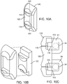
- Each septum 86 has an outer block 120 and an inner block 122, as shown in Fig. 10B , wherein the outer block 120 frames the inner block 122, as shown in Fig. 10A .
- the blocks 120, 122 are composed of a compressible material, such as silicone.
- the demarcation between the blocks 120, 122 forms the slots 118 for receiving the fastening tool.
- the upper edge of the inner block 122 forms an upper slot 118 with the outer block 120
- the lower edge of the inner block 122 forms a lower slot 118 with the outer block 120.
- the upper slot 118 in each septum 86 is adjacent to the aperture 114 in each upper connector block 84
- the lower slot 118 in each septum 86 is adjacent to the aperture 114 in the lower connector block 84.
- a septum only includes one block
- the block is typically pierced with a knife to create the slot for receiving the fastening tool.
- this often results in coring of the material, wherein the cored material hinders insertion of the fastener.
- silicone can demonstrate a tendency to "self-heal," such that a slot formed by piercing a silicone block could close at least partially over time.
- the tendency to self-heal is mitigated, and the slot remains intact.
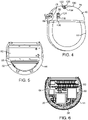
- Each septum 86 is positioned in an opening 124 formed through a surface of the header 46 (see Fig. 4 ), wherein edges of the opening 124 extend over the space underneath to form a frame 126, and the septum 86 is positioned under the frame 126.
- the septum is pushed from outside the header into an opening in the header. However, this often results in the septum becoming loose and being expelled from the header.
- the septum 86 is pushed into the opening 124 from inside the header 46, such that the frame 126 edges extending over the opening 124 prevent the septum 86 from moving outside the opening 124.
- An adhesive such as epoxy, is also applied to adhere the septum 86 to the header 46, such that both mechanical and adhesive elements hold the septum 86 in place. Additional details regarding the connector assemblies and the components associated therewith are found in U.S. Provisional Patent Application No. 61/378,613, filed August 31, 2010 published as US 2012/0053646 A1 ), U.S. Patent No. 7,244,150 , and U.S. Patent Application Serial No. 11/532,844 (published as US 2008-0071320 A1 ).
- the strain relief members 88 in the header 46 extend between each of the retainer ports 90 and the header ports 78.
- the strain relief members 88 are formed as annular seals that help to prevent current leakage outside the header 46 and to hold the lead extensions 24 in position when inserted in the connector assemblies 82 while preventing damage to the lead extensions 24.
- the lower strain relief members 88 have a longer length than the upper strain relief members 88. This is because there is more space between the distal end 102 of the lower connector assembly 82 and retainer port 90 and the corresponding header port 78 than between the upper connector assembly 82 and retainer port 90 and the corresponding header port 78.
- the header 46 also features a suture hole 128 that extends between opposing sides of the header 46.
- a suture needle can go through suture hole 128 by entering one side of the header 46 and exiting on the other side.
- a clinician implanting the IPG 14 may thus use a suture needle with the suture hole 128 to affix the IPG 14 to bodily tissue to help hold the IPG 14 in place.
- Each side of the suture hole 128 is surrounded by a divot 130 in an outer surface of the header 46.
- the divot 130 is cut into the outer surface of the header 46 and has a plurality of side surfaces 132, each side surface 132 preferably angled less than 90 degrees from the outer surface of the header 46, and a bottom surface 134 where the suture hole 128 is positioned.
- the divot 130 and its configuration allow for ease in accessing the header 46 with a suture needle, particularly a curved suture needle, to affix the IPG 14 to bodily tissue.
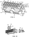
- a feedthrough assembly 136 electrically couples the electronic substrate assembly 50 with the connector assemblies 82.
- the feedthrough assembly 136 includes a plurality of feedthrough pins 138, a metal flange 142 defining a well 144, and one or more ceramic plates 146 positioned in the well 144.
- the feedthrough pins 138 are formed of 10mL wire composed of 90/10 platinum/iridium. In other feedthrough assemblies, the pins are composed of 80/20 platinum/iridium, however, this is less ductile and less compatible with soldering processes during manufacture.
- the number of feedthrough pins 138 corresponds to the number of connector contacts 106 in the connector assemblies 82. In the illustrated embodiment, there are thirty-two feedthrough pins 138.
- the feedthrough pins 138 are coupled to the PCB 54 and extend through the case 44 and header 46 to the connector assemblies 82, where the pins 138 are coupled to the connector contacts 106.
- the feedthrough pins 138 may be coupled to the connector contacts 106 by any suitable method including, for example, welding, soldering, and the like.
- the feedthrough pins 138 are sufficiently long to reach the connector contacts 106 without requiring an additional wire to be soldered to each pin 136. This eliminates the need for additional manufacturing steps, thus limiting production costs and quality issues that would otherwise arise.
- each of the feedthrough pins 138 is inserted in a corresponding hole 148 in the flex circuit 140 (see Fig. 13A ).
- the flex circuit 140 is initially flat, wherein each of the feedthrough pins 138 is inserted through the corresponding hole 148.
- gold braze is applied on the underside of each hole 148 around each pin 138 and seeps through the holes 148 to seal the pins 138 in the holes 148.
- the feedthrough pins 138 are attached to an edge of the flex circuit 140, for example, by laser-soldering or with a conductive epoxy. In another embodiment, a portion of the pins 138 are attached to an edge of the flex circuit 140, and the remaining pins are inserted through holes 148 in the flex circuit 140.
- the feedthrough pins 138 extend through the metal flange 142, which is located at the base of the header 46.
- the metal flange 142 is composed of a biocompatible material, such as titanium.
- the metal flange 142 defines the well 144, which is occupied by the ceramic plates 146.
- the ceramic plates 146 are fused to the metal flange 142 with gold braze.
- two ceramic plates 146 are positioned adjacent each other in the well 144.
- Alternative embodiments may consist of only one ceramic plate 146 that occupies the well 144.
- the ceramic plates 146 have a number of holes 150 corresponding to the number of feedthrough pins 138, such that each pin 138 extends through one corresponding hole 150.
- the pins 138 are fused to the ceramic plates 146 with gold braze that is applied on the underside of the plates 146 and seeps through the holes 150 to cover the pins 138 along the length of the holes 150.
- the ceramic plates 146 have a lower coefficient of expansion than the titanium of the metal flange 142, such that when the components are heated to extremely high temperatures during manufacture, the ceramic plates 146 expand less than the flange 142. As a result, less of the gold braze can seep from between the metal flange 142 and the ceramic plates 146. Also, since the holes 150 receiving the pins 138 in the plates 146 do not widen significantly, the gold braze securing the pins 138 is substantially prevented from seeping through the holes 150, thus serving to stabilize the pins 138.
- each of the feedthrough pins 138 is covered with a silicone tube 152 from the base of the ceramic plates 146 up to the point at which the feedthrough pins 138 couple to the connector contacts 106 (see Fig. 5 ). Additionally, the well 144 is filled with silicone (not shown) to provide further isolation between the pins 138.
Landscapes
- Health & Medical Sciences (AREA)
- Engineering & Computer Science (AREA)
- Biomedical Technology (AREA)
- Nuclear Medicine, Radiotherapy & Molecular Imaging (AREA)
- Radiology & Medical Imaging (AREA)
- Life Sciences & Earth Sciences (AREA)
- Animal Behavior & Ethology (AREA)
- General Health & Medical Sciences (AREA)
- Public Health (AREA)
- Veterinary Medicine (AREA)
- Neurology (AREA)
- Neurosurgery (AREA)
- Electrotherapy Devices (AREA)
Description
- The present invention relates to implantable medical devices, and more particularly, to devices for providing stimulation therapy to patients.
- Implantable stimulation devices generate and deliver electrical stimuli to bodily nerves and tissues for the therapy of various biological disorders, such as: pacemakers to treat cardiac arrhythmia; defibrillators to treat cardiac fibrillation; cochlear stimulators to treat deafness; retinal stimulators to treat blindness; muscle stimulators to produce coordinated limb movement; spinal cord stimulators to treat chronic pain; cortical and deep brain stimulators to treat motor and psychological disorders; and other neural stimulators to treat urinary incontinence, sleep apnea, shoulder sublaxation, etc. The present invention may find applicability in all such applications, although the description that follows will generally focus on the use of the invention within a spinal cord stimulation system, such as that disclosed in
U.S. Pat. No. 6,516,227, issued Feb. 4, 2003 in the name of inventors Paul Meadows et al. - Typical implantable stimulation devices include a neurostimulator, one or more leads electrically coupled to the neurostimulator, and an array of stimulator electrodes on each lead. The stimulator electrodes are in contact with or near the bodily tissue to be stimulated. A pulse generator in the neurostimulator generates electrical pulses that are delivered by the electrodes to bodily tissue. The neurostimulator typically includes an implantable rounded case having circuitry such as a printed circuit board, a telemetry coil for communicating with an external programmer to control the electrical pulses, and a charging coil for charging the neurostimulator.
- The neurostimulator also includes a header having one or more connector assemblies for receiving the leads, wherein the connector assemblies have one or more connector contacts for coupling to the leads. In common models of such neurostimulators, there are two connector assemblies in the header, each having eight contacts. However, to allow for greater range in stimulation parameters, it is desirable for the header to include more electrode contacts for coupling to the lead, for example, thirty-two contacts. At the same time, it is preferred to keep the case and header as small as possible and to maintain a curved configuration for patient comfort. Therefore, a proper neurostimulator design to accommodate thirty-two electrodes, without affecting device performance, is desirable.
- It is also common for neurostimulators to house a telemetry coil in the header. However, this requires a feedthrough to couple the telemetry coil to resonant circuit components and transceiver circuitry in the case. This can add to the complexity of the device and lead to problems with hermeticity. Additionally, the feedthroughs require significant extra steps during manufacture, thus allowing for greater error and quality concerns.
- Another disadvantage of having the telemetry coil in the header is that the coil and the feedthroughs connected to the coil take up space in the header, which may be limited based on the complexity of the stimulation system. At the same time, it is desirable to make stimulation devices smaller for patient comfort. Moreover, while previous neurostimulators had eight or sixteen contacts for coupling to the electrode leads, newer designs may include thirty-two or more contacts, further limiting space in the header.
- Thus, there remains a need for improved stimulation devices that optimize performance with an increased number of electrodes and selective positioning of the telemetry coil, while also having a small, rounded configuration for patient comfort that does not compromise device performance.
-
US 2009/018600 A1 discloses a form for retaining a battery in an implantable medical device that includes an outer edge and first and second opposing major surfaces. The first major surface of the form includes a recess, a ridge disposed between the recess and the outer edge, and a trough forming element disposed between the ridge and the outer edge. The ridge is configured to engage at least a portion of a major surface of the battery retained in the form. The trough forming element has first and second edge surfaces positioned to engage an edge surface of the retained battery to form a trough configured to receive adhesive. The recess is disposed adjacent the ridge and is configured to allow for expansion of the retained battery during recharge. -
WO 2011/059565 A1 , which is not prior art pursuant to Art. 54(2) EPC, discloses an implantable medical device having telemetry and charging coils within a case. - According to the invention, an implantable neurostimulator as recited in the independent claim is provided. The dependent claims define embodiments.
- In accordance with one aspect of the present invention, a tissue stimulation system is provided. The stimulation system has at least one implantable neurostimulation lead and an implantable neurostimulator. The neurostimulator includes at least one connector assembly configured for respectively receiving the at least one neurostimulation lead, a case, a circuit board positioned in the case, a telemetry coil positioned in the case that is electrically coupled to the circuit board and spaced a distance away from the circuit board, and a charging coil positioned in the case that is electrically coupled to the circuit board. The telemetry coil is positioned on a spacer that spaces the telemetry coil the distance away from the circuit board. The telemetry coil and the charging coil are positioned on opposing sides of the circuit board. In an embodiment, a plurality of pins are affixed to the spacer, wherein at least one of the pins electrically couples the telemetry coil to the circuit board, and at least one of the pins mechanically couples the telemetry coil to the circuit board.
- According to the present invention, an implantable neurostimulator is provided. The neurostimulator has a case, a circuit board positioned in the case, a telemetry coil positioned in the case that is electrically coupled to the circuit board and spaced a distance away from the circuit board, and a charging coil positioned in the case that is electrically coupled to the circuit board. The telemetry coil and the charging coil are positioned on opposing sides of the circuit board. The telemetry coil is positioned on a spacer that spaces the telemetry coil the distance away from the circuit board. In an embodiment, a plurality of pins are affixed to the spacer, wherein at least one of the pins electrically couples the telemetry coil to the circuit board, and at least one of the pins mechanically couples the telemetry coil to the circuit board.
- Not part of the invention, there is also disclosed a tissue stimulation system that includes at least one implantable neurostimulation lead and an implantable neurostimulator. The neurostimulator has a header with at least one connector assembly configured for respectively receiving the at least one neurostimulation lead, a circuit board having programming circuitry, and a flex circuit coupled between the at least one connector assembly and the circuit board. In one configuration, the system includes a feedthrough assembly with a plurality of pins coupled to the flex circuit that electrically couple the flex circuit to the at least one connector assembly. In another configuration, one or more of the plurality of pins traverse through one or more holes in the flex circuit. In another configuration, the feedthrough assembly has a metal flange forming a well containing an insulative material, and the pins extend from the flex circuit through the insulative material. In yet another configuration, the at least one connector assembly has a plurality of connector contacts for electrically coupling with the neurostimulation lead, and the pins are electrically coupled to the connector contacts.
- Not part of the invention, there is also disclosed an implantable neurostimulator. The neurostimulator has at least one connector assembly configured for receiving at least one neurostimulation lead, a circuit board having programming circuitry, and a flex circuit coupled between the at least one connector assembly and the circuit board. In one configuration, the system includes a feedthrough assembly with a plurality of pins coupled to the flex circuit that electrically couple the flex circuit to the at least one connector assembly. In another configuration, one or more of the plurality of pins traverse through one or more holes in the flex circuit. In another configuration, the feedthrough assembly has a metal flange forming a well containing an insulative material, and the pins extend from the flex circuit through the insulative material. In yet another configuration, the at least one connector assembly has a plurality of connector contacts for electrically coupling with the neurostimulation lead, and the pins are electrically coupled to the connector contacts.
- Not part of the invention, there is also disclosed a tissue stimulation system that includes at least one implantable neurostimulation lead and an implantable neurostimulator. The neurostimulator has at least one connector assembly configured for respectively receiving the at least one neurostimulation lead, a fastener configured for securing the respective one of the at least one neurostimulation leads in the at least one connector assembly, and at least one septum, each having an outer block and an inner block framed within the outer block. Adjacent edges of the inner and outer blocks form at least one slot for receiving a tool for manipulating the fastener for securing the respective one of the at least one neurostimulation leads in the respective one of the at least one connector assembly. In one configuration, the neurostimulator has a retainer in which the at least one connector assembly is positioned. In another configuration, a connector block is coupled to each at least one connector assembly and has the fastener positioned therein. In another configuration, the outer and inner blocks of the at least one septum are composed of silicone.
- In yet another configuration which does not form part of the invention, the neurostimulator has a shell housing the at least one connector assembly, and the shell has a first transverse line and a second transverse line both aligned parallel to the at least one connector assembly. The first transverse line extends between first opposing ends of the shell, the second transverse line extends between second opposing ends of the shell, and the first transverse line is shorter than the second transverse line. In a further configuration, at least one upper connector assembly longitudinally aligned along the first transverse line, and at least one lower connector assembly longitudinally aligned along the second transverse line. In yet a further configuration, the neurostimulator has at least one upper strain relief member longitudinally aligned along the first transverse line and extending between an end of the at least one upper connector assembly and one of the first opposing ends of the shell, and at least one lower strain relief member longitudinally aligned along the second transverse line and extending between an end of the at least one lower connector assembly and one of the second opposing ends of the shell. The at least one upper strain relief member has a shorter length than the at least one lower strain relief member.
- Not part of the invention, there is also disclosed an implantable neurostimulator. The neurostimulator has at least one connector assembly configured for receiving a neurostimulation lead, a fastener configured for securing the respective one of the at least one neurostimulation leads in the at least one connector assembly, and at least one septum, each having an outer block and an inner block framed within the outer block. Adjacent edges of the inner and outer blocks form at least one slot for receiving a tool for manipulating the fastener for securing the respective one of the at least one neurostimulation leads in the respective one of the at least one connector assembly. In one configuration, the neurostimulator has a retainer in which the at least one connector assembly is positioned. In another configuration, a connector block is coupled to each at least one connector assembly and has the fastener positioned therein. In another configuration, the outer and inner blocks of the at least one septum are composed of silicone.
- In yet another configuration which is not part of the invention, the neurostimulator has a shell housing the at least one connector assembly, and the shell has a first transverse line and a second transverse line both aligned parallel to the at least one connector assembly. The first transverse line extends between first opposing ends of the shell, the second transverse line extends between second opposing ends of the shell, and the first transverse line is shorter than the second transverse line. In a further configuration, at least one upper connector assembly longitudinally aligned along the first transverse line, and at least one lower connector assembly longitudinally aligned along the second transverse line. In yet a further configuration, the neurostimulator has at least one upper strain relief member longitudinally aligned along the first transverse line and extending between an end of the at least one upper connector assembly and one of the first opposing ends of the shell, and at least one lower strain relief member longitudinally aligned along the second transverse line and extending between an end of the at least one lower connector assembly and one of the second opposing ends of the shell. The at least one upper strain relief member has a shorter length than the at least one lower strain relief member.
- Not part of the invention, there is also disclosed an implantable neurostimulator. The neurostimulator has a connector header configured for receiving a neurostimulation lead, a divot formed in each of the opposing sides of the connector header, and a suture hole extending between the divots. In one configuration, each divot has a plurality of side surfaces, and each side surface is angled less than 90 degrees from an outer surface of the connector header. In another configuration, each divot has a bottom surface, and a terminating end of the suture hole is positioned at the bottom surface.
- Not part of the invention, there is also disclosed an implantable neurostimulator. The neurostimulator has a shell having a first transverse line extending between first opposing ends of the shell, and a second transverse line extending between second opposing ends of the shell, wherein the first transverse line is shorter than the second transverse line. The neurostimulator also has at least one upper connector assembly and at least one lower connector assembly housed in the shell, each configured for receiving a neurostimulator lead, wherein the at least one upper connector assembly is longitudinally aligned along the first transverse line, and the at least one lower connector assembly is longitudinally aligned along the second transverse line. The neurostimulator also has at least one upper strain relief member longitudinally aligned along the first transverse line and extending between an end of the at least one upper connector assembly and one of the first opposing ends of the shell, and at least one lower strain relief member longitudinally aligned along the second transverse line and extending between an end of the at least one lower connector assembly and one of the second opposing ends of the shell. The at least one upper strain relief member has a shorter length than the at least one lower strain relief member.
- In one configuration which does not form part of the invention, the at least one upper connector assembly and at least one lower connector assembly has contacts for electrically coupling to the respective electrode lead received therein. In another configuration, the at least one upper connector assembly and at least one lower connector assembly are positioned in a retainer. In yet another configuration, the neurostimulator has at least one upper connector block adjacent the at least one upper connector assembly and at least one lower connector block adjacent the at least one lower connector assembly. In yet another configuration, each of the at least one upper connector block and at least one lower connector block has a fastener disposed therein for securing the respective electrode received in the at least one upper connector assembly and the at least one lower connector assembly.
- Other and further aspects and features of the invention will be evident from reading the following detailed description of the preferred embodiments, which are intended to illustrate, not limit, the invention.
- The drawings illustrate the design and utility of preferred embodiments of the present invention, in which similar elements are referred to by common reference numerals. In order to better appreciate how the above-recited and other advantages and objects of the present inventions are obtained, a more particular description of the present inventions briefly described above will be rendered by reference to specific embodiments thereof, which are illustrated in the accompanying drawings. Understanding that these drawings depict only typical embodiments of the invention and are not therefore to be considered limiting of its scope, the invention will be described and explained with additional specificity and detail through the use of the accompanying drawings in which:
-
Fig. 1 is a plan view of one embodiment of a neurostimulation system arranged in accordance with the present inventions; -
Fig. 2 is a plan view of the neurostimulation system ofFig. 1 in use with a patient; -
Fig. 3 is a side view of a neurostimulator and electrode leads used in the neurostimulation system ofFig. 1 ; -
Fig. 4 is a perspective view of the neurostimulator ofFig. 3 ; -
Figs. 5 and 6 are cut-away views of opposing sides of the neurostimulator ofFig. 3 ; -
Fig. 7 is a side view of a spacer and telemetry coil from the neurostimulator ofFig. 3 ; -
Fig. 8 is a cross-section view of the spacer and telemetry coil ofFig. 7 ; -
Figs. 9 and 10 are partial exploded view of connector assemblies in a retainer element from the neurostimulator ofFig. 3 ; -
Fig. 10A is a perspective view of a septum featured inFig. 9 ; -
Fig. 10B is an exploded view of the septum ofFig. 10A ; -
Fig. 10C is a cross-sectional view of the septum ofFig. 10A taken along theline 10C and connector blocks featured inFig. 9 ; -
Fig. 11 is a perspective view of feedthrough pins coupled to the connector assemblies fromFig. 9 ; -
Fig. 12 is a perspective view of a feedthrough assembly with the feedthrough pins fromFig. 11 ; -
Fig. 13A is a perspective view of a flex circuit having holes for receiving the feedthrough pins fromFigs. 11 and 12 ; and -
Fig. 13B is a cross-sectional view of the flex circuit inFig. 13A taken along theline 13B. - The description that follows relates to a spinal cord stimulation (SCS) system. However, it is to be understood that the while the invention lends itself well to applications in SCS, the invention, in its broadest aspects, may not be so limited. Rather, the invention may be used with any type of implantable electrical circuitry used to stimulate tissue. For example, the present invention may be used as part of a pacemaker, a defibrillator, a cochlear stimulator, a retinal stimulator, a stimulator configured to produce coordinated limb movement, a cortical stimulator, a deep brain stimulator, peripheral nerve stimulator, microstimulator, or in any other neural stimulator configured to treat urinary incontinence, sleep apnea, shoulder sublaxation, headache, etc.
- Turning first to
Fig. 1 , anexemplary SCS system 10 generally includes one or more (in this case, two) implantable neurostimulation leads 12, a neurostimulator (i.e., an implantable pulse generator) (IPG) 14, an externalremote controller RC 16, a clinician's programmer (CP) 18, an External Trial Stimulator (ETS) 20, and anexternal charger 22. - The
IPG 14 is physically connected via one or morepercutaneous lead extensions 24 to the neurostimulation leads 12, which carry a plurality ofelectrodes 26 arranged in an array. In the illustrated embodiment, the neurostimulation leads 12 are percutaneous leads, and to this end, theelectrodes 26 are arranged in-line along the neurostimulation leads 12. In alternative embodiments, theelectrodes 26 may be arranged in a two-dimensional pattern on a single paddle lead. As will be described in further detail below, theIPG 14 includes pulse generation circuitry that delivers electrical stimulation energy in the form of a pulsed electrical waveform (i.e., a temporal series of electrical pulses) to theelectrode array 26 in accordance with a set of stimulation parameters. - The
ETS 20 may also be physically connected via thepercutaneous lead extensions 24 andexternal cable 30 to the neurostimulation leads 12. TheETS 20, which has similar pulse generation circuitry as that of theIPG 14, also delivers electrical stimulation energy in the form of a pulsed electrical waveform to theelectrode array 26 in accordance with a set of stimulation parameters. The major difference between theETS 20 and theIPG 14 is that theETS 20 is a non-implantable device that is used on a trial basis after the neurostimulation leads 12 have been implanted and prior to implantation of theIPG 14, to test the responsiveness of the stimulation that is to be provided. - The
RC 16 may be used to telemetrically control theETS 20 via a bidirectionalinductive link 32. Once theIPG 14 and neurostimulation leads 12 are implanted, theRC 16 may also be used to telemetrically control theIPG 14 via a bidirectionalmagnetic coupling link 34. Such control allows theIPG 14 to be turned on or off and to be programmed with different stimulation parameter sets. TheIPG 14 may also be operated to modify the programmed stimulation parameters to actively control the characteristics of the electrical stimulation energy output by theIPG 14. It should be noted that rather than an IPG, thesystem 10 may alternatively utilize an implantable receiver-stimulator (not shown) connected to thelead 12. In this case, the power source, e.g., a battery, for powering the implanted receiver, as well as control circuitry to command the receiver-stimulator, will be contained in an external controller/charger inductively coupled to the receiver-stimulator via an electromagnetic link. - The
CP 18 provides clinician detailed stimulation parameters for programming theIPG 14 andETS 20 in the operating room and in follow-up sessions. TheCP 18 may perform this function by indirectly communicating with theIPG 14 orETS 20, through theRC 16, via an IR communications link 36. Alternatively, theCP 18 may directly communicate with theIPG 14 orETS 20 via an RF communications link or magnetic coupling link (not shown). The clinician detailed stimulation parameters provided by theCP 18 are also used to program theRC 16, so that the stimulation parameters can be subsequently modified by operation of theRC 16 in a stand-alone mode (i.e., without the assistance of the CP 18). - The
external charger 22 is a portable device used to transcutaneously charge theIPG 14 via aninductive link 38. Once theIPG 14 has been programmed, and its power source has been charged by theexternal charger 22 or otherwise replenished, theIPG 14 may function as programmed without theRC 16 orCP 18 being present. - For purposes of brevity, the details of the
RC 16,CP 18,ETS 20, andexternal charger 22 will not be described herein. Details of exemplary embodiments of these devices are disclosed inU.S. Patent No. 6,895,280 , which is expressly incorporated herein by reference. - As shown in
Fig. 2 , the electrode leads 12 are implanted within thespinal column 42 of apatient 40. The preferred placement of the neurostimulation leads 12 is adjacent, i.e., resting near, or upon the dura, adjacent to the spinal cord area to be stimulated. Due to the lack of space near the location where the electrode leads 12 exit thespinal column 42, theIPG 14 is generally implanted in a surgically-made pocket either in the abdomen or above the buttocks. TheIPG 14 may, of course, also be implanted in other locations of the patient's body. Thelead extension 24 facilitates locating theIPG 14 away from the exit point of the electrode leads 12. As there shown, theCP 18 communicates with theIPG 14 via theRC 16. - Referring now to
Fig. 3 , the external features of the neurostimulation leads 12 and theIPG 14 will be briefly described. In the illustrated embodiment, there are four stimulation leads 12(1)-12(4), wherein neurostimulation lead 12(1) has eight electrodes 26 (labeled E1-E8), neurostimulation lead 12(2) has eight electrodes 26 (labeled E9-E16), neurostimulation lead 12(3) has eight electrodes 26 (labeled E17-E24), and neurostimulation lead 12(4) has eight electrodes 26 (labeled E24-E32). The actual number and shape of leads and electrodes will, of course, vary according to the intended application. - As shown in
Figs. 3 and4 , theIPG 14 comprises anouter case 44 for housing the electronic and other components (described in further detail below), and aheader portion 46 coupled to thecase 44 for receiving the proximal ends of the neurostimulation leads 12(1)-12(4) for mating in a manner that electrically couples theelectrodes 26 to the electronics within thecase 44. - The
outer case 44 is composed of an electrically conductive, biocompatible material, such as titanium 6-4, and forms a hermetically sealed compartment wherein the internal electronics are protected from the body tissue and fluids. In the illustrated embodiment, thecase 44 has a rounded configuration with a maximum circular diameter D of about 50 mm, and preferably about 45 mm, and a maximum thickness W of about 10 mm, and preferably about 8 mm. Thecase 44 is formed using any suitable process, such as casting, molding, and the like. Theheader 46 has a rounded configuration that corresponds with that of thecase 44, such that thecase 44 and theheader 46 together form a rounded body. - As will be described in further detail below, the
IPG 14 includes pulse generation circuitry 48 (seeFig. 6 ) that provides electrical stimulation energy in the form of a pulsed electrical waveform to theelectrode array 26 in accordance with a set of stimulation parameters programmed into theIPG 14. Such stimulation parameters may comprise electrode combinations, which define the electrodes that are activated as anodes (positive), cathodes (negative), and turned off (zero), percentage of stimulation energy assigned to each electrode (fractionalized electrode configurations), and electrical pulse parameters, which define the pulse amplitude (measured in milliamps or volts depending on whether theIPG 14 supplies constant current or constant voltage to the electrode array 26), pulse width (measured in microseconds), pulse rate (measured in pulses per second), and burst rate (measured as the stimulation on duration X and stimulation off duration Y). - Electrical stimulation will occur between two (or more) activated electrodes, one of which may be the
IPG case 44. Stimulation energy may be transmitted to the tissue in a monopolar or multipolar (e.g., bipolar, tripolar, etc.) fashion. Monopolar stimulation occurs when a selected one of thelead electrodes 26 is activated along with thecase 44 of theIPG 14, so that stimulation energy is transmitted between the selectedelectrode 26 andcase 44. Bipolar stimulation occurs when two of thelead electrodes 26 are activated as anode and cathode, so that stimulation energy is transmitted between the selectedelectrodes 26. For example, an electrode on onelead 12 may be activated as an anode at the same time that an electrode on the same lead or anotherlead 12 is activated as a cathode. Tripolar stimulation occurs when three of thelead electrodes 26 are activated, two as anodes and the remaining one as a cathode, or two as cathodes and the remaining one as an anode. For example, two electrodes on onelead 12 may be activated as anodes at the same time that an electrode on anotherlead 12 is activated as a cathode. - The stimulation energy may be delivered between electrodes as monophasic electrical energy or multiphasic electrical energy. Monophasic electrical energy includes a series of pulses that are either all positive (anodic) or all negative (cathodic). Multiphasic electrical energy includes a series of pulses that alternate between positive and negative. For example, multiphasic electrical energy may include a series of biphasic pulses, with each biphasic pulse including a cathodic (negative) stimulation pulse and an anodic (positive) recharge pulse that is generated after the stimulation pulse to prevent direct current charge transfer through the tissue, thereby avoiding electrode degradation and cell trauma. That is, charge is conveyed through the electrode-tissue interface via current at an electrode during a stimulation period (the length of the stimulation pulse), and then pulled back off the electrode-tissue interface via an oppositely polarized current at the same electrode during a recharge period (the length of the recharge pulse).
- Referring to
Figs. 5 and 6 which show opposing internal sides ofcase 44, in performing the above-described stimulation energy generation function, theIPG 14 comprises multiple electronic components, including anelectronic substrate assembly 50 and abattery 52 contained within thecase 44, and a flex circuit 140 (seeFigs. 13A and 13B ) coupled to theelectronic substrate assembly 50. Theflex circuit 140 serves to couple theelectronic substrate assembly 50 to the electronic components in theheader 46, which will be discussed in further detail below. Theelectronic substrate assembly 50 includes a printed circuit board (PCB) 54 to which the previously described pulse generation circuitry 48 is mounted in the form of microprocessors, integrated circuits, capacitors, and other electronic components. Theelectronic substrate assembly 50 further comprises atelemetry coil 56, a chargingcoil 58, and telemetry/chargingcircuitry 60 mounted to thePCB 54. While a portion of the electronic components of theIPG 14 will be described in further detail below, additional details of theIPG 14 and electrical components are disclosed inU.S. Patent No. 6,516,227 . - The
telemetry coil 56 and chargingcoil 58 are positioned on opposing sides of thePCB 54. Significantly, as shown inFigs. 7 and 8 , theelectronic substrate assembly 50 further comprises aspacer 62 on which thetelemetry coil 56 is positioned to space the telemetry coil 56 a distance Dt away from thePCB 54. In the illustrated embodiment, thespacer 62 is abobbin 62. Thebobbin 62 has amain body 64 and anouter flange 66 extending around the periphery of themain body 64 on which thetelemetry coil 56 sits, such that thecoil 56 is wound around themain body 64 in a shape corresponding to that of themain body 64. Here, thetelemetry coil 56 and themain body 64 of thebobbin 62 have a D-shaped configuration for encompassing a wide area in thecase 44 to improve coupling, and hence the reliability of data transfer, between thetelemetry coil 56 and theRC 16. In addition to maintaining the telemetry coil 56 a distance away from thePCB 54, thebobbin 62 is beneficial for manufacture, as thebobbin 62 provides a base on which to shape thetelemetry coil 56, creating a more consistent design than freeform winding of thetelemetry coil 56. - A number of
pins telemetry coil 56 to thePCB 54. In the illustrated embodiment, thebobbin 62 has threeholes 72 extending through themain body 64 of thebobbin 62 for receiving threepins pins 68 electrically connect thetelemetry coil 56 to thePCB 54, and in particular, onepin 68 connects the ground port of thetelemetry coil 56, and the other pin connects the signal port of thetelemetry coil 56. Thethird pin 70 mechanically connects thetelemetry coil 56 to thePCB 54. In the illustrated embodiment, the twoholes 72 for receiving the twoelectrical pins 68 are located on one side of themain body 64 of thebobbin 62, and the onehole 72 for receiving themechanical pin 70 is located on an opposing side of themain body 64 of thebobbin 62. Thepins holes 72 by welding or other suitable means. In this manner, thepins telemetry coil 56 relative to thePCB 54, while the twopins 68 also provide an electrical connection between thetelemetry coil 56 and thePCB 54. In other embodiments, only one pin may be used to electrically connect thetelemetry coil 56 to thePCB 54, or more pins may be used to electrically and/or mechanically connect thetelemetry coil 56 to thePCB 54. - Notably, many typical IPGs contain a charging coil in the case and a telemetry coil in the header. In the illustrated embodiment, however, positioning both the charging
coil 58 and thetelemetry coil 56 in thecase 44 allows more room in theheader 46 for other electronic components. Additionally, positioning thetelemetry coil 56 in thecase 44 eliminates the need for a feedthrough that connects theelectronic substrate assembly 50 with thetelemetry coil 56, as opposed to when a telemetry coil is in the header. - To realize potential effects associated with positioning both the
telemetry coil 56 and chargingcoil 58 in the case, it is helpful to note the operation of thecoils telemetry coil 56, wireless data telemetry between theRC 16 and theIPG 14 occurs via inductive coupling, for example, magnetic inductive coupling. This coupling occurs between thetelemetry coil 56 in theIPG 14 and a corresponding external coil (not shown) in theRC 16. When data is sent from theRC 16 to theIPG 14, the external coil in theRC 16 is energized with an alternating current (AC). This energizing of the external coil to transfer data can occur using a Frequency Shift Keying (FSK) protocol, for example, in which digital data bits in a stream are represented by different frequencies, as disclosed inU.S. Patent Application Serial No. 11/780,369 (publishes asUS 2009/0024179 A1 ). Energizing the external coil with these frequencies produces a magnetic field, which in turn induces a voltage in thetelemetry coil 56 in theIPG 14, producing a corresponding current signal when provided a closed loop path. This voltage and/or current signal can then be demodulated to recover the original data. Transmitting data in the reverse, from thetelemetry coil 56 to the external coil, occurs in essentially the same manner. - Regarding the charging
coil 58, when power is to be transmitted from theexternal charger 22 to theIPG 14, the chargingcoil 58 is energized with an alternating current (AC). Such energizing is generally of a constant frequency and may be of a larger magnitude than that used during data transfer with thetelemetry coil 56, but the basic operation is similar. TheIPG 14 can also communicate back to theexternal charger 22 by modulating the impedance of the chargingcoil 58. This change in impedance is reflected back to theexternal charger 22, which demodulates the reflection to recover the transmitted data. This means of transmitting data from theIPG 14 to theexternal charger 22 is known as Load Shift Keying (LSK) and is useful to communicate data relevant during charging of thebattery 52 in theIPG 14, such as the capacity of thebattery 52, extent of charging completed, and other charging variables. LSK communication between an IPG and external charger is further detailed inU.S. Patent Application Serial No. 12/354,406 . - One possible issue that may arise with positioning both the
telemetry coil 56 and the chargingcoil 58 in thecase 44 is that the mutual inductance of thecoils coil 58 from the chargingcircuitry 60 during periods of telemetry between theIPG 14 and theRC 16. The decoupling circuitry may be activated based on one or more operating factors, for example, when thetelemetry coil 56 is sending or receiving data to/from theRC 16, or when the chargingcircuitry 60 detects no charging alternating current for the chargingcoil 58 to receive. - In another method, the LSK data signal is used to transmit serial data to the
external charger 22 during charging, as is typical, and is also used as a control signal to reduce loading of thetelemetry coil 56 during data telemetry between theIPG 14 and theRC 16. Using the preexisting LSK circuitry in this method requires no change in telemetry circuitry other than to program theIPG 14 circuitry to assert LSK data during periods of data telemetry. Thus, the enhanced circuitry improves reliability of telemetry between theRC 16 and thetelemetry coil 56 without substantial circuitry changes. Additional information regarding the enhanced circuitry is detailed in Application No.12/616,178, filed November 11, 2009 US 2011/0112610 A1 ). - The
bobbin 62 also provides operational benefits with positioning thetelemetry coil 56 and the chargingcoil 58 in thecase 44. For example, thebobbin 62 lessens the interference between thecoils telemetry coil 56 and the chargingcoil 58, as described above. Additionally, thebobbin 62 places thetelemetry coil 56 in closer proximity to thecase 44 to optimize telemetry using resistance from thecase 44. To illustrate, thetelemetry coil 56 may communicate on a seven-band frequency that is achieved by attaining a loss in transmission from resistance, e.g., resistance from adjacent material. In prior embodiments wherein the telemetry coil is positioned in the header, the header provides the resistance needed to obtain the ideal frequency. In the present embodiment, in positioning thetelemetry coil 56 closer to thecase 44, thecase 44 provides the resistance needed to create the desired seven-band frequency fortelemetry coil 56 transmission. - As mentioned above, the
flex circuit 140 serves to couple theelectronic substrate assembly 50 to the electronic components in theheader 46. In particular, theflex circuit 140 is coupled to thePCB 54 and also to feedthrough pins, described in further detail below, that in turn are coupled to leadextensions 24 received in theheader 46. As theflex circuit 140 is a flexible metallic component (see e.g.,Figs. 13A and 13B ), theflex circuit 140 serves as an interface between theelectronic substrate assembly 50 and the electronic components in theheader 46 to provide an electrical coupling function along with the ability to be bent in a suitable configuration to accommodate the size and structure of theIPG 14. - Coupling the
flex circuit 140 to thePCB 54 eliminates the need for soldering an additional plate to thePCB 54, making manufacture more efficient and eliminating related quality issues that may otherwise arise. In some embodiments, theflex circuit 140 may be permanently coupled to thePCB 54, for example, by soldering, laser-welding, applying conductive epoxy or similar adhesive, or crimping. In other embodiments, theflex circuit 140 may be detachably coupled to thePCB 54, for example, by edge connectors such as zero insertion force connectors, snap-fit mechanisms, friction-fit mechanisms, and fasteners such as screws. In one embodiment, the substrate of theflex circuit 140 is composed primarily of polyamide, which may be the same material from which thePCB 54 is primarily composed. Other materials may also be used for the substrate of theflex circuit 140. - As mentioned above, the electronic components within the
case 44 are electrically coupled to theelectrodes 26 vialead extensions 24 received in theheader 46, as shown inFig. 4 . Referring toFigs. 4 and9 , theheader 46 includes: ashell 76 coupled to thecase 44; a plurality ofports 78; aretainer 80; one ormore connector assemblies 82 positioned in theretainer 80; a corresponding number of connector blocks 84 positioned in theretainer 80; one ormore septums 86; and a plurality ofstrain relief members 88. - The
shell 76 is formed using any suitable process, such as casting, molding, and the like, and is composed of a rigid material that does not interfere with the electrical functions of theIPG 14, such as thermoset. The plurality ofports 78 extend through theshell 76 and are configured for receiving thelead extensions 24. Preferably, the number ofports 78 corresponds to the number oflead extensions 24. For example, in the illustrated embodiment, there are fourlead extensions 24 and fourports 78. Theheader ports 78 are also aligned withretainer ports 90, such that thelead extensions 24 are received in theheader ports 78 and then in theretainer 80 through theretainer ports 90. The retainer ports 90 (in this illustrated embodiment, four ports) are in turn aligned with theconnector assemblies 82, such that thelead extensions 24 are received through theretainer ports 90 and then within theconnector assemblies 82. - As shown in
Figs. 9 and 10 , theretainer 80 receives theconnector assemblies 82 in correspondingretainer channels 92 that hold eachrespective connector assembly 82 in position. Theretainer 80 is preferably composed of a rigid material, e.g., thermoplastic, such that theconnector assemblies 82 can be affixed relative to each other. In one embodiment, theconnector assemblies 82 are releasably disposed in theretainer 80 in a suitable manner, such as with an interference fit, snap connection, binders, or other suitable mechanisms.Partitions 94 in theretainer 80 keep theconnector assemblies 82 separated to minimize interference. - The
connector assemblies 82 receive and make electrical contact with thelead extensions 24. Eachconnector assembly 82 has ahousing 96, ahollow center region 98 extending between aproximal end 100 and adistal end 102 of thehousing 96, a plurality ofopenings 104 transversely formed through the wall of thehousing 96, and a plurality ofconnector contacts 106 located within thehollow center region 98. In the illustrated embodiment, there are fourconnector assemblies 82 aligned in a 2x2 configuration to make efficient use of space. Specifically, there are twoupper assemblies 82 and twolower assemblies 82, wherein the twolower assemblies 82 are designated as being closer to thecase 44 than the twoupper assemblies 82. Other embodiments may include oneassembly 82, or twoassemblies 82 or more arranged in a manner suited to the configuration of theIPG 14. Suitable materials for thehousing 96 include, for example, silicone and polyurethane, and multiple materials may be included. Eachlead extension 24 is received through thedistal end 102 of therespective housing 96 into the respectivehollow center region 98. - The
openings 104 in thehousing 96 extend from an outer surface of thehousing 96 to thehollow center region 98. Preferably, thehousing openings 104 are linearly aligned along a side surface of thehousing 96. Eachopening 104 provides access to acorresponding connector contact 106 within thehousing 96. Theconnector contacts 106 are electrically coupled to theelectronic substrate assembly 50 in thecase 44 by a plurality of feedthrough pins, which are explained below in greater detail. - When the
lead extensions 24 are received in theconnector assemblies 82, theconnector contacts 106 electrically couple withterminals 108 disposed on thelead extensions 24. Theterminals 108 are in turn coupled to thelead electrodes 26 with conductive wires (not shown). Preferably, the number and spacing of theconnector contacts 106 in eachconnector assembly 82 correspond to the number and spacing of theterminals 108 on eachlead extension 24 to optimize coupling. In the illustrated embodiment, each of the fourconnector assemblies 82 has eightcontacts 106, and each of the fourlead extensions 24 has eightterminals 108. In this manner, when alead extension 24 is received in thehollow center region 98 of theconnector assembly 82, eachconnector contact 106 electrically couples to acorresponding terminal 108 on thelead extension 24. This results in coupling between theelectronic substrate assembly 50, which is coupled to theconnector contacts 106 by theflex circuit 140 and the feedthrough pins, and theelectrodes 26, which are coupled to theterminals 108. - The
retainer 80 has a number of end stops 110 each located at the proximal ends 100 of thehousings 96 of theconnector assemblies 82. The end stops 110 are typically formed of a compressible material, such as silicone, and may be shaped as a block or alternatively have a curved bowl-shaped configuration. The end stops 110 help to set the pitch for placement of theconnector contacts 106 during manufacture, for example, during precision-based processes such as laser soldering, to prevent irregular placement of theconnector assemblies 82 that would lead to increased expense and quality issues. Also, during operation of theIPG 14, the end stops 110 help limit movement of theconnector assemblies 82 to optimize transmission of electrical pulses from theconnector assemblies 82 to thelead electrodes 26. Additional details regarding setting of pitch and use of end stops for connector assemblies are further described inU.S. Provisional Patent Application No. 61/378,613, filed August 31, 2010 US 2012/0053646 A1 ), andU.S. Patent No. 7,244,150 . - The connector blocks 84 are located at the
distal end 102 of thehousing 96 and may also be coupled to thehousing 96 and/or a wall of theretainer 96. In the illustrated embodiment featuring the 2x2 connector assembly configuration, there are two upper connector blocks 84 adjacent the twoupper assemblies 82 and two lower connector blocks 84 adjacent thelower assemblies 82. Eachconnector block 84 defines aport 112 aligned with thehollow center region 98 for receiving alead extension 24. Eachconnector block 84 also has anaperture 114 on a side of theconnector block 84 through which afastener 116, such as a setscrew or pin, is inserted and secured against thelead extension 24 received therein. This helps to prevent undesirable detachment of thelead extensions 24 from theIPG 14 and to optimize electrical coupling between thelead terminals 108 andconnector contacts 106. - The
septums 86 have one ormore slots 118 aligned with theconnector block apertures 114 for receiving a fastening tool to secure thefastener 116 in eachaperture 114. Theseptums 86 are positioned adjacent to, and may also be coupled to, the connector blocks 84. In the illustrated embodiment, twoseptums 86 are positioned on opposing sides of theheader 46, wherein eachseptum 86 is adjacent to two connector blocks 84. Eachseptum 86 has anouter block 120 and aninner block 122, as shown inFig. 10B , wherein theouter block 120 frames theinner block 122, as shown inFig. 10A . Theblocks blocks slots 118 for receiving the fastening tool. For example, the upper edge of theinner block 122 forms anupper slot 118 with theouter block 120, and the lower edge of theinner block 122 forms alower slot 118 with theouter block 120. Additionally, as shown inFig. 10C , theupper slot 118 in eachseptum 86 is adjacent to theaperture 114 in eachupper connector block 84, and thelower slot 118 in eachseptum 86 is adjacent to theaperture 114 in thelower connector block 84. - Notably, in other devices wherein a septum only includes one block, the block is typically pierced with a knife to create the slot for receiving the fastening tool. However, this often results in coring of the material, wherein the cored material hinders insertion of the fastener. Additionally, silicone can demonstrate a tendency to "self-heal," such that a slot formed by piercing a silicone block could close at least partially over time. However, by implementing two silicone blocks that are pushed together, as in the illustrated embodiment, the tendency to self-heal is mitigated, and the slot remains intact.
- Each
septum 86 is positioned in anopening 124 formed through a surface of the header 46 (seeFig. 4 ), wherein edges of theopening 124 extend over the space underneath to form aframe 126, and theseptum 86 is positioned under theframe 126. In typical manufacturing practices, the septum is pushed from outside the header into an opening in the header. However, this often results in the septum becoming loose and being expelled from the header. In the present embodiment, however, theseptum 86 is pushed into the opening 124 from inside theheader 46, such that theframe 126 edges extending over theopening 124 prevent theseptum 86 from moving outside theopening 124. An adhesive, such as epoxy, is also applied to adhere theseptum 86 to theheader 46, such that both mechanical and adhesive elements hold theseptum 86 in place. Additional details regarding the connector assemblies and the components associated therewith are found inU.S. Provisional Patent Application No. 61/378,613, filed August 31, 2010 US 2012/0053646 A1 ),U.S. Patent No. 7,244,150 , andU.S. Patent Application Serial No. 11/532,844 (published asUS 2008-0071320 A1 ). - The
strain relief members 88 in theheader 46 extend between each of theretainer ports 90 and theheader ports 78. In the illustrated embodiment, there are fourstrain relief members 88 that correspond with the 2x2 configuration of theconnector assemblies 82, such that there are two upper and two lowerstrain relief members 88. Thestrain relief members 88 are formed as annular seals that help to prevent current leakage outside theheader 46 and to hold thelead extensions 24 in position when inserted in theconnector assemblies 82 while preventing damage to thelead extensions 24. To correspond with the curved formation of theheader 46, the lowerstrain relief members 88 have a longer length than the upperstrain relief members 88. This is because there is more space between thedistal end 102 of thelower connector assembly 82 andretainer port 90 and thecorresponding header port 78 than between theupper connector assembly 82 andretainer port 90 and thecorresponding header port 78. - In the illustrated embodiment, the
header 46 also features asuture hole 128 that extends between opposing sides of theheader 46. To illustrate, a suture needle can go throughsuture hole 128 by entering one side of theheader 46 and exiting on the other side. A clinician implanting theIPG 14 may thus use a suture needle with thesuture hole 128 to affix theIPG 14 to bodily tissue to help hold theIPG 14 in place. Each side of thesuture hole 128 is surrounded by adivot 130 in an outer surface of theheader 46. Thedivot 130 is cut into the outer surface of theheader 46 and has a plurality of side surfaces 132, eachside surface 132 preferably angled less than 90 degrees from the outer surface of theheader 46, and abottom surface 134 where thesuture hole 128 is positioned. Thedivot 130 and its configuration allow for ease in accessing theheader 46 with a suture needle, particularly a curved suture needle, to affix theIPG 14 to bodily tissue. - Referring to
Figs. 11-13B , afeedthrough assembly 136 electrically couples theelectronic substrate assembly 50 with theconnector assemblies 82. Thefeedthrough assembly 136 includes a plurality of feedthrough pins 138, ametal flange 142 defining a well 144, and one or moreceramic plates 146 positioned in thewell 144. - The feedthrough pins 138 are formed of 10mL wire composed of 90/10 platinum/iridium. In other feedthrough assemblies, the pins are composed of 80/20 platinum/iridium, however, this is less ductile and less compatible with soldering processes during manufacture. Preferably, the number of feedthrough pins 138 corresponds to the number of
connector contacts 106 in theconnector assemblies 82. In the illustrated embodiment, there are thirty-two feedthrough pins 138. The feedthrough pins 138 are coupled to thePCB 54 and extend through thecase 44 andheader 46 to theconnector assemblies 82, where thepins 138 are coupled to theconnector contacts 106. The feedthrough pins 138 may be coupled to theconnector contacts 106 by any suitable method including, for example, welding, soldering, and the like. Notably, the feedthrough pins 138 are sufficiently long to reach theconnector contacts 106 without requiring an additional wire to be soldered to eachpin 136. This eliminates the need for additional manufacturing steps, thus limiting production costs and quality issues that would otherwise arise. - As mentioned above, the feedthrough pins 138 are each coupled to the
flex circuit 140, which may be achieved in various manners. In the illustrated embodiment, each of the feedthrough pins 138 is inserted in acorresponding hole 148 in the flex circuit 140 (seeFig. 13A ). To insert the feedthrough pins 138 through theflex circuit 140 during manufacture, theflex circuit 140 is initially flat, wherein each of the feedthrough pins 138 is inserted through thecorresponding hole 148. Using laser soldering, gold braze is applied on the underside of eachhole 148 around eachpin 138 and seeps through theholes 148 to seal thepins 138 in theholes 148. This provides a metallurgical adhesive and electrical connection, which may be advantageous over other sealants that only serve as an adhesive. Conductive epoxy may also be used to seal thepins 138 in theholes 148. Theflex circuit 140 is then bent into a curved configuration to suitably fit in theIPG 14 and to orient thepins 138 upward for insertion through theheader 46. - In another embodiment, the feedthrough pins 138 are attached to an edge of the
flex circuit 140, for example, by laser-soldering or with a conductive epoxy. In another embodiment, a portion of thepins 138 are attached to an edge of theflex circuit 140, and the remaining pins are inserted throughholes 148 in theflex circuit 140. - In entering the
header 46, the feedthrough pins 138 extend through themetal flange 142, which is located at the base of theheader 46. Themetal flange 142 is composed of a biocompatible material, such as titanium. As mentioned above, themetal flange 142 defines the well 144, which is occupied by theceramic plates 146. Theceramic plates 146 are fused to themetal flange 142 with gold braze. In the illustrated embodiment, twoceramic plates 146 are positioned adjacent each other in thewell 144. Alternative embodiments may consist of only oneceramic plate 146 that occupies thewell 144. Theceramic plates 146 have a number ofholes 150 corresponding to the number of feedthrough pins 138, such that eachpin 138 extends through one correspondinghole 150. Thepins 138 are fused to theceramic plates 146 with gold braze that is applied on the underside of theplates 146 and seeps through theholes 150 to cover thepins 138 along the length of theholes 150. - The
ceramic plates 146 have a lower coefficient of expansion than the titanium of themetal flange 142, such that when the components are heated to extremely high temperatures during manufacture, theceramic plates 146 expand less than theflange 142. As a result, less of the gold braze can seep from between themetal flange 142 and theceramic plates 146. Also, since theholes 150 receiving thepins 138 in theplates 146 do not widen significantly, the gold braze securing thepins 138 is substantially prevented from seeping through theholes 150, thus serving to stabilize thepins 138. - To isolate the feedthrough pins 138 from each other and limit electrical connectivity in between, and to further provide protection to the
pins 138 in the transition between thecase 44 and theheader 46, each of the feedthrough pins 138 is covered with asilicone tube 152 from the base of theceramic plates 146 up to the point at which the feedthrough pins 138 couple to the connector contacts 106 (seeFig. 5 ). Additionally, the well 144 is filled with silicone (not shown) to provide further isolation between thepins 138. - Although particular embodiments of the present inventions have been shown and described, it will be understood that it is not intended to limit the present inventions to the preferred embodiments, and it will be obvious to those skilled in the art that various changes and modifications may be made without departing from the scope of the invention which is defined by the claims.
Claims (12)
- An implantable neurostimulator (14), comprising:a case (44);a circuit board (54) positioned in the case (44);a telemetry coil (56) positioned in the case (44) that is electrically coupled to the circuit board (54) and spaced a distance away from the circuit board (54);a charging coil (58) positioned in the case (44) that is electrically coupled to the circuit board (54), wherein the telemetry coil (56) and the charging coil (58) are positioned on opposing sides of the circuit board; anda spacer (62) on which the telemetry coil (56) is positioned for spacing the telemetry coil (56) the distance away from the circuit board (54).
- The neurostimulator of claim 1, further comprising a plurality of pins (68, 70) affixed to the spacer (62), wherein at least one of the pins (68) electrically couples the telemetry coil (56) to the circuit board (54), and at least one of the pins (70) mechanically couples the telemetry coil (56) to the circuit board (54).
- The neurostimulator of claim 1, further comprising decoupling circuitry that selectively alters operation of the charging coil (58).
- The neurostimulator of claim 3, wherein the decoupling circuitry selectively alters operation of the charging coil (58) based on one or more operating factors of at least one of the charging coil (58) and the telemetry coil (56).
- The neurostimulator of claim 1, wherein the spacer (62) comprises a bobbin (62).
- The neurostimulator of claim 1, further comprising at least one connector assembly (82) configured for receiving at least one neurostimulation lead (12).
- The neurostimulator of claim 6, wherein the at least one connector assembly (82) comprises two or more connector assemblies (82).
- The neurostimulator of claim 7, wherein the two or more connector assemblies (82) comprise four connector assemblies (82).
- A tissue stimulation system (10), comprising:at least one implantable neurostimulation lead (12); andan implantable neurostimulator (14) according to any of claims 6 to 8, wherein, the at least one connector assembly (82) is configured for respectively receiving the at least one neurostimulation lead (12).
- The tissue stimulation system of claim 9, wherein the neurostimulator (14) further comprises a plurality of pins (68, 70) affixed to the spacer (62), wherein at least one of the pins (68) electrically couples the telemetry coil (56) to the circuit board (54), and at least one of the pins (70) mechanically couples the telemetry coil (56) to the circuit board (54).
- The tissue stimulation system of claim 9, further comprising decoupling circuitry that selectively alters operation of the charging coil (58).
- The tissue stimulation system of claim 11, wherein the decoupling circuitry selectively alters operation of the charging coil (58) based on one or more operating factors of at least one of the charging coil (58) and the telemetry coil (56).
Priority Applications (2)
| Application Number | Priority Date | Filing Date | Title |
|---|---|---|---|
| EP23157722.2A EP4218917A1 (en) | 2011-02-24 | 2012-02-23 | Implantable neurostimulator with a circuit board and a connector |
| EP22168815.3A EP4062968A1 (en) | 2011-02-24 | 2012-02-23 | Implantable neurostimulator with a circuit board and a connector |
Applications Claiming Priority (2)
| Application Number | Priority Date | Filing Date | Title |
|---|---|---|---|
| US201161446438P | 2011-02-24 | 2011-02-24 | |
| PCT/US2012/026370 WO2012116214A1 (en) | 2011-02-24 | 2012-02-23 | Implantable neurostimulator with a circuit board and a connector |
Related Child Applications (3)
| Application Number | Title | Priority Date | Filing Date |
|---|---|---|---|
| EP22168815.3A Division EP4062968A1 (en) | 2011-02-24 | 2012-02-23 | Implantable neurostimulator with a circuit board and a connector |
| EP22168815.3A Division-Into EP4062968A1 (en) | 2011-02-24 | 2012-02-23 | Implantable neurostimulator with a circuit board and a connector |
| EP23157722.2A Division EP4218917A1 (en) | 2011-02-24 | 2012-02-23 | Implantable neurostimulator with a circuit board and a connector |
Publications (2)
| Publication Number | Publication Date |
|---|---|
| EP2678072A1 EP2678072A1 (en) | 2014-01-01 |
| EP2678072B1 true EP2678072B1 (en) | 2022-06-15 |
Family
ID=45787392
Family Applications (3)
| Application Number | Title | Priority Date | Filing Date |
|---|---|---|---|
| EP23157722.2A Pending EP4218917A1 (en) | 2011-02-24 | 2012-02-23 | Implantable neurostimulator with a circuit board and a connector |
| EP12707023.3A Active EP2678072B1 (en) | 2011-02-24 | 2012-02-23 | Implantable neurostimulator with a circuit board and a connector |
| EP22168815.3A Withdrawn EP4062968A1 (en) | 2011-02-24 | 2012-02-23 | Implantable neurostimulator with a circuit board and a connector |
Family Applications Before (1)
| Application Number | Title | Priority Date | Filing Date |
|---|---|---|---|
| EP23157722.2A Pending EP4218917A1 (en) | 2011-02-24 | 2012-02-23 | Implantable neurostimulator with a circuit board and a connector |
Family Applications After (1)
| Application Number | Title | Priority Date | Filing Date |
|---|---|---|---|
| EP22168815.3A Withdrawn EP4062968A1 (en) | 2011-02-24 | 2012-02-23 | Implantable neurostimulator with a circuit board and a connector |
Country Status (6)
| Country | Link |
|---|---|
| US (5) | US8738138B2 (en) |
| EP (3) | EP4218917A1 (en) |
| JP (1) | JP2014508600A (en) |
| AU (1) | AU2012220569B2 (en) |
| CA (1) | CA2828234A1 (en) |
| WO (1) | WO2012116214A1 (en) |
Families Citing this family (42)
| Publication number | Priority date | Publication date | Assignee | Title |
|---|---|---|---|---|
| US9084901B2 (en) | 2006-04-28 | 2015-07-21 | Medtronic, Inc. | Cranial implant |
| EP2313148B1 (en) | 2008-07-30 | 2013-08-21 | Ecole Polytechnique Fédérale de Lausanne | Apparatus for optimized stimulation of a neurological target |
| AU2009315316B2 (en) | 2008-11-12 | 2015-11-05 | Ecole Polytechnique Federale De Lausanne | Microfabricated neurostimulation device |
| JP5927176B2 (en) | 2010-04-01 | 2016-06-01 | エコーレ ポリテクニーク フェデラーレ デ ローザンヌ (イーピーエフエル) | Device for interacting with neural tissue and methods of making and using it |
| WO2013111137A2 (en) | 2012-01-26 | 2013-08-01 | Rainbow Medical Ltd. | Wireless neurqstimulatqrs |
| EP2888002B1 (en) | 2012-08-23 | 2018-02-21 | Boston Scientific Neuromodulation Corporation | Implantable electrical stimulation systems with shielding |
| US9861812B2 (en) | 2012-12-06 | 2018-01-09 | Blue Wind Medical Ltd. | Delivery of implantable neurostimulators |
| US20150018911A1 (en) | 2013-07-02 | 2015-01-15 | Greatbatch Ltd. | Apparatus, system, and method for minimized energy in peripheral field stimulation |
| WO2015034833A1 (en) * | 2013-09-06 | 2015-03-12 | Boston Scientific Neuromodulation Corporation | Systems and methods for reducing electromagnetic field-induced heating from an implantable pulse generator |
| WO2015173787A1 (en) | 2014-05-16 | 2015-11-19 | Aleva Neurotherapeutics Sa | Device for interacting with neurological tissue and methods of making and using the same |
| US11311718B2 (en) | 2014-05-16 | 2022-04-26 | Aleva Neurotherapeutics Sa | Device for interacting with neurological tissue and methods of making and using the same |
| US9782581B2 (en) | 2014-06-27 | 2017-10-10 | Boston Scientific Neuromodulation Corporation | Methods and systems for electrical stimulation including a shielded sheath |
| CA2958197C (en) | 2014-08-15 | 2023-09-26 | Axonics Modulation Technologies, Inc. | External pulse generator device and associated methods for trial nerve stimulation |
| EP3180069B1 (en) | 2014-08-17 | 2020-05-13 | Nine Continents Medical, Inc. | Miniature implatable neurostimulator system for sciatic nerves and their branches |
| US9474894B2 (en) | 2014-08-27 | 2016-10-25 | Aleva Neurotherapeutics | Deep brain stimulation lead |
| JP2017538519A (en) | 2014-12-17 | 2017-12-28 | ハートウェア、インコーポレイテッド | Implantable connector |
| WO2016160423A1 (en) | 2015-03-27 | 2016-10-06 | Boston Scientific Neuromodulation Corporation | Systems and methods for making and using electrical stimulation systems to reduce rf-induced tissue heating |
| US10238879B2 (en) * | 2015-04-06 | 2019-03-26 | Cardiac Pacemakers, Inc. | Implantable medical devices with flexible interconnect having strain relief |
| WO2016176645A1 (en) | 2015-04-30 | 2016-11-03 | Boston Scientific Neuromodulation Corporation | Electrical stimulation leads and systems having a rf shield along at least the lead and methods of making and using |
| KR101656723B1 (en) * | 2015-06-30 | 2016-09-12 | 재단법인 오송첨단의료산업진흥재단 | Feedthrough making method |
| US10105540B2 (en) | 2015-11-09 | 2018-10-23 | Bluewind Medical Ltd. | Optimization of application of current |
| US10576292B2 (en) * | 2015-11-29 | 2020-03-03 | Boston Scientific Neuromodulation Corporation | Skull-mounted deep brain stimulator |
| US10420950B2 (en) | 2015-11-29 | 2019-09-24 | Boston Scientific Neuromodulation Corporation | Implantable pulse generator usable during a trial stimulation phase and externally powered by magnetic inductive coupling |
| EP3411111A1 (en) | 2016-02-02 | 2018-12-12 | Aleva Neurotherapeutics SA | Treatment of autoimmune diseases with deep brain stimulation |
| WO2017139784A1 (en) | 2016-02-12 | 2017-08-17 | Axonics Modulation Technologies, Inc. | External pulse generator device and associated methods for trial nerve stimulation |
| WO2018017463A1 (en) | 2016-07-18 | 2018-01-25 | Nalu Medical, Inc. | Methods and systems for treating pelvic disorders and pain conditions |
| US10543374B2 (en) * | 2016-09-30 | 2020-01-28 | Boston Scientific Neuromodulation Corporation | Connector assemblies with bending limiters for electrical stimulation systems and methods of making and using same |
| US10124178B2 (en) | 2016-11-23 | 2018-11-13 | Bluewind Medical Ltd. | Implant and delivery tool therefor |
| EP3585475B1 (en) | 2017-02-24 | 2024-04-03 | Nalu Medical, Inc. | Apparatus with sequentially implanted stimulators |
| US10758734B2 (en) * | 2017-02-28 | 2020-09-01 | Boston Scientific Neuromodulation Corporation | Implantable medical device with a silicone housing |
| US20180272138A1 (en) | 2017-03-21 | 2018-09-27 | Boston Scientific Neuromodulation Corporation | Microstimulator with Rigid Support Structure |
| US20180272134A1 (en) | 2017-03-21 | 2018-09-27 | Boston Scientific Neuromodulation Corporation | Microstimulator Having Body-Mounted Electrodes and Remote Electrode Leads |
| EP3384958A1 (en) * | 2017-04-03 | 2018-10-10 | BIOTRONIK SE & Co. KG | Feedthrough for implant components |
| US20180353764A1 (en) | 2017-06-13 | 2018-12-13 | Bluewind Medical Ltd. | Antenna configuration |
| US10702692B2 (en) | 2018-03-02 | 2020-07-07 | Aleva Neurotherapeutics | Neurostimulation device |
| US11331501B2 (en) | 2018-06-22 | 2022-05-17 | Greatbatch Ltd. | Implantable pulse generator with multiple suture ports |
| CN109472914A (en) * | 2018-11-20 | 2019-03-15 | 河北家和康孕信息技术有限公司 | A kind of self-supporting medical terminal and method |
| WO2020242900A1 (en) | 2019-05-24 | 2020-12-03 | Axonics Modulation Technologies, Inc. | Trainer device for a neurostimulator programmer and associated methods of use with a neurostimulation system |
| CN110840457B (en) * | 2019-12-12 | 2020-11-13 | 北京航空航天大学 | Two-dimensional EIT electrode array structure optimization method based on fringe field detection |
| CN113856047B (en) * | 2021-08-23 | 2023-05-26 | 西湖大学 | Hypoglossal nerve stimulation device |
| CN113694373A (en) * | 2021-09-01 | 2021-11-26 | 苏州景昱医疗器械有限公司 | Nerve electrical stimulation equipment and connecting module and connecting device thereof |
| US11400299B1 (en) | 2021-09-14 | 2022-08-02 | Rainbow Medical Ltd. | Flexible antenna for stimulator |
Citations (1)
| Publication number | Priority date | Publication date | Assignee | Title |
|---|---|---|---|---|
| WO2011059565A1 (en) * | 2009-11-11 | 2011-05-19 | Boston Scientific Neuromodulation Corporation | Structure for an implantable medical device having telemetry and charging coils within a case |
Family Cites Families (26)
| Publication number | Priority date | Publication date | Assignee | Title |
|---|---|---|---|---|
| US4276882A (en) * | 1979-05-18 | 1981-07-07 | Medtronic, Inc. | Lead anchoring device |
| JPH05144494A (en) * | 1991-11-18 | 1993-06-11 | Matsushita Refrig Co Ltd | Hermetically sealed terminal and hermetic motor-driven compressor |
| WO2000064535A1 (en) * | 1999-04-26 | 2000-11-02 | Advanced Neuromodulation Systems, Inc. | Lead connector |
| US6516227B1 (en) | 1999-07-27 | 2003-02-04 | Advanced Bionics Corporation | Rechargeable spinal cord stimulator system |
| JP2002263201A (en) * | 2001-03-08 | 2002-09-17 | Terumo Corp | Implantable medical device |
| US8195295B2 (en) * | 2008-03-20 | 2012-06-05 | Greatbatch Ltd. | Shielded three-terminal flat-through EMI/energy dissipating filter |
| US6721602B2 (en) * | 2001-08-21 | 2004-04-13 | Medtronic, Inc. | Implantable medical device assembly and manufacturing method |
| JP4193975B2 (en) * | 2002-10-24 | 2008-12-10 | 株式会社生方製作所 | Airtight terminal unit |
| US7719854B2 (en) * | 2003-07-31 | 2010-05-18 | Cardiac Pacemakers, Inc. | Integrated electromagnetic interference filters and feedthroughs |
| US20050131483A1 (en) | 2003-12-11 | 2005-06-16 | Jennifer Zhao | Connector header setscrew for an implantable medical device |
| US20050203584A1 (en) | 2004-03-10 | 2005-09-15 | Medtronic, Inc. | Telemetry antenna for an implantable medical device |
| US7083474B1 (en) * | 2004-12-08 | 2006-08-01 | Pacesetter, Inc. | System for lead retention and sealing of an implantable medical device |
| US7337003B2 (en) * | 2005-01-25 | 2008-02-26 | Advanced Bionics Corporation | Implantable pulse generator case |
| US7775215B2 (en) * | 2005-02-24 | 2010-08-17 | Ethicon Endo-Surgery, Inc. | System and method for determining implanted device positioning and obtaining pressure data |
| US7244150B1 (en) | 2006-01-09 | 2007-07-17 | Advanced Bionics Corporation | Connector and methods of fabrication |
| JP2008053007A (en) * | 2006-08-23 | 2008-03-06 | Sony Corp | Multicore current introduction terminal and cable |
| US8224450B2 (en) * | 2006-09-18 | 2012-07-17 | Boston Scientific Neuromodulation Corporation | Feed through interconnect assembly for an implantable stimulation system and methods of making and using |
| US8082037B2 (en) | 2007-07-12 | 2011-12-20 | Medtronic, Inc. | Form for retaining battery in implantable medical device |
| US8233986B2 (en) * | 2007-07-12 | 2012-07-31 | Medtronic, Inc. | Connector header for implantable medical device |
| US9162068B2 (en) | 2007-07-16 | 2015-10-20 | Boston Scientific Neuromodulation Corporation | Energy efficient resonant driving circuit for magnetically coupled telemetry |
| US7736191B1 (en) * | 2008-05-27 | 2010-06-15 | Jerzy Roman Sochor | Implantable connector with protected contacts |
| US7941227B2 (en) * | 2008-09-03 | 2011-05-10 | Boston Scientific Neuromodulation Corporation | Implantable electric stimulation system and methods of making and using |
| EP2337610B1 (en) * | 2008-09-25 | 2017-07-19 | Koninklijke Philips N.V. | Apparatus with wireless communication module |
| US9370664B2 (en) | 2009-01-15 | 2016-06-21 | Boston Scientific Neuromodulation Corporation | Signaling error conditions in an implantable medical device system using simple charging coil telemetry |
| EP2611499A1 (en) | 2010-08-31 | 2013-07-10 | Boston Scientific Neuromodulation Corporation | Control module with a connector assembly retainer |
| US8989872B2 (en) * | 2012-11-14 | 2015-03-24 | Medtronic, Inc. | Implantable medical device header |
-
2012
- 2012-02-23 EP EP23157722.2A patent/EP4218917A1/en active Pending
- 2012-02-23 CA CA2828234A patent/CA2828234A1/en not_active Abandoned
- 2012-02-23 JP JP2013555570A patent/JP2014508600A/en active Pending
- 2012-02-23 EP EP12707023.3A patent/EP2678072B1/en active Active
- 2012-02-23 US US13/403,779 patent/US8738138B2/en not_active Expired - Fee Related
- 2012-02-23 WO PCT/US2012/026370 patent/WO2012116214A1/en active Application Filing
- 2012-02-23 AU AU2012220569A patent/AU2012220569B2/en active Active
- 2012-02-23 EP EP22168815.3A patent/EP4062968A1/en not_active Withdrawn
-
2014
- 2014-04-11 US US14/251,488 patent/US8989864B2/en active Active
-
2015
- 2015-03-19 US US14/663,222 patent/US9597519B2/en active Active
-
2017
- 2017-02-24 US US15/442,324 patent/US9907966B2/en not_active Expired - Fee Related
-
2018
- 2018-01-17 US US15/873,705 patent/US10279188B2/en active Active
Patent Citations (1)
| Publication number | Priority date | Publication date | Assignee | Title |
|---|---|---|---|---|
| WO2011059565A1 (en) * | 2009-11-11 | 2011-05-19 | Boston Scientific Neuromodulation Corporation | Structure for an implantable medical device having telemetry and charging coils within a case |
Also Published As
| Publication number | Publication date |
|---|---|
| AU2012220569B2 (en) | 2016-04-28 |
| EP4062968A1 (en) | 2022-09-28 |
| CA2828234A1 (en) | 2012-08-30 |
| US20140222111A1 (en) | 2014-08-07 |
| AU2012220569A1 (en) | 2013-09-05 |
| US20120221074A1 (en) | 2012-08-30 |
| US20170157406A1 (en) | 2017-06-08 |
| JP2014508600A (en) | 2014-04-10 |
| US8989864B2 (en) | 2015-03-24 |
| US9907966B2 (en) | 2018-03-06 |
| US9597519B2 (en) | 2017-03-21 |
| US20180154160A1 (en) | 2018-06-07 |
| US20150190645A1 (en) | 2015-07-09 |
| US8738138B2 (en) | 2014-05-27 |
| EP4218917A1 (en) | 2023-08-02 |
| WO2012116214A1 (en) | 2012-08-30 |
| US10279188B2 (en) | 2019-05-07 |
| EP2678072A1 (en) | 2014-01-01 |
Similar Documents
| Publication | Publication Date | Title |
|---|---|---|
| US10279188B2 (en) | Implantable medical device for providing stimulation therapy | |
| EP2121126B1 (en) | Filtering capacitor feedthrough assembly | |
| EP2497527B1 (en) | Low insertion force electrical connector for implantable medical devices | |
| US10420950B2 (en) | Implantable pulse generator usable during a trial stimulation phase and externally powered by magnetic inductive coupling | |
| US20180272134A1 (en) | Microstimulator Having Body-Mounted Electrodes and Remote Electrode Leads | |
| Peckham et al. | Implantable neural stimulators | |
| US10016593B2 (en) | Implantable medical device having electromagnetic interference filter device to reduce pocket tissue heating | |
| US10857366B2 (en) | Holder for an implantable medical device | |
| US20180272138A1 (en) | Microstimulator with Rigid Support Structure | |
| US20230372720A1 (en) | Header Assembly For Connecting An Active Medical Device To A Lead | |
| US20200306540A1 (en) | Systems and methods for making and using a low-profile control module for an electrical stimulation system | |
| EP3187224B1 (en) | Electrical connector ring for implantable medical device |
Legal Events
| Date | Code | Title | Description |
|---|---|---|---|
| PUAI | Public reference made under article 153(3) epc to a published international application that has entered the european phase |
Free format text: ORIGINAL CODE: 0009012 |
|
| 17P | Request for examination filed |
Effective date: 20130920 |
|
| AK | Designated contracting states |
Kind code of ref document: A1 Designated state(s): AL AT BE BG CH CY CZ DE DK EE ES FI FR GB GR HR HU IE IS IT LI LT LU LV MC MK MT NL NO PL PT RO RS SE SI SK SM TR |
|
| DAX | Request for extension of the european patent (deleted) | ||
| STAA | Information on the status of an ep patent application or granted ep patent |
Free format text: STATUS: EXAMINATION IS IN PROGRESS |
|
| 17Q | First examination report despatched |
Effective date: 20190503 |
|
| STAA | Information on the status of an ep patent application or granted ep patent |
Free format text: STATUS: EXAMINATION IS IN PROGRESS |
|
| STAA | Information on the status of an ep patent application or granted ep patent |
Free format text: STATUS: EXAMINATION IS IN PROGRESS |
|
| GRAP | Despatch of communication of intention to grant a patent |
Free format text: ORIGINAL CODE: EPIDOSNIGR1 |
|
| STAA | Information on the status of an ep patent application or granted ep patent |
Free format text: STATUS: GRANT OF PATENT IS INTENDED |
|
| INTG | Intention to grant announced |
Effective date: 20220110 |
|
| GRAS | Grant fee paid |
Free format text: ORIGINAL CODE: EPIDOSNIGR3 |
|
| GRAA | (expected) grant |
Free format text: ORIGINAL CODE: 0009210 |
|
| STAA | Information on the status of an ep patent application or granted ep patent |
Free format text: STATUS: THE PATENT HAS BEEN GRANTED |
|
| AK | Designated contracting states |
Kind code of ref document: B1 Designated state(s): AL AT BE BG CH CY CZ DE DK EE ES FI FR GB GR HR HU IE IS IT LI LT LU LV MC MK MT NL NO PL PT RO RS SE SI SK SM TR |
|
| REG | Reference to a national code |
Ref country code: CH Ref legal event code: EP Ref country code: GB Ref legal event code: FG4D |
|
| REG | Reference to a national code |
Ref country code: IE Ref legal event code: FG4D |
|
| REG | Reference to a national code |
Ref country code: DE Ref legal event code: R096 Ref document number: 602012078359 Country of ref document: DE |
|
| REG | Reference to a national code |
Ref country code: AT Ref legal event code: REF Ref document number: 1497992 Country of ref document: AT Kind code of ref document: T Effective date: 20220715 |
|
| REG | Reference to a national code |
Ref country code: NL Ref legal event code: FP |
|
| REG | Reference to a national code |
Ref country code: LT Ref legal event code: MG9D |
|
| PG25 | Lapsed in a contracting state [announced via postgrant information from national office to epo] |
Ref country code: SE Free format text: LAPSE BECAUSE OF FAILURE TO SUBMIT A TRANSLATION OF THE DESCRIPTION OR TO PAY THE FEE WITHIN THE PRESCRIBED TIME-LIMIT Effective date: 20220615 Ref country code: NO Free format text: LAPSE BECAUSE OF FAILURE TO SUBMIT A TRANSLATION OF THE DESCRIPTION OR TO PAY THE FEE WITHIN THE PRESCRIBED TIME-LIMIT Effective date: 20220915 Ref country code: LT Free format text: LAPSE BECAUSE OF FAILURE TO SUBMIT A TRANSLATION OF THE DESCRIPTION OR TO PAY THE FEE WITHIN THE PRESCRIBED TIME-LIMIT Effective date: 20220615 Ref country code: HR Free format text: LAPSE BECAUSE OF FAILURE TO SUBMIT A TRANSLATION OF THE DESCRIPTION OR TO PAY THE FEE WITHIN THE PRESCRIBED TIME-LIMIT Effective date: 20220615 Ref country code: GR Free format text: LAPSE BECAUSE OF FAILURE TO SUBMIT A TRANSLATION OF THE DESCRIPTION OR TO PAY THE FEE WITHIN THE PRESCRIBED TIME-LIMIT Effective date: 20220916 Ref country code: FI Free format text: LAPSE BECAUSE OF FAILURE TO SUBMIT A TRANSLATION OF THE DESCRIPTION OR TO PAY THE FEE WITHIN THE PRESCRIBED TIME-LIMIT Effective date: 20220615 Ref country code: BG Free format text: LAPSE BECAUSE OF FAILURE TO SUBMIT A TRANSLATION OF THE DESCRIPTION OR TO PAY THE FEE WITHIN THE PRESCRIBED TIME-LIMIT Effective date: 20220915 |
|
| REG | Reference to a national code |
Ref country code: AT Ref legal event code: MK05 Ref document number: 1497992 Country of ref document: AT Kind code of ref document: T Effective date: 20220615 |
|
| PG25 | Lapsed in a contracting state [announced via postgrant information from national office to epo] |
Ref country code: RS Free format text: LAPSE BECAUSE OF FAILURE TO SUBMIT A TRANSLATION OF THE DESCRIPTION OR TO PAY THE FEE WITHIN THE PRESCRIBED TIME-LIMIT Effective date: 20220615 Ref country code: LV Free format text: LAPSE BECAUSE OF FAILURE TO SUBMIT A TRANSLATION OF THE DESCRIPTION OR TO PAY THE FEE WITHIN THE PRESCRIBED TIME-LIMIT Effective date: 20220615 |
|
| PG25 | Lapsed in a contracting state [announced via postgrant information from national office to epo] |
Ref country code: SM Free format text: LAPSE BECAUSE OF FAILURE TO SUBMIT A TRANSLATION OF THE DESCRIPTION OR TO PAY THE FEE WITHIN THE PRESCRIBED TIME-LIMIT Effective date: 20220615 Ref country code: SK Free format text: LAPSE BECAUSE OF FAILURE TO SUBMIT A TRANSLATION OF THE DESCRIPTION OR TO PAY THE FEE WITHIN THE PRESCRIBED TIME-LIMIT Effective date: 20220615 Ref country code: RO Free format text: LAPSE BECAUSE OF FAILURE TO SUBMIT A TRANSLATION OF THE DESCRIPTION OR TO PAY THE FEE WITHIN THE PRESCRIBED TIME-LIMIT Effective date: 20220615 Ref country code: PT Free format text: LAPSE BECAUSE OF FAILURE TO SUBMIT A TRANSLATION OF THE DESCRIPTION OR TO PAY THE FEE WITHIN THE PRESCRIBED TIME-LIMIT Effective date: 20221017 Ref country code: ES Free format text: LAPSE BECAUSE OF FAILURE TO SUBMIT A TRANSLATION OF THE DESCRIPTION OR TO PAY THE FEE WITHIN THE PRESCRIBED TIME-LIMIT Effective date: 20220615 Ref country code: EE Free format text: LAPSE BECAUSE OF FAILURE TO SUBMIT A TRANSLATION OF THE DESCRIPTION OR TO PAY THE FEE WITHIN THE PRESCRIBED TIME-LIMIT Effective date: 20220615 Ref country code: CZ Free format text: LAPSE BECAUSE OF FAILURE TO SUBMIT A TRANSLATION OF THE DESCRIPTION OR TO PAY THE FEE WITHIN THE PRESCRIBED TIME-LIMIT Effective date: 20220615 Ref country code: AT Free format text: LAPSE BECAUSE OF FAILURE TO SUBMIT A TRANSLATION OF THE DESCRIPTION OR TO PAY THE FEE WITHIN THE PRESCRIBED TIME-LIMIT Effective date: 20220615 |
|
| PG25 | Lapsed in a contracting state [announced via postgrant information from national office to epo] |
Ref country code: PL Free format text: LAPSE BECAUSE OF FAILURE TO SUBMIT A TRANSLATION OF THE DESCRIPTION OR TO PAY THE FEE WITHIN THE PRESCRIBED TIME-LIMIT Effective date: 20220615 Ref country code: IS Free format text: LAPSE BECAUSE OF FAILURE TO SUBMIT A TRANSLATION OF THE DESCRIPTION OR TO PAY THE FEE WITHIN THE PRESCRIBED TIME-LIMIT Effective date: 20221015 |
|
| REG | Reference to a national code |
Ref country code: DE Ref legal event code: R097 Ref document number: 602012078359 Country of ref document: DE |
|
| PG25 | Lapsed in a contracting state [announced via postgrant information from national office to epo] |
Ref country code: AL Free format text: LAPSE BECAUSE OF FAILURE TO SUBMIT A TRANSLATION OF THE DESCRIPTION OR TO PAY THE FEE WITHIN THE PRESCRIBED TIME-LIMIT Effective date: 20220615 |
|
| PLBE | No opposition filed within time limit |
Free format text: ORIGINAL CODE: 0009261 |
|
| STAA | Information on the status of an ep patent application or granted ep patent |
Free format text: STATUS: NO OPPOSITION FILED WITHIN TIME LIMIT |
|
| PG25 | Lapsed in a contracting state [announced via postgrant information from national office to epo] |
Ref country code: DK Free format text: LAPSE BECAUSE OF FAILURE TO SUBMIT A TRANSLATION OF THE DESCRIPTION OR TO PAY THE FEE WITHIN THE PRESCRIBED TIME-LIMIT Effective date: 20220615 |
|
| 26N | No opposition filed |
Effective date: 20230316 |
|
| PG25 | Lapsed in a contracting state [announced via postgrant information from national office to epo] |
Ref country code: SI Free format text: LAPSE BECAUSE OF FAILURE TO SUBMIT A TRANSLATION OF THE DESCRIPTION OR TO PAY THE FEE WITHIN THE PRESCRIBED TIME-LIMIT Effective date: 20220615 |
|
| PG25 | Lapsed in a contracting state [announced via postgrant information from national office to epo] |
Ref country code: MC Free format text: LAPSE BECAUSE OF FAILURE TO SUBMIT A TRANSLATION OF THE DESCRIPTION OR TO PAY THE FEE WITHIN THE PRESCRIBED TIME-LIMIT Effective date: 20220615 |
|
| REG | Reference to a national code |
Ref country code: CH Ref legal event code: PL |
|
| REG | Reference to a national code |
Ref country code: BE Ref legal event code: MM Effective date: 20230228 |
|
| PG25 | Lapsed in a contracting state [announced via postgrant information from national office to epo] |
Ref country code: LU Free format text: LAPSE BECAUSE OF NON-PAYMENT OF DUE FEES Effective date: 20230223 Ref country code: LI Free format text: LAPSE BECAUSE OF NON-PAYMENT OF DUE FEES Effective date: 20230228 Ref country code: CH Free format text: LAPSE BECAUSE OF NON-PAYMENT OF DUE FEES Effective date: 20230228 |
|
| PG25 | Lapsed in a contracting state [announced via postgrant information from national office to epo] |
Ref country code: IT Free format text: LAPSE BECAUSE OF FAILURE TO SUBMIT A TRANSLATION OF THE DESCRIPTION OR TO PAY THE FEE WITHIN THE PRESCRIBED TIME-LIMIT Effective date: 20220615 |
|
| PG25 | Lapsed in a contracting state [announced via postgrant information from national office to epo] |
Ref country code: BE Free format text: LAPSE BECAUSE OF NON-PAYMENT OF DUE FEES Effective date: 20230228 |
|
| PGFP | Annual fee paid to national office [announced via postgrant information from national office to epo] |
Ref country code: NL Payment date: 20240123 Year of fee payment: 13 |
|
| PGFP | Annual fee paid to national office [announced via postgrant information from national office to epo] |
Ref country code: IE Payment date: 20240125 Year of fee payment: 13 |
|
| PGFP | Annual fee paid to national office [announced via postgrant information from national office to epo] |
Ref country code: DE Payment date: 20240123 Year of fee payment: 13 Ref country code: GB Payment date: 20240123 Year of fee payment: 13 |
|
| PGFP | Annual fee paid to national office [announced via postgrant information from national office to epo] |
Ref country code: FR Payment date: 20240123 Year of fee payment: 13 |