EP2888002B1 - Implantable electrical stimulation systems with shielding - Google Patents
Implantable electrical stimulation systems with shielding Download PDFInfo
- Publication number
- EP2888002B1 EP2888002B1 EP13756773.1A EP13756773A EP2888002B1 EP 2888002 B1 EP2888002 B1 EP 2888002B1 EP 13756773 A EP13756773 A EP 13756773A EP 2888002 B1 EP2888002 B1 EP 2888002B1
- Authority
- EP
- European Patent Office
- Prior art keywords
- lead
- control module
- connector assembly
- disposed
- conductive
- Prior art date
- Legal status (The legal status is an assumption and is not a legal conclusion. Google has not performed a legal analysis and makes no representation as to the accuracy of the status listed.)
- Not-in-force
Links
Images


Classifications
-
- A—HUMAN NECESSITIES
- A61—MEDICAL OR VETERINARY SCIENCE; HYGIENE
- A61N—ELECTROTHERAPY; MAGNETOTHERAPY; RADIATION THERAPY; ULTRASOUND THERAPY
- A61N1/00—Electrotherapy; Circuits therefor
- A61N1/18—Applying electric currents by contact electrodes
- A61N1/32—Applying electric currents by contact electrodes alternating or intermittent currents
- A61N1/36—Applying electric currents by contact electrodes alternating or intermittent currents for stimulation
- A61N1/372—Arrangements in connection with the implantation of stimulators
- A61N1/375—Constructional arrangements, e.g. casings
- A61N1/3752—Details of casing-lead connections
-
- A—HUMAN NECESSITIES
- A61—MEDICAL OR VETERINARY SCIENCE; HYGIENE
- A61N—ELECTROTHERAPY; MAGNETOTHERAPY; RADIATION THERAPY; ULTRASOUND THERAPY
- A61N1/00—Electrotherapy; Circuits therefor
- A61N1/02—Details
- A61N1/04—Electrodes
- A61N1/05—Electrodes for implantation or insertion into the body, e.g. heart electrode
-
- A—HUMAN NECESSITIES
- A61—MEDICAL OR VETERINARY SCIENCE; HYGIENE
- A61N—ELECTROTHERAPY; MAGNETOTHERAPY; RADIATION THERAPY; ULTRASOUND THERAPY
- A61N1/00—Electrotherapy; Circuits therefor
- A61N1/16—Screening or neutralising undesirable influences from or using, atmospheric or terrestrial radiation or fields
-
- A—HUMAN NECESSITIES
- A61—MEDICAL OR VETERINARY SCIENCE; HYGIENE
- A61N—ELECTROTHERAPY; MAGNETOTHERAPY; RADIATION THERAPY; ULTRASOUND THERAPY
- A61N1/00—Electrotherapy; Circuits therefor
- A61N1/18—Applying electric currents by contact electrodes
- A61N1/32—Applying electric currents by contact electrodes alternating or intermittent currents
- A61N1/36—Applying electric currents by contact electrodes alternating or intermittent currents for stimulation
- A61N1/3605—Implantable neurostimulators for stimulating central or peripheral nerve system
- A61N1/36128—Control systems
- A61N1/36142—Control systems for improving safety
-
- A—HUMAN NECESSITIES
- A61—MEDICAL OR VETERINARY SCIENCE; HYGIENE
- A61N—ELECTROTHERAPY; MAGNETOTHERAPY; RADIATION THERAPY; ULTRASOUND THERAPY
- A61N1/00—Electrotherapy; Circuits therefor
- A61N1/02—Details
- A61N1/08—Arrangements or circuits for monitoring, protecting, controlling or indicating
- A61N1/086—Magnetic resonance imaging [MRI] compatible leads
Definitions
- the present invention is directed to implantable electrical stimulation leads having a shield on the header of a control module, or to a lead extension having a shield on the connector assembly.
- Implantable electrical stimulation systems have proven therapeutic in a variety of diseases and disorders.
- spinal cord stimulation systems have been used as a therapeutic modality for the treatment of chronic pain syndromes.
- Peripheral nerve stimulation has been used to treat incontinence, as well as a number of other applications under investigation.
- Functional electrical stimulation systems have been applied to restore some functionality to paralyzed extremities in spinal cord injury patients.
- a stimulator can include a control module (with a pulse generator), one or more leads, and an array of stimulator electrodes on each lead.
- the stimulator electrodes are in contact with or near the nerves, muscles, or other tissue to be stimulated.
- the pulse generator in the control module generates electrical pulses that are delivered by the electrodes to body tissue.
- MRI magnetic resonance imaging
- RF radio frequency
- An implantable control module with a conductive shield over at least a portion of the header is known from US2008/0039898 A1 .
- a tube-shaped shielding element disposed within the connector assembly of a medical lead extension is disclosed in US2012/0130461 A1 .
- the present invention is directed to the area of implantable electrical stimulation systems. Also disclosed are methods of making and using the systems. There is also disclosed an implantable electrical stimulation leads having a shield on or within the header of a control module, as well as methods of making and using the leads and electrical stimulation systems.
- Suitable implantable electrical stimulation systems include, but are not limited to, an electrode lead ("lead”) with one or more electrodes disposed on a distal end of the lead and one or more terminals disposed on one or more proximal ends of the lead.
- Leads include, for example, percutaneous leads, paddle leads, and cuff leads. Examples of electrical stimulation systems with leads are found in, for example, U.S. Patents Nos.
- FIG. 1 illustrates schematically one embodiment of an electrical stimulation system 100.
- the electrical stimulation system includes a control module (e.g., a stimulator or pulse generator) 102, a paddle body 104, and one or more lead bodies 106 coupling the control module 102 to the paddle body 104.
- the paddle body 104 and the one or more lead bodies 106 form a lead.
- the paddle body 104 typically includes an array of electrodes 134.
- the control module 102 typically includes an electronic subassembly 110 and an optional power source 120 disposed in a sealed body 114.
- two lead bodies 106 are shown coupled to the control module 102.
- the control module 102 typically includes one or more connector assemblies 144 into which the proximal end of the one or more lead bodies 106 can be plugged to make an electrical connection via connector contacts (e.g., 316 in Figures 3A-3B ; and 340 of Figure 3C ) disposed in the connector assembly 144 and terminals (e.g., 310 in Figures 3A-3C ) on each of the one or more lead bodies 106.
- the connector contacts are coupled to the electronic subassembly 110 and the terminals are coupled to the electrodes 134.
- two connector assemblies 144 are shown.
- the one or more connector assemblies 144 may be disposed in a header 150.
- the header 150 provides a protective covering over the one or more connector assemblies 144.
- the header 150 may be formed using any suitable process including, for example, casting, molding (including injection molding), and the like.
- one or more lead extensions 324 can be disposed between the one or more lead bodies 106 and the control module 102 to extend the distance between the one or more lead bodies 106 and the control module 102.
- the electrical stimulation system can include more, fewer, or different components and can have a variety of different configurations including those configurations disclosed in the electrical stimulation system references cited herein.
- the electrodes 134 can be disposed in an array at or near the distal end of the lead body 106 forming a percutaneous lead, as illustrated in Figure 2 .
- a percutaneous lead may be isodiametric along the length of the lead body 106.
- the electrical stimulation system or components of the electrical stimulation system including one or more of the lead bodies 106, the control module 102, and, in the case of a paddle lead, the paddle body 104, are typically implanted into the body of a patient.
- the electrical stimulation system can be used for a variety of applications including, but not limited to, spinal cord stimulation, brain stimulation, neural stimulation, muscle stimulation, cardiac stimulation, and the like.
- the electrodes 134 can be formed using any conductive, biocompatible material. Examples of suitable materials include metals, alloys, conductive polymers, conductive carbon, and the like, as well as combinations thereof. In at least some embodiments, one or more of the electrodes 134 are formed from one or more of: platinum, platinum iridium, palladium, titanium, or rhenium.
- the number of electrodes 134 in the array of electrodes 134 may vary. For example, there can be two, three, four, five, six, seven, eight, nine, ten, eleven, twelve, thirteen, fourteen, fifteen, sixteen, or more electrodes 134. As will be recognized, other numbers of electrodes 134 may also be used. As will be recognized, other numbers of electrodes 134 may also be used. In Figure 1 , sixteen electrodes 134 are shown.
- the electrodes 134 can be formed in any suitable shape including, for example, round, oval, triangular, rectangular, pentagonal, hexagonal, heptagonal, octagonal, or the like.
- the electrodes of the paddle body 104 or one or more lead bodies 106 are typically disposed in, or separated by, a non-conductive, biocompatible material including, for example, silicone, polyurethane, and the like or combinations thereof.
- the paddle body 104 and one or more lead bodies 106 may be formed in the desired shape by any process including, for example, molding (including injection molding), casting, and the like. Electrodes and connecting wires can be disposed onto or within a paddle body either prior to or subsequent to a molding or casting process.
- the non-conductive material typically extends from the distal end of the lead to the proximal end of each of the one or more lead bodies 106.
- the non-conductive, biocompatible material of the paddle body 104 and the one or more lead bodies 106 may be the same or different.
- the paddle body 104 and the one or more lead bodies 106 may be a unitary structure or can be formed as two separate structures that are permanently or detachably coupled together.
- Terminals are typically disposed at the proximal end of the one or more lead bodies 106 for connection to corresponding conductive contacts (e.g., 316 in Figures 3A-3B ; and 340 of Figure 3C ) in connector assemblies ( e.g., 144 in Figures 1-3C ) disposed on, for example, the control module 102 (or to other devices, such as conductive contacts on a lead extension, an operating room cable, a splitter, an adaptor, or the like).
- Conductive wires extend from the terminals (e.g., 310 in Figures 3A-3C ) to the electrodes 134.
- one or more electrodes 134 are electrically coupled to a terminal ( e.g., 310 in Figures 3A-3C ).
- each terminal e.g., 310 in Figures 3A-3C
- the conductive wires may be embedded in the non-conductive material of the lead or can be disposed in one or more lumens (not shown) extending along the lead. In some embodiments, there is an individual lumen for each conductive wire. In other embodiments, two or more conductive wires may extend through a lumen. There may also be one or more lumens (not shown) that open at, or near, the proximal end of the lead, for example, for inserting a stylet rod to facilitate placement of the lead within a body of a patient. Additionally, there may also be one or more lumens (not shown) that open at, or near, the distal end of the lead, for example, for infusion of drugs or medication into the site of implantation of the paddle body 104.
- the one or more lumens may be flushed continually, or on a regular basis, with saline, epidural fluid, or the like. In at least some embodiments, the one or more lumens can be permanently or removably sealable at the distal end.
- the one or more lead bodies 106 may be coupled to the one or more connector assemblies 144 disposed on the control module 102.
- the control module 102 can include any suitable number of connector assemblies 144 including, for example, two three, four, five, six, seven, eight, or more connector assemblies 144. It will be understood that other numbers of connector assemblies 144 may be used instead.
- each of the two lead bodies 106 includes eight terminals that are shown coupled with eight conductive contacts disposed in a different one of two different connector assemblies 144.
- leads are coupled to connectors disposed on control modules.
- Figure 3A is a schematic perspective view of one embodiment of a single connector assembly 144 disposed on the control module 102.
- Figure 3B is a schematic perspective view of one embodiment of a plurality of connector assemblies 144 disposed on the control module 102.
- the control module 102 includes two connector assemblies 144.
- the control module 102 includes four connector assemblies 144.
- the proximal ends 306 of one or more lead bodies 106 are shown configured and arranged for insertion to the control module 102.
- the one or more connector assemblies 144 are disposed in the header 150.
- the header 150 defines one or more ports 304 into which a proximal end 306 of the one or more lead bodies 106 with terminals 310 can be inserted, as shown by directional arrows 312, in order to gain access to the connector contacts disposed in the one or more connector assemblies 144.
- the one or more connector assemblies 144 each include a connector housing 314 and a plurality of connector contacts 316 disposed therein.
- the connector housing 314 defines a port (not shown) that provides access to the plurality of connector contacts 316.
- one or more of the connector assemblies 144 further includes a retaining element 318 configured and arranged to fasten the corresponding lead body 308 to the connector assembly 144 when the lead body 106 is inserted into the connector assembly 144 to prevent undesired detachment of the lead body 106 from the connector assembly 144.
- the retaining element 318 may include an aperture through which a fastener (e.g., a set screw, pin, or the like) may be inserted and secured against an inserted lead body or lead extension.
- the connector contacts 316 can be aligned with the terminals 310 disposed on the one or more lead bodies 106 to electrically couple the control module 102 to the electrodes (134 of Figure 1 ) disposed at a distal end of the one or more lead bodies 106.
- Examples of connector assemblies in control modules are found in, for example, U.S. Patent No. 7,244,150 and 8,224,450 , which are incorporated by reference.
- a lead extension connector assembly 322 is disposed on a lead extension 324.
- the lead extension connector assembly 322 is shown disposed at a distal end 326 of the lead extension 324.
- the lead extension connector assembly 322 includes a contact housing 328.
- the contact housing 328 defines at least one port 330 into which a proximal end 306 of the lead body 106 with terminals 310 can be inserted, as shown by directional arrow 338.
- the lead extension connector assembly 322 also includes a plurality of connector contacts 340.
- the connector contacts 340 disposed in the contact housing 328 can be aligned with the terminals 310 on the lead body 106 to electrically couple the lead extension 324 to the electrodes (134 of Figure 1 ) disposed at a distal end (not shown) of the lead body 106.
- the proximal end of a lead extension can be similarly configured and arranged as a proximal end of a lead body.
- the lead extension 324 may include a plurality of conductive wires (not shown) that electrically couple the connector contacts 340 to a proximal end 348 of the lead extension 324 that is opposite to the distal end 326.
- the conductive wires disposed in the lead extension 324 can be electrically coupled to a plurality of terminals (not shown) disposed on the proximal end 348 of the lead extension 324.
- the proximal end 348 of the lead extension 324 is configured and arranged for insertion into a lead extension connector assembly disposed in another lead extension.
- the proximal end 348 of the lead extension 324 is configured and arranged for insertion into the connector assembly 144 disposed on the control module 102.
- Conventional electrical stimulation systems may be potentially unsate for use with magnetic resonance imaging ("MRI") due to the effects of electromagnetic fields (e.g ., radio frequency fields and magnetic field gradients) in an MRI environment.
- a common mechanism for causing the electrical interactions between the electrical stimulation system and radiofrequency (“RF") irradiation is common-mode coupling of the applied electromagnetic fields that act as a series of distributed sources along elongated conductive structures, such as leads, or conductors within leads.
- Common-mode induced RF currents can reach amplitudes of greater than one ampere in MRI environments. Such currents can cause heating and potentially disruptive voltages within electronic circuits, such as electronic circuits disposed within the electronic subassembly.
- Some of the effects of RF irradiation may include, for example, inducing current in the lead, causing undesired heating around the lead that may potentially cause tissue damage, undesired or unexpected operation of electronic components, or damage to, or premature failure of, electronic components. Additionally, when an electrical stimulation system is used within an MRI scanner environment, the electrical interactions between the electrical stimulation system and the MRI may cause distortions in images formed by the MRI system.
- RF energy When the lead is exposed to electromagnetic fields, RF energy may be induced along the length of the lead. It has been found that in many instances a major portion of the RF energy induced in the lead occurs in the distal and proximal ends of the lead.
- the lead When the lead is coupled to the control module, at least some of the RF energy induced along the lead may propagate from the lead to the control module.
- the RF energy may, for example, propagate between the terminals of the lead and the connector contacts of the connector assembly of the control module. Once the induced RF energy reaches the control module, the RF energy may propagate along a plurality of different conductive paths to the electronic subassembly.
- tissue near the junction between the header 150 and sealed body 114 of the control module 102 may occur in tissue near the junction between the header 150 and sealed body 114 of the control module 102 (see, Figure 2 ), particularly when the exterior of the sealed body is made of metal (e.g., titanium) or metalized and the header 150 is made of a non-conductive material (e.g ., medical grade epoxy or polyurethane). It is believed that the discontinuity in the dielectric constant and conductivity between the tissue and the header may cause electromagnetic fields and currents to build up especially near the header-tissue-sealed body interface and cause local heating (e.g ., "hotspots") in the adjacent tissue.
- metal e.g., titanium
- a non-conductive material e.g ., medical grade epoxy or polyurethane
- Shielding of at least a portion of the header of the control module can reduce the current induced in attached leads and delivered to the control module. It is also believed that the shielding may reduce or eliminate the dielectric discontinuity between the header and the tissue resulting in lower or more homogenous tissue heating.
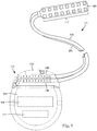
- Figure 4 illustrates one arrangement with a metal shield 470 disposed over at least a portion of the header 450 of the control module 402.
- the shield 470 does not extend over the ports 304 ( FIG. 3A ) that receive the leads (or lead extensions).
- the shield 470 can be made of any suitable biocompatible material such as metals or alloys, including, but not limited to, copper, stainless steel, titanium, and the like.
- the shield 470 may take the form of, for example, a solid sheet or foil of material, a mesh, or a layer of conductive material formed (for example, by physical or chemical deposition) on the control module or on a substrate (for example, a polymeric substrate) disposed on the header, or any combination thereof.
- the shield 470 may be removable from the control module 402. In at least some embodiments, the shield 470 may be permanently or temporarily affixed to the control module 402. Affixation can be accomplished using, for example, adhesive, soldering, welding, brazing, press fitting, or any other suitable affixation method or medium.
- the shield 470 may be attached to the control module 402 as part of the manufacture of the control module. In some embodiments, the shield may be attached or otherwise coupled to the control module after manufacture of the control module. In some embodiments, a shield may be arranged to retrofit an existing control module or as an optional component for the control module.
- the shield 470 (or any of the other shields described herein) may be coupled to the electronic subassembly 110 ( Figure 1 ) of the control module 402 (for example, coupled to interconnects that extend between the header and the sealed body) so that the shield 470 can act as a return electrode in combination with one or more of the electrodes on the lead.
- the sealed body 114 ( Figure 1 ) of the control module may be non-conductive.
- the shield may include a window to allow a practitioner to view a portion of the lead(s) inserted into the header to verify insertion or alignment of the lead(s) within the control module using visual or imaging (e.g. , x-ray imaging) techniques.
- Figure 5A illustrates one embodiment of a shield 570 with at least one window 575 and disposed on a header 550 of a control module 502. The proximal ends of the leads 506 are visible through the window 575, as are the conductive contacts 516 of the header 550.
- a window 575 may be provided on only one side of the shield 570 or on both opposing sides of the shield.
- the window 575 may have any suitable regular or irregular shape including, but not limited to, square, rectangular, circular, oval, triangular, and the like. In this embodiment, the perimeter of the window 575 is defined on all sides by the shield 570.
- Figure 5B illustrates another embodiment of a shield 570 with at least one window 575 and disposed on a header 550 of a control module 502.
- the window 575 can be a cutout portion of the shield 570 where less than the entire perimeter of the window 575 is surrounded by the shield 570.
- the window 575 is not necessarily cut out of the shield, but that the shield may be initially formed with the window.
- the term "window” is used to indicate that the shield 570 does not cover the entire header, but rather leaves a portion of the header uncovered so that the practitioner can observe a portion of the lead(s) through the window.
- a shield may include more than one window. It will also be recognized that a window in the shield may be provided for some purpose other than observation of the lead(s) inserted into the header of the control module. It will also be recognized that one or more windows may be incorporated in any of the other embodiments of a shield discussed below.
- a shield 670 is formed on, or disposed over, the header 650 of a control module 602.
- the shield 670 includes a surface that is structured as a frequency selective surface.
- Frequency selective surfaces, and methods of making such surfaces, are known.
- At least some embodiments of a frequency selective surface include two-dimensional periodic arrays of metallic elements with specific geometric shapes or arrangements (or both) formed on a substrate (such as a polymeric substrate or the surface of the header 650).
- the frequency selective surface is a two-dimensional array of apertures in a metallic sheet or foil with the apertures having specific geometric shapes or arrangements (or both).
- the period and shape (or other parameters, such as thickness) of the metallic elements or apertures can be selected and tuned to a particular frequency or to two or more frequencies or to one or more bands of frequencies.
- a shield 670 may have a frequency selective surface that is tuned to one or more expected RF frequencies used in MRI procedures such as, for example, 64 MHz or 128 MHz (or both) to attenuate transmission of the electromagnetic energy at the tuned frequency or frequencies into the header. Electromagnetic energy at other frequencies will be less attenuated by the shield or not attenuated at all.
- Such a shield 670 may be desirable as, at least in some embodiments, it allows low frequency signals, such as telemetry signals which may be used to operate, reprogram, or otherwise communicate with the control module, to be received by the control module while at least partially shielding from RF frequencies used in MRI procedures.
- low frequency signals such as telemetry signals which may be used to operate, reprogram, or otherwise communicate with the control module, to be received by the control module while at least partially shielding from RF frequencies used in MRI procedures.
- the frequency selective surface may be formed directly on the header of the control module, for example, as a patterned layer formed on the control module using deposition and photolithographic or other patterning techniques. In at least some embodiments, the frequency selective surface may be formed on a substrate, such as a polymer substrate, which is then placed over at least a portion of the header of the control module.
- a shield may include a series of slats, stripes or other thin structures to shield electromagnetic fields that are not parallel to these structures.
- Figure 7 illustrates one embodiment of a shield 770 disposed on a header 750 of a control module 702.
- the shield 770 includes multiple elongated conductive structures 772, such as slats or stripes. In at least some embodiments, these elongate conductive structures 772 are arranged to extend parallel one or more lead(s) inserted in the control module 702. The width, thickness, material, or other parameters of the elongated structures may be uniform or non-uniform.
- the width, thickness, material, or other parameters of the elongated structures, or any combination thereof, may be selected to facilitate shielding of electromagnetic radiation having a particular orientation or polarization (e.g., polarized perpendicular to the elongated structures) or orientations or a particular frequency or frequencies. It will be understood that, in at least some embodiments, the shield 770 may preferentially reflect or absorb one polarization of electromagnetic radiation and preferentially transmit another polarization of the electromagnetic radiation.
- the elongated structures 772 may be formed directly on the header 750 of the control module 770, for example, as a patterned layer formed on the control module using deposition and photolithographic or other patterning techniques. In at least some embodiments, the elongated structures 772 may be formed on a substrate, such as a polymer substrate, which is then placed over at least a portion of the header of the control module.
- the plastic material of the header includes a doping or impregnating conductive material that renders that plastic material conductive and able to shield RF energy.
- Figure 8 illustrates one embodiment of a header 850 of a control module 802 where the header includes a plastic material that is doped or impregnated with a conductive material to render the plastic material conductive to shield from RF energy.
- suitable conductive material for doping or impregnating the plastic material include, but are not limited to, metal or alloy particles or conductive carbon particles or conductive polymers.
- the plastic material can be any suitable plastic material such as, for example, silicone, polyurethane, or polyetheretherketone.
- the doped or impregnated plastic material preferably extends through at least the portion of the header surrounding the conductive assembly or conductive assemblies 144 ( Figure 1 ) into which the lead(s) are to be inserted.
- the doped or impregnated plastic material does not conductively couple to any of the contacts within the conductive assembly otherwise it may short the contacts and affect stimulation signal delivery.
- a shield disposed on or in the header may be electrically coupled to a conductive structure, such as an electrode, disposed, or otherwise formed, on the surface of the body of the control module.
- this conductive structure is an electrode that is coupled to the electronic subassembly 110 ( Figure 1 ) disposed within the body of the control module. This electrode may, for example, act as a return electrode in conjunction with one or more electrodes on the leads 106 ( Figure 1 ).
- Figure 9 illustrates one embodiment of a shield 970, disposed on a header 950 of a control module 902, that is electrically coupled to a conductive structure 980 disposed on the body 914 of the control module.
- a conductive element 974 conductively couples the shield 970 to the conductive structure 980.
- the conductive structure 980 is a case of the body 914 of the control module 902 and extends around the entire body of the control module. In other embodiments, the conductive structure 980 is formed only on a portion of the surface of the body 914 of the control module 902.
- Figure 9 illustrates contact between the shield and conductive structure at a single point 974, it will be understood that contact between the shield and conductive structure can be made at multiple points or over one or more elongated regions.
- contact between the shield and the conductive structure on the body of the control module can be made circumferentially around the entire circumference of the control module (assuming that both the shield and conductive structure extend circumferentially around the entire circumference of the control module) or around at least 50%, 60%, 70%, 75%, 80%, 90%, or more of the circumference of the control module.
- FIG. 10A illustrates one embodiment of a shield 1070 that is disposed over a header 1050 of a control module 1002.
- the body 1014 of the control module includes a conductive structure 1080, such as an electrode.
- a solid dielectric material 1084a is disposed between the shield 1070 and the conductive structure 1080 so that the shield and conductive structure are capacitively coupled.
- any of the specific type of material, size, shape, thickness, and dielectric constant of the solid dielectric material, as well as the separation distance and extent of overlap between the shield 1070 and conductive structure 1080, or any combination thereof, may be selected to facilitate shielding from electromagnetic radiation in general or from RF energy having a particular frequency or frequencies or band(s) of frequencies.
- Figure 10B illustrates another embodiment of a shield 1070 that is disposed over a header 1050 of a control module 1002.
- the body 1014 of the control module includes a conductive structure 1080, such as an electrode.
- a discrete capacitor 1084b, or combination of capacitors in parallel or series or any combination thereof, is disposed between the shield 1070 and the conductive structure 1080 so that the shield and conductive structure are capacitively coupled. Any of the capacitance of the capacitor(s) 1084b, as well as the separation distance and extent of overlap between the shield 1070 and conductive structure 1080, or any combination thereof, may be selected to facilitate shielding from electromagnetic radiation in general or from RF energy having particular frequency or frequencies or band(s) of frequencies.
- Conductively or capacitively coupling the shield to a conductive structure on the body of the control module may improve the efficiency of the shield to resist penetration of RF energy or reduce magnetic field gradient-induced heating or both.
- the shield if the shield remains unconnected from any conductive structure on the body of the control module, the shield will not generally couple to the electrodes of the lead(s) which may also be desirable under some circumstances.
- the shield is disposed within the header instead of over or on the header.
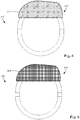
- Figures 11A and 11B illustrate one embodiment of a tube-shaped shield 1170 disposed within a header 1150 of a control module 1102 around one or more conductive assemblies 1144 that are arranged to each receive a proximal end of a lead or lead extension.
- the shield 1170 is illustrated with a circular cross-section, it will be recognized that shields with other cross-sections, such as square, rectangular, oval, triangular, octagonal, or hexagonal, can be used.
- the shield 1170 is typically made of metal, alloy, or any other suitable conductive material. In at least some embodiments, the shield 1170 is a solid tube. In other embodiments, the shield 1170 is a mesh. Optionally, the shield 1170 may extend to either one end or both ends of the header 1150 to provide a tissue connection to the shield 1170 when the control module 1102 is implanted. This tissue connection may facilitate dissipation of currents induced in the shield.
- Figure 12 illustrates another embodiment in which the shield 1270 is divided into several parts disposed between the contacts 1216 of the conductive assemblies 1244.
- the shield 1270 is disposed over the portions of the leads with conductive wires which are the most likely to be adversely affected by RF irradiation.
- the conductive contacts on the lead and the contact 1216 of the control module will shield the lead to at least some extent.
- the shield 1270 is typically made of metal, alloy, or any other suitable conductive material. In at least some embodiments, the shield 1270 is a solid tube. In other embodiments, the shield 1270 is a mesh.
- shields 1170, 1270 can optionally be coupled conductively or capacitively to a conductive structure disposed on a surface of the body of the control module, as disclosed with respect to the embodiments illustrated in Figures 9 , 10A, and 10B .
- the shields described above can be adapted for use with a connector assembly of a lead extension or any other connector assembly of another component of the electrical stimulation system.
- Figure 13 illustrates one embodiment of a lead extension 1324 having a connector assembly 1322 with a shield 1370 disposed over at least a portion of the connector assembly leaving the port 1330 open to receive one or more leads.
- the shield 1370 is conductive and can be similar in materials to any of the shield embodiments described above with respect to Figures 4-8 .
- the shield 1370 can be formed of a sheet, foil, mesh, or layer of conductive material disposed on the surface of the connector assembly 1322.
- the shield 1370 may include a window (not shown) for viewing at least a portion of the lead(s) inserted into the connector assembly 1322.
- the shield 1370 may have a frequency selective surface or a patterned arrangement with, for example, stripes or slats.
- the shield 1370 may be formed by doping or impregnating polymeric material of the connector assembly with conductive material.
- Figure 14 illustrates another embodiment of a shield 1470 for using with a lead extension 1424 having a connector assembly 1422.
- the shield 1470 is a tube-shaped element disposed within connector assembly 1422 and around at least a portion of the connector assembly 1422 that receives the lead(s).
- the shield 1370 is conductive and can be similar in materials to any of the shield embodiments described above with respect to Figures 11A-12 .
- the shield may be a single tube-shaped element or multiple tube-shaped elements spaced apart from each other.
- FIG. 15 is a schematic overview of one embodiment of components of an electrical stimulation system 1500 including an electronic subassembly 1510 disposed within a control module. It will be understood that the electrical stimulation system can include more, fewer, or different components and can have a variety of different configurations including those configurations disclosed in the stimulator references cited herein.
- power source 1512 can be used including, for example, a battery such as a primary battery or a rechargeable battery.
- a battery such as a primary battery or a rechargeable battery.
- other power sources include super capacitors, nuclear or atomic batteries, mechanical resonators, infrared collectors, thermally-powered energy sources, flexural powered energy sources, bioenergy power sources, fuel cells, bioelectric cells, osmotic pressure pumps, and the like including the power sources described in U.S. Patent No. 7,437,193 , incorporated herein by reference.
- power can be supplied by an external power source through inductive coupling via the optional antenna 1518 or a secondary antenna.
- the external power source can be in a device that is mounted on the skin of the user or in a unit that is provided near the user on a permanent or periodic basis.
- the battery may be recharged using the optional antenna 1518, if desired. Power can be provided to the battery for recharging by inductively coupling the battery through the antenna to a recharging unit 1516 external to the user. Examples of such arrangements can be found in the references identified above.
- electrical current is emitted by the electrodes 134 on the paddle or lead body to stimulate nerve fibers, muscle fibers, or other body tissues near the electrical stimulation system.
- a processor 1504 is generally included to control the timing and electrical characteristics of the electrical stimulation system. For example, the processor 1504 can, if desired, control one or more of the timing, frequency, strength, duration, and waveform of the pulses. In addition, the processor 1504 can select which electrodes can be used to provide stimulation, if desired. In some embodiments, the processor 1504 may select which electrode(s) are cathodes and which electrode(s) are anodes. In some embodiments, the processor 1504 may be used to identify which electrodes provide the most useful stimulation of the desired tissue.
- Any processor can be used and can be as simple as an electronic device that, for example, produces pulses at a regular interval or the processor can be capable of receiving and interpreting instructions from an external programming unit 1508 that, for example, allows modification of pulse characteristics.
- the processor 1504 is coupled to a receiver 1502 which, in turn, is coupled to the optional antenna 1518. This allows the processor 1504 to receive instructions from an external source to, for example, direct the pulse characteristics and the selection of electrodes, if desired.
- the antenna 1518 is capable of receiving signals (e.g ., RF signals) from an external telemetry unit 1506 which is programmed by a programming unit 1508.
- the programming unit 1508 can be external to, or part of, the telemetry unit 1506.
- the telemetry unit 1506 can be a device that is worn on the skin of the user or can be carried by the user and can have a form similar to a pager, cellular phone, or remote control, if desired.
- the telemetry unit 1506 may not be worn or carried by the user but may only be available at a home station or at a clinician's office.
- the programming unit 1508 can be any unit that can provide information to the telemetry unit 1506 for transmission to the electrical stimulation system 1500.
- the programming unit 1508 can be part of the telemetry unit 1506 or can provide signals or information to the telemetry unit 1506 via a wireless or wired connection.
- One example of a suitable programming unit is a computer operated by the user or clinician to send signals to the telemetry unit 1506.
- the signals sent to the processor 1504 via the antenna 1518 and receiver 1502 can be used to modify or otherwise direct the operation of the electrical stimulation system.
- the signals may be used to modify the pulses of the electrical stimulation system such as modifying one or more of pulse duration, pulse frequency, pulse waveform, and pulse strength.
- the signals may also direct the electrical stimulation system 1500 to cease operation, to start operation, to start charging the battery, or to stop charging the battery.
- the stimulation system does not include an antenna 1518 or receiver 1502 and the processor 1504 operates as programmed.
- the electrical stimulation system 1500 may include a transmitter (not shown) coupled to the processor 1504 and the antenna 1518 for transmitting signals back to the telemetry unit 1506 or another unit capable of receiving the signals.
- the electrical stimulation system 1500 may transmit signals indicating whether the electrical stimulation system 1500 is operating properly or not or indicating when the battery needs to be charged or the level of charge remaining in the battery.
- the processor 1504 may also be capable of transmitting information about the pulse characteristics so that a user or clinician can determine or verify the characteristics.
Description
- The present invention is directed to implantable electrical stimulation leads having a shield on the header of a control module, or to a lead extension having a shield on the connector assembly.
- Implantable electrical stimulation systems have proven therapeutic in a variety of diseases and disorders. For example, spinal cord stimulation systems have been used as a therapeutic modality for the treatment of chronic pain syndromes. Peripheral nerve stimulation has been used to treat incontinence, as well as a number of other applications under investigation. Functional electrical stimulation systems have been applied to restore some functionality to paralyzed extremities in spinal cord injury patients.
- Stimulators have been developed to provide therapy for a variety of treatments. A stimulator can include a control module (with a pulse generator), one or more leads, and an array of stimulator electrodes on each lead. The stimulator electrodes are in contact with or near the nerves, muscles, or other tissue to be stimulated. The pulse generator in the control module generates electrical pulses that are delivered by the electrodes to body tissue.
- Conventional implanted electrical stimulation systems are often incompatible with magnetic resonance imaging ("MRI") due to the large radio frequency ("RF") pulses used during MRI. The RF pulses can generate transient signals in the conductors and electrodes of an implanted lead. These signals can have deleterious effects including, for example, unwanted heating of the tissue causing tissue damage, induced currents in the lead, or premature failure of electronic components.
- An implantable control module with a conductive shield over at least a portion of the header is known from
US2008/0039898 A1 . - A tube-shaped shielding element disposed within the connector assembly of a medical lead extension is disclosed in
US2012/0130461 A1 . - The present invention is defined in the
independent claims 1 and 7 with preferred embodiments according to the claims dependent thereon. - Non-limiting and non-exhaustive embodiments of the present invention are described with reference to the following drawings. In the drawings, like reference numerals refer to like parts throughout the various figures unless otherwise specified.
- For a better understanding of the present invention, reference will be made to the following Detailed Description, which is to be read in association with the accompanying drawings, wherein:
-
FIG. 1 is a schematic view of one embodiment of an electrical stimulation system that includes a paddle body coupled to a control module via lead bodies, according to the invention; -
FIG. 2 is a schematic view of another embodiment of an electrical stimulation system that includes a percutaneous lead body coupled to a control module via a lead body, according to the invention; -
FIG. 3A is a schematic view of one embodiment of a plurality of connector assemblies disposed in the control module ofFIG. 1 , the connector assemblies configured and arranged to receive the proximal portions of the lead bodies ofFIG. 1 , according to the invention; -
FIG. 3B is a schematic view of one embodiment of a connector assembly disposed in the control module ofFIG. 2 , the connector assembly configured and arranged to receive the proximal portion of one of the lead body ofFIG. 2 , according to the invention; -
FIG. 3C is a schematic view of one embodiment of a proximal portion of the lead body ofFIG. 2 , a lead extension, and the control module ofFIG. 2 , the lead extension configured and arranged to couple the lead body to the control module, according to the invention; -
FIG. 4 is a schematic side view of one embodiment of a control module with a shield disposed over the header, according to the invention; -
FIG. 5A is a schematic side view of one embodiment of a control module with a shield disposed over the header, where the shield defines a window surrounded on all sides of its perimeter by the shield, according to the invention; -
FIG. 5B is a schematic side view of one embodiment of a control module with a shield disposed over the header, where the shield defines a window surrounded on only some of the sides of its perimeter by the shield, according to the invention; -
FIG. 6 is a schematic side view of one embodiment of a control module with a shield disposed over the header, where the shield has a frequency selective surface, according to the invention; -
FIG. 7 is a schematic side view of one embodiment of a control module with a patterned shield disposed over the header, according to the invention; -
FIG. 8 is a schematic side view of one embodiment of a control module with a shield formed by doping or impregnating plastic material of the header with a conductive material, according to the invention; -
FIG. 9 is a schematic side view of one embodiment of a control module with a shield disposed over the header and conductively coupled to a conductive structure disposed on the body of the control module, according to the invention; -
FIG. 10A is a schematic front view of the lead-receiving side of one embodiment of a control module with a shield disposed over the header and capacitively coupled via a solid dielectric material to a conductive structure disposed on the body of the control module, according to the invention; -
FIG. 10B is a schematic front view of a portion of the lead-receiving side or one embodiment of a control module with a shield disposed over the header and capacitively coupled via a discrete capacitor to a conductive structure disposed on the body of the control module, according to the invention; -
FIG. 11A is a schematic side view of one embodiment of a control module with a tube-shaped shield disposed within the header, according to the invention; -
FIG. 11B is a schematic front view of a portion of the lead-receiving side of one embodiment of the control module ofFIG. 11A with the tube-shaped shield, according to the invention; -
FIG. 12 is a schematic side view of one embodiment of a control module with a tube-shaped shield, formed in multiple parts, disposed within the header, according to the invention; -
FIG. 13 is a schematic side view of one embodiment of a connector assembly of a lead extension with shield disposed around the connector assembly, according to the invention; -
FIG. 14 is a schematic side view of one embodiment of a connector assembly of a lead extension with a tube-shaped shield disposed within the connector assembly, according to the invention; -
FIG. 15 is a schematic overview of one embodiment of components of a stimulation system, including an electronic subassembly disposed within a control module, according to the invention. - The present invention is directed to the area of implantable electrical stimulation systems. Also disclosed are methods of making and using the systems. There is also disclosed an implantable electrical stimulation leads having a shield on or within the header of a control module, as well as methods of making and using the leads and electrical stimulation systems.
- Suitable implantable electrical stimulation systems include, but are not limited to, an electrode lead ("lead") with one or more electrodes disposed on a distal end of the lead and one or more terminals disposed on one or more proximal ends of the lead. Leads include, for example, percutaneous leads, paddle leads, and cuff leads. Examples of electrical stimulation systems with leads are found in, for example,
U.S. Patents Nos. 6,181,969 ;6,516,227 ;6,609,029 ;6,609,032 ;6,741,892 ;7,244,150 ;7,672,734 ;7,761,165 ;7,949,395 ;7,974,706 ;8,175,710 ;8,224,450 ; and8,364,278 ; andU.S. Patent Application Publication No. 2007/0150036 . -
Figure 1 illustrates schematically one embodiment of anelectrical stimulation system 100. The electrical stimulation system includes a control module (e.g., a stimulator or pulse generator) 102, apaddle body 104, and one ormore lead bodies 106 coupling thecontrol module 102 to thepaddle body 104. Thepaddle body 104 and the one ormore lead bodies 106 form a lead. Thepaddle body 104 typically includes an array ofelectrodes 134. Thecontrol module 102 typically includes anelectronic subassembly 110 and anoptional power source 120 disposed in a sealedbody 114. InFigure 1 , twolead bodies 106 are shown coupled to thecontrol module 102. - The
control module 102 typically includes one ormore connector assemblies 144 into which the proximal end of the one or morelead bodies 106 can be plugged to make an electrical connection via connector contacts (e.g., 316 inFigures 3A-3B ; and 340 ofFigure 3C ) disposed in theconnector assembly 144 and terminals (e.g., 310 inFigures 3A-3C ) on each of the one or morelead bodies 106. The connector contacts are coupled to theelectronic subassembly 110 and the terminals are coupled to theelectrodes 134. InFigure 1 , twoconnector assemblies 144 are shown. - The one or
more connector assemblies 144 may be disposed in aheader 150. Theheader 150 provides a protective covering over the one ormore connector assemblies 144. Theheader 150 may be formed using any suitable process including, for example, casting, molding (including injection molding), and the like. In addition, one or more lead extensions 324 (seeFigure 3C ) can be disposed between the one or morelead bodies 106 and thecontrol module 102 to extend the distance between the one or morelead bodies 106 and thecontrol module 102. - It will be understood that the electrical stimulation system can include more, fewer, or different components and can have a variety of different configurations including those configurations disclosed in the electrical stimulation system references cited herein. For example, instead of a
paddle body 104, theelectrodes 134 can be disposed in an array at or near the distal end of thelead body 106 forming a percutaneous lead, as illustrated inFigure 2 . A percutaneous lead may be isodiametric along the length of thelead body 106. - The electrical stimulation system or components of the electrical stimulation system, including one or more of the
lead bodies 106, thecontrol module 102, and, in the case of a paddle lead, thepaddle body 104, are typically implanted into the body of a patient. The electrical stimulation system can be used for a variety of applications including, but not limited to, spinal cord stimulation, brain stimulation, neural stimulation, muscle stimulation, cardiac stimulation, and the like. - The
electrodes 134 can be formed using any conductive, biocompatible material. Examples of suitable materials include metals, alloys, conductive polymers, conductive carbon, and the like, as well as combinations thereof. In at least some embodiments, one or more of theelectrodes 134 are formed from one or more of: platinum, platinum iridium, palladium, titanium, or rhenium. - The number of
electrodes 134 in the array ofelectrodes 134 may vary. For example, there can be two, three, four, five, six, seven, eight, nine, ten, eleven, twelve, thirteen, fourteen, fifteen, sixteen, ormore electrodes 134. As will be recognized, other numbers ofelectrodes 134 may also be used. As will be recognized, other numbers ofelectrodes 134 may also be used. InFigure 1 , sixteenelectrodes 134 are shown. Theelectrodes 134 can be formed in any suitable shape including, for example, round, oval, triangular, rectangular, pentagonal, hexagonal, heptagonal, octagonal, or the like. - The electrodes of the
paddle body 104 or one or morelead bodies 106 are typically disposed in, or separated by, a non-conductive, biocompatible material including, for example, silicone, polyurethane, and the like or combinations thereof. Thepaddle body 104 and one or morelead bodies 106 may be formed in the desired shape by any process including, for example, molding (including injection molding), casting, and the like. Electrodes and connecting wires can be disposed onto or within a paddle body either prior to or subsequent to a molding or casting process. The non-conductive material typically extends from the distal end of the lead to the proximal end of each of the one or morelead bodies 106. The non-conductive, biocompatible material of thepaddle body 104 and the one or morelead bodies 106 may be the same or different. Thepaddle body 104 and the one or morelead bodies 106 may be a unitary structure or can be formed as two separate structures that are permanently or detachably coupled together. - Terminals (e.g., 310 in
Figures 3A-3C ) are typically disposed at the proximal end of the one or morelead bodies 106 for connection to corresponding conductive contacts (e.g., 316 inFigures 3A-3B ; and 340 ofFigure 3C ) in connector assemblies (e.g., 144 inFigures 1-3C ) disposed on, for example, the control module 102 (or to other devices, such as conductive contacts on a lead extension, an operating room cable, a splitter, an adaptor, or the like). - Conductive wires (not shown) extend from the terminals (e.g., 310 in
Figures 3A-3C ) to theelectrodes 134. Typically, one ormore electrodes 134 are electrically coupled to a terminal (e.g., 310 inFigures 3A-3C ). In some embodiments, each terminal (e.g., 310 inFigures 3A-3C ) is only coupled to oneelectrode 134. - The conductive wires may be embedded in the non-conductive material of the lead or can be disposed in one or more lumens (not shown) extending along the lead. In some embodiments, there is an individual lumen for each conductive wire. In other embodiments, two or more conductive wires may extend through a lumen. There may also be one or more lumens (not shown) that open at, or near, the proximal end of the lead, for example, for inserting a stylet rod to facilitate placement of the lead within a body of a patient. Additionally, there may also be one or more lumens (not shown) that open at, or near, the distal end of the lead, for example, for infusion of drugs or medication into the site of implantation of the
paddle body 104. In at least one embodiment, the one or more lumens may be flushed continually, or on a regular basis, with saline, epidural fluid, or the like. In at least some embodiments, the one or more lumens can be permanently or removably sealable at the distal end. - As discussed above, the one or more
lead bodies 106 may be coupled to the one ormore connector assemblies 144 disposed on thecontrol module 102. Thecontrol module 102 can include any suitable number ofconnector assemblies 144 including, for example, two three, four, five, six, seven, eight, ormore connector assemblies 144. It will be understood that other numbers ofconnector assemblies 144 may be used instead. InFigure 1 , each of the twolead bodies 106 includes eight terminals that are shown coupled with eight conductive contacts disposed in a different one of twodifferent connector assemblies 144. - In at least some embodiments, leads are coupled to connectors disposed on control modules.
Figure 3A is a schematic perspective view of one embodiment of asingle connector assembly 144 disposed on thecontrol module 102.Figure 3B is a schematic perspective view of one embodiment of a plurality ofconnector assemblies 144 disposed on thecontrol module 102. In at least some embodiments, thecontrol module 102 includes twoconnector assemblies 144. In at least some embodiments, thecontrol module 102 includes fourconnector assemblies 144. - In
Figures 3A and 3B , the proximal ends 306 of one or morelead bodies 106 are shown configured and arranged for insertion to thecontrol module 102. InFigures 3A and 3B , the one ormore connector assemblies 144 are disposed in theheader 150. In at least some embodiments, theheader 150 defines one ormore ports 304 into which aproximal end 306 of the one or morelead bodies 106 withterminals 310 can be inserted, as shown bydirectional arrows 312, in order to gain access to the connector contacts disposed in the one ormore connector assemblies 144. - The one or
more connector assemblies 144 each include aconnector housing 314 and a plurality ofconnector contacts 316 disposed therein. Typically, theconnector housing 314 defines a port (not shown) that provides access to the plurality ofconnector contacts 316. In at least some embodiments, one or more of theconnector assemblies 144 further includes a retainingelement 318 configured and arranged to fasten the corresponding lead body 308 to theconnector assembly 144 when thelead body 106 is inserted into theconnector assembly 144 to prevent undesired detachment of thelead body 106 from theconnector assembly 144. For example, the retainingelement 318 may include an aperture through which a fastener (e.g., a set screw, pin, or the like) may be inserted and secured against an inserted lead body or lead extension. - When the one or more
lead bodies 106 are inserted into the one ormore ports 304, theconnector contacts 316 can be aligned with theterminals 310 disposed on the one or morelead bodies 106 to electrically couple thecontrol module 102 to the electrodes (134 ofFigure 1 ) disposed at a distal end of the one or morelead bodies 106. Examples of connector assemblies in control modules are found in, for example,U.S. Patent No. 7,244,150 and8,224,450 , which are incorporated by reference. - In
Figure 3C , a leadextension connector assembly 322 is disposed on alead extension 324. The leadextension connector assembly 322 is shown disposed at adistal end 326 of thelead extension 324. The leadextension connector assembly 322 includes acontact housing 328. Thecontact housing 328 defines at least oneport 330 into which aproximal end 306 of thelead body 106 withterminals 310 can be inserted, as shown bydirectional arrow 338. The leadextension connector assembly 322 also includes a plurality ofconnector contacts 340. When thelead body 106 is inserted into theport 330, theconnector contacts 340 disposed in thecontact housing 328 can be aligned with theterminals 310 on thelead body 106 to electrically couple thelead extension 324 to the electrodes (134 ofFigure 1 ) disposed at a distal end (not shown) of thelead body 106. - The proximal end of a lead extension can be similarly configured and arranged as a proximal end of a lead body. The
lead extension 324 may include a plurality of conductive wires (not shown) that electrically couple theconnector contacts 340 to aproximal end 348 of thelead extension 324 that is opposite to thedistal end 326. The conductive wires disposed in thelead extension 324 can be electrically coupled to a plurality of terminals (not shown) disposed on theproximal end 348 of thelead extension 324. In at least some embodiments, theproximal end 348 of thelead extension 324 is configured and arranged for insertion into a lead extension connector assembly disposed in another lead extension. In other embodiments (as shown inFigure 3C ), theproximal end 348 of thelead extension 324 is configured and arranged for insertion into theconnector assembly 144 disposed on thecontrol module 102. - Conventional electrical stimulation systems may be potentially unsate for use with magnetic resonance imaging ("MRI") due to the effects of electromagnetic fields (e.g., radio frequency fields and magnetic field gradients) in an MRI environment. A common mechanism for causing the electrical interactions between the electrical stimulation system and radiofrequency ("RF") irradiation is common-mode coupling of the applied electromagnetic fields that act as a series of distributed sources along elongated conductive structures, such as leads, or conductors within leads. Common-mode induced RF currents can reach amplitudes of greater than one ampere in MRI environments. Such currents can cause heating and potentially disruptive voltages within electronic circuits, such as electronic circuits disposed within the electronic subassembly.
- Some of the effects of RF irradiation may include, for example, inducing current in the lead, causing undesired heating around the lead that may potentially cause tissue damage, undesired or unexpected operation of electronic components, or damage to, or premature failure of, electronic components. Additionally, when an electrical stimulation system is used within an MRI scanner environment, the electrical interactions between the electrical stimulation system and the MRI may cause distortions in images formed by the MRI system.
- When the lead is exposed to electromagnetic fields, RF energy may be induced along the length of the lead. It has been found that in many instances a major portion of the RF energy induced in the lead occurs in the distal and proximal ends of the lead. When the lead is coupled to the control module, at least some of the RF energy induced along the lead may propagate from the lead to the control module. The RF energy may, for example, propagate between the terminals of the lead and the connector contacts of the connector assembly of the control module. Once the induced RF energy reaches the control module, the RF energy may propagate along a plurality of different conductive paths to the electronic subassembly.
- In addition, it has been found that local heating may occur in tissue near the junction between the
header 150 and sealedbody 114 of the control module 102 (see,Figure 2 ), particularly when the exterior of the sealed body is made of metal (e.g., titanium) or metalized and theheader 150 is made of a non-conductive material (e.g., medical grade epoxy or polyurethane). It is believed that the discontinuity in the dielectric constant and conductivity between the tissue and the header may cause electromagnetic fields and currents to build up especially near the header-tissue-sealed body interface and cause local heating (e.g., "hotspots") in the adjacent tissue. - Shielding of at least a portion of the header of the control module can reduce the current induced in attached leads and delivered to the control module. It is also believed that the shielding may reduce or eliminate the dielectric discontinuity between the header and the tissue resulting in lower or more homogenous tissue heating.
- A variety of different shield arrangements can be used.
Figure 4 illustrates one arrangement with ametal shield 470 disposed over at least a portion of theheader 450 of thecontrol module 402. Theshield 470 does not extend over the ports 304 (FIG. 3A ) that receive the leads (or lead extensions). Theshield 470 can be made of any suitable biocompatible material such as metals or alloys, including, but not limited to, copper, stainless steel, titanium, and the like. Theshield 470 may take the form of, for example, a solid sheet or foil of material, a mesh, or a layer of conductive material formed (for example, by physical or chemical deposition) on the control module or on a substrate (for example, a polymeric substrate) disposed on the header, or any combination thereof. - In at least some embodiments, the
shield 470 may be removable from thecontrol module 402. In at least some embodiments, theshield 470 may be permanently or temporarily affixed to thecontrol module 402. Affixation can be accomplished using, for example, adhesive, soldering, welding, brazing, press fitting, or any other suitable affixation method or medium. - In at least some embodiments, the
shield 470 may be attached to thecontrol module 402 as part of the manufacture of the control module. In some embodiments, the shield may be attached or otherwise coupled to the control module after manufacture of the control module. In some embodiments, a shield may be arranged to retrofit an existing control module or as an optional component for the control module. - In at least some embodiments, the shield 470 (or any of the other shields described herein) may be coupled to the electronic subassembly 110 (
Figure 1 ) of the control module 402 (for example, coupled to interconnects that extend between the header and the sealed body) so that theshield 470 can act as a return electrode in combination with one or more of the electrodes on the lead. The sealed body 114 (Figure 1 ) of the control module may be non-conductive. - In at least some embodiments, the shield may include a window to allow a practitioner to view a portion of the lead(s) inserted into the header to verify insertion or alignment of the lead(s) within the control module using visual or imaging (e.g., x-ray imaging) techniques.
Figure 5A illustrates one embodiment of ashield 570 with at least onewindow 575 and disposed on aheader 550 of acontrol module 502. The proximal ends of theleads 506 are visible through thewindow 575, as are the conductive contacts 516 of theheader 550. Awindow 575 may be provided on only one side of theshield 570 or on both opposing sides of the shield. Thewindow 575 may have any suitable regular or irregular shape including, but not limited to, square, rectangular, circular, oval, triangular, and the like. In this embodiment, the perimeter of thewindow 575 is defined on all sides by theshield 570. -
Figure 5B illustrates another embodiment of ashield 570 with at least onewindow 575 and disposed on aheader 550 of acontrol module 502. In this embodiment, thewindow 575 can be a cutout portion of theshield 570 where less than the entire perimeter of thewindow 575 is surrounded by theshield 570. It will be understood that, despite being described as a "cutout", thewindow 575 is not necessarily cut out of the shield, but that the shield may be initially formed with the window. In this context, the term "window" is used to indicate that theshield 570 does not cover the entire header, but rather leaves a portion of the header uncovered so that the practitioner can observe a portion of the lead(s) through the window. - It will be recognized that a shield may include more than one window. It will also be recognized that a window in the shield may be provided for some purpose other than observation of the lead(s) inserted into the header of the control module. It will also be recognized that one or more windows may be incorporated in any of the other embodiments of a shield discussed below.
- In another embodiment, illustrated in
Figure 6 , ashield 670 is formed on, or disposed over, theheader 650 of acontrol module 602. Theshield 670 includes a surface that is structured as a frequency selective surface. Frequency selective surfaces, and methods of making such surfaces, are known. At least some embodiments of a frequency selective surface include two-dimensional periodic arrays of metallic elements with specific geometric shapes or arrangements (or both) formed on a substrate (such as a polymeric substrate or the surface of the header 650). In other embodiments, the frequency selective surface is a two-dimensional array of apertures in a metallic sheet or foil with the apertures having specific geometric shapes or arrangements (or both). - The period and shape (or other parameters, such as thickness) of the metallic elements or apertures can be selected and tuned to a particular frequency or to two or more frequencies or to one or more bands of frequencies. For example, a
shield 670 may have a frequency selective surface that is tuned to one or more expected RF frequencies used in MRI procedures such as, for example, 64 MHz or 128 MHz (or both) to attenuate transmission of the electromagnetic energy at the tuned frequency or frequencies into the header. Electromagnetic energy at other frequencies will be less attenuated by the shield or not attenuated at all. - Such a
shield 670 may be desirable as, at least in some embodiments, it allows low frequency signals, such as telemetry signals which may be used to operate, reprogram, or otherwise communicate with the control module, to be received by the control module while at least partially shielding from RF frequencies used in MRI procedures. - In at least some embodiments, the frequency selective surface may be formed directly on the header of the control module, for example, as a patterned layer formed on the control module using deposition and photolithographic or other patterning techniques. In at least some embodiments, the frequency selective surface may be formed on a substrate, such as a polymer substrate, which is then placed over at least a portion of the header of the control module.
- Other patterned shields can be useful. For example, a shield may include a series of slats, stripes or other thin structures to shield electromagnetic fields that are not parallel to these structures.
Figure 7 illustrates one embodiment of ashield 770 disposed on aheader 750 of acontrol module 702. Theshield 770 includes multiple elongatedconductive structures 772, such as slats or stripes. In at least some embodiments, these elongateconductive structures 772 are arranged to extend parallel one or more lead(s) inserted in thecontrol module 702. The width, thickness, material, or other parameters of the elongated structures may be uniform or non-uniform. - The width, thickness, material, or other parameters of the elongated structures, or any combination thereof, may be selected to facilitate shielding of electromagnetic radiation having a particular orientation or polarization (e.g., polarized perpendicular to the elongated structures) or orientations or a particular frequency or frequencies. It will be understood that, in at least some embodiments, the
shield 770 may preferentially reflect or absorb one polarization of electromagnetic radiation and preferentially transmit another polarization of the electromagnetic radiation. - In at least some embodiments, the
elongated structures 772 may be formed directly on theheader 750 of thecontrol module 770, for example, as a patterned layer formed on the control module using deposition and photolithographic or other patterning techniques. In at least some embodiments, theelongated structures 772 may be formed on a substrate, such as a polymer substrate, which is then placed over at least a portion of the header of the control module. - In another embodiment, the plastic material of the header, or a portion of the plastic material of the header, includes a doping or impregnating conductive material that renders that plastic material conductive and able to shield RF energy.
Figure 8 illustrates one embodiment of aheader 850 of acontrol module 802 where the header includes a plastic material that is doped or impregnated with a conductive material to render the plastic material conductive to shield from RF energy. Examples of suitable conductive material for doping or impregnating the plastic material include, but are not limited to, metal or alloy particles or conductive carbon particles or conductive polymers. The plastic material can be any suitable plastic material such as, for example, silicone, polyurethane, or polyetheretherketone. The doped or impregnated plastic material preferably extends through at least the portion of the header surrounding the conductive assembly or conductive assemblies 144 (Figure 1 ) into which the lead(s) are to be inserted. Preferably, the doped or impregnated plastic material does not conductively couple to any of the contacts within the conductive assembly otherwise it may short the contacts and affect stimulation signal delivery. - In any of the embodiments described herein, a shield disposed on or in the header may be electrically coupled to a conductive structure, such as an electrode, disposed, or otherwise formed, on the surface of the body of the control module. In at least some embodiments, this conductive structure is an electrode that is coupled to the electronic subassembly 110 (
Figure 1 ) disposed within the body of the control module. This electrode may, for example, act as a return electrode in conjunction with one or more electrodes on the leads 106 (Figure 1 ). -
Figure 9 illustrates one embodiment of ashield 970, disposed on aheader 950 of acontrol module 902, that is electrically coupled to aconductive structure 980 disposed on thebody 914 of the control module. In the illustrated embodiment ofFigure 9 , aconductive element 974 conductively couples theshield 970 to theconductive structure 980. - In at least some embodiments, the
conductive structure 980 is a case of thebody 914 of thecontrol module 902 and extends around the entire body of the control module. In other embodiments, theconductive structure 980 is formed only on a portion of the surface of thebody 914 of thecontrol module 902. - Although
Figure 9 illustrates contact between the shield and conductive structure at asingle point 974, it will be understood that contact between the shield and conductive structure can be made at multiple points or over one or more elongated regions. In at least one embodiment, contact between the shield and the conductive structure on the body of the control module can be made circumferentially around the entire circumference of the control module (assuming that both the shield and conductive structure extend circumferentially around the entire circumference of the control module) or around at least 50%, 60%, 70%, 75%, 80%, 90%, or more of the circumference of the control module. - Alternatively, the shield can be capacitively, instead of conductively, coupled to the conductive structure on the body of the control module.
Figure 10A illustrates one embodiment of ashield 1070 that is disposed over aheader 1050 of acontrol module 1002. Thebody 1014 of the control module includes aconductive structure 1080, such as an electrode. Asolid dielectric material 1084a is disposed between theshield 1070 and theconductive structure 1080 so that the shield and conductive structure are capacitively coupled. Any of the specific type of material, size, shape, thickness, and dielectric constant of the solid dielectric material, as well as the separation distance and extent of overlap between theshield 1070 andconductive structure 1080, or any combination thereof, may be selected to facilitate shielding from electromagnetic radiation in general or from RF energy having a particular frequency or frequencies or band(s) of frequencies. -
Figure 10B illustrates another embodiment of ashield 1070 that is disposed over aheader 1050 of acontrol module 1002. Thebody 1014 of the control module includes aconductive structure 1080, such as an electrode. Adiscrete capacitor 1084b, or combination of capacitors in parallel or series or any combination thereof, is disposed between theshield 1070 and theconductive structure 1080 so that the shield and conductive structure are capacitively coupled. Any of the capacitance of the capacitor(s) 1084b, as well as the separation distance and extent of overlap between theshield 1070 andconductive structure 1080, or any combination thereof, may be selected to facilitate shielding from electromagnetic radiation in general or from RF energy having particular frequency or frequencies or band(s) of frequencies. - Conductively or capacitively coupling the shield to a conductive structure on the body of the control module may improve the efficiency of the shield to resist penetration of RF energy or reduce magnetic field gradient-induced heating or both. On the other hand, if the shield remains unconnected from any conductive structure on the body of the control module, the shield will not generally couple to the electrodes of the lead(s) which may also be desirable under some circumstances.
- In some embodiments, the shield is disposed within the header instead of over or on the header.
Figures 11A and 11B illustrate one embodiment of a tube-shapedshield 1170 disposed within aheader 1150 of acontrol module 1102 around one or moreconductive assemblies 1144 that are arranged to each receive a proximal end of a lead or lead extension. Although theshield 1170 is illustrated with a circular cross-section, it will be recognized that shields with other cross-sections, such as square, rectangular, oval, triangular, octagonal, or hexagonal, can be used. - The
shield 1170 is typically made of metal, alloy, or any other suitable conductive material. In at least some embodiments, theshield 1170 is a solid tube. In other embodiments, theshield 1170 is a mesh. Optionally, theshield 1170 may extend to either one end or both ends of theheader 1150 to provide a tissue connection to theshield 1170 when thecontrol module 1102 is implanted. This tissue connection may facilitate dissipation of currents induced in the shield. -
Figure 12 illustrates another embodiment in which theshield 1270 is divided into several parts disposed between thecontacts 1216 of theconductive assemblies 1244. When a lead or leads are inserted into the header, theshield 1270 is disposed over the portions of the leads with conductive wires which are the most likely to be adversely affected by RF irradiation. The conductive contacts on the lead and thecontact 1216 of the control module will shield the lead to at least some extent. - The
shield 1270 is typically made of metal, alloy, or any other suitable conductive material. In at least some embodiments, theshield 1270 is a solid tube. In other embodiments, theshield 1270 is a mesh. - It will be understood that
shields Figures 9 ,10A, and 10B . - Alternatively or additionally, the shields described above can be adapted for use with a connector assembly of a lead extension or any other connector assembly of another component of the electrical stimulation system.
Figure 13 illustrates one embodiment of alead extension 1324 having aconnector assembly 1322 with ashield 1370 disposed over at least a portion of the connector assembly leaving theport 1330 open to receive one or more leads. Theshield 1370 is conductive and can be similar in materials to any of the shield embodiments described above with respect toFigures 4-8 . For example, theshield 1370 can be formed of a sheet, foil, mesh, or layer of conductive material disposed on the surface of theconnector assembly 1322. Theshield 1370 may include a window (not shown) for viewing at least a portion of the lead(s) inserted into theconnector assembly 1322. Theshield 1370 may have a frequency selective surface or a patterned arrangement with, for example, stripes or slats. Theshield 1370 may be formed by doping or impregnating polymeric material of the connector assembly with conductive material. -
Figure 14 illustrates another embodiment of ashield 1470 for using with alead extension 1424 having aconnector assembly 1422. Theshield 1470 is a tube-shaped element disposed withinconnector assembly 1422 and around at least a portion of theconnector assembly 1422 that receives the lead(s). Theshield 1370 is conductive and can be similar in materials to any of the shield embodiments described above with respect toFigures 11A-12 . For example, the shield may be a single tube-shaped element or multiple tube-shaped elements spaced apart from each other. -
Figure 15 is a schematic overview of one embodiment of components of anelectrical stimulation system 1500 including anelectronic subassembly 1510 disposed within a control module. It will be understood that the electrical stimulation system can include more, fewer, or different components and can have a variety of different configurations including those configurations disclosed in the stimulator references cited herein. - Some of the components (for example,
power source 1512,antenna 1518,receiver 1502, and processor 1504) of the electrical stimulation system can be positioned on one or more circuit boards or similar carriers within a sealed housing of an implantable pulse generator, if desired. Anypower source 1512 can be used including, for example, a battery such as a primary battery or a rechargeable battery. Examples of other power sources include super capacitors, nuclear or atomic batteries, mechanical resonators, infrared collectors, thermally-powered energy sources, flexural powered energy sources, bioenergy power sources, fuel cells, bioelectric cells, osmotic pressure pumps, and the like including the power sources described inU.S. Patent No. 7,437,193 , incorporated herein by reference. - As another alternative, power can be supplied by an external power source through inductive coupling via the
optional antenna 1518 or a secondary antenna. The external power source can be in a device that is mounted on the skin of the user or in a unit that is provided near the user on a permanent or periodic basis. - If the
power source 1512 is a rechargeable battery, the battery may be recharged using theoptional antenna 1518, if desired. Power can be provided to the battery for recharging by inductively coupling the battery through the antenna to arecharging unit 1516 external to the user. Examples of such arrangements can be found in the references identified above. - In one embodiment, electrical current is emitted by the
electrodes 134 on the paddle or lead body to stimulate nerve fibers, muscle fibers, or other body tissues near the electrical stimulation system. Aprocessor 1504 is generally included to control the timing and electrical characteristics of the electrical stimulation system. For example, theprocessor 1504 can, if desired, control one or more of the timing, frequency, strength, duration, and waveform of the pulses. In addition, theprocessor 1504 can select which electrodes can be used to provide stimulation, if desired. In some embodiments, theprocessor 1504 may select which electrode(s) are cathodes and which electrode(s) are anodes. In some embodiments, theprocessor 1504 may be used to identify which electrodes provide the most useful stimulation of the desired tissue. - Any processor can be used and can be as simple as an electronic device that, for example, produces pulses at a regular interval or the processor can be capable of receiving and interpreting instructions from an
external programming unit 1508 that, for example, allows modification of pulse characteristics. In the illustrated embodiment, theprocessor 1504 is coupled to areceiver 1502 which, in turn, is coupled to theoptional antenna 1518. This allows theprocessor 1504 to receive instructions from an external source to, for example, direct the pulse characteristics and the selection of electrodes, if desired. - In one embodiment, the
antenna 1518 is capable of receiving signals (e.g., RF signals) from anexternal telemetry unit 1506 which is programmed by aprogramming unit 1508. Theprogramming unit 1508 can be external to, or part of, thetelemetry unit 1506. Thetelemetry unit 1506 can be a device that is worn on the skin of the user or can be carried by the user and can have a form similar to a pager, cellular phone, or remote control, if desired. As another alternative, thetelemetry unit 1506 may not be worn or carried by the user but may only be available at a home station or at a clinician's office. Theprogramming unit 1508 can be any unit that can provide information to thetelemetry unit 1506 for transmission to theelectrical stimulation system 1500. Theprogramming unit 1508 can be part of thetelemetry unit 1506 or can provide signals or information to thetelemetry unit 1506 via a wireless or wired connection. One example of a suitable programming unit is a computer operated by the user or clinician to send signals to thetelemetry unit 1506. - The signals sent to the
processor 1504 via theantenna 1518 andreceiver 1502 can be used to modify or otherwise direct the operation of the electrical stimulation system. For example, the signals may be used to modify the pulses of the electrical stimulation system such as modifying one or more of pulse duration, pulse frequency, pulse waveform, and pulse strength. The signals may also direct theelectrical stimulation system 1500 to cease operation, to start operation, to start charging the battery, or to stop charging the battery. In other embodiments, the stimulation system does not include anantenna 1518 orreceiver 1502 and theprocessor 1504 operates as programmed. - Optionally, the
electrical stimulation system 1500 may include a transmitter (not shown) coupled to theprocessor 1504 and theantenna 1518 for transmitting signals back to thetelemetry unit 1506 or another unit capable of receiving the signals. For example, theelectrical stimulation system 1500 may transmit signals indicating whether theelectrical stimulation system 1500 is operating properly or not or indicating when the battery needs to be charged or the level of charge remaining in the battery. Theprocessor 1504 may also be capable of transmitting information about the pulse characteristics so that a user or clinician can determine or verify the characteristics. - The above specification, examples and data provide a description of the manufacture and use of the composition of the invention. Since many embodiments of the invention can be made without departing from the scope of the invention, as defined in the claims hereinafter appended.
Claims (8)
- An implantable control module for an electrical stimulation system, the control module comprising:a sealed body;an electronic subassembly disposed in the sealed body and configured and arranged to generate electrical stimulation signals for delivery through a lead coupled to the implantable control module;a header coupled to the sealed body, the header comprising at least one connector assembly, each connector assembly defining a port with each connector assembly configured and arranged to receive a proximal portion of a lead inserted into the port, the header further comprising a plurality of contacts disposed within each connector assembly and configured and arranged to make contact with terminals disposed on a lead when the lead and terminals are received in the connector assembly and to electrically couple the terminals of the lead to the electronic subassembly; anda conductive shield disposed over at least a portion of the at least one connector assembly of the header, wherein the conductive shield is configured and arranged to hinder generation of current in the header or in a portion of a lead received in the header in response to application of an external radiofrequency (RF) or magnetic field, characterised in that the conductive shield comprises a substrate and a plurality of conductive stripes or conductive slats disposed on the substrate and arranged parallel to the at least one connector assembly, wherein the conductive shield is disposed over at least a portion of the header.
- The control module of claim 1, further comprising a conductive structure disposed on the sealed body and electrically coupled to the electronic subassembly.
- The control module of claim 2, wherein, the conductive shield is conductively coupled to the conductive structure.
- The control module of claim 2, wherein the control module further comprises a solid dielectric material disposed between a portion of the conductive shield and a portion of the conductive structure.
- The control module of claim 2, wherein the control module further comprises a discrete capacitor coupled between the conductive shield and the conductive structure.
- An electrical stimulation system, comprising:the control module of claim 1; anda lead coupleable to the control module, the lead comprising a plurality of electrodes configured and arranged to deliver stimulation signals generated by the control module to patient tissue.
- An implantable lead extension for an electrical stimulation system, the lead extension comprising:an extension body having a proximal end, a distal end, and a longitudinal length;a plurality of conductive contacts disposed along the proximal end of the extension body;a connector assembly disposed on the distal end of the extension body, the connector assembly defining at least one port configured and arranged to receive a proximal portion of a lead inserted into the port, the connector assembly further comprising a plurality of contacts disposed within the connector assembly and configured and arranged to make contact with terminals disposed on a lead when the lead and terminals are received in the connector assembly;a plurality of conductive wires electrically coupling the conductive contacts along the proximal end of the extension body to the contacts of connector assembly; anda conductive shield disposed over at least a portion of the connector assembly, wherein the conductive shield is configured and arranged to hinder generation of current in the connector assembly or in a portion of a lead received in the connector assembly in response to application of an external radiofrequency (RF) or magnetic field, characterised in that the conductive shield comprises a substrate and a plurality of conductive stripes or conductive slats disposed on the substrate and arranged parallel to the at least one connector assembly, wherein the conductive shield is disposed over at least a portion of the connector assembly.
- An electrical stimulation system, comprising:the implantable lead extension of claim 7; anda lead coupleable to the lead extension, the lead comprising a plurality of electrodes.
Applications Claiming Priority (2)
| Application Number | Priority Date | Filing Date | Title |
|---|---|---|---|
| US201261692632P | 2012-08-23 | 2012-08-23 | |
| PCT/US2013/055736 WO2014031606A1 (en) | 2012-08-23 | 2013-08-20 | Implantable electrical stimulation systems with shielded control module and methods for making and using |
Publications (2)
| Publication Number | Publication Date |
|---|---|
| EP2888002A1 EP2888002A1 (en) | 2015-07-01 |
| EP2888002B1 true EP2888002B1 (en) | 2018-02-21 |
Family
ID=49111557
Family Applications (1)
| Application Number | Title | Priority Date | Filing Date |
|---|---|---|---|
| EP13756773.1A Not-in-force EP2888002B1 (en) | 2012-08-23 | 2013-08-20 | Implantable electrical stimulation systems with shielding |
Country Status (4)
| Country | Link |
|---|---|
| US (2) | US9008778B2 (en) |
| EP (1) | EP2888002B1 (en) |
| AU (1) | AU2013305941B2 (en) |
| WO (1) | WO2014031606A1 (en) |
Families Citing this family (17)
| Publication number | Priority date | Publication date | Assignee | Title |
|---|---|---|---|---|
| CN105517627B (en) | 2013-09-06 | 2017-10-10 | 波士顿科学神经调制公司 | Induct the System and method for of heat for reducing the electromagnetic field from implantable impulse generator |
| US10092747B2 (en) * | 2014-05-02 | 2018-10-09 | Nevro Corporation | MRI compatible medical devices |
| US9782581B2 (en) | 2014-06-27 | 2017-10-10 | Boston Scientific Neuromodulation Corporation | Methods and systems for electrical stimulation including a shielded sheath |
| WO2016160423A1 (en) | 2015-03-27 | 2016-10-06 | Boston Scientific Neuromodulation Corporation | Systems and methods for making and using electrical stimulation systems to reduce rf-induced tissue heating |
| WO2016176645A1 (en) * | 2015-04-30 | 2016-11-03 | Boston Scientific Neuromodulation Corporation | Electrical stimulation leads and systems having a rf shield along at least the lead and methods of making and using |
| WO2018080600A1 (en) | 2016-10-31 | 2018-05-03 | The Alfred E. Mann Foundation For Scientific Research | Nerve cuff electrodes fabricated using over-molded lcp substrates |
| WO2019126195A1 (en) * | 2017-12-19 | 2019-06-27 | Cardiac Pacemakers, Inc. | Housing for implantable medical device |
| WO2020172500A1 (en) | 2019-02-21 | 2020-08-27 | Envoy Medical Corporation | Implantable cochlear system with integrated components and lead characterization |
| EP3763416A1 (en) * | 2019-07-11 | 2021-01-13 | BIOTRONIK SE & Co. KG | Dielectric header structure for reducing electromagnetic interference |
| US11564046B2 (en) | 2020-08-28 | 2023-01-24 | Envoy Medical Corporation | Programming of cochlear implant accessories |
| US11806531B2 (en) | 2020-12-02 | 2023-11-07 | Envoy Medical Corporation | Implantable cochlear system with inner ear sensor |
| US11471689B2 (en) | 2020-12-02 | 2022-10-18 | Envoy Medical Corporation | Cochlear implant stimulation calibration |
| US11697019B2 (en) | 2020-12-02 | 2023-07-11 | Envoy Medical Corporation | Combination hearing aid and cochlear implant system |
| US11633591B2 (en) | 2021-02-23 | 2023-04-25 | Envoy Medical Corporation | Combination implant system with removable earplug sensor and implanted battery |
| US11839765B2 (en) | 2021-02-23 | 2023-12-12 | Envoy Medical Corporation | Cochlear implant system with integrated signal analysis functionality |
| US11865339B2 (en) | 2021-04-05 | 2024-01-09 | Envoy Medical Corporation | Cochlear implant system with electrode impedance diagnostics |
| CA3226146A1 (en) | 2021-07-09 | 2023-01-12 | The Alfred E. Mann Foundation For Scientific Research | Electrode leads having multi-application helical nerve cuffs and associated systems and methods |
Family Cites Families (31)
| Publication number | Priority date | Publication date | Assignee | Title |
|---|---|---|---|---|
| US5131388A (en) | 1991-03-14 | 1992-07-21 | Ventritex, Inc. | Implantable cardiac defibrillator with improved capacitors |
| US6181969B1 (en) | 1998-06-26 | 2001-01-30 | Advanced Bionics Corporation | Programmable current output stimulus stage for implantable device |
| US6393325B1 (en) | 1999-01-07 | 2002-05-21 | Advanced Bionics Corporation | Directional programming for implantable electrode arrays |
| US6240317B1 (en) * | 1999-04-30 | 2001-05-29 | Medtronic, Inc. | Telemetry system for implantable medical devices |
| US6516227B1 (en) | 1999-07-27 | 2003-02-04 | Advanced Bionics Corporation | Rechargeable spinal cord stimulator system |
| US7949395B2 (en) | 1999-10-01 | 2011-05-24 | Boston Scientific Neuromodulation Corporation | Implantable microdevice with extended lead and remote electrode |
| US6609029B1 (en) | 2000-02-04 | 2003-08-19 | Advanced Bionics Corporation | Clip lock mechanism for retaining lead |
| US6741892B1 (en) | 2000-03-10 | 2004-05-25 | Advanced Bionics Corporation | Movable contact locking mechanism for spinal cord stimulator lead connector |
| US6510345B1 (en) | 2000-04-24 | 2003-01-21 | Medtronic, Inc. | System and method of bridging a transreceiver coil of an implantable medical device during non-communication periods |
| US8364278B2 (en) | 2002-01-29 | 2013-01-29 | Boston Scientific Neuromodulation Corporation | Lead assembly for implantable microstimulator |
| US7132173B2 (en) | 2002-06-28 | 2006-11-07 | Advanced Bionics Corporation | Self-centering braze assembly |
| SE0400849D0 (en) * | 2004-03-30 | 2004-03-30 | St Jude Medical | Implantable Medical Device |
| EP1753505B1 (en) | 2004-05-28 | 2009-10-07 | St. Jude Medical AB | Implantable medical device |
| US7761165B1 (en) | 2005-09-29 | 2010-07-20 | Boston Scientific Neuromodulation Corporation | Implantable stimulator with integrated plastic housing/metal contacts and manufacture and use |
| US8233985B2 (en) | 2005-11-04 | 2012-07-31 | Kenergy, Inc. | MRI compatible implanted electronic medical device with power and data communication capability |
| US8700178B2 (en) | 2005-12-27 | 2014-04-15 | Boston Scientific Neuromodulation Corporation | Stimulator leads and methods for lead fabrication |
| US7672734B2 (en) | 2005-12-27 | 2010-03-02 | Boston Scientific Neuromodulation Corporation | Non-linear electrode array |
| US7244150B1 (en) | 2006-01-09 | 2007-07-17 | Advanced Bionics Corporation | Connector and methods of fabrication |
| US8175710B2 (en) | 2006-03-14 | 2012-05-08 | Boston Scientific Neuromodulation Corporation | Stimulator system with electrode array and the method of making the same |
| US7974706B2 (en) | 2006-03-30 | 2011-07-05 | Boston Scientific Neuromodulation Corporation | Electrode contact configurations for cuff leads |
| US8224450B2 (en) | 2006-09-18 | 2012-07-17 | Boston Scientific Neuromodulation Corporation | Feed through interconnect assembly for an implantable stimulation system and methods of making and using |
| US7620453B1 (en) * | 2006-10-20 | 2009-11-17 | Pacesetter, Inc. | Implantable medical device with improved EMI filter |
| US7751880B1 (en) * | 2007-02-12 | 2010-07-06 | Pacesetter, Inc. | Shielded electrode assembly for effective nerve sensing and stimulation |
| US7822484B1 (en) | 2007-04-03 | 2010-10-26 | Pacesetter, Inc. | MRI-compatible implantable lead having high impedance electrodes |
| US8103347B2 (en) * | 2007-04-25 | 2012-01-24 | Advanced Neuromodulation Systems, Inc. | Implantable pulse generator comprising MRI current limiting windings in header structure |
| US8032228B2 (en) | 2007-12-06 | 2011-10-04 | Cardiac Pacemakers, Inc. | Method and apparatus for disconnecting the tip electrode during MRI |
| EP2429631B1 (en) * | 2009-04-30 | 2014-09-10 | Medtronic, Inc. | Termination of a shield within an implantable medical lead |
| US8457756B2 (en) | 2009-11-11 | 2013-06-04 | Boston Scientific Neuromodulation Corporation | Using the case of an implantable medical device to broaden communication bandwidth |
| EP2329860B1 (en) | 2009-12-03 | 2015-09-02 | Biotronik CRM Patent AG | Connection housing and manufacture of same |
| EP2667930A2 (en) | 2011-01-26 | 2013-12-04 | Boston Scientific Neuromodulation Corporation | Systems and methods for making and using electrical stimulation systems with improved rf compatibility |
| US8738138B2 (en) | 2011-02-24 | 2014-05-27 | Boston Scientific Neuromodulation Corporation | Implantable medical device for providing stimulation therapy |
-
2013
- 2013-08-20 WO PCT/US2013/055736 patent/WO2014031606A1/en active Application Filing
- 2013-08-20 US US13/971,262 patent/US9008778B2/en not_active Expired - Fee Related
- 2013-08-20 EP EP13756773.1A patent/EP2888002B1/en not_active Not-in-force
- 2013-08-20 AU AU2013305941A patent/AU2013305941B2/en not_active Ceased
-
2015
- 2015-02-27 US US14/634,114 patent/US20150165188A1/en not_active Abandoned
Also Published As
| Publication number | Publication date |
|---|---|
| AU2013305941B2 (en) | 2016-05-19 |
| WO2014031606A1 (en) | 2014-02-27 |
| US9008778B2 (en) | 2015-04-14 |
| AU2013305941A1 (en) | 2015-01-22 |
| EP2888002A1 (en) | 2015-07-01 |
| US20140058482A1 (en) | 2014-02-27 |
| US20150165188A1 (en) | 2015-06-18 |
Similar Documents
| Publication | Publication Date | Title |
|---|---|---|
| EP2888002B1 (en) | Implantable electrical stimulation systems with shielding | |
| US9956394B2 (en) | Connectors for electrical stimulation systems and methods of making and using | |
| US9084380B2 (en) | Systems and methods for making and using electrical stimulation systems with improved RF compatibility | |
| US8849396B2 (en) | Systems and methods for making and using improved connector contacts for electrical stimulation systems | |
| US20150374978A1 (en) | Methods and systems for electrical stimulation including a shielded lead | |
| US8406896B2 (en) | Multi-element contact assemblies for electrical stimulation systems and systems and methods of making and using | |
| US9351655B2 (en) | Systems, devices, and methods for electrically coupling terminals to electrodes of electrical stimulation systems | |
| US8712542B2 (en) | Deposited conductive layers for leads of implantable electric stimulation systems and methods of making and using | |
| US20140343645A1 (en) | Electrical stimulation leads and systems with anchoring units and methods of making and using | |
| WO2012112490A1 (en) | Systems for making and using electrical stimulation systems with improved rf compatibility | |
| US9375563B2 (en) | Systems and methods of forming contact assemblies for leads of electrical stimulation systems | |
| US9782581B2 (en) | Methods and systems for electrical stimulation including a shielded sheath | |
| US8965528B2 (en) | Systems and methods for making and using electrical stimulation leads with shaped mesh contact assemblies | |
| US10124161B2 (en) | Neurostimulation lead with conductive elements and methods for making the same | |
| US8249721B2 (en) | Method for fabricating a neurostimulation lead contact array | |
| US20150060136A1 (en) | Systems and methods for forming an end of an elongated member of an electrical stimulation system | |
| EP2887998B1 (en) | Systems and methods for improving rf compatibility of electrical stimulation leads | |
| US10173055B2 (en) | Electrical stimulation leads and systems having a RF shield along at least the lead and methods of making and using | |
| US10058696B2 (en) | Composite metal container for control module of electrical stimulation systems and methods of making and using |
Legal Events
| Date | Code | Title | Description |
|---|---|---|---|
| PUAI | Public reference made under article 153(3) epc to a published international application that has entered the european phase |
Free format text: ORIGINAL CODE: 0009012 |
|
| 17P | Request for examination filed |
Effective date: 20150214 |
|
| AK | Designated contracting states |
Kind code of ref document: A1 Designated state(s): AL AT BE BG CH CY CZ DE DK EE ES FI FR GB GR HR HU IE IS IT LI LT LU LV MC MK MT NL NO PL PT RO RS SE SI SK SM TR |
|
| AX | Request for extension of the european patent |
Extension state: BA ME |
|
| DAX | Request for extension of the european patent (deleted) | ||
| 17Q | First examination report despatched |
Effective date: 20170103 |
|
| REG | Reference to a national code |
Ref country code: DE Ref legal event code: R079 Ref document number: 602013033356 Country of ref document: DE Free format text: PREVIOUS MAIN CLASS: A61N0001375000 Ipc: A61N0001050000 |
|
| GRAP | Despatch of communication of intention to grant a patent |
Free format text: ORIGINAL CODE: EPIDOSNIGR1 |
|
| RIC1 | Information provided on ipc code assigned before grant |
Ipc: A61N 1/16 20060101ALI20170821BHEP Ipc: A61N 1/375 20060101ALI20170821BHEP Ipc: A61N 1/05 20060101AFI20170821BHEP Ipc: A61N 1/36 20060101ALI20170821BHEP Ipc: A61N 1/08 20060101ALI20170821BHEP |
|
| INTG | Intention to grant announced |
Effective date: 20170922 |
|
| GRAS | Grant fee paid |
Free format text: ORIGINAL CODE: EPIDOSNIGR3 |
|
| GRAA | (expected) grant |
Free format text: ORIGINAL CODE: 0009210 |
|
| AK | Designated contracting states |
Kind code of ref document: B1 Designated state(s): AL AT BE BG CH CY CZ DE DK EE ES FI FR GB GR HR HU IE IS IT LI LT LU LV MC MK MT NL NO PL PT RO RS SE SI SK SM TR |
|
| REG | Reference to a national code |
Ref country code: GB Ref legal event code: FG4D |
|
| REG | Reference to a national code |
Ref country code: CH Ref legal event code: EP |
|
| REG | Reference to a national code |
Ref country code: DE Ref legal event code: R096 Ref document number: 602013033356 Country of ref document: DE Ref country code: AT Ref legal event code: REF Ref document number: 971055 Country of ref document: AT Kind code of ref document: T Effective date: 20180315 |
|
| REG | Reference to a national code |
Ref country code: IE Ref legal event code: FG4D |
|
| REG | Reference to a national code |
Ref country code: NL Ref legal event code: MP Effective date: 20180221 |
|
| REG | Reference to a national code |
Ref country code: LT Ref legal event code: MG4D |
|
| REG | Reference to a national code |
Ref country code: AT Ref legal event code: MK05 Ref document number: 971055 Country of ref document: AT Kind code of ref document: T Effective date: 20180221 |
|
| PG25 | Lapsed in a contracting state [announced via postgrant information from national office to epo] |
Ref country code: ES Free format text: LAPSE BECAUSE OF FAILURE TO SUBMIT A TRANSLATION OF THE DESCRIPTION OR TO PAY THE FEE WITHIN THE PRESCRIBED TIME-LIMIT Effective date: 20180221 Ref country code: NL Free format text: LAPSE BECAUSE OF FAILURE TO SUBMIT A TRANSLATION OF THE DESCRIPTION OR TO PAY THE FEE WITHIN THE PRESCRIBED TIME-LIMIT Effective date: 20180221 Ref country code: CY Free format text: LAPSE BECAUSE OF FAILURE TO SUBMIT A TRANSLATION OF THE DESCRIPTION OR TO PAY THE FEE WITHIN THE PRESCRIBED TIME-LIMIT Effective date: 20180221 Ref country code: NO Free format text: LAPSE BECAUSE OF FAILURE TO SUBMIT A TRANSLATION OF THE DESCRIPTION OR TO PAY THE FEE WITHIN THE PRESCRIBED TIME-LIMIT Effective date: 20180521 Ref country code: LT Free format text: LAPSE BECAUSE OF FAILURE TO SUBMIT A TRANSLATION OF THE DESCRIPTION OR TO PAY THE FEE WITHIN THE PRESCRIBED TIME-LIMIT Effective date: 20180221 Ref country code: FI Free format text: LAPSE BECAUSE OF FAILURE TO SUBMIT A TRANSLATION OF THE DESCRIPTION OR TO PAY THE FEE WITHIN THE PRESCRIBED TIME-LIMIT Effective date: 20180221 Ref country code: HR Free format text: LAPSE BECAUSE OF FAILURE TO SUBMIT A TRANSLATION OF THE DESCRIPTION OR TO PAY THE FEE WITHIN THE PRESCRIBED TIME-LIMIT Effective date: 20180221 |
|
| PG25 | Lapsed in a contracting state [announced via postgrant information from national office to epo] |
Ref country code: BG Free format text: LAPSE BECAUSE OF FAILURE TO SUBMIT A TRANSLATION OF THE DESCRIPTION OR TO PAY THE FEE WITHIN THE PRESCRIBED TIME-LIMIT Effective date: 20180521 Ref country code: AT Free format text: LAPSE BECAUSE OF FAILURE TO SUBMIT A TRANSLATION OF THE DESCRIPTION OR TO PAY THE FEE WITHIN THE PRESCRIBED TIME-LIMIT Effective date: 20180221 Ref country code: RS Free format text: LAPSE BECAUSE OF FAILURE TO SUBMIT A TRANSLATION OF THE DESCRIPTION OR TO PAY THE FEE WITHIN THE PRESCRIBED TIME-LIMIT Effective date: 20180221 Ref country code: LV Free format text: LAPSE BECAUSE OF FAILURE TO SUBMIT A TRANSLATION OF THE DESCRIPTION OR TO PAY THE FEE WITHIN THE PRESCRIBED TIME-LIMIT Effective date: 20180221 Ref country code: SE Free format text: LAPSE BECAUSE OF FAILURE TO SUBMIT A TRANSLATION OF THE DESCRIPTION OR TO PAY THE FEE WITHIN THE PRESCRIBED TIME-LIMIT Effective date: 20180221 Ref country code: GR Free format text: LAPSE BECAUSE OF FAILURE TO SUBMIT A TRANSLATION OF THE DESCRIPTION OR TO PAY THE FEE WITHIN THE PRESCRIBED TIME-LIMIT Effective date: 20180522 |
|
| PG25 | Lapsed in a contracting state [announced via postgrant information from national office to epo] |
Ref country code: RO Free format text: LAPSE BECAUSE OF FAILURE TO SUBMIT A TRANSLATION OF THE DESCRIPTION OR TO PAY THE FEE WITHIN THE PRESCRIBED TIME-LIMIT Effective date: 20180221 Ref country code: IT Free format text: LAPSE BECAUSE OF FAILURE TO SUBMIT A TRANSLATION OF THE DESCRIPTION OR TO PAY THE FEE WITHIN THE PRESCRIBED TIME-LIMIT Effective date: 20180221 Ref country code: PL Free format text: LAPSE BECAUSE OF FAILURE TO SUBMIT A TRANSLATION OF THE DESCRIPTION OR TO PAY THE FEE WITHIN THE PRESCRIBED TIME-LIMIT Effective date: 20180221 Ref country code: EE Free format text: LAPSE BECAUSE OF FAILURE TO SUBMIT A TRANSLATION OF THE DESCRIPTION OR TO PAY THE FEE WITHIN THE PRESCRIBED TIME-LIMIT Effective date: 20180221 Ref country code: AL Free format text: LAPSE BECAUSE OF FAILURE TO SUBMIT A TRANSLATION OF THE DESCRIPTION OR TO PAY THE FEE WITHIN THE PRESCRIBED TIME-LIMIT Effective date: 20180221 |
|
| REG | Reference to a national code |
Ref country code: DE Ref legal event code: R097 Ref document number: 602013033356 Country of ref document: DE |
|
| PG25 | Lapsed in a contracting state [announced via postgrant information from national office to epo] |
Ref country code: DK Free format text: LAPSE BECAUSE OF FAILURE TO SUBMIT A TRANSLATION OF THE DESCRIPTION OR TO PAY THE FEE WITHIN THE PRESCRIBED TIME-LIMIT Effective date: 20180221 Ref country code: SM Free format text: LAPSE BECAUSE OF FAILURE TO SUBMIT A TRANSLATION OF THE DESCRIPTION OR TO PAY THE FEE WITHIN THE PRESCRIBED TIME-LIMIT Effective date: 20180221 Ref country code: CZ Free format text: LAPSE BECAUSE OF FAILURE TO SUBMIT A TRANSLATION OF THE DESCRIPTION OR TO PAY THE FEE WITHIN THE PRESCRIBED TIME-LIMIT Effective date: 20180221 Ref country code: SK Free format text: LAPSE BECAUSE OF FAILURE TO SUBMIT A TRANSLATION OF THE DESCRIPTION OR TO PAY THE FEE WITHIN THE PRESCRIBED TIME-LIMIT Effective date: 20180221 |
|
| PLBE | No opposition filed within time limit |
Free format text: ORIGINAL CODE: 0009261 |
|
| STAA | Information on the status of an ep patent application or granted ep patent |
Free format text: STATUS: NO OPPOSITION FILED WITHIN TIME LIMIT |
|
| 26N | No opposition filed |
Effective date: 20181122 |
|
| PG25 | Lapsed in a contracting state [announced via postgrant information from national office to epo] |
Ref country code: SI Free format text: LAPSE BECAUSE OF FAILURE TO SUBMIT A TRANSLATION OF THE DESCRIPTION OR TO PAY THE FEE WITHIN THE PRESCRIBED TIME-LIMIT Effective date: 20180221 |
|
| REG | Reference to a national code |
Ref country code: DE Ref legal event code: R119 Ref document number: 602013033356 Country of ref document: DE |
|
| PG25 | Lapsed in a contracting state [announced via postgrant information from national office to epo] |
Ref country code: MC Free format text: LAPSE BECAUSE OF FAILURE TO SUBMIT A TRANSLATION OF THE DESCRIPTION OR TO PAY THE FEE WITHIN THE PRESCRIBED TIME-LIMIT Effective date: 20180221 |
|
| REG | Reference to a national code |
Ref country code: CH Ref legal event code: PL |
|
| GBPC | Gb: european patent ceased through non-payment of renewal fee |
Effective date: 20180820 |
|
| PG25 | Lapsed in a contracting state [announced via postgrant information from national office to epo] |
Ref country code: LI Free format text: LAPSE BECAUSE OF NON-PAYMENT OF DUE FEES Effective date: 20180831 Ref country code: LU Free format text: LAPSE BECAUSE OF NON-PAYMENT OF DUE FEES Effective date: 20180820 Ref country code: CH Free format text: LAPSE BECAUSE OF NON-PAYMENT OF DUE FEES Effective date: 20180831 |
|
| REG | Reference to a national code |
Ref country code: BE Ref legal event code: MM Effective date: 20180831 |
|
| REG | Reference to a national code |
Ref country code: IE Ref legal event code: MM4A |
|
| PG25 | Lapsed in a contracting state [announced via postgrant information from national office to epo] |
Ref country code: IE Free format text: LAPSE BECAUSE OF NON-PAYMENT OF DUE FEES Effective date: 20180820 Ref country code: DE Free format text: LAPSE BECAUSE OF NON-PAYMENT OF DUE FEES Effective date: 20190301 |
|
| PG25 | Lapsed in a contracting state [announced via postgrant information from national office to epo] |
Ref country code: FR Free format text: LAPSE BECAUSE OF NON-PAYMENT OF DUE FEES Effective date: 20180831 Ref country code: BE Free format text: LAPSE BECAUSE OF NON-PAYMENT OF DUE FEES Effective date: 20180831 |
|
| PG25 | Lapsed in a contracting state [announced via postgrant information from national office to epo] |
Ref country code: GB Free format text: LAPSE BECAUSE OF NON-PAYMENT OF DUE FEES Effective date: 20180820 |
|
| PG25 | Lapsed in a contracting state [announced via postgrant information from national office to epo] |
Ref country code: MT Free format text: LAPSE BECAUSE OF NON-PAYMENT OF DUE FEES Effective date: 20180820 |
|
| PG25 | Lapsed in a contracting state [announced via postgrant information from national office to epo] |
Ref country code: TR Free format text: LAPSE BECAUSE OF FAILURE TO SUBMIT A TRANSLATION OF THE DESCRIPTION OR TO PAY THE FEE WITHIN THE PRESCRIBED TIME-LIMIT Effective date: 20180221 |
|
| PG25 | Lapsed in a contracting state [announced via postgrant information from national office to epo] |
Ref country code: PT Free format text: LAPSE BECAUSE OF FAILURE TO SUBMIT A TRANSLATION OF THE DESCRIPTION OR TO PAY THE FEE WITHIN THE PRESCRIBED TIME-LIMIT Effective date: 20180221 Ref country code: HU Free format text: LAPSE BECAUSE OF FAILURE TO SUBMIT A TRANSLATION OF THE DESCRIPTION OR TO PAY THE FEE WITHIN THE PRESCRIBED TIME-LIMIT; INVALID AB INITIO Effective date: 20130820 |
|
| PG25 | Lapsed in a contracting state [announced via postgrant information from national office to epo] |
Ref country code: MK Free format text: LAPSE BECAUSE OF NON-PAYMENT OF DUE FEES Effective date: 20180221 |
|
| PG25 | Lapsed in a contracting state [announced via postgrant information from national office to epo] |
Ref country code: IS Free format text: LAPSE BECAUSE OF FAILURE TO SUBMIT A TRANSLATION OF THE DESCRIPTION OR TO PAY THE FEE WITHIN THE PRESCRIBED TIME-LIMIT Effective date: 20180621 |