EP2677395A1 - Terminal System and Flexible Terminal - Google Patents
Terminal System and Flexible Terminal Download PDFInfo
- Publication number
- EP2677395A1 EP2677395A1 EP13151759.1A EP13151759A EP2677395A1 EP 2677395 A1 EP2677395 A1 EP 2677395A1 EP 13151759 A EP13151759 A EP 13151759A EP 2677395 A1 EP2677395 A1 EP 2677395A1
- Authority
- EP
- European Patent Office
- Prior art keywords
- terminal
- flexible
- amount
- local area
- unit
- Prior art date
- Legal status (The legal status is an assumption and is not a legal conclusion. Google has not performed a legal analysis and makes no representation as to the accuracy of the status listed.)
- Granted
Links
Images



Classifications
-
- G—PHYSICS
- G06—COMPUTING OR CALCULATING; COUNTING
- G06F—ELECTRIC DIGITAL DATA PROCESSING
- G06F3/00—Input arrangements for transferring data to be processed into a form capable of being handled by the computer; Output arrangements for transferring data from processing unit to output unit, e.g. interface arrangements
- G06F3/01—Input arrangements or combined input and output arrangements for interaction between user and computer
- G06F3/011—Arrangements for interaction with the human body, e.g. for user immersion in virtual reality
- G06F3/014—Hand-worn input/output arrangements, e.g. data gloves
-
- H—ELECTRICITY
- H04—ELECTRIC COMMUNICATION TECHNIQUE
- H04B—TRANSMISSION
- H04B7/00—Radio transmission systems, i.e. using radiation field
- H04B7/24—Radio transmission systems, i.e. using radiation field for communication between two or more posts
-
- G—PHYSICS
- G06—COMPUTING OR CALCULATING; COUNTING
- G06F—ELECTRIC DIGITAL DATA PROCESSING
- G06F1/00—Details not covered by groups G06F3/00 - G06F13/00 and G06F21/00
- G06F1/16—Constructional details or arrangements
- G06F1/1613—Constructional details or arrangements for portable computers
- G06F1/163—Wearable computers, e.g. on a belt
-
- G—PHYSICS
- G06—COMPUTING OR CALCULATING; COUNTING
- G06F—ELECTRIC DIGITAL DATA PROCESSING
- G06F3/00—Input arrangements for transferring data to be processed into a form capable of being handled by the computer; Output arrangements for transferring data from processing unit to output unit, e.g. interface arrangements
- G06F3/14—Digital output to display device ; Cooperation and interconnection of the display device with other functional units
-
- G—PHYSICS
- G09—EDUCATION; CRYPTOGRAPHY; DISPLAY; ADVERTISING; SEALS
- G09F—DISPLAYING; ADVERTISING; SIGNS; LABELS OR NAME-PLATES; SEALS
- G09F9/00—Indicating arrangements for variable information in which the information is built-up on a support by selection or combination of individual elements
-
- H—ELECTRICITY
- H04—ELECTRIC COMMUNICATION TECHNIQUE
- H04B—TRANSMISSION
- H04B1/00—Details of transmission systems, not covered by a single one of groups H04B3/00 - H04B13/00; Details of transmission systems not characterised by the medium used for transmission
- H04B1/38—Transceivers, i.e. devices in which transmitter and receiver form a structural unit and in which at least one part is used for functions of transmitting and receiving
- H04B1/3827—Portable transceivers
- H04B1/385—Transceivers carried on the body, e.g. in helmets
- H04B2001/3861—Transceivers carried on the body, e.g. in helmets carried in a hand or on fingers
-
- H—ELECTRICITY
- H04—ELECTRIC COMMUNICATION TECHNIQUE
- H04M—TELEPHONIC COMMUNICATION
- H04M1/00—Substation equipment, e.g. for use by subscribers
- H04M1/72—Mobile telephones; Cordless telephones, i.e. devices for establishing wireless links to base stations without route selection
- H04M1/724—User interfaces specially adapted for cordless or mobile telephones
- H04M1/72403—User interfaces specially adapted for cordless or mobile telephones with means for local support of applications that increase the functionality
- H04M1/72409—User interfaces specially adapted for cordless or mobile telephones with means for local support of applications that increase the functionality by interfacing with external accessories
- H04M1/72412—User interfaces specially adapted for cordless or mobile telephones with means for local support of applications that increase the functionality by interfacing with external accessories using two-way short-range wireless interfaces
-
- H—ELECTRICITY
- H04—ELECTRIC COMMUNICATION TECHNIQUE
- H04M—TELEPHONIC COMMUNICATION
- H04M2250/00—Details of telephonic subscriber devices
- H04M2250/02—Details of telephonic subscriber devices including a Bluetooth® interface
-
- H—ELECTRICITY
- H04—ELECTRIC COMMUNICATION TECHNIQUE
- H04M—TELEPHONIC COMMUNICATION
- H04M2250/00—Details of telephonic subscriber devices
- H04M2250/12—Details of telephonic subscriber devices including a sensor for measuring a physical value, e.g. temperature or motion
Definitions
- the present invention relates to a terminal system and a flexible terminal.
- Terminals have a wide range of uses. Among them, mobile phones perform various functions as well as a conventional telephonic function, and recently, the uses thereof are expanding. In particular, a smartphone performs various functions such as reproducing and recording multimedia content, execution of applications, and the like by installing a system similar to a computer operating system therein.
- such a smartphone may additionally include a function desired by a user that is enabled through installation of a separate component, such as a functional chip, other than installation of applications.
- a user carries a mobile phone, such as a smartphone, during an activity such as cycling or running.
- a mobile phone such as a smartphone
- an activity such as cycling or running.
- running or jogging it is difficult for the user to check information on the mobile phone.
- recent terminals, such as mobile phones are limited in improving user convenience.
- aspects of embodiments of the present invention are directed to a terminal system that improves user convenience. That is, aspects of embodiments of the invention are directed to a flexible terminal that improves user convenience.
- a flexible terminal having a local area wireless communication function is adapted to be bent and/or folded, to sense an amount of deflection of the flexible terminal, and to display different information according to the amount of deflection of the flexible terminal.
- a mobile terminal adapted to exchange information with a flexible terminal comprises a first communication unit adapted to transmit and/or receive information through a local area wireless communication network, and a first control unit adapted to control the first communication unit.
- a terminal system includes a first terminal and a second terminal that are coupled to each other through a local area wireless communication network, and the second terminal senses an amount of transformation of the second terminal and displays different information according to the amount of transformation of the second terminal.
- the second terminal may display information generated by the first terminal or information generated by the second terminal according to the amount of transformation of the second terminal.
- the second terminal When the second terminal is transformed by at least a reference amount, the second terminal may be coupled to the first terminal through the local area wireless communication network and may display information received from the first terminal.
- the second terminal When the amount of transformation of the second terminal is less than a reference amount, the second terminal may display information generated by the second terminal.
- a local area wireless communication function between the second terminal and the first terminal may be discontinued.
- a terminal system includes a first terminal including a first communication unit that transmits and/or receives information through a local area wireless communication network and a first control unit that controls the first communication unit.
- the terminal system also includes a second terminal including a second communication unit that communicates with the first communication unit, a second control unit that controls the second communication unit, a display unit that is controlled by the second control unit and displays information, and a transformation sensing unit.
- the transformation sensing unit senses the amount of transformation of the second terminal, and the second control unit receives information about the amount of transformation of the second terminal from the transformation sensing unit and controls the display unit according to the received information.
- the second terminal may display information generated by the first terminal or information generated by the second terminal according to the amount of transformation of the second terminal, the amount of transformation of the second terminal being sensed by the transformation sensing unit.
- the local area wireless communication between the first communication unit and the second communication unit may be started according to the amount of transformation of the second terminal, the amount of transformation of the second terminal being sensed by the transformation sensing unit.
- Information that is displayed on the display unit when the first communication unit and the second communication unit are coupled over the local area wireless communication network may be different from that when the first communication unit and the second communication unit are not coupled over the local area wireless communication network.
- Information received from the first terminal may be displayed on the display unit when the first communication unit and the second communication unit are coupled over the local area wireless communication network, and information generated by the second terminal may be displayed on the display unit when the first communication unit and the second communication are not coupled over the local area wireless communication network.
- the second communication unit may be activated to enable local area wireless communication when the amount of transformation of the second terminal is equal to or greater than a reference amount, and the second communication unit may be deactivated to disable the local area wireless communication when the amount of transformation of the second terminal is less than the reference amount, the amount of transformation of the second terminal being sensed by the transformation sensing unit.
- the first control unit may activate the first communication unit to enable local area wireless communication when the amount of transformation of the second terminal is equal to or greater than a reference amount, the amount of transformation of the second terminal being sensed by the transformation sensing unit.
- the second control unit may transmit information about the amount of transformation of the second terminal to the first control unit, and the first control unit may activate the first communication unit to enable local area wireless communication, the amount of transformation of the second terminal being sensed by the transformation sensing unit.
- the second communication unit may transmit information about the extent of transformation of the second terminal to the first control unit, and the first control unit may activate the first communication unit to enable local area wireless communication, the amount of transformation of the second terminal being sensed by the transformation sensing unit
- the local area wireless communication network may be a Bluetooth network.
- the first terminal may be a mobile phone.
- the second terminal may be flexible and adapted to be bent or folded.
- the second terminal may be a band configurable to be worn on a portion of a user's body.
- the first control unit and the first communication unit may be integrated.
- the second control unit and the second communication unit may be integrated.
- the display unit may include a first electrode, a second electrode, and an intermediate layer between the first electrode and the second electrode, the intermediate layer including an organic emission layer.
- the display unit may further include a thin film transistor that is electrically coupled to the first electrode, the thin film transistor including an active layer, a gate electrode, a source electrode, and a drain electrode.
- the first electrode may be on the same layer as the gate electrode.
- the display unit may include a liquid crystal layer.
- a flexible terminal has a local area wireless communication function, and the flexible terminal may sense the amount of transformation of the flexible terminal and may display different information according to the amount of transformation of the flexible terminal.
- the local area wireless communication function of the flexible terminal may be activated when the flexible terminal is transformed by at least a reference amount, and the local area wireless communication function of the flexible terminal may be deactivated when the flexible terminal is transformed by less than the reference amount.
- the local area wireless communication function of the flexible terminal may be activated, and the flexible terminal may be coupled to an external terminal through a local area wireless communication network and the flexible terminal may display information received from the external terminal.
- the flexible terminal When the flexible terminal is transformed by less than a reference amount, the flexible terminal may display information generated by the flexible terminal.
- a terminal system and flexible terminal according to embodiments of the present invention may improve user convenience.
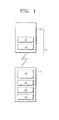
- FIG. 1 is a diagram schematically illustrating a terminal system according an embodiment of the present invention
- FIG.2 is a diagram illustrating an example in which the terminal system of FIG. 1 is used;
- FIG. 3 illustrates a bent second terminal of FIG. 1 ;
- FIG. 4 illustrates a flat second terminal of FIG. 1 ;
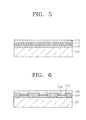
- FIG. 5 is a cross-sectional view illustrating an example of a display unit of the second terminal
- FIG. 6 is a cross-sectional view illustrating another example of the display unit of the second terminal.
- FIG. 7 is a cross-sectional view illustrating another example of the display unit of the second terminal.
- FIG. 8 is a cross-sectional view illustrating another example of the display unit of the second terminal.
- FIG. 1 is a diagram schematically illustrating a terminal system 30 according to an embodiment of the present invention.
- the terminal system 30 includes a first terminal 10 and a second terminal 20.
- the first terminal 10 and the second terminal 20 are separated and spaced apart from each other.
- the first and second terminals are coupled (e.g., connected) to each other over a wireless local area network such as a Bluetooth (Bluetooth is a registered trademark of Bluetooth Sig, Inc., a Delaware Corporation) network. Further details are described below.
- Bluetooth Bluetooth is a registered trademark of Bluetooth Sig, Inc., a Delaware Corporation
- the first terminal 10 includes a first control unit 11 and a first communication unit 12. Although in FIG. 1 , the first control unit 11 and the first communication unit 12 are separated from each other, the present invention is not limited thereto. That is, the first control unit 11 and the first communication unit 12 may be integrated. As illustrated in FIG. 2 , the first terminal 10 may be a mobile phone, in particular, a smartphone. The first control unit 11 controls the first communication unit 12 so that the first terminal 10 and the second terminal 20 communicate with each other, further details of which are included below.
- the second terminal 20 includes a second control unit 21, a second communication unit 22, a transformation sensing unit 23, and a display unit 24.
- the second terminal 20 is flexible so that it may be bent and/or folded according to a user's convenience. As a detailed example, as illustrated in FIG. 2 , the second terminal 20 may be worn on a user's wrist in the form of a band.
- the present invention is not limited thereto, and the second terminal 20 having flexibility may be worn on any portion of the body, be attached to clothing, and may also be fixed to a portion of a bicycle or other device. That is, the second terminal 20 is formed to be fixed to a portion of the body, a portion of clothing, or a portion of a bicycle or other sports equipment so that a user may easily check the display unit 24 while riding a bicycle as illustrated in FIG. 2 or doing other types of exercise.
- the transformation sensing unit 23 senses the extent of transformation (e.g., the extent of bending and/or folding) when the second terminal 20 is transformed by bending or folding thereof while, for example, wearing the second terminal 20 on a portion of the body, for example, the wrist.
- the transformation sensing unit 23 may include various sensors, and for example, a piezoelectric sensor.
- the second control unit 21 receives information about the extent of transformation of the second terminal 20, which the transformation sensing unit 23 has sensed.
- An operation of the second communication unit 22 is controlled by the second control unit 21. That is, when the second control unit 21 determines that the second terminal 20 has been transformed by a set or predetermined amount (e.g., a reference amount or first amount) through information received from the transformation sensing unit 23, the second control unit 21 allows the second communication unit 22 and the first communication unit 12 to be coupled (e.g., connected) to each other over a local area wireless communication network and to transmit and receive information between them.
- a set or predetermined amount e.g., a reference amount or first amount
- the second control unit 21 activates the second communication unit 22 to enable local area wireless communication, for example, Bluetooth communication, as a result of information received from the transformation sensing unit 23.
- the second control unit 21 transmits a signal to the first control unit 11, and the first control unit 11 activates the first communication unit 12 to enable local area wireless communication, for example, Bluetooth communication, as a result of the signal received from the second control unit 21.
- the activated first communication unit 12 and the activated second communication unit 22 may be coupled to each other by the local area wireless communication network and may exchange information with each other. In particular, information may be transmitted from the first terminal 10 to the second terminal 20.
- the second control unit 21 activates the second communication unit 22 to enable local area wireless communication, for example, Bluetooth communication, as a result of information received from the transformation sensing unit 23.
- the second communication unit 22 then transmits a signal to the first control unit 11 by using the local area wireless communication, and the first control unit 11 activates the first communication unit 12 to enable local area wireless communication, for example, Bluetooth communication, as a result of the signal received from the second communication unit 22.
- the first control unit 11 controls the first communication unit 12 to transmit predetermined or set information, selected in advance, from the first communication unit 12 to the second communication unit 22.
- the first control unit 11 also activates the first communication unit 12 to enable local area wireless communication when receiving a signal from the second control unit 21 or the second communication unit 22 as described above.
- information that is transmitted from the first communication unit 12 to the second communication unit 22 may be text messages received by the first terminal 10, and may be the current covered distance or travelling time of a user, which has been measured by the first terminal 10.
- the first terminal 10 when it is a smartphone, it may include various applications for checking a body condition of a user.
- the first terminal 10 may obtain information of a user through the various applications, and may transmit the information from the first communication unit 12 to the second communication unit 22.
- the display unit 24 displays information of the first terminal 10 received through communication between the first communication unit 12 and the second communication unit 22. That is, the display unit 24 displays, for example, text messages received by the first terminal 10 or various information of a user, which has been measured by the first terminal 10.
- the second control unit 21 controls the display unit 24 so that the display unit 24 may appropriately display information which the second communication unit 22 has received from the first communication unit 12.
- the display unit 24 may display information generated by the second terminal 20 according to information sensed by the transformation sensing unit 23. That is, when the extent of transformation of the second terminal 20, which the transformation sensing unit 23 has sensed, is smaller than a predetermined or set amount (e.g., a reference amount), brief information generated by the second terminal 20, instead of information of the first terminal 10, may be displayed. Further details are described below.
- a predetermined or set amount e.g., a reference amount
- FIG. 3 illustrates a bent second terminal 20.
- FIG. 3 illustrates a form of the second terminal 20 when a user is wearing the second terminal 20 on the wrist as illustrated in FIG. 2 .
- the transformation sensing unit 23 of the second terminal 20 senses a bend of the second terminal 20 and transmits information about a sensed result to the second control unit 21.
- the second control unit 21 determines that the second terminal 20 has been bent by a predetermined or set amount (e.g., a reference amount), through the information sensed by the transformation sensing unit 23, and activates the second communication unit 22 to enable a local area wireless connection (e.g., Bluetooth communication).
- a predetermined or set amount e.g., a reference amount
- the second control unit 21 transmits a signal to the first control unit 11 according to the information about the sensed result.
- the second communication unit 22 activated by the second control unit 21 may transmit the signal to the first control unit 11 (instead of the second control unit 21).
- the first control unit 11 that has received the signal from the second control unit 21 or the second communication unit 22 activates the first communication unit 12 to enable local area wireless communication between the first communication unit 12 and the second communication unit 22.
- the first terminal 10 may be a mobile phone such as a smartphone, and the first terminal 10 may transmit a received text message to the second terminal 20.
- the first terminal 10 may measure a covered distance and/or a travelling time at a specific point in time and may transmit the measured distance and time to the second terminal 20.
- the first terminal 10 may measure the covered distance and the travelling time by including an application for providing a GPS function.
- the second control unit 21 that controls the second communication unit 22 and the display unit 24 makes the display unit 24 display the information of the first terminal 10 in an appropriate form. That is, as a detailed example, as illustrated in FIG. 3 , the text message received by the first terminal 10 is displayed on an upper side of the display unit 24, and the covered distance and travelling time measured by the first terminal 10 is displayed on a lower side of the display unit 24.
- the first terminal 10 may acquire various information and may process the acquired information. That is, the first terminal 10 that is a smartphone may acquire various information, for example, call waiting information, traffic volume around the current position of a user, or the like by using software embedded therein, an application downloaded by the user, and/or a separately installed chip. The first terminal 10 may then display some or all of the various information on the display unit 24 of the second terminal 20.
- the second terminal 20 may be lighter, smaller, and more compact. Thus, it may be more convenient and comfortable to wear the second terminal 20 on a portion of the body.
- FIG. 4 illustrates a flat second terminal 20.
- the transformation sensing unit 23 senses the state of the second terminal 20 and transmits information about the sensed state to the second control unit 21, and the second control unit 21 disables a local area wireless communication function of the second communication unit 22.
- the second control unit 21 of the second terminal 20 may generate predetermined or set information, e.g., information such as the current time, that is, e.g., received from a time information chip (not shown) separately disposed in the second terminal 20, and makes the display unit 24 display the information.
- predetermined or set information e.g., information such as the current time, that is, e.g., received from a time information chip (not shown) separately disposed in the second terminal 20, and makes the display unit 24 display the information.
- the second terminal 20 directly displays information thereon (i.e., time), independent of the information of the first terminal 10.
- the second control unit 21 since a local area wireless communication function of the second communication unit 22 of the second terminal 20 is discontinued, the second control unit 21 does not need to transmit a separate signal to the first control unit 11 of the first terminal 10. However, as a selective example, the second control unit 21 may transmit a separate signal to the first control unit 11, and the first control unit 11 may interrupt the local area wireless communication function of the first communication unit 12.
- the first terminal 10 When performing an activity, such as cycling or running, the first terminal 10, such as a smartphone, may be stored in a knapsack (or other bag or purse), and thus, a user may not easily check information of the first terminal 10.
- a user In the terminal system 30 according to the current embodiment, a user may also check desired information through the second terminal 20.
- the second terminal 20 is formed to have a form of a flexible band that is easily worn on a portion of the body of a user, for example, the wrist, thereby improving user convenience.
- the second terminal 20 communicates with the first terminal 10 when the second terminal 20 has been transformed.
- the second terminal is worn on the wrist of a user and thus the user may be able to substantially check only the second terminal 20.
- a communication function between the first terminal 10 and the second terminal 20 is deactivated when the second terminal 20 has not been transformed (e.g., is flat), that is, when the user is not wearing the second terminal 20, and thus is not checking the second terminal 20.
- the terminal system 30 may be optimized.
- the efficiency of electrical power use of the first and second terminals 10 and 20 may be improved through an efficient operation of the first and second terminals 10 and 20.
- the second terminal 20 does not generate complicated information but generates only simple information, it is relatively easy to make the second terminal 20 smaller and more compact, and thus, it is possible to increase the ways to wear the second terminal 20 and to improve design flexibility of the second terminal 20.
- the display unit 24 may also have a certain flexibility.
- the second terminal 20 may include various forms of display units in which information is displayed (and be visually recognized by a user). A detailed example of the display unit 24 is described below.
- FIG. 5 is a cross-sectional view illustrating an example of the display unit 24 of the second terminal 20.
- the display unit 24 includes a first electrode 110, an intermediate layer 114, and a second electrode 115 on a substrate 201.
- the substrate 201 is formed of a flexible material.
- the substrate 201 may be formed of a transparent plastic material or any other suitable flexible substrate material.
- the first electrode 110 is formed on the substrate 201.
- the first electrode 110 may include a material such as indium tin oxide (ITO), indium zinc oxide (IZO), ZnO, or In 2 O 3 .
- the first electrode 110 may further include a reflection film formed of Ag, Mg, Al, Pt, Pd, Au, Ni, Nd, Ir, Cr, Li, Yb, and/or Ca.
- a buffer layer (not shown) may be formed between the substrate 201 and the first electrode 110.
- the buffer layer prevents impurities (e.g., undesirable elements) from entering into the substrate 201 and provides a flat surface on the substrate 201.
- the buffer layer may be formed by using one of various materials capable of performing the aforementioned functions.
- the buffer layer may include inorganic materials such as silicon oxide, silicon nitride, silicon oxynitride, aluminum oxide, aluminum nitride, titanium oxide, titanium nitride, and/or the like; organic materials such as polyimides, polyesters, compounds containing an acryl group, and/or the like; or may be a stacked structure including multiple layers, each layer optionally including one or more of the aforementioned materials.
- inorganic materials such as silicon oxide, silicon nitride, silicon oxynitride, aluminum oxide, aluminum nitride, titanium oxide, titanium nitride, and/or the like
- organic materials such as polyimides, polyesters, compounds containing an acryl group, and/or the like
- each layer optionally including one or more of the aforementioned materials.
- the intermediate layer 114 is formed on the first electrode 110.
- the intermediate layer 114 includes an organic emission layer to form visible light.
- the intermediate layer 114 may be formed as a low-molecular weight organic layer or a high-molecular weight organic layer.
- the intermediate layer 114 may include a hole injection layer (HIL), a hole transport layer (HTL), an organic emission layer, an electron transport layer (ETL), an electron injection layer (EIL), and the like.
- the HIL may be formed of a phthalocyanine compound such as copper phthalocyanine, a star-burst type amine such as tris(4-carbazoyl-9-ylphenyl)amine (TCTA), 4,4',4"-Tris(N-3-methylphenyl-N-phenylamino)triphenylamine (m-MTDATA), and/or 1,3,5-tris[4-(3-metylphenylphenylamino)phenyl]benzene (m-MTDAPB), and/or the like.
- TCTA tris(4-carbazoyl-9-ylphenyl)amine
- m-MTDATA 4,4',4"-Tris(N-3-methylphenyl-N-phenylamino)triphenylamine
- m-MTDAPB 1,3,5-tris[4-(3-metylphenylphenylamino)phenyl]benzene
- the HTL may be formed of N,N'-bis(3-methylphenyl)-N,N'-diphenyl-[1,1-biphenyl]-4,4'-diamine (TPD), N,N'-di(naphthalene-1-yl)-N,N'-diphenyl benzidine ( ⁇ -NPD), and/or the like.
- TPD N,N'-bis(3-methylphenyl)-N,N'-diphenyl-[1,1-biphenyl]-4,4'-diamine
- ⁇ -NPD N,N'-di(naphthalene-1-yl)-N,N'-diphenyl benzidine
- the EIL may be formed of a material such as LiF, NaCl, CsF, Li 2 O, BaO, lithium quinolate (Liq), and/or the like.
- the ETL may be formed of Alq 3 and/or the like.
- the organic emission layer may include a host material and a dopant material.
- the host material of the organic emission layer may be tris(8-hydroxy-quinolinato)aluminum (Alq 3 ), 9,10-di(naphth-2-yl)anthracene (ADN), 3-tert-butyl-9,10-di(naphth-2-yl)anthracene (TBADN), 4,4'-bis(2,2-diphenyl-ethene-1-yl)-4,4'-dimethylphenyl (DPVBi), 4,4'-bis(2,2-diphenyl-ethene-1-yl)-4,4'-dimethylphenyl (p-DMDPVBi), tert(9,9-diarylfluorene)s (TDAF), 2-(9,9'-spirobifluorene-2-yl)-9,9'-spirobifluorene(BSDF), 2,7-bis(9,9'-spirobifluorene-2-yl)-9,9'-
- Examples of the dopant material of the organic emission layer include 4,4'-bis[4-(di-p-tolylamino)styryl]biphenyl (DPAVBi), 9,10-di(naphth-2-yl)anthracene (ADN), 3-tert-butyl-9,1 0-di(naphth-2-yl)anthracene (TBADN), and/or the like.
- DPAVBi 4,4'-bis[4-(di-p-tolylamino)styryl]biphenyl
- ADN 9,10-di(naphth-2-yl)anthracene
- TAADN 3-tert-butyl-9,1 0-di(naphth-2-yl)anthracene
- the second electrode 115 is formed on the intermediate layer 114.
- the second electrode 115 may be formed of a metal such as Ag, Mg, Al, Pt, Pd, Au, Ni, Nd, Ir, Cr, Li, and/or Ca.
- FIG. 6 is a cross-sectional view illustrating another example of the display unit 24 of the second terminal 20.
- the display unit 24 includes a first electrode 210, a pixel-defining layer 219, an intermediate layer 214, and a second electrode 215 on a substrate 201.
- a configuration of each element will be described in detail. For convenience of description, mainly the differences from the above example will now be described.
- the first electrode 210 is formed on the substrate 201.
- the pixel-defining layer 219 is formed on the first electrode 210 by using an insulation material.
- the pixel-defining layer 219 has an opening to expose an upper surface of the first electrode 210.
- the intermediate layer 214 is formed on the exposed upper surface of the first electrode 210.
- the intermediate layer 214 includes an organic emission layer to emit visible light.
- the second electrode 215 is formed on the intermediate layer 214.
- FIG. 7 is a cross-sectional view illustrating another example of the display unit 24 of the second terminal 20.
- the display unit 24 includes a thin film transistor TFT formed on a substrate 301.
- the TFT includes an active layer 303, a gate electrode 305, a source electrode 307, and a drain electrode 308.
- a buffer layer 302 may optionally be formed on the substrate 301.
- the active layer 303 having a predetermined or set pattern (e.g., a first pattern) is formed on the buffer layer 302.
- the active layer 303 may be formed of an inorganic semiconductor, such as amorphous silicon or polysilicon, or an organic semiconductor.
- the active layer 303 includes a source area, a drain area, and a channel area.
- the source and drain areas of the active layer 303 may be formed by doping the active layer 303 with Group III and/or Group V impurities after the active layer 303 is formed of amorphous silicon or polysilicon.
- a gate insulation film 304 is formed on the active layer 303, and the gate electrode 305 is formed on a predetermined or set area (e.g., a first area) of the gate insulation film 304.
- the gate insulation film 304 insulates the gate electrode 305 from the active layer 303 and may be formed of an organic material or an inorganic material, such as SiNx and/or SiO 2 .
- the gate electrode 305 may include Au, Ag, Cu, Ni, Pt, Pd, Al, Mo, and/or an alloy, and may be an Al:Nd alloy or a Mo:W alloy.
- the material for forming the gate electrode 305 is not limited thereto, and various other materials may also be used to form the gate electrode 305 in consideration of adhesion with respect to an adjacent layer, planarization, electric resistance, and/or processability.
- An interlayer dielectric 317 is formed on the gate electrode 305.
- the interlayer dielectric 317 and the gate insulation film 304 are formed to expose the source and drain areas of the active layer 303.
- the source electrode 307 and the drain electrode 308 are formed to contact respective exposed source and drain areas of the active layer 303.
- the source electrode 307 and the drain electrode 308 may each be formed of any one of various conductive materials and may have a single-layer or multi-layer structure.
- a passivation layer 318 is formed on the TFT.
- the passivation layer 318 is formed on the source electrode 307 and the drain electrode 308.
- the passivation layer 318 is formed to expose a predetermined or set area (e.g., a first area) of the drain electrode 308 by not covering the whole drain electrode 308.
- a first electrode 310 is formed to be coupled (e.g. connected) to the exposed portion of the drain electrode 308.
- a pixel-defining film 319 is formed of an insulating material on the first electrode 310.
- the pixel-defining film 319 is formed to expose a predetermined or set area (e.g., a first area) of the first electrode 310.
- An intermediate layer 314 is formed to be coupled (e.g. connected) to the exposed portion of the first electrode 310.
- a second electrode 315 is formed to be coupled (e.g. connected) to the intermediate layer 314.
- a sealing element (not shown) may be disposed on the second electrode 315.
- the sealing element may be formed to protect the intermediate layer 314 and other layers from external humidity and/or oxygen.
- the sealing element may include plastic or may have a multi-layer structure of alternating organic material and inorganic material.
- FIG. 8 is a cross-sectional view illustrating another example of the display unit 24 of the second terminal 20.
- the display unit 24 includes a capacitor 418 and a thin film transistor TFT formed on a substrate 401.
- the TFT includes an active layer 403, a gate electrode 405, a source electrode 407, and a drain electrode 408.
- a buffer layer 402 is formed on the substrate 401.
- the active layer 403 having a predetermined or set area e.g., a first area
- a first capacitor electrode 411 is formed on the buffer layer 402.
- the first capacitor electrode 411 may be formed of the same material as the active layer 403.
- a gate insulating layer 404 is formed on the buffer layer 402 to cover the active layer 403 and the first capacitor electrode 411.
- the gate electrode 405, a first electrode 410, and a second capacitor electrode 413 are formed on the gate insulating layer 404.
- the gate electrode 405 includes a first conductive layer 405a and a second conductive layer 405b.
- the first electrode 410 may be formed of the same material as the first conductive layer 405a.
- a conductive portion 410a is disposed on a predetermined upper portion of the first electrode 410.
- the conductive portion 410a may be formed of the same material as the second conductive layer 405b.
- the second capacitor electrode 413 includes a first layer 413a and a second layer 413b.
- the first layer 413a may be formed of the same material as the first conductive layer 405a
- the second layer 413b may be formed of the same material as the second conductive layer 405b.
- the second layer 413b is formed on the first layer 413a to be smaller than the first layer 413a.
- the second capacitor electrode 413 overlaps with the first capacitor electrode 411, and is smaller than the first capacitor electrode 411.
- An interlayer dielectric 417 is formed on the first electrode 410, the gate electrode 405, and the second capacitor electrode 413.
- the source electrode 407 and the drain electrode 408 are formed on the interlayer dielectric 417 and are coupled (e.g. connected) to the active layer 403.
- one of the source electrode 407 and the drain electrode 408 is electrically coupled (e.g. connected) to the first electrode 410.
- FIG. 8 shows that the drain electrode 408 is electrically coupled to the first electrode 410.
- the drain electrode 408 contacts the active layer 403 and the conductive portion 410a.
- a pixel-defining layer 419 is formed on the interlayer dielectric 417 to cover the source electrode 407, the drain electrode 408, and the capacitor 418.
- the pixel-defining layer 419 includes an opening 419a that corresponds to an upper surface of the first electrode 410, and an intermediate layer 414 is formed on the first electrode 410 that is exposed through the opening 419a of the pixel-defining layer 419.
- a second electrode 415 is formed on the intermediate layer 414.
- a sealing element (not shown) may be disposed on the second electrode 415.
- the sealing element may be formed to prevent damage to the first electrode 410, the intermediate layer 414, or the second electrode 415 by external foreign bodies or shock.
- the sealing element may be formed by using glass, a thin metal film, or the like, or it may have a stacked structure, each layer formed of an organic material and/or an inorganic material.
- the display unit 24 of the second terminal 20 may be a liquid crystal device or any other suitable display device.
Landscapes
- Engineering & Computer Science (AREA)
- Theoretical Computer Science (AREA)
- General Engineering & Computer Science (AREA)
- General Physics & Mathematics (AREA)
- Physics & Mathematics (AREA)
- Human Computer Interaction (AREA)
- Computer Hardware Design (AREA)
- Signal Processing (AREA)
- Computer Networks & Wireless Communication (AREA)
- Telephone Function (AREA)
- Devices For Indicating Variable Information By Combining Individual Elements (AREA)
- Electroluminescent Light Sources (AREA)
- Telephone Set Structure (AREA)
Abstract
Description
- The present invention relates to a terminal system and a flexible terminal.
- Terminals have a wide range of uses. Among them, mobile phones perform various functions as well as a conventional telephonic function, and recently, the uses thereof are expanding. In particular, a smartphone performs various functions such as reproducing and recording multimedia content, execution of applications, and the like by installing a system similar to a computer operating system therein.
- In addition, if necessary or desired, such a smartphone may additionally include a function desired by a user that is enabled through installation of a separate component, such as a functional chip, other than installation of applications.
- Often, a user carries a mobile phone, such as a smartphone, during an activity such as cycling or running. However, when running or jogging, it is difficult for the user to check information on the mobile phone. Thus, recent terminals, such as mobile phones, are limited in improving user convenience.
- Aspects of embodiments of the present invention are directed to a terminal system that improves user convenience. That is, aspects of embodiments of the invention are directed to a flexible terminal that improves user convenience.
- According to an aspect of the present invention, a flexible terminal having a local area wireless communication function is adapted to be bent and/or folded, to sense an amount of deflection of the flexible terminal, and to display different information according to the amount of deflection of the flexible terminal.
- According to another aspect of the present invention, a mobile terminal adapted to exchange information with a flexible terminal comprises a first communication unit adapted to transmit and/or receive information through a local area wireless communication network, and a first control unit adapted to control the first communication unit.
- According to a further aspect of the present invention, a terminal system includes a first terminal and a second terminal that are coupled to each other through a local area wireless communication network, and the second terminal senses an amount of transformation of the second terminal and displays different information according to the amount of transformation of the second terminal.
- The second terminal may display information generated by the first terminal or information generated by the second terminal according to the amount of transformation of the second terminal. When the second terminal is transformed by at least a reference amount, the second terminal may be coupled to the first terminal through the local area wireless communication network and may display information received from the first terminal. When the amount of transformation of the second terminal is less than a reference amount, the second terminal may display information generated by the second terminal.
- When the amount of transformation of the second terminal is less than a reference amount, a local area wireless communication function between the second terminal and the first terminal may be discontinued.
- According to some embodiments, a terminal system includes a first terminal including a first communication unit that transmits and/or receives information through a local area wireless communication network and a first control unit that controls the first communication unit. The terminal system also includes a second terminal including a second communication unit that communicates with the first communication unit, a second control unit that controls the second communication unit, a display unit that is controlled by the second control unit and displays information, and a transformation sensing unit. The transformation sensing unit senses the amount of transformation of the second terminal, and the second control unit receives information about the amount of transformation of the second terminal from the transformation sensing unit and controls the display unit according to the received information.
- The second terminal may display information generated by the first terminal or information generated by the second terminal according to the amount of transformation of the second terminal, the amount of transformation of the second terminal being sensed by the transformation sensing unit.
- The local area wireless communication between the first communication unit and the second communication unit may be started according to the amount of transformation of the second terminal, the amount of transformation of the second terminal being sensed by the transformation sensing unit.
- Information that is displayed on the display unit when the first communication unit and the second communication unit are coupled over the local area wireless communication network may be different from that when the first communication unit and the second communication unit are not coupled over the local area wireless communication network.
- Information received from the first terminal may be displayed on the display unit when the first communication unit and the second communication unit are coupled over the local area wireless communication network, and information generated by the second terminal may be displayed on the display unit when the first communication unit and the second communication are not coupled over the local area wireless communication network.
- The second communication unit may be activated to enable local area wireless communication when the amount of transformation of the second terminal is equal to or greater than a reference amount, and the second communication unit may be deactivated to disable the local area wireless communication when the amount of transformation of the second terminal is less than the reference amount, the amount of transformation of the second terminal being sensed by the transformation sensing unit.
- The first control unit may activate the first communication unit to enable local area wireless communication when the amount of transformation of the second terminal is equal to or greater than a reference amount, the amount of transformation of the second terminal being sensed by the transformation sensing unit.
- When the amount of transformation of the second terminal is equal to or greater than a reference amount, the second control unit may transmit information about the amount of transformation of the second terminal to the first control unit, and the first control unit may activate the first communication unit to enable local area wireless communication, the amount of transformation of the second terminal being sensed by the transformation sensing unit.
- When the amount of transformation of the second terminal is equal to or greater than a reference amount, the second communication unit may transmit information about the extent of transformation of the second terminal to the first control unit, and the first control unit may activate the first communication unit to enable local area wireless communication, the amount of transformation of the second terminal being sensed by the transformation sensing unit
- The local area wireless communication network may be a Bluetooth network.
- The first terminal may be a mobile phone.
- The second terminal may be flexible and adapted to be bent or folded.
- The second terminal may be a band configurable to be worn on a portion of a user's body.
- The first control unit and the first communication unit may be integrated. The second control unit and the second communication unit may be integrated.
- The display unit may include a first electrode, a second electrode, and an intermediate layer between the first electrode and the second electrode, the intermediate layer including an organic emission layer. The display unit may further include a thin film transistor that is electrically coupled to the first electrode, the thin film transistor including an active layer, a gate electrode, a source electrode, and a drain electrode. The first electrode may be on the same layer as the gate electrode.
- The display unit may include a liquid crystal layer.
- In some embodiments, a flexible terminal has a local area wireless communication function, and the flexible terminal may sense the amount of transformation of the flexible terminal and may display different information according to the amount of transformation of the flexible terminal.
- The local area wireless communication function of the flexible terminal may be activated when the flexible terminal is transformed by at least a reference amount, and the local area wireless communication function of the flexible terminal may be deactivated when the flexible terminal is transformed by less than the reference amount.
- When the flexible terminal is transformed by at least a reference amount, the local area wireless communication function of the flexible terminal may be activated, and the flexible terminal may be coupled to an external terminal through a local area wireless communication network and the flexible terminal may display information received from the external terminal.
- When the flexible terminal is transformed by less than a reference amount, the flexible terminal may display information generated by the flexible terminal.
- A terminal system and flexible terminal according to embodiments of the present invention may improve user convenience.
- The above and other features and aspects of the present invention will become more apparent by describing in detail exemplary embodiments thereof with reference to the attached drawings in which:
-
FIG. 1 is a diagram schematically illustrating a terminal system according an embodiment of the present invention; -
FIG.2 is a diagram illustrating an example in which the terminal system ofFIG. 1 is used; -
FIG. 3 illustrates a bent second terminal ofFIG. 1 ; -
FIG. 4 illustrates a flat second terminal ofFIG. 1 ; -
FIG. 5 is a cross-sectional view illustrating an example of a display unit of the second terminal; -
FIG. 6 is a cross-sectional view illustrating another example of the display unit of the second terminal; -
FIG. 7 is a cross-sectional view illustrating another example of the display unit of the second terminal; and -
FIG. 8 is a cross-sectional view illustrating another example of the display unit of the second terminal. - Hereinafter, the present invention will be described in detail by explaining exemplary embodiments of the invention with reference to the attached drawings.
-
FIG. 1 is a diagram schematically illustrating aterminal system 30 according to an embodiment of the present invention. Referring toFIG. 1 , theterminal system 30 includes afirst terminal 10 and asecond terminal 20. Thefirst terminal 10 and thesecond terminal 20 are separated and spaced apart from each other. In a specific condition, the first and second terminals are coupled (e.g., connected) to each other over a wireless local area network such as a Bluetooth (Bluetooth is a registered trademark of Bluetooth Sig, Inc., a Delaware Corporation) network. Further details are described below. - The
first terminal 10 includes afirst control unit 11 and afirst communication unit 12. Although inFIG. 1 , thefirst control unit 11 and thefirst communication unit 12 are separated from each other, the present invention is not limited thereto. That is, thefirst control unit 11 and thefirst communication unit 12 may be integrated. As illustrated inFIG. 2 , thefirst terminal 10 may be a mobile phone, in particular, a smartphone. Thefirst control unit 11 controls thefirst communication unit 12 so that thefirst terminal 10 and thesecond terminal 20 communicate with each other, further details of which are included below. - The
second terminal 20 includes a second control unit 21, a second communication unit 22, atransformation sensing unit 23, and adisplay unit 24. - The
second terminal 20 is flexible so that it may be bent and/or folded according to a user's convenience. As a detailed example, as illustrated inFIG. 2 , thesecond terminal 20 may be worn on a user's wrist in the form of a band. The present invention is not limited thereto, and thesecond terminal 20 having flexibility may be worn on any portion of the body, be attached to clothing, and may also be fixed to a portion of a bicycle or other device. That is, thesecond terminal 20 is formed to be fixed to a portion of the body, a portion of clothing, or a portion of a bicycle or other sports equipment so that a user may easily check thedisplay unit 24 while riding a bicycle as illustrated inFIG. 2 or doing other types of exercise. - The
transformation sensing unit 23 senses the extent of transformation (e.g., the extent of bending and/or folding) when thesecond terminal 20 is transformed by bending or folding thereof while, for example, wearing thesecond terminal 20 on a portion of the body, for example, the wrist. For this, thetransformation sensing unit 23 may include various sensors, and for example, a piezoelectric sensor. - The second control unit 21 receives information about the extent of transformation of the
second terminal 20, which thetransformation sensing unit 23 has sensed. - An operation of the second communication unit 22 is controlled by the second control unit 21. That is, when the second control unit 21 determines that the
second terminal 20 has been transformed by a set or predetermined amount (e.g., a reference amount or first amount) through information received from thetransformation sensing unit 23, the second control unit 21 allows the second communication unit 22 and thefirst communication unit 12 to be coupled (e.g., connected) to each other over a local area wireless communication network and to transmit and receive information between them. - As a detailed example, the second control unit 21 activates the second communication unit 22 to enable local area wireless communication, for example, Bluetooth communication, as a result of information received from the
transformation sensing unit 23. In addition, the second control unit 21 transmits a signal to thefirst control unit 11, and thefirst control unit 11 activates thefirst communication unit 12 to enable local area wireless communication, for example, Bluetooth communication, as a result of the signal received from the second control unit 21. - The activated
first communication unit 12 and the activated second communication unit 22 may be coupled to each other by the local area wireless communication network and may exchange information with each other. In particular, information may be transmitted from thefirst terminal 10 to thesecond terminal 20. - As another example, the second control unit 21 activates the second communication unit 22 to enable local area wireless communication, for example, Bluetooth communication, as a result of information received from the
transformation sensing unit 23. The second communication unit 22 then transmits a signal to thefirst control unit 11 by using the local area wireless communication, and thefirst control unit 11 activates thefirst communication unit 12 to enable local area wireless communication, for example, Bluetooth communication, as a result of the signal received from the second communication unit 22. - The
first control unit 11 controls thefirst communication unit 12 to transmit predetermined or set information, selected in advance, from thefirst communication unit 12 to the second communication unit 22. Thefirst control unit 11 also activates thefirst communication unit 12 to enable local area wireless communication when receiving a signal from the second control unit 21 or the second communication unit 22 as described above. As a detailed example, information that is transmitted from thefirst communication unit 12 to the second communication unit 22 may be text messages received by thefirst terminal 10, and may be the current covered distance or travelling time of a user, which has been measured by thefirst terminal 10. - That is, when the
first terminal 10 is a smartphone, it may include various applications for checking a body condition of a user. Thefirst terminal 10 may obtain information of a user through the various applications, and may transmit the information from thefirst communication unit 12 to the second communication unit 22. - The
display unit 24 displays information of thefirst terminal 10 received through communication between thefirst communication unit 12 and the second communication unit 22. That is, thedisplay unit 24 displays, for example, text messages received by thefirst terminal 10 or various information of a user, which has been measured by thefirst terminal 10. In this case, the second control unit 21 controls thedisplay unit 24 so that thedisplay unit 24 may appropriately display information which the second communication unit 22 has received from thefirst communication unit 12. - The
display unit 24 may display information generated by thesecond terminal 20 according to information sensed by thetransformation sensing unit 23. That is, when the extent of transformation of thesecond terminal 20, which thetransformation sensing unit 23 has sensed, is smaller than a predetermined or set amount (e.g., a reference amount), brief information generated by thesecond terminal 20, instead of information of thefirst terminal 10, may be displayed. Further details are described below. - A detailed operation of the
terminal system 30 is explained below with reference toFIGS. 3 and 4 . -
FIG. 3 illustrates a bentsecond terminal 20. In detail,FIG. 3 illustrates a form of thesecond terminal 20 when a user is wearing thesecond terminal 20 on the wrist as illustrated inFIG. 2 . - When the
second terminal 20 is bent as inFIG. 3 , for example, when a user wears thesecond terminal 20 on the wrist, thetransformation sensing unit 23 of thesecond terminal 20 senses a bend of thesecond terminal 20 and transmits information about a sensed result to the second control unit 21. The second control unit 21 determines that thesecond terminal 20 has been bent by a predetermined or set amount (e.g., a reference amount), through the information sensed by thetransformation sensing unit 23, and activates the second communication unit 22 to enable a local area wireless connection (e.g., Bluetooth communication). - Then, the second control unit 21 transmits a signal to the
first control unit 11 according to the information about the sensed result. As described above, the second communication unit 22 activated by the second control unit 21 may transmit the signal to the first control unit 11 (instead of the second control unit 21). - The
first control unit 11 that has received the signal from the second control unit 21 or the second communication unit 22 activates thefirst communication unit 12 to enable local area wireless communication between thefirst communication unit 12 and the second communication unit 22. Through the local area wireless communication network, information of thefirst terminal 10 is transmitted to thesecond terminal 20. As a detailed example, thefirst terminal 10 may be a mobile phone such as a smartphone, and thefirst terminal 10 may transmit a received text message to thesecond terminal 20. In addition, when a user moves, for example, while riding a bicycle as illustrated inFIG. 2 , thefirst terminal 10 may measure a covered distance and/or a travelling time at a specific point in time and may transmit the measured distance and time to thesecond terminal 20. As described above, thefirst terminal 10 may measure the covered distance and the travelling time by including an application for providing a GPS function. - When the second communication unit 22 receives the information of the
first terminal 10 through the local area wireless communication network, the second control unit 21 that controls the second communication unit 22 and thedisplay unit 24 makes thedisplay unit 24 display the information of thefirst terminal 10 in an appropriate form. That is, as a detailed example, as illustrated inFIG. 3 , the text message received by thefirst terminal 10 is displayed on an upper side of thedisplay unit 24, and the covered distance and travelling time measured by thefirst terminal 10 is displayed on a lower side of thedisplay unit 24. - The
first terminal 10 may acquire various information and may process the acquired information. That is, thefirst terminal 10 that is a smartphone may acquire various information, for example, call waiting information, traffic volume around the current position of a user, or the like by using software embedded therein, an application downloaded by the user, and/or a separately installed chip. Thefirst terminal 10 may then display some or all of the various information on thedisplay unit 24 of thesecond terminal 20. - In the current embodiment, because the
second terminal 20 receives various information acquired by thefirst terminal 10 and displays some or all of the received information on thedisplay unit 24 without a separate information generation component, thesecond terminal 20 may be lighter, smaller, and more compact. Thus, it may be more convenient and comfortable to wear thesecond terminal 20 on a portion of the body. -
FIG. 4 illustrates a flatsecond terminal 20. As illustrated inFIG. 4 , when thesecond terminal 20 is flat, that is, thesecond terminal 20 is not worn on the wrist of a user, thetransformation sensing unit 23 senses the state of thesecond terminal 20 and transmits information about the sensed state to the second control unit 21, and the second control unit 21 disables a local area wireless communication function of the second communication unit 22. - In addition, in its flat (or untransformed) state, the second control unit 21 of the
second terminal 20 may generate predetermined or set information, e.g., information such as the current time, that is, e.g., received from a time information chip (not shown) separately disposed in thesecond terminal 20, and makes thedisplay unit 24 display the information. - That is, as illustrated in
FIG. 4 , thesecond terminal 20 directly displays information thereon (i.e., time), independent of the information of thefirst terminal 10. - In this case, since a local area wireless communication function of the second communication unit 22 of the
second terminal 20 is discontinued, the second control unit 21 does not need to transmit a separate signal to thefirst control unit 11 of thefirst terminal 10. However, as a selective example, the second control unit 21 may transmit a separate signal to thefirst control unit 11, and thefirst control unit 11 may interrupt the local area wireless communication function of thefirst communication unit 12. - When performing an activity, such as cycling or running, the
first terminal 10, such as a smartphone, may be stored in a knapsack (or other bag or purse), and thus, a user may not easily check information of thefirst terminal 10. In theterminal system 30 according to the current embodiment, a user may also check desired information through thesecond terminal 20. - Also, the
second terminal 20 is formed to have a form of a flexible band that is easily worn on a portion of the body of a user, for example, the wrist, thereby improving user convenience. - In particular, as transformation of the
second terminal 20 is sensed, thesecond terminal 20 communicates with thefirst terminal 10 when thesecond terminal 20 has been transformed. For instance, the second terminal is worn on the wrist of a user and thus the user may be able to substantially check only thesecond terminal 20. A communication function between thefirst terminal 10 and thesecond terminal 20 is deactivated when thesecond terminal 20 has not been transformed (e.g., is flat), that is, when the user is not wearing thesecond terminal 20, and thus is not checking thesecond terminal 20. Thus, user convenience may be improved and theterminal system 30 may be optimized. In addition, the efficiency of electrical power use of the first andsecond terminals second terminals - In addition, since the
second terminal 20 does not generate complicated information but generates only simple information, it is relatively easy to make thesecond terminal 20 smaller and more compact, and thus, it is possible to increase the ways to wear thesecond terminal 20 and to improve design flexibility of thesecond terminal 20. - Since the
second terminal 20 according to the current embodiment is flexible, thedisplay unit 24 may also have a certain flexibility. In addition, thesecond terminal 20 may include various forms of display units in which information is displayed (and be visually recognized by a user). A detailed example of thedisplay unit 24 is described below. -
FIG. 5 is a cross-sectional view illustrating an example of thedisplay unit 24 of thesecond terminal 20. - Referring to
FIG. 5 , thedisplay unit 24 includes a first electrode 110, an intermediate layer 114, and asecond electrode 115 on asubstrate 201. - Hereinafter, a configuration of each element will now be described in detail.
- The
substrate 201 is formed of a flexible material. For example, thesubstrate 201 may be formed of a transparent plastic material or any other suitable flexible substrate material. - The first electrode 110 is formed on the
substrate 201. The first electrode 110 may include a material such as indium tin oxide (ITO), indium zinc oxide (IZO), ZnO, or In2O3. Also, according to a purpose and a design, the first electrode 110 may further include a reflection film formed of Ag, Mg, Al, Pt, Pd, Au, Ni, Nd, Ir, Cr, Li, Yb, and/or Ca. - Although not illustrated, a buffer layer (not shown) may be formed between the
substrate 201 and the first electrode 110. The buffer layer prevents impurities (e.g., undesirable elements) from entering into thesubstrate 201 and provides a flat surface on thesubstrate 201. The buffer layer may be formed by using one of various materials capable of performing the aforementioned functions. For example, the buffer layer may include inorganic materials such as silicon oxide, silicon nitride, silicon oxynitride, aluminum oxide, aluminum nitride, titanium oxide, titanium nitride, and/or the like; organic materials such as polyimides, polyesters, compounds containing an acryl group, and/or the like; or may be a stacked structure including multiple layers, each layer optionally including one or more of the aforementioned materials. - The intermediate layer 114 is formed on the first electrode 110. The intermediate layer 114 includes an organic emission layer to form visible light. The intermediate layer 114 may be formed as a low-molecular weight organic layer or a high-molecular weight organic layer. When the intermediate layer 114 is formed as a low-molecular weight organic layer, the intermediate layer 114 may include a hole injection layer (HIL), a hole transport layer (HTL), an organic emission layer, an electron transport layer (ETL), an electron injection layer (EIL), and the like.
- The HIL may be formed of a phthalocyanine compound such as copper phthalocyanine, a star-burst type amine such as tris(4-carbazoyl-9-ylphenyl)amine (TCTA), 4,4',4"-Tris(N-3-methylphenyl-N-phenylamino)triphenylamine (m-MTDATA), and/or 1,3,5-tris[4-(3-metylphenylphenylamino)phenyl]benzene (m-MTDAPB), and/or the like.
- The HTL may be formed of N,N'-bis(3-methylphenyl)-N,N'-diphenyl-[1,1-biphenyl]-4,4'-diamine (TPD), N,N'-di(naphthalene-1-yl)-N,N'-diphenyl benzidine (α-NPD), and/or the like.
- The EIL may be formed of a material such as LiF, NaCl, CsF, Li2O, BaO, lithium quinolate (Liq), and/or the like.
- The ETL may be formed of Alq3 and/or the like.
- The organic emission layer may include a host material and a dopant material.
- The host material of the organic emission layer may be tris(8-hydroxy-quinolinato)aluminum (Alq3), 9,10-di(naphth-2-yl)anthracene (ADN), 3-tert-butyl-9,10-di(naphth-2-yl)anthracene (TBADN), 4,4'-bis(2,2-diphenyl-ethene-1-yl)-4,4'-dimethylphenyl (DPVBi), 4,4'-bis(2,2-diphenyl-ethene-1-yl)-4,4'-dimethylphenyl (p-DMDPVBi), tert(9,9-diarylfluorene)s (TDAF), 2-(9,9'-spirobifluorene-2-yl)-9,9'-spirobifluorene(BSDF), 2,7-bis(9,9'-spirobifluorene-2-yl)-9,9'-spirobifluorene (TSDF), bis(9,9-diarylfluorene)s (BDAF), 4,4'-bis(2,2-diphenyl-ethene-1-yl)-4,4'-di-(tert-butyl)phenyl (p-TDPVBi), 1,3-bis(carbazol-9-yl)benzene (mCP), 1,3,5-tris(carbazol-9-yl)benzene (tCP), 4,4',4"-tris(carbazol-9-yl)triphenylamine (TcTa), 4,4'-bis(carbazol-9-yl)biphenyl (CBP), 4,4'-bis(9-carbazolyl)-2,2'-dimethyl-biphenyl (CBDP), 4,4'-bis(carbazol-9-yl)-9,9-dimethyl-fluorene (DMFL-CBP), 4,4'-bis(carbazol-9-yl)-9,9-bis(9-phenyl-9H-carbazol)fluorene (FL-4CBP), 4,4'-bis(carbazol-9-yl)-9,9-di-tolyl-fluorene (DPFL-CBP), 9,9-bis(9-phenyl-9H-carbazol)fluorene (FL-2CBP), and/or the like.
- Examples of the dopant material of the organic emission layer include 4,4'-bis[4-(di-p-tolylamino)styryl]biphenyl (DPAVBi), 9,10-di(naphth-2-yl)anthracene (ADN), 3-tert-butyl-9,1 0-di(naphth-2-yl)anthracene (TBADN), and/or the like.
- The
second electrode 115 is formed on the intermediate layer 114. Thesecond electrode 115 may be formed of a metal such as Ag, Mg, Al, Pt, Pd, Au, Ni, Nd, Ir, Cr, Li, and/or Ca. -
FIG. 6 is a cross-sectional view illustrating another example of thedisplay unit 24 of thesecond terminal 20. - Referring to
FIG. 6 , thedisplay unit 24 includes afirst electrode 210, a pixel-defininglayer 219, anintermediate layer 214, and asecond electrode 215 on asubstrate 201. Hereinafter, a configuration of each element will be described in detail. For convenience of description, mainly the differences from the above example will now be described. - The
first electrode 210 is formed on thesubstrate 201. - The pixel-defining
layer 219 is formed on thefirst electrode 210 by using an insulation material. In this case, the pixel-defininglayer 219 has an opening to expose an upper surface of thefirst electrode 210. - The
intermediate layer 214 is formed on the exposed upper surface of thefirst electrode 210. Theintermediate layer 214 includes an organic emission layer to emit visible light. Thesecond electrode 215 is formed on theintermediate layer 214. -
FIG. 7 is a cross-sectional view illustrating another example of thedisplay unit 24 of thesecond terminal 20. - Referring to
FIG. 7 , thedisplay unit 24 includes a thin film transistor TFT formed on asubstrate 301. The TFT includes anactive layer 303, agate electrode 305, asource electrode 307, and adrain electrode 308. - A
buffer layer 302 may optionally be formed on thesubstrate 301. - The
active layer 303 having a predetermined or set pattern (e.g., a first pattern) is formed on thebuffer layer 302. Theactive layer 303 may be formed of an inorganic semiconductor, such as amorphous silicon or polysilicon, or an organic semiconductor. Theactive layer 303 includes a source area, a drain area, and a channel area. The source and drain areas of theactive layer 303 may be formed by doping theactive layer 303 with Group III and/or Group V impurities after theactive layer 303 is formed of amorphous silicon or polysilicon. - A gate insulation film 304 is formed on the
active layer 303, and thegate electrode 305 is formed on a predetermined or set area (e.g., a first area) of the gate insulation film 304. The gate insulation film 304 insulates thegate electrode 305 from theactive layer 303 and may be formed of an organic material or an inorganic material, such as SiNx and/or SiO2. - The
gate electrode 305 may include Au, Ag, Cu, Ni, Pt, Pd, Al, Mo, and/or an alloy, and may be an Al:Nd alloy or a Mo:W alloy. However, the material for forming thegate electrode 305 is not limited thereto, and various other materials may also be used to form thegate electrode 305 in consideration of adhesion with respect to an adjacent layer, planarization, electric resistance, and/or processability. - An
interlayer dielectric 317 is formed on thegate electrode 305. Theinterlayer dielectric 317 and the gate insulation film 304 are formed to expose the source and drain areas of theactive layer 303. Thesource electrode 307 and thedrain electrode 308 are formed to contact respective exposed source and drain areas of theactive layer 303. - The
source electrode 307 and thedrain electrode 308 may each be formed of any one of various conductive materials and may have a single-layer or multi-layer structure. - A
passivation layer 318 is formed on the TFT. In detail, thepassivation layer 318 is formed on thesource electrode 307 and thedrain electrode 308. - The
passivation layer 318 is formed to expose a predetermined or set area (e.g., a first area) of thedrain electrode 308 by not covering thewhole drain electrode 308. Afirst electrode 310 is formed to be coupled (e.g. connected) to the exposed portion of thedrain electrode 308. - A pixel-defining
film 319 is formed of an insulating material on thefirst electrode 310. The pixel-definingfilm 319 is formed to expose a predetermined or set area (e.g., a first area) of thefirst electrode 310. Anintermediate layer 314 is formed to be coupled (e.g. connected) to the exposed portion of thefirst electrode 310. Also, asecond electrode 315 is formed to be coupled (e.g. connected) to theintermediate layer 314. - A sealing element (not shown) may be disposed on the
second electrode 315. The sealing element may be formed to protect theintermediate layer 314 and other layers from external humidity and/or oxygen. The sealing element may include plastic or may have a multi-layer structure of alternating organic material and inorganic material. -
FIG. 8 is a cross-sectional view illustrating another example of thedisplay unit 24 of thesecond terminal 20. Referring toFIG. 8 , thedisplay unit 24 includes acapacitor 418 and a thin film transistor TFT formed on asubstrate 401. The TFT includes anactive layer 403, agate electrode 405, asource electrode 407, and adrain electrode 408. - A
buffer layer 402 is formed on thesubstrate 401. Theactive layer 403 having a predetermined or set area (e.g., a first area) is formed on thebuffer layer 402. In addition, afirst capacitor electrode 411 is formed on thebuffer layer 402. Thefirst capacitor electrode 411 may be formed of the same material as theactive layer 403. - A
gate insulating layer 404 is formed on thebuffer layer 402 to cover theactive layer 403 and thefirst capacitor electrode 411. - The
gate electrode 405, afirst electrode 410, and asecond capacitor electrode 413 are formed on thegate insulating layer 404. - The
gate electrode 405 includes a firstconductive layer 405a and a secondconductive layer 405b. - The
first electrode 410 may be formed of the same material as the firstconductive layer 405a. Aconductive portion 410a is disposed on a predetermined upper portion of thefirst electrode 410. Theconductive portion 410a may be formed of the same material as the secondconductive layer 405b. - The
second capacitor electrode 413 includes afirst layer 413a and asecond layer 413b. Thefirst layer 413a may be formed of the same material as the firstconductive layer 405a, and thesecond layer 413b may be formed of the same material as the secondconductive layer 405b. Thesecond layer 413b is formed on thefirst layer 413a to be smaller than thefirst layer 413a. In addition, thesecond capacitor electrode 413 overlaps with thefirst capacitor electrode 411, and is smaller than thefirst capacitor electrode 411. - An
interlayer dielectric 417 is formed on thefirst electrode 410, thegate electrode 405, and thesecond capacitor electrode 413. Thesource electrode 407 and thedrain electrode 408 are formed on theinterlayer dielectric 417 and are coupled (e.g. connected) to theactive layer 403. - In addition, one of the
source electrode 407 and thedrain electrode 408 is electrically coupled (e.g. connected) to thefirst electrode 410. For example,FIG. 8 shows that thedrain electrode 408 is electrically coupled to thefirst electrode 410. In more detail, thedrain electrode 408 contacts theactive layer 403 and theconductive portion 410a. - A pixel-defining
layer 419 is formed on theinterlayer dielectric 417 to cover thesource electrode 407, thedrain electrode 408, and thecapacitor 418. - The pixel-defining
layer 419 includes anopening 419a that corresponds to an upper surface of thefirst electrode 410, and anintermediate layer 414 is formed on thefirst electrode 410 that is exposed through theopening 419a of the pixel-defininglayer 419. - A
second electrode 415 is formed on theintermediate layer 414. Although not illustrated, a sealing element (not shown) may be disposed on thesecond electrode 415. The sealing element (not shown) may be formed to prevent damage to thefirst electrode 410, theintermediate layer 414, or thesecond electrode 415 by external foreign bodies or shock. The sealing element (not shown) may be formed by using glass, a thin metal film, or the like, or it may have a stacked structure, each layer formed of an organic material and/or an inorganic material. - In the above embodiments of the present invention, only an organic light-emitting
device display unit 24 of thesecond terminal 20 has been described. However, the present invention is not limited thereto. That is, thedisplay unit 24 of thesecond terminal 20 may be a liquid crystal device or any other suitable display device. - While the present invention has been particularly shown and described with reference to exemplary embodiments thereof, it will be understood by those of ordinary skill in the art that various changes in form and details may be made therein without departing from the scope of the present invention as defined by the following claims, and equivalents thereof.
Claims (17)
- A flexible terminal (20) having a local area wireless communication function,
wherein the flexible terminal (20) is adapted to be bent and/or folded, to sense an amount of deflection of the flexible terminal (20), and to display different information according to the amount of deflection of the flexible terminal (20). - The flexible terminal of claim 1, the flexible terminal (20) comprising:a second communication unit (22) adapted to communicate with an external first terminal (10) through a local area wireless communication network,a display unit (24) adapted to display information,a second control unit (21) adapted to control the second communication unit (22) and the display unit (24), anda transformation sensing unit (23) adapted to sense an amount of deflection of the flexible terminal (10),wherein the second control unit (21) is adapted to receive information about the amount of deflection of the flexible terminal (20) from the transformation sensing unit (23) and to control the display unit (24) according to the received information.
- The flexible terminal of claim 2, wherein the display unit (24) comprises a first electrode (110, 210, 310, 410), a second electrode (115, 215, 315, 415), and an intermediate layer (114, 214, 314, 414) between the first electrode (110, 210, 310, 410) and the second electrode (115, 215, 315, 415), the intermediate layer (114, 214, 314, 414) comprising an organic emission layer.
- The flexible terminal of claim 3, wherein the display unit (24) further comprises a thin film transistor that is electrically coupled to the first electrode (410), the thin film transistor comprising an active layer (403), a gate electrode (405), a source electrode (407), and a drain electrode (408), wherein the first electrode (410) is on the same layer as the gate electrode (405).
- The flexible terminal of one of claims 2 to 4, wherein the second control unit (21) and the second communication unit (22) are integrated.
- The flexible terminal of one of the preceding claims, wherein the flexible terminal (20 ) is adapted to activate the local area wireless communication function when the flexible terminal (20) is deflected by at least a reference amount, and to deactivate the local area wireless communication function when the flexible terminal (20) is deflected by less than the reference amount.
- The flexible terminal of claim 6, wherein, when the flexible terminal (20) is deflected by at least a reference amount, the flexible terminal (20) is adapted to be coupled to an external terminal (10) through a local area wireless communication network and the flexible terminal (20) is adapted to display information received from the external terminal.
- The flexible terminal of one of the preceding claims, wherein, when the flexible terminal (20) is deflected by less than a reference amount, the flexible terminal (20) is adapted to display information generated by the flexible terminal (20).
- The flexible terminal of one of the preceding claims, wherein the flexible terminal (20) is a band.
- A mobile terminal (10) adapted to exchange information with a flexible terminal (20) of one of the preceding claims, the mobile terminal (10) comprising:a first communication unit (12) adapted to transmit and/or receive information through a local area wireless communication network; anda first control unit (11) adapted to control the first communication unit (12).
- The mobile terminal of claim 10, wherein the mobile terminal (10) is a mobile phone.
- The mobile terminal of one of claims 10 and 11, wherein the first control unit (11) and the first communication unit (12) are integrated.
- A terminal system (30) comprising a first terminal (10) according to one of claims 10 through 12 and a second terminal (20) according to one of claims 1 through 9,
wherein the second terminal (20) is adapted to sense an amount of deflection of the second terminal (20) and to display different information according to the amount of deflection of the second terminal (20), and
wherein the first and second terminals (10, 20) are configured to be coupled to each other through a local area wireless communication network when the second terminal (20) is deflected by less than a reference amount. - The terminal system of claim 13, wherein, when the second terminal (20) is deflected by at least a reference amount, the second terminal (20) is adapted to be coupled to the first terminal (10) through the local area wireless communication network and to display information received from the first terminal (10).
- The terminal system of one of claims 13 and 14, wherein, when the amount of deflection of the second terminal (20) is equal to or greater than a reference amount, the second communication unit (22) is adapted to enable local area wireless communication and the second control unit (21) is adapted to transmit information about the amount of deflection of the second terminal (20) to the first control unit (11), and the first control unit (10) is adapted to activate the first communication unit (12) to enable local area wireless communication.
- The terminal system of one of claims 13 and 14, wherein, when the amount of deflection of the second terminal (20) is equal to or greater than a reference amount, the second communication unit (22) is adapted to enable local area wireless communication and to transmit information about the amount of deflection of the second terminal (20) to the first control unit (11), and the first control unit (11) activates the first communication unit (12) to enable local area wireless communication.
- The terminal system of one of claims 13 through 16, wherein the local area wireless communication network is a Bluetooth network.
Applications Claiming Priority (1)
| Application Number | Priority Date | Filing Date | Title |
|---|---|---|---|
| KR1020120065616A KR101971200B1 (en) | 2012-06-19 | 2012-06-19 | Terminal system and flexible terminal |
Publications (2)
| Publication Number | Publication Date |
|---|---|
| EP2677395A1 true EP2677395A1 (en) | 2013-12-25 |
| EP2677395B1 EP2677395B1 (en) | 2018-10-24 |
Family
ID=47739003
Family Applications (1)
| Application Number | Title | Priority Date | Filing Date |
|---|---|---|---|
| EP13151759.1A Active EP2677395B1 (en) | 2012-06-19 | 2013-01-18 | Terminal System and Flexible Terminal |
Country Status (6)
| Country | Link |
|---|---|
| US (1) | US9395815B2 (en) |
| EP (1) | EP2677395B1 (en) |
| JP (1) | JP6278617B2 (en) |
| KR (1) | KR101971200B1 (en) |
| CN (2) | CN103516890B (en) |
| TW (1) | TWI604713B (en) |
Cited By (1)
| Publication number | Priority date | Publication date | Assignee | Title |
|---|---|---|---|---|
| WO2015107386A1 (en) * | 2014-01-15 | 2015-07-23 | Sony Corporation | Haptic notification on wearables |
Families Citing this family (9)
| Publication number | Priority date | Publication date | Assignee | Title |
|---|---|---|---|---|
| KR101971200B1 (en) * | 2012-06-19 | 2019-04-23 | 삼성디스플레이 주식회사 | Terminal system and flexible terminal |
| WO2016136565A1 (en) | 2015-02-27 | 2016-09-01 | 株式会社村田製作所 | Rf module and rf system |
| US10386941B2 (en) * | 2015-06-16 | 2019-08-20 | Intel Corporation | Gyratory sensing system to enhance wearable device user experience via HMI extension |
| US9787346B2 (en) * | 2016-01-28 | 2017-10-10 | Motorola Mobility Llc | Configurable wearable electronic device |
| CN108684025B (en) * | 2018-04-28 | 2021-09-21 | 努比亚技术有限公司 | Data transmission method, foldable terminal and computer readable storage medium |
| CN109547619B (en) * | 2018-11-28 | 2020-09-04 | 三星电子(中国)研发中心 | Method, device and system for detecting and establishing connection between devices based on flexible screen |
| KR102914040B1 (en) | 2020-12-04 | 2026-01-16 | 삼성전자주식회사 | Electronic device and method for performing communication connection with peripheral device |
| EP4351221A4 (en) | 2021-07-30 | 2024-10-02 | Samsung Electronics Co., Ltd. | ELECTRONIC DEVICE AND COMMUNICATION CONTROL METHOD THEREOF |
| WO2023008911A1 (en) * | 2021-07-30 | 2023-02-02 | 삼성전자 주식회사 | Electronic device and communication control method thereof |
Citations (2)
| Publication number | Priority date | Publication date | Assignee | Title |
|---|---|---|---|---|
| EP2192750A2 (en) * | 2008-11-10 | 2010-06-02 | Lg Electronics Inc. | Mobile terminal using flexible display and method of controlling the mobile terminal |
| EP2365530A2 (en) * | 2010-03-09 | 2011-09-14 | Samsung Mobile Display Co., Ltd. | Organic light-emitting display apparatus |
Family Cites Families (22)
| Publication number | Priority date | Publication date | Assignee | Title |
|---|---|---|---|---|
| JP2002116905A (en) * | 2000-10-06 | 2002-04-19 | Matsushita Electric Ind Co Ltd | Information processor |
| JP4434609B2 (en) * | 2002-03-29 | 2010-03-17 | 株式会社東芝 | Display input system |
| US7456823B2 (en) * | 2002-06-14 | 2008-11-25 | Sony Corporation | User interface apparatus and portable information apparatus |
| US7557369B2 (en) * | 2004-07-29 | 2009-07-07 | Samsung Mobile Display Co., Ltd. | Display and method for manufacturing the same |
| KR20060019869A (en) | 2004-08-30 | 2006-03-06 | 삼성전자주식회사 | Apparatus and method for measuring momentum through film type pressure sensor |
| DE102004050907A1 (en) * | 2004-10-19 | 2006-04-27 | Siemens Ag | Design element for a control panel of a device |
| CN101247610B (en) * | 2007-02-13 | 2012-03-28 | 艾威梯科技(北京)有限公司 | Method, equipment and system for managing multi-short distance wireless technical communication |
| KR100875101B1 (en) * | 2007-08-08 | 2008-12-19 | 삼성모바일디스플레이주식회사 | Organic light emitting display and manufacturing method of organic light emitting display |
| KR101507786B1 (en) * | 2008-03-31 | 2015-04-03 | 엘지전자 주식회사 | Terminal and its interference improvement method |
| US20100011291A1 (en) | 2008-07-10 | 2010-01-14 | Nokia Corporation | User interface, device and method for a physically flexible device |
| US7953462B2 (en) * | 2008-08-04 | 2011-05-31 | Vartanian Harry | Apparatus and method for providing an adaptively responsive flexible display device |
| KR101495178B1 (en) * | 2008-09-25 | 2015-02-24 | 엘지전자 주식회사 | Wireless Internet access method of mobile terminal and mobile terminal |
| KR101139297B1 (en) | 2008-09-27 | 2012-04-26 | 정세린 | Bluetooth watch and method for controlling |
| WO2010046732A1 (en) * | 2008-10-24 | 2010-04-29 | Nokia Corporation | Feature selection in wireless communication |
| JP2010250708A (en) * | 2009-04-17 | 2010-11-04 | Toshiba Corp | Glove-type mobile terminal |
| TWI401600B (en) * | 2009-05-11 | 2013-07-11 | Compal Electronics Inc | Method and user interface apparatus for managing functions of wireless communication components |
| EP2635938B1 (en) | 2010-11-01 | 2022-09-07 | NIKE Innovate C.V. | Wearable device assembly having athletic functionality |
| CN102413235A (en) * | 2011-11-02 | 2012-04-11 | 中兴通讯股份有限公司 | Mobile terminal and method for displaying information using the mobile terminal |
| US20130201215A1 (en) * | 2012-02-03 | 2013-08-08 | John A. MARTELLARO | Accessing applications in a mobile augmented reality environment |
| US9411423B2 (en) * | 2012-02-08 | 2016-08-09 | Immersion Corporation | Method and apparatus for haptic flex gesturing |
| US9186077B2 (en) * | 2012-02-16 | 2015-11-17 | Google Technology Holdings LLC | Method and device with customizable power management |
| KR101971200B1 (en) * | 2012-06-19 | 2019-04-23 | 삼성디스플레이 주식회사 | Terminal system and flexible terminal |
-
2012
- 2012-06-19 KR KR1020120065616A patent/KR101971200B1/en active Active
- 2012-10-10 US US13/648,743 patent/US9395815B2/en active Active
- 2012-11-06 TW TW101141069A patent/TWI604713B/en active
-
2013
- 2013-01-18 EP EP13151759.1A patent/EP2677395B1/en active Active
- 2013-01-25 CN CN201310029591.0A patent/CN103516890B/en active Active
- 2013-01-25 CN CN201320041248.3U patent/CN203445928U/en not_active Expired - Lifetime
- 2013-06-10 JP JP2013121759A patent/JP6278617B2/en active Active
Patent Citations (2)
| Publication number | Priority date | Publication date | Assignee | Title |
|---|---|---|---|---|
| EP2192750A2 (en) * | 2008-11-10 | 2010-06-02 | Lg Electronics Inc. | Mobile terminal using flexible display and method of controlling the mobile terminal |
| EP2365530A2 (en) * | 2010-03-09 | 2011-09-14 | Samsung Mobile Display Co., Ltd. | Organic light-emitting display apparatus |
Cited By (2)
| Publication number | Priority date | Publication date | Assignee | Title |
|---|---|---|---|---|
| WO2015107386A1 (en) * | 2014-01-15 | 2015-07-23 | Sony Corporation | Haptic notification on wearables |
| US9392094B2 (en) | 2014-01-15 | 2016-07-12 | Sony Corporation | Mobile electronic wearable device and method for providing haptic notification |
Also Published As
| Publication number | Publication date |
|---|---|
| CN203445928U (en) | 2014-02-19 |
| US20130336304A1 (en) | 2013-12-19 |
| US9395815B2 (en) | 2016-07-19 |
| JP2014003604A (en) | 2014-01-09 |
| JP6278617B2 (en) | 2018-02-14 |
| EP2677395B1 (en) | 2018-10-24 |
| TWI604713B (en) | 2017-11-01 |
| KR20130142413A (en) | 2013-12-30 |
| CN103516890A (en) | 2014-01-15 |
| TW201401836A (en) | 2014-01-01 |
| KR101971200B1 (en) | 2019-04-23 |
| CN103516890B (en) | 2017-10-31 |
Similar Documents
| Publication | Publication Date | Title |
|---|---|---|
| EP2677395B1 (en) | Terminal System and Flexible Terminal | |
| EP2608288B1 (en) | Organic light-emitting display apparatus and method of manufacturing the same | |
| CN103996690B (en) | Display substrate and its manufacturing method | |
| US10056575B2 (en) | Flexible display apparatus, organic light emitting display apparatus, and mother substrate for flexible display apparatus | |
| US8796702B2 (en) | Organic light emitting display device | |
| KR102085320B1 (en) | Organic light emitting display apparatus | |
| US9142162B2 (en) | Flexible display apparatus that adjusts image size and resolution according to folding thereof | |
| US20120104422A1 (en) | Organic light emitting display device and method of manufacturing the same | |
| US20130155032A1 (en) | Display Apparatus Having Bimetal Element Which Can Be Controllably Bent | |
| KR20110097044A (en) | OLED display and manufacturing method thereof | |
| US8860015B2 (en) | Organic light emitting display apparatus and method of manufacturing the same | |
| KR20140046331A (en) | Organic light emitting display apparatus and method of manufacturing the same | |
| CN105720078A (en) | Display device | |
| US20140014914A1 (en) | Organic light-emitting display device and method of manufacturing the same | |
| US9461263B2 (en) | Organic light emitting display apparatus and method of manufacturing the same | |
| CN111799309A (en) | Pressure sensitive display device |
Legal Events
| Date | Code | Title | Description |
|---|---|---|---|
| PUAI | Public reference made under article 153(3) epc to a published international application that has entered the european phase |
Free format text: ORIGINAL CODE: 0009012 |
|
| AK | Designated contracting states |
Kind code of ref document: A1 Designated state(s): AL AT BE BG CH CY CZ DE DK EE ES FI FR GB GR HR HU IE IS IT LI LT LU LV MC MK MT NL NO PL PT RO RS SE SI SK SM TR |
|
| AX | Request for extension of the european patent |
Extension state: BA ME |
|
| 17P | Request for examination filed |
Effective date: 20140213 |
|
| RBV | Designated contracting states (corrected) |
Designated state(s): AL AT BE BG CH CY CZ DE DK EE ES FI FR GB GR HR HU IE IS IT LI LT LU LV MC MK MT NL NO PL PT RO RS SE SI SK SM TR |
|
| RAP1 | Party data changed (applicant data changed or rights of an application transferred) |
Owner name: SAMSUNG DISPLAY CO., LTD. |
|
| 17Q | First examination report despatched |
Effective date: 20160603 |
|
| STAA | Information on the status of an ep patent application or granted ep patent |
Free format text: STATUS: EXAMINATION IS IN PROGRESS |
|
| GRAP | Despatch of communication of intention to grant a patent |
Free format text: ORIGINAL CODE: EPIDOSNIGR1 |
|
| STAA | Information on the status of an ep patent application or granted ep patent |
Free format text: STATUS: GRANT OF PATENT IS INTENDED |
|
| RIC1 | Information provided on ipc code assigned before grant |
Ipc: G06F 3/01 20060101AFI20180419BHEP Ipc: H04B 1/3827 20150101ALN20180419BHEP Ipc: G06F 1/16 20060101ALI20180419BHEP Ipc: G06F 3/0362 20130101ALI20180419BHEP Ipc: H04M 1/725 20060101ALN20180419BHEP Ipc: H04M 1/02 20060101ALI20180419BHEP Ipc: G06F 3/0487 20130101ALI20180419BHEP |
|
| RIC1 | Information provided on ipc code assigned before grant |
Ipc: G06F 3/0362 20130101ALI20180426BHEP Ipc: H04B 1/3827 20150101ALN20180426BHEP Ipc: H04M 1/02 20060101ALI20180426BHEP Ipc: G06F 3/01 20060101AFI20180426BHEP Ipc: G06F 1/16 20060101ALI20180426BHEP Ipc: G06F 3/0487 20130101ALI20180426BHEP Ipc: H04M 1/725 20060101ALN20180426BHEP |
|
| INTG | Intention to grant announced |
Effective date: 20180518 |
|
| RIC1 | Information provided on ipc code assigned before grant |
Ipc: H04M 1/725 20060101ALN20180507BHEP Ipc: G06F 3/0362 20130101ALI20180507BHEP Ipc: G06F 3/0487 20130101ALI20180507BHEP Ipc: H04B 1/3827 20150101ALN20180507BHEP Ipc: G06F 1/16 20060101ALI20180507BHEP Ipc: G06F 3/01 20060101AFI20180507BHEP Ipc: H04M 1/02 20060101ALI20180507BHEP |
|
| GRAS | Grant fee paid |
Free format text: ORIGINAL CODE: EPIDOSNIGR3 |
|
| GRAA | (expected) grant |
Free format text: ORIGINAL CODE: 0009210 |
|
| STAA | Information on the status of an ep patent application or granted ep patent |
Free format text: STATUS: THE PATENT HAS BEEN GRANTED |
|
| AK | Designated contracting states |
Kind code of ref document: B1 Designated state(s): AL AT BE BG CH CY CZ DE DK EE ES FI FR GB GR HR HU IE IS IT LI LT LU LV MC MK MT NL NO PL PT RO RS SE SI SK SM TR |
|
| REG | Reference to a national code |
Ref country code: CH Ref legal event code: EP |
|
| REG | Reference to a national code |
Ref country code: IE Ref legal event code: FG4D |
|
| REG | Reference to a national code |
Ref country code: AT Ref legal event code: REF Ref document number: 1057433 Country of ref document: AT Kind code of ref document: T Effective date: 20181115 |
|
| REG | Reference to a national code |
Ref country code: DE Ref legal event code: R096 Ref document number: 602013045435 Country of ref document: DE |
|
| REG | Reference to a national code |
Ref country code: NL Ref legal event code: FP |
|
| REG | Reference to a national code |
Ref country code: LT Ref legal event code: MG4D |
|
| REG | Reference to a national code |
Ref country code: AT Ref legal event code: MK05 Ref document number: 1057433 Country of ref document: AT Kind code of ref document: T Effective date: 20181024 |
|
| PG25 | Lapsed in a contracting state [announced via postgrant information from national office to epo] |
Ref country code: IS Free format text: LAPSE BECAUSE OF FAILURE TO SUBMIT A TRANSLATION OF THE DESCRIPTION OR TO PAY THE FEE WITHIN THE PRESCRIBED TIME-LIMIT Effective date: 20190224 Ref country code: FI Free format text: LAPSE BECAUSE OF FAILURE TO SUBMIT A TRANSLATION OF THE DESCRIPTION OR TO PAY THE FEE WITHIN THE PRESCRIBED TIME-LIMIT Effective date: 20181024 Ref country code: AT Free format text: LAPSE BECAUSE OF FAILURE TO SUBMIT A TRANSLATION OF THE DESCRIPTION OR TO PAY THE FEE WITHIN THE PRESCRIBED TIME-LIMIT Effective date: 20181024 Ref country code: LV Free format text: LAPSE BECAUSE OF FAILURE TO SUBMIT A TRANSLATION OF THE DESCRIPTION OR TO PAY THE FEE WITHIN THE PRESCRIBED TIME-LIMIT Effective date: 20181024 Ref country code: LT Free format text: LAPSE BECAUSE OF FAILURE TO SUBMIT A TRANSLATION OF THE DESCRIPTION OR TO PAY THE FEE WITHIN THE PRESCRIBED TIME-LIMIT Effective date: 20181024 Ref country code: NO Free format text: LAPSE BECAUSE OF FAILURE TO SUBMIT A TRANSLATION OF THE DESCRIPTION OR TO PAY THE FEE WITHIN THE PRESCRIBED TIME-LIMIT Effective date: 20190124 Ref country code: HR Free format text: LAPSE BECAUSE OF FAILURE TO SUBMIT A TRANSLATION OF THE DESCRIPTION OR TO PAY THE FEE WITHIN THE PRESCRIBED TIME-LIMIT Effective date: 20181024 Ref country code: PL Free format text: LAPSE BECAUSE OF FAILURE TO SUBMIT A TRANSLATION OF THE DESCRIPTION OR TO PAY THE FEE WITHIN THE PRESCRIBED TIME-LIMIT Effective date: 20181024 Ref country code: BG Free format text: LAPSE BECAUSE OF FAILURE TO SUBMIT A TRANSLATION OF THE DESCRIPTION OR TO PAY THE FEE WITHIN THE PRESCRIBED TIME-LIMIT Effective date: 20190124 Ref country code: ES Free format text: LAPSE BECAUSE OF FAILURE TO SUBMIT A TRANSLATION OF THE DESCRIPTION OR TO PAY THE FEE WITHIN THE PRESCRIBED TIME-LIMIT Effective date: 20181024 |
|
| PG25 | Lapsed in a contracting state [announced via postgrant information from national office to epo] |
Ref country code: PT Free format text: LAPSE BECAUSE OF FAILURE TO SUBMIT A TRANSLATION OF THE DESCRIPTION OR TO PAY THE FEE WITHIN THE PRESCRIBED TIME-LIMIT Effective date: 20190224 Ref country code: AL Free format text: LAPSE BECAUSE OF FAILURE TO SUBMIT A TRANSLATION OF THE DESCRIPTION OR TO PAY THE FEE WITHIN THE PRESCRIBED TIME-LIMIT Effective date: 20181024 Ref country code: SE Free format text: LAPSE BECAUSE OF FAILURE TO SUBMIT A TRANSLATION OF THE DESCRIPTION OR TO PAY THE FEE WITHIN THE PRESCRIBED TIME-LIMIT Effective date: 20181024 Ref country code: GR Free format text: LAPSE BECAUSE OF FAILURE TO SUBMIT A TRANSLATION OF THE DESCRIPTION OR TO PAY THE FEE WITHIN THE PRESCRIBED TIME-LIMIT Effective date: 20190125 Ref country code: RS Free format text: LAPSE BECAUSE OF FAILURE TO SUBMIT A TRANSLATION OF THE DESCRIPTION OR TO PAY THE FEE WITHIN THE PRESCRIBED TIME-LIMIT Effective date: 20181024 |
|
| REG | Reference to a national code |
Ref country code: DE Ref legal event code: R097 Ref document number: 602013045435 Country of ref document: DE |
|
| PG25 | Lapsed in a contracting state [announced via postgrant information from national office to epo] |
Ref country code: IT Free format text: LAPSE BECAUSE OF FAILURE TO SUBMIT A TRANSLATION OF THE DESCRIPTION OR TO PAY THE FEE WITHIN THE PRESCRIBED TIME-LIMIT Effective date: 20181024 Ref country code: CZ Free format text: LAPSE BECAUSE OF FAILURE TO SUBMIT A TRANSLATION OF THE DESCRIPTION OR TO PAY THE FEE WITHIN THE PRESCRIBED TIME-LIMIT Effective date: 20181024 Ref country code: DK Free format text: LAPSE BECAUSE OF FAILURE TO SUBMIT A TRANSLATION OF THE DESCRIPTION OR TO PAY THE FEE WITHIN THE PRESCRIBED TIME-LIMIT Effective date: 20181024 |
|
| PG25 | Lapsed in a contracting state [announced via postgrant information from national office to epo] |
Ref country code: MC Free format text: LAPSE BECAUSE OF FAILURE TO SUBMIT A TRANSLATION OF THE DESCRIPTION OR TO PAY THE FEE WITHIN THE PRESCRIBED TIME-LIMIT Effective date: 20181024 Ref country code: SM Free format text: LAPSE BECAUSE OF FAILURE TO SUBMIT A TRANSLATION OF THE DESCRIPTION OR TO PAY THE FEE WITHIN THE PRESCRIBED TIME-LIMIT Effective date: 20181024 Ref country code: EE Free format text: LAPSE BECAUSE OF FAILURE TO SUBMIT A TRANSLATION OF THE DESCRIPTION OR TO PAY THE FEE WITHIN THE PRESCRIBED TIME-LIMIT Effective date: 20181024 Ref country code: RO Free format text: LAPSE BECAUSE OF FAILURE TO SUBMIT A TRANSLATION OF THE DESCRIPTION OR TO PAY THE FEE WITHIN THE PRESCRIBED TIME-LIMIT Effective date: 20181024 Ref country code: SK Free format text: LAPSE BECAUSE OF FAILURE TO SUBMIT A TRANSLATION OF THE DESCRIPTION OR TO PAY THE FEE WITHIN THE PRESCRIBED TIME-LIMIT Effective date: 20181024 |
|
| PLBE | No opposition filed within time limit |
Free format text: ORIGINAL CODE: 0009261 |
|
| REG | Reference to a national code |
Ref country code: CH Ref legal event code: PL |
|
| STAA | Information on the status of an ep patent application or granted ep patent |
Free format text: STATUS: NO OPPOSITION FILED WITHIN TIME LIMIT |
|
| PG25 | Lapsed in a contracting state [announced via postgrant information from national office to epo] |
Ref country code: LU Free format text: LAPSE BECAUSE OF NON-PAYMENT OF DUE FEES Effective date: 20190118 |
|
| 26N | No opposition filed |
Effective date: 20190725 |
|
| REG | Reference to a national code |
Ref country code: BE Ref legal event code: MM Effective date: 20190131 |
|
| REG | Reference to a national code |
Ref country code: IE Ref legal event code: MM4A |
|
| PG25 | Lapsed in a contracting state [announced via postgrant information from national office to epo] |
Ref country code: SI Free format text: LAPSE BECAUSE OF FAILURE TO SUBMIT A TRANSLATION OF THE DESCRIPTION OR TO PAY THE FEE WITHIN THE PRESCRIBED TIME-LIMIT Effective date: 20181024 |
|
| PG25 | Lapsed in a contracting state [announced via postgrant information from national office to epo] |
Ref country code: BE Free format text: LAPSE BECAUSE OF NON-PAYMENT OF DUE FEES Effective date: 20190131 |
|
| PG25 | Lapsed in a contracting state [announced via postgrant information from national office to epo] |
Ref country code: CH Free format text: LAPSE BECAUSE OF NON-PAYMENT OF DUE FEES Effective date: 20190131 Ref country code: LI Free format text: LAPSE BECAUSE OF NON-PAYMENT OF DUE FEES Effective date: 20190131 |
|
| PG25 | Lapsed in a contracting state [announced via postgrant information from national office to epo] |
Ref country code: IE Free format text: LAPSE BECAUSE OF NON-PAYMENT OF DUE FEES Effective date: 20190118 |
|
| PG25 | Lapsed in a contracting state [announced via postgrant information from national office to epo] |
Ref country code: TR Free format text: LAPSE BECAUSE OF FAILURE TO SUBMIT A TRANSLATION OF THE DESCRIPTION OR TO PAY THE FEE WITHIN THE PRESCRIBED TIME-LIMIT Effective date: 20181024 |
|
| PG25 | Lapsed in a contracting state [announced via postgrant information from national office to epo] |
Ref country code: MT Free format text: LAPSE BECAUSE OF NON-PAYMENT OF DUE FEES Effective date: 20190118 |
|
| PG25 | Lapsed in a contracting state [announced via postgrant information from national office to epo] |
Ref country code: CY Free format text: LAPSE BECAUSE OF FAILURE TO SUBMIT A TRANSLATION OF THE DESCRIPTION OR TO PAY THE FEE WITHIN THE PRESCRIBED TIME-LIMIT Effective date: 20181024 |
|
| PG25 | Lapsed in a contracting state [announced via postgrant information from national office to epo] |
Ref country code: HU Free format text: LAPSE BECAUSE OF FAILURE TO SUBMIT A TRANSLATION OF THE DESCRIPTION OR TO PAY THE FEE WITHIN THE PRESCRIBED TIME-LIMIT; INVALID AB INITIO Effective date: 20130118 |
|
| PG25 | Lapsed in a contracting state [announced via postgrant information from national office to epo] |
Ref country code: MK Free format text: LAPSE BECAUSE OF FAILURE TO SUBMIT A TRANSLATION OF THE DESCRIPTION OR TO PAY THE FEE WITHIN THE PRESCRIBED TIME-LIMIT Effective date: 20181024 |
|
| P01 | Opt-out of the competence of the unified patent court (upc) registered |
Effective date: 20230515 |
|
| PGFP | Annual fee paid to national office [announced via postgrant information from national office to epo] |
Ref country code: GB Payment date: 20251222 Year of fee payment: 14 |
|
| PGFP | Annual fee paid to national office [announced via postgrant information from national office to epo] |
Ref country code: FR Payment date: 20251223 Year of fee payment: 14 Ref country code: NL Payment date: 20251223 Year of fee payment: 14 |
|
| PGFP | Annual fee paid to national office [announced via postgrant information from national office to epo] |
Ref country code: DE Payment date: 20251222 Year of fee payment: 14 |