EP2677241B1 - Cooking appliance - Google Patents
Cooking appliance Download PDFInfo
- Publication number
- EP2677241B1 EP2677241B1 EP13172241.5A EP13172241A EP2677241B1 EP 2677241 B1 EP2677241 B1 EP 2677241B1 EP 13172241 A EP13172241 A EP 13172241A EP 2677241 B1 EP2677241 B1 EP 2677241B1
- Authority
- EP
- European Patent Office
- Prior art keywords
- exhaust duct
- core
- component chamber
- motor
- height
- Prior art date
- Legal status (The legal status is an assumption and is not a legal conclusion. Google has not performed a legal analysis and makes no representation as to the accuracy of the status listed.)
- Not-in-force
Links
Images




Classifications
-
- F—MECHANICAL ENGINEERING; LIGHTING; HEATING; WEAPONS; BLASTING
- F24—HEATING; RANGES; VENTILATING
- F24C—DOMESTIC STOVES OR RANGES ; DETAILS OF DOMESTIC STOVES OR RANGES, OF GENERAL APPLICATION
- F24C7/00—Stoves or ranges heated by electric energy
- F24C7/04—Stoves or ranges heated by electric energy with heat radiated directly from the heating element
-
- F—MECHANICAL ENGINEERING; LIGHTING; HEATING; WEAPONS; BLASTING
- F24—HEATING; RANGES; VENTILATING
- F24C—DOMESTIC STOVES OR RANGES ; DETAILS OF DOMESTIC STOVES OR RANGES, OF GENERAL APPLICATION
- F24C15/00—Details
- F24C15/006—Arrangements for circulation of cooling air
-
- F—MECHANICAL ENGINEERING; LIGHTING; HEATING; WEAPONS; BLASTING
- F24—HEATING; RANGES; VENTILATING
- F24C—DOMESTIC STOVES OR RANGES ; DETAILS OF DOMESTIC STOVES OR RANGES, OF GENERAL APPLICATION
- F24C15/00—Details
- F24C15/20—Removing cooking fumes
- F24C15/2007—Removing cooking fumes from oven cavities
-
- F—MECHANICAL ENGINEERING; LIGHTING; HEATING; WEAPONS; BLASTING
- F24—HEATING; RANGES; VENTILATING
- F24C—DOMESTIC STOVES OR RANGES ; DETAILS OF DOMESTIC STOVES OR RANGES, OF GENERAL APPLICATION
- F24C15/00—Details
- F24C15/32—Arrangements of ducts for hot gases, e.g. in or around baking ovens
-
- F—MECHANICAL ENGINEERING; LIGHTING; HEATING; WEAPONS; BLASTING
- F24—HEATING; RANGES; VENTILATING
- F24C—DOMESTIC STOVES OR RANGES ; DETAILS OF DOMESTIC STOVES OR RANGES, OF GENERAL APPLICATION
- F24C15/00—Details
- F24C15/32—Arrangements of ducts for hot gases, e.g. in or around baking ovens
- F24C15/322—Arrangements of ducts for hot gases, e.g. in or around baking ovens with forced circulation
-
- F—MECHANICAL ENGINEERING; LIGHTING; HEATING; WEAPONS; BLASTING
- F24—HEATING; RANGES; VENTILATING
- F24C—DOMESTIC STOVES OR RANGES ; DETAILS OF DOMESTIC STOVES OR RANGES, OF GENERAL APPLICATION
- F24C7/00—Stoves or ranges heated by electric energy
- F24C7/06—Arrangement or mounting of electric heating elements
Definitions
- the present invention relates to cooking appliances, particularly but not exclusively to the component chamber cooling structure of an oven.
- an oven is a cooking appliance including a cooking chamber, a heating apparatus generating heat, and a fan circulating the heat generated from the heating apparatus to the inside of the cooking chamber, and thus cooking an object to be cooked.
- the document EP 0 926 448 A2 discloses a cooking appliance comprising a cooking chamber to accommodate an object to be cooked ; a component chamber provided above the cooking chamber; and a component chamber cooling apparatus provided in the component chamber, the cooling apparatus comprising an exhaust duct including a suction hole , which sucks in air from the component chamber, and a discharge hole, which discharges the sucked air to an area in front of the component chamber; and a fan disposed at the inside of the exhaust duct and forcibly blowing air of the component chamber.
- a machine chamber also referred to as a component chamber, is provided above the cooking chamber in which various electronic components operating the oven are disposed, and a component chamber cooling apparatus preventing damage to the electronic components due to heat from the cooking chamber is provided in the component chamber.
- the component chamber cooling apparatus may include an exhaust duct sucking in air from the component chamber and exhausting the sucked air to an area in front of the oven, a fan forcibly blowing the air of the component chamber through the exhaust duct, and a motor driving the fan.
- the height of the cooking chamber needs to be secured and a design to relatively lower the height of the component chamber is required.
- a cooling structure of a component chamber which relatively enlarges the inner volume of a cooking chamber by slimming the component chamber.
- a cooking appliance which includes a cooking chamber to accommodate an object to be cooked, a component chamber provided above the cooking chamber, an exhaust duct including a suction hole, which sucks in air from the component chamber and a discharge hole, which discharges the sucked air to an area in front of the component chamber, a fan forcibly blowing air of the component chamber, a motor including a stator and a rotor, provided above the fan and driving the fan, the stator including a bobbin on which a coil is wound and a core forming a magnetic field according to current applied to the coil, and a support bracket which is provided at the suction hole, and which supports the motor such that a height of a lower end of the core is equal to or lower than a height of an upper end of the exhaust duct.
- the support bracket may include a base unit supported by the exhaust duct around the suction hole, a motor combining unit separated from the base part so that air passes through a gap between the base unit and the motor combining unit, and bridge parts connecting the base unit and the motor combining unit, and the bridge parts may be formed horizontally or be inclined downwardly in a direction from the base unit to the motor combining unit.
- the motor combining unit may include a core support part on which the core is mounted and a core guide part extended upwardly from the core support part so as to form an accommodation space accommodating the core together with the core support part, and a height of an upper end of the core support part may be equal to or lower than the height of the upper end of the exhaust duct.
- the base unit may include a bell-mouthed part to prevent noise of air sucked into the exhaust duct.
- the base unit may further include a planar part extended horizontally to the outside of the bell-mouthed part, and a curved part extended upwardly from the planar part so as to have a gentle inclination and placed on the exhaust duct.
- the radius of the suction hole may be greater than the radius of the fan.
- the support bracket may be integrally formed.
- a cooking appliance which includes a cooking chamber to accommodate an object to be cooked, a component chamber provided above the cooking chamber, a fan forcibly blowing air of the component chamber, a motor including a stator and a rotor, provided above the fan and driving the fan, the stator including a bobbin on which a coil is wound and a core forming a magnetic field according to current applied to the coil, and an exhaust duct to suck in air from the component chamber and to discharge the sucked air to an area in front of the component chamber, the exhaust duct including a motor combining unit which supports the motor such that the height of the lower end of the core is equal to or lower than the height of the upper end of the exhaust duct.
- the exhaust duct may include bridge parts supporting the motor combining unit, and the bridge parts may be formed horizontally or be inclined downwardly in a direction toward the motor combining unit.
- the motor combining unit may include a core support part on which the core is mounted and a core guide part extended upwardly from the core support part so as to form an accommodation space accommodating the core together with the core support part, and a height of an upper end of the core support part may be equal to or lower than the height of the upper end of the exhaust duct.
- the exhaust duct may include a bell-mouthed part forming a suction hole.
- the exhaust duct may be integrally formed.
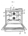
- FIG. 1 is a front view of an oven in an aspect of one or more embodiments
- FIG. 2 is a schematic longitudinal-sectional view of the oven of FIG. 1 .
- an oven 1 in an embodiment includes an inner case in which a cooking chamber 30 is formed, and an outer case 10 connected to the outer surface of the inner case 11 and forming the external appearance of the oven 1.
- the front surface of the cooking chamber 30 is opened so that an object to be cooked may enter and exit the cooking chamber 30, and the opened front surface of the cooling chamber 30 may be opened and closed by a door 20.
- the door 20 may be rotatably hinged to the lower portion of the inner case 11, and be provided with a handle 21 so as to be easily opened and closed.
- the door 20 may include plural door glasses 22a, 22b, 22c and 22d and a door frame 23 supporting the plural door glasses 22a, 22b, 22c and 22d, and a gap of a designated interval may be formed between the plural door glasses 22a, 22b, 22c and 22d. These gaps form channels 24a, 24b and 24c in which air flows, and air may flow in the upward direction through the channels 24a, 24b and 24c.
- air passing through a discharge hole 66 of an exhaust duct 60 located above the channels 24a, 24b and 24c has relatively low pressure, and thus air of the channels 24a, 24b and 24c may be sucked in the upward direction due to a pressure difference and be discharged to an area in front of the oven 1 together with air discharged from the discharge hole 66 of the exhaust duct 60.
- cooling of the door 20 may be executed.
- Racks 32 on which an object to be cooked is placed may be mounted in the cooking chamber 30.
- the racks 32 may be mounted on guide rails 31 provided on both inner side surfaces of the inner case 11 of the cooking chamber 30.
- At least one heater 33 may be provided in the cooking chamber 30 so as to heat the object to be cooked. Further, circulation fans 35 circulating air of the cooking chamber 30 and circulation motors 34 to drive the circulation fans 35 may be provided in the rear portion of the cooking chamber 30. A fan cover 36 to cover the circulation fans 35 may be provided in front of the circulation fans 35, and through holes 37 through which air flows may be formed on the fan cover 36.
- a control panel 41 displaying various operating information of the oven 1 and inputting the operating information may be provided at the upper portion of the front surface of the outer case 10.
- the oven 1 further includes a component chamber 40 which may accommodate various electronic components 42 and 43 (with reference to FIG. 7 ) controlling the operation of the oven 1.
- the electronic components 42 and 43 may include a display circuit board 42 controlling the control panel 41 and a main circuit board 43 controlling the operation of the heater 33 and the circulation motors 34.
- Such a component chamber 40 may be provided above the cooking chamber 30, and an adiabatic material 44 may be provided between the cooking chamber 30 and the component chamber 40.
- a component chamber cooling apparatus 50 cooling the component chamber 40 by circulating air of the component chamber 40 may be provided in the component chamber 40.
- the component chamber cooling apparatus 50 includes the exhaust duct 60 sucking in air from the component chamber 40 and exhausting the air to the area in front of the oven 1, a fan 70 forcibly blowing the air of the component chamber 40, a motor 86 to drive the fan 70, and a support bracket 90 to support the motor 80.
- a suction hole 65 to suck air is formed on the upper portion of the exhaust duct 60, and the discharge hole 66 to discharge air is formed on the front portion of the exhaust duct 60.
- the discharge hole 66 may discharge air to the area in front of the oven 1.
- the component chamber cooling apparatus 50 may cool the component chamber 40 by sucking in air from the component chamber 40 and discharging the sucked air to the area in front of the oven 1.
- the exhaust duct 60 may be formed in a venturi pipe type having the height which is gradually lowered in the forward direction of the oven 1 and the cross-sectional area which is gradually decreased in the forward direction of the oven 1. Therefore, the speed of air in the exhaust duct 60 may be raised and the pressure of the air in the exhaust duct 60 may be decreased in the forward direction of the oven 1.
- Such a component chamber cooling apparatus 50 may occupy most of the height of the component chamber 40, as shown in FIG. 2 . Therefore, in order to increase the capacity of the cooking chamber 30 while uniformly maintaining the overall height of the oven 1, lowering of the height of the component chamber cooling apparatus 50 is required.
- the component chamber cooling apparatus 50 of the oven 1 in accordance with an embodiment is designed to achieve this objective, and a detailed configuration thereof will be described in detail below.
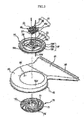
- FIG. 3 is an exploded perspective view of the component chamber cooling apparatus of the oven of FIG. 1
- FIG. 4 is a plan view of the component chamber cooling apparatus of the oven of FIG. 1
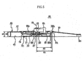
- FIG. 5 is a cross-sectional view taken along the line I-I of FIG. 4
- FIG. 6 is a cross-sectional view taken along the line II-II of FIG. 4
- FIG. 7 is a view illustrating flow of cool air in the component chamber cooling apparatus of FIG.1 .
- the component chamber cooling apparatus 50 in an embodiment includes the exhaust duct 60 guiding air of the component chamber 40 to the area in front of the oven 1, the fan 70 forcibly blowing the air of the component chamber 40, the motor 80 to drive the fan 70, and the support bracket 90 to support the motor 80.
- the exhaust duct 60 includes a scroll part 63, the radius of which is gradually increased in the clockwise direction, and a discharge part 64 formed at the rear portion of the scroll part 63.
- the suction hole 65 through which air is sucked into the exhaust duct 60 is formed on the upper portion of the scroll part 63, and the discharge hole 66 through which air is discharged to the outside of the exhaust duct 60 is formed on the discharge part 64. Therefore, air sucked into the exhaust duct 60 through the suction hole 65 formed on the upper portion of the exhaust duct 60 may be guided to the discharge part 64 by the scroll part 63 and be discharged to the area in front of the oven through the discharge hole 66.
- the discharge part 64 may be formed such that the height of the discharge part 64 is gradually lowered and the cross-sectional area of the discharge part 64 is gradually decreased in the direction toward the discharge hole 66 so as to exhibit venturi effects.
- the fan 70 may be a centrifugal fan or a turbo fan which sucks air at the upper portion thereof and discharges air in the radial direction.
- the fan 70 may be disposed at the inside of the exhaust duct 60.
- the fan 70 may include a rotary plate 71, a hub 72 protruding upwardly from the center of the rotary plate 71, plural blades 73 formed inwardly from the edge of the rotary plate 71, and a shroud 74 connecting the tips of the upper ends of the plural blades 73.
- the hub 72 may be formed in a conical shape, the radius of which is increased in the downward direction, and may diffuse air sucked through the upper portion thereof in the radial direction.
- the air diffused in the radial direction by the hub 72 may be discharged to the plural blades 73 in the radial direction of the fan 70.
- the motor 80 generates rotating force to drive the fan 70, and may include a stator 82 and a rotor 81.
- the stator 82 may include a bobbin 85 on which a coil 86 is wound, and a core 83 generating a magnetic field when current is applied to the coil 86.
- the rotor 81 may be rotated in one direction by the magnetic field formed by the core 83.
- One end of a rotary shaft 87 is connected to the rotor 81, and the rotary shaft 87 may be rotated together with the rotor 81.
- the other end of the rotary shaft 87 is connected to the fan 70.
- Such a motor 80 may be supported by the support bracket 90.
- the support bracket 90 may include a base unit 97 supported by the exhaust duct 60 around the suction hole 65, a motor combining unit 91 separated from the base part 97 and combined with the motor 80, and bridge parts 96 connecting the base unit 97 and the motor combining unit 91.
- the base unit 97 may have an almost donut shape and be combined with the exhaust duct 60 around the suction hole 65.
- the base unit 97 may include a bell-mouthed part 98 forming an inner suction hole 98a through which air is sucked into the exhaust duct 60.
- the bell-mouthed part 98 has an almost arc-shaped cross-section, and may prevent formation of a vortex of air introduced into the exhaust duct 60 and thus reduce noise.
- a planar part 99a extended almost horizontally may be provided at the outside of the bell-mouthed part 98, and a curved part 99b gently inclined may be provided at the outside of the planar part 99a.
- the support bracket 90 may be supported by the exhaust duct 60 by placing the curved part 99b on the exhaust duct 60 around the suction hole 65.
- Fixing protrusions 90a protruded downwardly are formed on the support bracket 90, fixing holes 60a into which the fixing protrusions 90a are inserted are formed on the exhaust duct 60, and the support bracket 90 may be combined with the exhaust duct 60 by inserting the fixing protrusions 90a into the fixing holes 60a.
- the radius R1 of the suction hole 65 of the exhaust duct 60 may be greater than the radius R 2 of the fan 70 in consideration of a space in which the base unit 97 will be disposed.
- the motor-combining unit 91 may include a core support part 92 on which the core 83 of the motor 80 is mounted, and a core guide part 94 extended upwardly from the edge of the core support part 92.
- the core guide part 94 may have three surfaces except for the surface with which the bobbin 85 of the motor 80 is combined.
- the core support part 92 and the core guide part 94 may form an accommodation space 95 accommodating the core 83.
- Fastening holes 83a may be formed on the stator 83 of the motor 82, and fastening holes 92a corresponding to the fastening holes 83a may be formed on the core support part 92 of the motor combining unit 91. Therefore, the motor 82 may be firmly fastened to the motor combining unit 91 by inserting fastening members, such as screws, into the fastening holes 83a and the fastening holes 92a.
- the support bracket 90 may include the bridge parts 96 connecting the base unit 96 and the motor combining unit 91.
- this embodiment describes four bridge parts 96, the number of the bridge parts 96 is not limited thereto but rather may be less than three or more than five.
- the height H2 of the lower end 84 of the motor core 83 combined with the motor combining unit 91 may be equal to or lower than the height H1 of the upper end 61 of the exhaust duct 60.
- the heights H1 and H2 are set based on a bottom surface 45 of the component chamber, but may be set based on the bottom surface supporting the oven.
- the bridge parts 90 may be formed horizontally so that the height H2 of the lower end 84 of the motor core 83 is equal to or lower than the height H1 of the upper end 61 of the exhaust duct 60. Otherwise, although not shown in the drawings, the bridge parts 90 may be inclined downwardly in a direction from the base unit 97 to the motor combining unit 91.
- the height of the component chamber cooling apparatus 50 occupying most of the height of the component chamber 40 may be generally lowered. Therefore, the height of the component chamber 40 may be lowered, and the capacity of the cooking chamber 30 may be increased by increasing the height of the cooking chamber 30 as much as the lowered height of the component chamber 40.
- the motor 80 and the fan 70 may be close to each other, and thus cooling of the motor 80 may be more effectively carried out.
- the height H2 of the upper end 93 of the core support part 92 may be equal to the height H2 of the lower end 84 of the motor core 83 combined with the motor combining unit 91. Therefore, in accordance with an embodiment, the height H2 of the upper end 93 of the core support part 92 may be equal to or lower than the height H1 or the upper end 61 of the exhaust duct 60.
- Such a support bracket 90 including the base unit 97, the motor combining unit 91 and the bridge parts 96 may be integrally formed.
- the support bracket 90 may be integrally formed by injection molding using a resin material.
- FIG. 8 is an exploded perspective view of a component chamber cooling apparatus of an oven in accordance with an embodiment.
- FIG. 8 a component chamber cooling apparatus 150 of an oven in accordance with an embodiment will be described. A description of components which are substantially the same as an embodiment in Figure 2 , for example, will be omitted for convenience.
- the component chamber cooling apparatus 150 in accordance with an embodiment includes a fan 180 forcibly blowing air of a component chamber, a-motor 190 driving the fan 180, and an exhaust duct 160 guiding air of the component chamber.
- the fan 180 has the same configuration as the fan 70 in accordance with an embodiment shown in Figure 3 ,for example, and a detailed description thereof will thus be omitted.
- the motor 190 also has the same configuration as the motor 80 in accordance with an embodiment shown in Figure 3 , and a detailed description thereof will thus be omitted.
- the exhaust duct 160 includes a scroll part 163, the radius of which is gradually increased in the clockwise direction, and a discharge part 164 formed at the rear portion of the scroll part 163.
- a suction hole 165 through which air is sucked into the exhaust duct 160 may be formed on the upper portion of the scroll part 163, and a discharge hole 166 may be formed at the end of the discharge part 164. Therefore, air sucked into the exhaust duct 160 through the suction hole 165 on the upper portion of the exhaust duct 160 may be guided to the discharge part 164 by the scroll part 163 and be discharged to the outside of the exhaust duct 160 through the discharge hole 166.
- a motor combining unit 167 may include a core support part 168 on which a core 193 of the motor 190 is mounted, and a core guide part 170 extended upwardly from the edge of the core support part 168.
- the core support part 168 and the core guide part 170 may form an accommodation space accommodating the core 193 of the motor 190.
- Fastening holes 168a maybe formed on the core support part 168, fastening holes 193a may be formed on the core 193 of the motor 190, and the motor 190 may be firmly fastened to the motor combining unit 167 by inserting fastening members, such as screws, into the fastening holes 168a and the fastening holes 193a.
- the height of the upper end of the core support part 168 may be equal to or lower than the height of the upper end of the exhaust duct 160. Therefore, the height of the lower end of the motor core 193 placed on the core support part 168 may also be equal to or lower than the height of the upper end of the exhaust duct 160.
- the effects thereby are equal to those of an embodiment shown in Figure 2 , for example, and a detailed description will thus be omitted.
- a bell-mouthed part 173 forming the suction hole 165 and bridge parts 172 supporting the motor combining unit 167 may be provided on the exhaust duct 160.
- the bell-mouthed part 173 has an almost arc-shaped cross-section, and may prevent formation of a vortex of air passing through the suction hole 165 and thus reduce noise.
- a planar part 174a extended almost horizontally may be provided at the outside of the bell-mouthed part 173, and a curved part 174b gently inclined may be provided at the outside of the planar part 174a.
- each of the bridge parts 172 is connected to the bell-mouthed part 173, the other end of each of the bridge parts 172 is connected to the motor combining unit 167, and thus the bridge parts 172 may support the motor combining unit 167.
- plural bridge parts 172 may be provided.
- the bridge parts 172 may be formed almost horizontally, or be inclined downwardly in a direction from the bell-mouthed part 173 to the motor combining unit 167.
- Such an exhaust duct 160 including the motor combining unit 167, the bell-mouthed part 173 and the bridge parts 172 may be integrally formed.
- the exhaust duct 160 may be formed by injection molding using a resin material.
- a cooking appliance in accordance with an embodiment slims a component chamber and may thus provide an oven designed such that the capacity of a cooking chamber is increased.
- a motor and a fan are disposed close to each other, and thus cooling of the motor itself may be effectively executed.
- a bell-mouthed part is provided at a suction hole of an exhaust duct, and thus noise may be reduced.
Landscapes
- Engineering & Computer Science (AREA)
- Chemical & Material Sciences (AREA)
- Combustion & Propulsion (AREA)
- Mechanical Engineering (AREA)
- General Engineering & Computer Science (AREA)
- Induction Heating Cooking Devices (AREA)
- Cookers (AREA)
Description
- The present invention relates to cooking appliances, particularly but not exclusively to the component chamber cooling structure of an oven.
- In general, an oven is a cooking appliance including a cooking chamber, a heating apparatus generating heat, and a fan circulating the heat generated from the heating apparatus to the inside of the cooking chamber, and thus cooking an object to be cooked.
- The document
EP 0 926 448 A2 discloses a cooking appliance comprising a cooking chamber to accommodate an object to be cooked ; a component chamber provided above the cooking chamber; and
a component chamber cooling apparatus provided in the component chamber, the cooling apparatus comprising an exhaust duct including a suction hole , which sucks in air from the component chamber, and a discharge hole, which discharges the sucked air to an area in front of the component chamber; and a fan disposed at the inside of the exhaust duct and forcibly blowing air of the component chamber. - A machine chamber, also referred to as a component chamber, is provided above the cooking chamber in which various electronic components operating the oven are disposed, and a component chamber cooling apparatus preventing damage to the electronic components due to heat from the cooking chamber is provided in the component chamber.
- The component chamber cooling apparatus may include an exhaust duct sucking in air from the component chamber and exhausting the sucked air to an area in front of the oven, a fan forcibly blowing the air of the component chamber through the exhaust duct, and a motor driving the fan.
- In order to increase the capacity of the cooking chamber, the height of the cooking chamber needs to be secured and a design to relatively lower the height of the component chamber is required.
- In an aspect of one or more embodiments, there is provided a cooling structure of a component chamber which relatively enlarges the inner volume of a cooking chamber by slimming the component chamber.
- In an aspect of one or more embodiments, there is provided a cooking appliance which includes a cooking chamber to accommodate an object to be cooked, a component chamber provided above the cooking chamber, an exhaust duct including a suction hole, which sucks in air from the component chamber and a discharge hole, which discharges the sucked air to an area in front of the component chamber, a fan forcibly blowing air of the component chamber, a motor including a stator and a rotor, provided above the fan and driving the fan, the stator including a bobbin on which a coil is wound and a core forming a magnetic field according to current applied to the coil, and a support bracket which is provided at the suction hole, and which supports the motor such that a height of a lower end of the core is equal to or lower than a height of an upper end of the exhaust duct.
- The support bracket may include a base unit supported by the exhaust duct around the suction hole, a motor combining unit separated from the base part so that air passes through a gap between the base unit and the motor combining unit, and bridge parts connecting the base unit and the motor combining unit, and the bridge parts may be formed horizontally or be inclined downwardly in a direction from the base unit to the motor combining unit.
- The motor combining unit may include a core support part on which the core is mounted and a core guide part extended upwardly from the core support part so as to form an accommodation space accommodating the core together with the core support part, and a height of an upper end of the core support part may be equal to or lower than the height of the upper end of the exhaust duct.
- The base unit may include a bell-mouthed part to prevent noise of air sucked into the exhaust duct.
- The base unit may further include a planar part extended horizontally to the outside of the bell-mouthed part, and a curved part extended upwardly from the planar part so as to have a gentle inclination and placed on the exhaust duct.
- The radius of the suction hole may be greater than the radius of the fan.
- The support bracket may be integrally formed.
- In an aspect of one or more embodiments, there is provided a cooking appliance which includes a cooking chamber to accommodate an object to be cooked, a component chamber provided above the cooking chamber, a fan forcibly blowing air of the component chamber, a motor including a stator and a rotor, provided above the fan and driving the fan, the stator including a bobbin on which a coil is wound and a core forming a magnetic field according to current applied to the coil, and an exhaust duct to suck in air from the component chamber and to discharge the sucked air to an area in front of the component chamber, the exhaust duct including a motor combining unit which supports the motor such that the height of the lower end of the core is equal to or lower than the height of the upper end of the exhaust duct.
- The exhaust duct may include bridge parts supporting the motor combining unit, and the bridge parts may be formed horizontally or be inclined downwardly in a direction toward the motor combining unit.
- The motor combining unit may include a core support part on which the core is mounted and a core guide part extended upwardly from the core support part so as to form an accommodation space accommodating the core together with the core support part, and a height of an upper end of the core support part may be equal to or lower than the height of the upper end of the exhaust duct.
- The exhaust duct may include a bell-mouthed part forming a suction hole.
- The exhaust duct may be integrally formed.
- These and/or other aspects will become apparent and more readily appreciated from the following description of embodiments, taken in conjunction with the accompanying drawings of which:
-
FIG. 1 is a front view of an oven in accordance with an embodiment; -
FIG. 2 is a schematic longitudinal-sectional view of the oven ofFIG. 1 ; -
FIG. 3 is an exploded perspective view of a component chamber cooling apparatus of the oven ofFIG. 1 ; -
FIG. 4 is a plan view of the component chamber cooling apparatus of the oven ofFIG. 1 ; -
FIG. 5 is a cross-sectional view taken along the line I-I ofFIG. 4 ; -
FIG. 6 is a cross-sectional view taken along the line II-II ofFIG. 4 ; -
FIG. 7 is a view illustrating flow of cool air in the component chamber cooling apparatus ofFIG. 1 ; and -
FIG. 8 is an exploded perspective view of a component chamber cooling apparatus of an oven in an embodiment. - Reference will now be made in detail to embodiments, examples of which are illustrated in the accompanying drawings, wherein like reference numerals refer to like elements throughout.
-
FIG. 1 is a front view of an oven in an aspect of one or more embodiments, andFIG. 2 is a schematic longitudinal-sectional view of the oven ofFIG. 1 . - With reference to
FIGS. 1 and2 , anoven 1 in an embodiment includes an inner case in which acooking chamber 30 is formed, and an outer case 10 connected to the outer surface of the inner case 11 and forming the external appearance of theoven 1. - The front surface of the
cooking chamber 30 is opened so that an object to be cooked may enter and exit thecooking chamber 30, and the opened front surface of thecooling chamber 30 may be opened and closed by adoor 20. Thedoor 20 may be rotatably hinged to the lower portion of the inner case 11, and be provided with a handle 21 so as to be easily opened and closed. - The
door 20 may includeplural door glasses 22a, 22b, 22c and 22d and a door frame 23 supporting theplural door glasses 22a, 22b, 22c and 22d, and a gap of a designated interval may be formed between theplural door glasses 22a, 22b, 22c and 22d. These gaps formchannels channels - Although this will be described in detail later, air passing through a
discharge hole 66 of anexhaust duct 60 located above thechannels channels oven 1 together with air discharged from thedischarge hole 66 of theexhaust duct 60. Through such a configuration, cooling of thedoor 20 may be executed. - Racks 32 on which an object to be cooked is placed may be mounted in the
cooking chamber 30. The racks 32 may be mounted onguide rails 31 provided on both inner side surfaces of the inner case 11 of thecooking chamber 30. - At least one
heater 33 may be provided in thecooking chamber 30 so as to heat the object to be cooked. Further, circulation fans 35 circulating air of thecooking chamber 30 and circulation motors 34 to drive the circulation fans 35 may be provided in the rear portion of thecooking chamber 30. Afan cover 36 to cover the circulation fans 35 may be provided in front of the circulation fans 35, and throughholes 37 through which air flows may be formed on thefan cover 36. - A control panel 41 displaying various operating information of the
oven 1 and inputting the operating information may be provided at the upper portion of the front surface of the outer case 10. - The
oven 1 further includes acomponent chamber 40 which may accommodate various electronic components 42 and 43 (with reference toFIG. 7 ) controlling the operation of theoven 1. The electronic components 42 and 43 may include a display circuit board 42 controlling the control panel 41 and a main circuit board 43 controlling the operation of theheater 33 and the circulation motors 34. - Such a
component chamber 40 may be provided above thecooking chamber 30, and an adiabatic material 44 may be provided between thecooking chamber 30 and thecomponent chamber 40. - Since the electronic components 42 and 43 of the
component chamber 40 are very sensitive to heat, a componentchamber cooling apparatus 50 cooling thecomponent chamber 40 by circulating air of thecomponent chamber 40 may be provided in thecomponent chamber 40. - The component
chamber cooling apparatus 50 includes theexhaust duct 60 sucking in air from thecomponent chamber 40 and exhausting the air to the area in front of theoven 1, afan 70 forcibly blowing the air of thecomponent chamber 40, amotor 86 to drive thefan 70, and asupport bracket 90 to support themotor 80. - A
suction hole 65 to suck air is formed on the upper portion of theexhaust duct 60, and thedischarge hole 66 to discharge air is formed on the front portion of theexhaust duct 60. Thedischarge hole 66 may discharge air to the area in front of theoven 1. Through such a configuration, the componentchamber cooling apparatus 50 may cool thecomponent chamber 40 by sucking in air from thecomponent chamber 40 and discharging the sucked air to the area in front of theoven 1. - Here, the
exhaust duct 60 may be formed in a venturi pipe type having the height which is gradually lowered in the forward direction of theoven 1 and the cross-sectional area which is gradually decreased in the forward direction of theoven 1. Therefore, the speed of air in theexhaust duct 60 may be raised and the pressure of the air in theexhaust duct 60 may be decreased in the forward direction of theoven 1. - Such a component
chamber cooling apparatus 50 may occupy most of the height of thecomponent chamber 40, as shown inFIG. 2 . Therefore, in order to increase the capacity of thecooking chamber 30 while uniformly maintaining the overall height of theoven 1, lowering of the height of the componentchamber cooling apparatus 50 is required. - The component
chamber cooling apparatus 50 of theoven 1 in accordance with an embodiment is designed to achieve this objective, and a detailed configuration thereof will be described in detail below. -
FIG. 3 is an exploded perspective view of the component chamber cooling apparatus of the oven ofFIG. 1 ,FIG. 4 is a plan view of the component chamber cooling apparatus of the oven ofFIG. 1 ,FIG. 5 is a cross-sectional view taken along the line I-I ofFIG. 4 ,FIG. 6 is a cross-sectional view taken along the line II-II ofFIG. 4 , andFIG. 7 is a view illustrating flow of cool air in the component chamber cooling apparatus ofFIG.1 . - With reference to
FIGS. 3 to 7 , the componentchamber cooling apparatus 50 in an embodiment includes theexhaust duct 60 guiding air of thecomponent chamber 40 to the area in front of theoven 1, thefan 70 forcibly blowing the air of thecomponent chamber 40, themotor 80 to drive thefan 70, and thesupport bracket 90 to support themotor 80. - The
exhaust duct 60 includes a scroll part 63, the radius of which is gradually increased in the clockwise direction, and a discharge part 64 formed at the rear portion of the scroll part 63. Thesuction hole 65 through which air is sucked into theexhaust duct 60 is formed on the upper portion of the scroll part 63, and thedischarge hole 66 through which air is discharged to the outside of theexhaust duct 60 is formed on the discharge part 64. Therefore, air sucked into theexhaust duct 60 through thesuction hole 65 formed on the upper portion of theexhaust duct 60 may be guided to the discharge part 64 by the scroll part 63 and be discharged to the area in front of the oven through thedischarge hole 66. Further, the discharge part 64 may be formed such that the height of the discharge part 64 is gradually lowered and the cross-sectional area of the discharge part 64 is gradually decreased in the direction toward thedischarge hole 66 so as to exhibit venturi effects. - The
fan 70 may be a centrifugal fan or a turbo fan which sucks air at the upper portion thereof and discharges air in the radial direction. Thefan 70 may be disposed at the inside of theexhaust duct 60. Thefan 70 may include a rotary plate 71, ahub 72 protruding upwardly from the center of the rotary plate 71,plural blades 73 formed inwardly from the edge of the rotary plate 71, and ashroud 74 connecting the tips of the upper ends of theplural blades 73. - The
hub 72 may be formed in a conical shape, the radius of which is increased in the downward direction, and may diffuse air sucked through the upper portion thereof in the radial direction. The air diffused in the radial direction by thehub 72 may be discharged to theplural blades 73 in the radial direction of thefan 70. - The
motor 80 generates rotating force to drive thefan 70, and may include a stator 82 and arotor 81. The stator 82 may include abobbin 85 on which acoil 86 is wound, and a core 83 generating a magnetic field when current is applied to thecoil 86. Therotor 81 may be rotated in one direction by the magnetic field formed by thecore 83. One end of arotary shaft 87 is connected to therotor 81, and therotary shaft 87 may be rotated together with therotor 81. The other end of therotary shaft 87 is connected to thefan 70. - Such a
motor 80 may be supported by thesupport bracket 90. Thesupport bracket 90 may include a base unit 97 supported by theexhaust duct 60 around thesuction hole 65, a motor combining unit 91 separated from the base part 97 and combined with themotor 80, andbridge parts 96 connecting the base unit 97 and the motor combining unit 91. - The base unit 97 may have an almost donut shape and be combined with the
exhaust duct 60 around thesuction hole 65. The base unit 97 may include a bell-mouthed part 98 forming aninner suction hole 98a through which air is sucked into theexhaust duct 60. The bell-mouthed part 98 has an almost arc-shaped cross-section, and may prevent formation of a vortex of air introduced into theexhaust duct 60 and thus reduce noise. - A
planar part 99a extended almost horizontally may be provided at the outside of the bell-mouthed part 98, and a curved part 99b gently inclined may be provided at the outside of theplanar part 99a. Thesupport bracket 90 may be supported by theexhaust duct 60 by placing the curved part 99b on theexhaust duct 60 around thesuction hole 65. - Fixing
protrusions 90a protruded downwardly are formed on thesupport bracket 90, fixing holes 60a into which the fixingprotrusions 90a are inserted are formed on theexhaust duct 60, and thesupport bracket 90 may be combined with theexhaust duct 60 by inserting the fixingprotrusions 90a into the fixing holes 60a. - As shown in
FIGS. 5 and6 , the radius R1 of thesuction hole 65 of theexhaust duct 60 may be greater than the radius R2 of thefan 70 in consideration of a space in which the base unit 97 will be disposed. - The motor-combining unit 91 may include a
core support part 92 on which thecore 83 of themotor 80 is mounted, and acore guide part 94 extended upwardly from the edge of thecore support part 92. The core guidepart 94 may have three surfaces except for the surface with which thebobbin 85 of themotor 80 is combined. Thecore support part 92 and thecore guide part 94 may form an accommodation space 95 accommodating the core 83. - Fastening holes 83a may be formed on the
stator 83 of the motor 82, andfastening holes 92a corresponding to the fastening holes 83a may be formed on thecore support part 92 of the motor combining unit 91. Therefore, the motor 82 may be firmly fastened to the motor combining unit 91 by inserting fastening members, such as screws, into the fastening holes 83a and thefastening holes 92a. - Since the base unit 97 and the motor combining unit 91 are separated from each other, as described above, the
support bracket 90 may include thebridge parts 96 connecting thebase unit 96 and the motor combining unit 91. Although this embodiment describes fourbridge parts 96, the number of thebridge parts 96 is not limited thereto but rather may be less than three or more than five. - As shown in
FIGS. 5 and6 , the height H2 of thelower end 84 of themotor core 83 combined with the motor combining unit 91 may be equal to or lower than the height H1 of theupper end 61 of theexhaust duct 60. - Here, the heights H1 and H2 are set based on a bottom surface 45 of the component chamber, but may be set based on the bottom surface supporting the oven.
- Further, as shown in
FIG. 6 , thebridge parts 90 may be formed horizontally so that the height H2 of thelower end 84 of themotor core 83 is equal to or lower than the height H1 of theupper end 61 of theexhaust duct 60. Otherwise, although not shown in the drawings, thebridge parts 90 may be inclined downwardly in a direction from the base unit 97 to the motor combining unit 91. - As described above, by disposing the
motor core 83 such that the height H2 of thelower end 84 of themotor core 83 is equal to or lower than the height H1 of theupper end 61 of theexhaust duct 60, the height of the componentchamber cooling apparatus 50 occupying most of the height of thecomponent chamber 40 may be generally lowered. Therefore, the height of thecomponent chamber 40 may be lowered, and the capacity of thecooking chamber 30 may be increased by increasing the height of thecooking chamber 30 as much as the lowered height of thecomponent chamber 40. - Further, by disposing the
motor core 83 such that the height H2 of thelower end 84 of themotor core 83 is equal to or lower than the height H1 of theupper end 61 of theexhaust duct 60, themotor 80 and thefan 70 may be close to each other, and thus cooling of themotor 80 may be more effectively carried out. - Since the
motor core 83 is placed on thecore support part 92 of the motor combining unit 91, the height H2 of theupper end 93 of thecore support part 92 may be equal to the height H2 of thelower end 84 of themotor core 83 combined with the motor combining unit 91. Therefore, in accordance with an embodiment, the height H2 of theupper end 93 of thecore support part 92 may be equal to or lower than the height H1 or theupper end 61 of theexhaust duct 60. - Such a
support bracket 90 including the base unit 97, the motor combining unit 91 and thebridge parts 96 may be integrally formed. Thesupport bracket 90 may be integrally formed by injection molding using a resin material. -
FIG. 8 is an exploded perspective view of a component chamber cooling apparatus of an oven in accordance with an embodiment. - With reference to
FIG. 8 , a componentchamber cooling apparatus 150 of an oven in accordance with an embodiment will be described. A description of components which are substantially the same as an embodiment inFigure 2 , for example, will be omitted for convenience. - The component
chamber cooling apparatus 150 in accordance with an embodiment includes afan 180 forcibly blowing air of a component chamber, a-motor 190 driving thefan 180, and anexhaust duct 160 guiding air of the component chamber. - The
fan 180 has the same configuration as thefan 70 in accordance with an embodiment shown inFigure 3 ,for example, and a detailed description thereof will thus be omitted. Themotor 190 also has the same configuration as themotor 80 in accordance with an embodiment shown inFigure 3 , and a detailed description thereof will thus be omitted. - The
exhaust duct 160 includes ascroll part 163, the radius of which is gradually increased in the clockwise direction, and adischarge part 164 formed at the rear portion of thescroll part 163. Asuction hole 165 through which air is sucked into theexhaust duct 160 may be formed on the upper portion of thescroll part 163, and adischarge hole 166 may be formed at the end of thedischarge part 164. Therefore, air sucked into theexhaust duct 160 through thesuction hole 165 on the upper portion of theexhaust duct 160 may be guided to thedischarge part 164 by thescroll part 163 and be discharged to the outside of theexhaust duct 160 through thedischarge hole 166. - A
motor combining unit 167 may include acore support part 168 on which acore 193 of themotor 190 is mounted, and acore guide part 170 extended upwardly from the edge of thecore support part 168. Thecore support part 168 and thecore guide part 170 may form an accommodation space accommodating thecore 193 of themotor 190. - Fastening holes 168a maybe formed on the
core support part 168, fastening holes 193a may be formed on thecore 193 of themotor 190, and themotor 190 may be firmly fastened to themotor combining unit 167 by inserting fastening members, such as screws, into the fastening holes 168a and the fastening holes 193a. - The height of the upper end of the
core support part 168 may be equal to or lower than the height of the upper end of theexhaust duct 160. Therefore, the height of the lower end of themotor core 193 placed on thecore support part 168 may also be equal to or lower than the height of the upper end of theexhaust duct 160. The effects thereby are equal to those of an embodiment shown inFigure 2 , for example, and a detailed description will thus be omitted. - Further, a bell-
mouthed part 173 forming thesuction hole 165 andbridge parts 172 supporting themotor combining unit 167 may be provided on theexhaust duct 160. - The bell-
mouthed part 173 has an almost arc-shaped cross-section, and may prevent formation of a vortex of air passing through thesuction hole 165 and thus reduce noise. Aplanar part 174a extended almost horizontally may be provided at the outside of the bell-mouthed part 173, and a curved part 174b gently inclined may be provided at the outside of theplanar part 174a. - One end of each of the
bridge parts 172 is connected to the bell-mouthed part 173, the other end of each of thebridge parts 172 is connected to themotor combining unit 167, and thus thebridge parts 172 may support themotor combining unit 167. Here,plural bridge parts 172 may be provided. Thebridge parts 172 may be formed almost horizontally, or be inclined downwardly in a direction from the bell-mouthed part 173 to themotor combining unit 167. - Such an
exhaust duct 160 including themotor combining unit 167, the bell-mouthed part 173 and thebridge parts 172 may be integrally formed. Theexhaust duct 160 may be formed by injection molding using a resin material. - As is apparent from the above description, a cooking appliance in accordance with an embodiment slims a component chamber and may thus provide an oven designed such that the capacity of a cooking chamber is increased.
- Further, a motor and a fan are disposed close to each other, and thus cooling of the motor itself may be effectively executed.
- Further, a bell-mouthed part is provided at a suction hole of an exhaust duct, and thus noise may be reduced.
- Although a few embodiments have been shown and described, it would be appreciated by those skilled in the art that changes may be made in these embodiments without departing from the principles of the invention, the scope of which is defined in the claims.
Claims (7)
- A cooking appliance (1) comprising:a cooking chamber (30) to accommodate an object to be cooked;a component chamber (40) provided above the cooking chamber; anda component chamber cooling apparatus (50) provided in the component chamber, the component chamber cooling apparatus comprising:an exhaust duct (60) including a suction hole (65), which sucks in air from the component chamber, and a discharge hole (66), which discharges the sucked air to an area in front of the component chamber;a fan (70) disposed at the inside of the exhaust duct and forcibly blowing air of the component chamber;a motor (80) including a stator (82) and a rotor (81), provided above the fan and driving the fan, the stator including a bobbin (85) on which a coil (86) is wound and a core (83) forming a magnetic field according to current applied to the coil; andcharacterized by a support bracket (90) which is provided at the suction hole, and which supports the motor such that a height of a lower end of the core is equal to or lower than a height of an upper end of the exhaust duct, the height of the upper end of the exhaust duct and the height of the lower end of the core being set based on a bottom surface (45) of the component chamber.
- The cooking appliance according to claim 1, wherein the support bracket includes a base unit (97) supported by the exhaust duct around the suction hole, a motor combining unit (91) separated from the base part so that air passes through a gap between the base unit and the motor combining unit, and bridge parts (96) connecting the base unit and the motor combining unit,
wherein the bridge parts are formed horizontally, or are inclined downwardly in a direction from the base unit to the motor combining unit. - The cooking appliance according to claim 2, wherein the motor combining unit includes a core support part (92) on which the core is mounted, and a core guide part (94) extended upwardly from the core support part so as to form an accommodation space (95) accommodating the core together with the core support part,
wherein a height of an upper end of the core support part is equal to or lower than the height of the upper end of the exhaust duct. - The cooking appliance according to claim 3, wherein the base unit includes a bell-mouthed part (98) to prevent noise of air sucked into the exhaust duct.
- The cooking appliance according to claim 4, wherein the base unit further includes a planar part (99a) extended horizontally to the outside of the bell-mouthed part, and a curved part (99b) extended upwardly from the planar part so as to have a gentle inclination and placed on the exhaust duct.
- The cooking appliance according to any one of the preceding claims, wherein the radius of the suction hole is greater than the radius of the fan.
- The cooking appliance according to any one of the preceding claims, wherein the support bracket is integrally formed.
Applications Claiming Priority (1)
| Application Number | Priority Date | Filing Date | Title |
|---|---|---|---|
| KR1020120065357A KR20130142281A (en) | 2012-06-19 | 2012-06-19 | Cooking appliance |
Publications (2)
| Publication Number | Publication Date |
|---|---|
| EP2677241A1 EP2677241A1 (en) | 2013-12-25 |
| EP2677241B1 true EP2677241B1 (en) | 2016-09-07 |
Family
ID=48672406
Family Applications (1)
| Application Number | Title | Priority Date | Filing Date |
|---|---|---|---|
| EP13172241.5A Not-in-force EP2677241B1 (en) | 2012-06-19 | 2013-06-17 | Cooking appliance |
Country Status (4)
| Country | Link |
|---|---|
| US (1) | US20130333685A1 (en) |
| EP (1) | EP2677241B1 (en) |
| KR (1) | KR20130142281A (en) |
| CN (1) | CN103505069B (en) |
Families Citing this family (22)
| Publication number | Priority date | Publication date | Assignee | Title |
|---|---|---|---|---|
| EP2846100B1 (en) * | 2013-09-10 | 2018-05-30 | Electrolux Appliances Aktiebolag | Cooling and exhaust system for a cooking oven |
| US20150241069A1 (en) * | 2014-02-27 | 2015-08-27 | Electrolux Home Products, Inc. | Wall oven cooling system |
| KR102208562B1 (en) | 2014-07-22 | 2021-01-28 | 삼성전자주식회사 | Oven |
| EP2977682B1 (en) * | 2014-07-25 | 2018-05-30 | Electrolux Appliances Aktiebolag | Oven door, oven comprising an oven door and method for displaying information at an oven door |
| CN104207659A (en) * | 2014-08-14 | 2014-12-17 | 宁波欧燕电器有限公司 | Built-in oven |
| CN104490293B (en) * | 2014-12-18 | 2017-01-18 | 磐吉奥(湖南)工业有限公司 | double-layer oven |
| KR101707749B1 (en) * | 2015-09-21 | 2017-02-16 | 엘지전자 주식회사 | Cooking appliance |
| CN110200516A (en) | 2017-08-09 | 2019-09-06 | 沙克忍者运营有限责任公司 | Cooking system |
| USD914436S1 (en) | 2018-06-19 | 2021-03-30 | Sharkninja Operating Llc | Air diffuser with food preparation pot |
| USD883015S1 (en) | 2018-08-09 | 2020-05-05 | Sharkninja Operating Llc | Food preparation device and parts thereof |
| USD883014S1 (en) | 2018-08-09 | 2020-05-05 | Sharkninja Operating Llc | Food preparation device |
| USD903413S1 (en) | 2018-08-09 | 2020-12-01 | Sharkninja Operating Llc | Cooking basket |
| USD934027S1 (en) | 2018-08-09 | 2021-10-26 | Sharkninja Operating Llc | Reversible cooking rack |
| US11033146B2 (en) | 2019-02-25 | 2021-06-15 | Sharkninja Operating Llc | Cooking device and components thereof |
| WO2020176477A1 (en) | 2019-02-25 | 2020-09-03 | Sharkninja Operating Llc | Cooking system with guard |
| USD982375S1 (en) | 2019-06-06 | 2023-04-04 | Sharkninja Operating Llc | Food preparation device |
| USD918654S1 (en) | 2019-06-06 | 2021-05-11 | Sharkninja Operating Llc | Grill plate |
| US11647861B2 (en) | 2020-03-30 | 2023-05-16 | Sharkninja Operating Llc | Cooking device and components thereof |
| JPWO2022124299A1 (en) * | 2020-12-10 | 2022-06-16 | ||
| CN114608046B (en) * | 2022-03-30 | 2025-08-05 | 杭州老板电器股份有限公司 | Noise-reducing fume suction and exhaust system and integrated stove |
| KR20240018272A (en) * | 2022-08-02 | 2024-02-13 | 엘지전자 주식회사 | Cooking appliance |
| CN115962501A (en) * | 2022-12-16 | 2023-04-14 | 广东合捷电器股份有限公司 | Oil smoke extraction device and integrated kitchen of electromagnetism stove |
Family Cites Families (11)
| Publication number | Priority date | Publication date | Assignee | Title |
|---|---|---|---|---|
| DE2460294C3 (en) * | 1974-12-19 | 1981-07-30 | Bosch-Siemens Hausgeräte GmbH, 7000 Stuttgart | Cooking container for baking, roasting and grilling with a hot air circulation fan, in particular baking and roasting tubes with pyrolytic self-cleaning |
| KR960015463B1 (en) * | 1992-06-01 | 1996-11-14 | 마쯔시다덴기산교 가부시기가이샤 | High frequency heating device |
| US5477036A (en) * | 1994-05-14 | 1995-12-19 | Daewoo Electronics Co., Ltd. | Microwave oven with a cooling arrangement |
| DE19757640C5 (en) * | 1997-12-23 | 2007-04-05 | Ebm-Papst Landshut Gmbh | Device for ventilating a baking oven with baking muffle |
| KR100896263B1 (en) * | 2003-01-03 | 2009-05-08 | 삼성전자주식회사 | Fan motor and microwave with this fan motor |
| KR20050056724A (en) * | 2003-12-10 | 2005-06-16 | 삼성전자주식회사 | Wall mounted type microwave oven |
| ITVR20060001A1 (en) * | 2006-01-10 | 2007-07-11 | Societa Europea Componenti Elettrici Spa | FAN, PARTICULARLY FOR VENTILATION OF KITCHEN OVENS |
| DE102006039130A1 (en) * | 2006-08-21 | 2008-02-28 | BSH Bosch und Siemens Hausgeräte GmbH | Gargerätevorrichtung |
| CN201103936Y (en) * | 2007-09-26 | 2008-08-20 | 美的集团有限公司 | Cooling device for microwave oven |
| US20110017192A1 (en) * | 2007-12-28 | 2011-01-27 | Ergin Arslan | Oven |
| KR101474494B1 (en) * | 2010-03-02 | 2014-12-23 | 삼성전자 주식회사 | Oven |
-
2012
- 2012-06-19 KR KR1020120065357A patent/KR20130142281A/en not_active Ceased
-
2013
- 2013-06-17 EP EP13172241.5A patent/EP2677241B1/en not_active Not-in-force
- 2013-06-18 US US13/920,512 patent/US20130333685A1/en not_active Abandoned
- 2013-06-19 CN CN201310243912.7A patent/CN103505069B/en active Active
Also Published As
| Publication number | Publication date |
|---|---|
| CN103505069A (en) | 2014-01-15 |
| EP2677241A1 (en) | 2013-12-25 |
| US20130333685A1 (en) | 2013-12-19 |
| CN103505069B (en) | 2017-12-12 |
| KR20130142281A (en) | 2013-12-30 |
Similar Documents
| Publication | Publication Date | Title |
|---|---|---|
| EP2677241A1 (en) | Cooking appliance | |
| CN105708347B (en) | oven | |
| US20240027076A1 (en) | An oven | |
| KR101311399B1 (en) | Fan | |
| JP2009008297A (en) | Cooker | |
| JP2011163235A (en) | Centrifugal blower | |
| JP4996994B2 (en) | Cooker | |
| WO2016113118A1 (en) | Apparatus for preparing food ingredients with improved air cooling system | |
| US20220264710A1 (en) | Oven appliance with improved convection cooking performance | |
| JP3966052B2 (en) | Induction heating cooker | |
| EP2235445B1 (en) | A microwave oven | |
| JP5919180B2 (en) | Induction heating cooker | |
| JP6858102B2 (en) | Induction heating cooker | |
| JP6198884B2 (en) | Induction heating cooker | |
| KR19990062539A (en) | Cooker | |
| JP5011001B2 (en) | Cooker | |
| KR101239170B1 (en) | Cooling fan | |
| KR20060117595A (en) | Flow structure of ceiling type air conditioner and ceiling type air conditioner | |
| CN219109224U (en) | Hot air assembly and cooking utensil | |
| CN220859921U (en) | Cooking apparatus | |
| JP5045563B2 (en) | Cooker | |
| CN100512571C (en) | Induction heating cooker | |
| JP4973388B2 (en) | Induction heating cooker | |
| JP6238852B2 (en) | Electromagnetic induction heating cooker | |
| JP5272488B2 (en) | Built-in cooking device |
Legal Events
| Date | Code | Title | Description |
|---|---|---|---|
| PUAI | Public reference made under article 153(3) epc to a published international application that has entered the european phase |
Free format text: ORIGINAL CODE: 0009012 |
|
| AK | Designated contracting states |
Kind code of ref document: A1 Designated state(s): AL AT BE BG CH CY CZ DE DK EE ES FI FR GB GR HR HU IE IS IT LI LT LU LV MC MK MT NL NO PL PT RO RS SE SI SK SM TR |
|
| AX | Request for extension of the european patent |
Extension state: BA ME |
|
| 17P | Request for examination filed |
Effective date: 20140623 |
|
| RBV | Designated contracting states (corrected) |
Designated state(s): AL AT BE BG CH CY CZ DE DK EE ES FI FR GB GR HR HU IE IS IT LI LT LU LV MC MK MT NL NO PL PT RO RS SE SI SK SM TR |
|
| GRAP | Despatch of communication of intention to grant a patent |
Free format text: ORIGINAL CODE: EPIDOSNIGR1 |
|
| INTG | Intention to grant announced |
Effective date: 20160107 |
|
| GRAS | Grant fee paid |
Free format text: ORIGINAL CODE: EPIDOSNIGR3 |
|
| GRAR | Information related to intention to grant a patent recorded |
Free format text: ORIGINAL CODE: EPIDOSNIGR71 |
|
| GRAA | (expected) grant |
Free format text: ORIGINAL CODE: 0009210 |
|
| INTG | Intention to grant announced |
Effective date: 20160721 |
|
| AK | Designated contracting states |
Kind code of ref document: B1 Designated state(s): AL AT BE BG CH CY CZ DE DK EE ES FI FR GB GR HR HU IE IS IT LI LT LU LV MC MK MT NL NO PL PT RO RS SE SI SK SM TR |
|
| REG | Reference to a national code |
Ref country code: GB Ref legal event code: FG4D |
|
| REG | Reference to a national code |
Ref country code: CH Ref legal event code: EP |
|
| REG | Reference to a national code |
Ref country code: IE Ref legal event code: FG4D |
|
| REG | Reference to a national code |
Ref country code: AT Ref legal event code: REF Ref document number: 827226 Country of ref document: AT Kind code of ref document: T Effective date: 20161015 |
|
| REG | Reference to a national code |
Ref country code: DE Ref legal event code: R096 Ref document number: 602013011044 Country of ref document: DE |
|
| REG | Reference to a national code |
Ref country code: LT Ref legal event code: MG4D |
|
| REG | Reference to a national code |
Ref country code: NL Ref legal event code: MP Effective date: 20160907 |
|
| PG25 | Lapsed in a contracting state [announced via postgrant information from national office to epo] |
Ref country code: RS Free format text: LAPSE BECAUSE OF FAILURE TO SUBMIT A TRANSLATION OF THE DESCRIPTION OR TO PAY THE FEE WITHIN THE PRESCRIBED TIME-LIMIT Effective date: 20160907 Ref country code: NO Free format text: LAPSE BECAUSE OF FAILURE TO SUBMIT A TRANSLATION OF THE DESCRIPTION OR TO PAY THE FEE WITHIN THE PRESCRIBED TIME-LIMIT Effective date: 20161207 Ref country code: HR Free format text: LAPSE BECAUSE OF FAILURE TO SUBMIT A TRANSLATION OF THE DESCRIPTION OR TO PAY THE FEE WITHIN THE PRESCRIBED TIME-LIMIT Effective date: 20160907 Ref country code: LT Free format text: LAPSE BECAUSE OF FAILURE TO SUBMIT A TRANSLATION OF THE DESCRIPTION OR TO PAY THE FEE WITHIN THE PRESCRIBED TIME-LIMIT Effective date: 20160907 Ref country code: FI Free format text: LAPSE BECAUSE OF FAILURE TO SUBMIT A TRANSLATION OF THE DESCRIPTION OR TO PAY THE FEE WITHIN THE PRESCRIBED TIME-LIMIT Effective date: 20160907 |
|
| REG | Reference to a national code |
Ref country code: AT Ref legal event code: MK05 Ref document number: 827226 Country of ref document: AT Kind code of ref document: T Effective date: 20160907 |
|
| PG25 | Lapsed in a contracting state [announced via postgrant information from national office to epo] |
Ref country code: ES Free format text: LAPSE BECAUSE OF FAILURE TO SUBMIT A TRANSLATION OF THE DESCRIPTION OR TO PAY THE FEE WITHIN THE PRESCRIBED TIME-LIMIT Effective date: 20160907 Ref country code: GR Free format text: LAPSE BECAUSE OF FAILURE TO SUBMIT A TRANSLATION OF THE DESCRIPTION OR TO PAY THE FEE WITHIN THE PRESCRIBED TIME-LIMIT Effective date: 20161208 Ref country code: SE Free format text: LAPSE BECAUSE OF FAILURE TO SUBMIT A TRANSLATION OF THE DESCRIPTION OR TO PAY THE FEE WITHIN THE PRESCRIBED TIME-LIMIT Effective date: 20160907 Ref country code: NL Free format text: LAPSE BECAUSE OF FAILURE TO SUBMIT A TRANSLATION OF THE DESCRIPTION OR TO PAY THE FEE WITHIN THE PRESCRIBED TIME-LIMIT Effective date: 20160907 Ref country code: LV Free format text: LAPSE BECAUSE OF FAILURE TO SUBMIT A TRANSLATION OF THE DESCRIPTION OR TO PAY THE FEE WITHIN THE PRESCRIBED TIME-LIMIT Effective date: 20160907 |
|
| PG25 | Lapsed in a contracting state [announced via postgrant information from national office to epo] |
Ref country code: EE Free format text: LAPSE BECAUSE OF FAILURE TO SUBMIT A TRANSLATION OF THE DESCRIPTION OR TO PAY THE FEE WITHIN THE PRESCRIBED TIME-LIMIT Effective date: 20160907 Ref country code: RO Free format text: LAPSE BECAUSE OF FAILURE TO SUBMIT A TRANSLATION OF THE DESCRIPTION OR TO PAY THE FEE WITHIN THE PRESCRIBED TIME-LIMIT Effective date: 20160907 |
|
| PG25 | Lapsed in a contracting state [announced via postgrant information from national office to epo] |
Ref country code: AT Free format text: LAPSE BECAUSE OF FAILURE TO SUBMIT A TRANSLATION OF THE DESCRIPTION OR TO PAY THE FEE WITHIN THE PRESCRIBED TIME-LIMIT Effective date: 20160907 Ref country code: IS Free format text: LAPSE BECAUSE OF FAILURE TO SUBMIT A TRANSLATION OF THE DESCRIPTION OR TO PAY THE FEE WITHIN THE PRESCRIBED TIME-LIMIT Effective date: 20170107 Ref country code: SM Free format text: LAPSE BECAUSE OF FAILURE TO SUBMIT A TRANSLATION OF THE DESCRIPTION OR TO PAY THE FEE WITHIN THE PRESCRIBED TIME-LIMIT Effective date: 20160907 Ref country code: CZ Free format text: LAPSE BECAUSE OF FAILURE TO SUBMIT A TRANSLATION OF THE DESCRIPTION OR TO PAY THE FEE WITHIN THE PRESCRIBED TIME-LIMIT Effective date: 20160907 Ref country code: BE Free format text: LAPSE BECAUSE OF FAILURE TO SUBMIT A TRANSLATION OF THE DESCRIPTION OR TO PAY THE FEE WITHIN THE PRESCRIBED TIME-LIMIT Effective date: 20160907 Ref country code: BG Free format text: LAPSE BECAUSE OF FAILURE TO SUBMIT A TRANSLATION OF THE DESCRIPTION OR TO PAY THE FEE WITHIN THE PRESCRIBED TIME-LIMIT Effective date: 20161207 Ref country code: SK Free format text: LAPSE BECAUSE OF FAILURE TO SUBMIT A TRANSLATION OF THE DESCRIPTION OR TO PAY THE FEE WITHIN THE PRESCRIBED TIME-LIMIT Effective date: 20160907 Ref country code: PT Free format text: LAPSE BECAUSE OF FAILURE TO SUBMIT A TRANSLATION OF THE DESCRIPTION OR TO PAY THE FEE WITHIN THE PRESCRIBED TIME-LIMIT Effective date: 20170109 Ref country code: PL Free format text: LAPSE BECAUSE OF FAILURE TO SUBMIT A TRANSLATION OF THE DESCRIPTION OR TO PAY THE FEE WITHIN THE PRESCRIBED TIME-LIMIT Effective date: 20160907 |
|
| REG | Reference to a national code |
Ref country code: DE Ref legal event code: R097 Ref document number: 602013011044 Country of ref document: DE |
|
| PG25 | Lapsed in a contracting state [announced via postgrant information from national office to epo] |
Ref country code: IT Free format text: LAPSE BECAUSE OF FAILURE TO SUBMIT A TRANSLATION OF THE DESCRIPTION OR TO PAY THE FEE WITHIN THE PRESCRIBED TIME-LIMIT Effective date: 20160907 |
|
| PLBE | No opposition filed within time limit |
Free format text: ORIGINAL CODE: 0009261 |
|
| STAA | Information on the status of an ep patent application or granted ep patent |
Free format text: STATUS: NO OPPOSITION FILED WITHIN TIME LIMIT |
|
| PG25 | Lapsed in a contracting state [announced via postgrant information from national office to epo] |
Ref country code: DK Free format text: LAPSE BECAUSE OF FAILURE TO SUBMIT A TRANSLATION OF THE DESCRIPTION OR TO PAY THE FEE WITHIN THE PRESCRIBED TIME-LIMIT Effective date: 20160907 |
|
| 26N | No opposition filed |
Effective date: 20170608 |
|
| PG25 | Lapsed in a contracting state [announced via postgrant information from national office to epo] |
Ref country code: SI Free format text: LAPSE BECAUSE OF FAILURE TO SUBMIT A TRANSLATION OF THE DESCRIPTION OR TO PAY THE FEE WITHIN THE PRESCRIBED TIME-LIMIT Effective date: 20160907 |
|
| PG25 | Lapsed in a contracting state [announced via postgrant information from national office to epo] |
Ref country code: MC Free format text: LAPSE BECAUSE OF FAILURE TO SUBMIT A TRANSLATION OF THE DESCRIPTION OR TO PAY THE FEE WITHIN THE PRESCRIBED TIME-LIMIT Effective date: 20160907 |
|
| REG | Reference to a national code |
Ref country code: CH Ref legal event code: PL |
|
| REG | Reference to a national code |
Ref country code: IE Ref legal event code: MM4A |
|
| REG | Reference to a national code |
Ref country code: FR Ref legal event code: ST Effective date: 20180228 |
|
| PG25 | Lapsed in a contracting state [announced via postgrant information from national office to epo] |
Ref country code: CH Free format text: LAPSE BECAUSE OF NON-PAYMENT OF DUE FEES Effective date: 20170630 Ref country code: LU Free format text: LAPSE BECAUSE OF NON-PAYMENT OF DUE FEES Effective date: 20170617 Ref country code: IE Free format text: LAPSE BECAUSE OF NON-PAYMENT OF DUE FEES Effective date: 20170617 Ref country code: LI Free format text: LAPSE BECAUSE OF NON-PAYMENT OF DUE FEES Effective date: 20170630 |
|
| PG25 | Lapsed in a contracting state [announced via postgrant information from national office to epo] |
Ref country code: FR Free format text: LAPSE BECAUSE OF NON-PAYMENT OF DUE FEES Effective date: 20170630 |
|
| PGFP | Annual fee paid to national office [announced via postgrant information from national office to epo] |
Ref country code: DE Payment date: 20180522 Year of fee payment: 6 |
|
| PG25 | Lapsed in a contracting state [announced via postgrant information from national office to epo] |
Ref country code: MT Free format text: LAPSE BECAUSE OF NON-PAYMENT OF DUE FEES Effective date: 20170617 |
|
| PG25 | Lapsed in a contracting state [announced via postgrant information from national office to epo] |
Ref country code: AL Free format text: LAPSE BECAUSE OF FAILURE TO SUBMIT A TRANSLATION OF THE DESCRIPTION OR TO PAY THE FEE WITHIN THE PRESCRIBED TIME-LIMIT Effective date: 20160907 |
|
| PGFP | Annual fee paid to national office [announced via postgrant information from national office to epo] |
Ref country code: GB Payment date: 20180523 Year of fee payment: 6 |
|
| PG25 | Lapsed in a contracting state [announced via postgrant information from national office to epo] |
Ref country code: HU Free format text: LAPSE BECAUSE OF FAILURE TO SUBMIT A TRANSLATION OF THE DESCRIPTION OR TO PAY THE FEE WITHIN THE PRESCRIBED TIME-LIMIT; INVALID AB INITIO Effective date: 20130617 |
|
| PG25 | Lapsed in a contracting state [announced via postgrant information from national office to epo] |
Ref country code: CY Free format text: LAPSE BECAUSE OF NON-PAYMENT OF DUE FEES Effective date: 20160907 |
|
| PG25 | Lapsed in a contracting state [announced via postgrant information from national office to epo] |
Ref country code: MK Free format text: LAPSE BECAUSE OF FAILURE TO SUBMIT A TRANSLATION OF THE DESCRIPTION OR TO PAY THE FEE WITHIN THE PRESCRIBED TIME-LIMIT Effective date: 20160907 |
|
| REG | Reference to a national code |
Ref country code: DE Ref legal event code: R119 Ref document number: 602013011044 Country of ref document: DE |
|
| GBPC | Gb: european patent ceased through non-payment of renewal fee |
Effective date: 20190617 |
|
| PG25 | Lapsed in a contracting state [announced via postgrant information from national office to epo] |
Ref country code: TR Free format text: LAPSE BECAUSE OF FAILURE TO SUBMIT A TRANSLATION OF THE DESCRIPTION OR TO PAY THE FEE WITHIN THE PRESCRIBED TIME-LIMIT Effective date: 20160907 |
|
| PG25 | Lapsed in a contracting state [announced via postgrant information from national office to epo] |
Ref country code: GB Free format text: LAPSE BECAUSE OF NON-PAYMENT OF DUE FEES Effective date: 20190617 Ref country code: DE Free format text: LAPSE BECAUSE OF NON-PAYMENT OF DUE FEES Effective date: 20200101 |