EP2677138B1 - Kraftstoffsystem - Google Patents
Kraftstoffsystem Download PDFInfo
- Publication number
- EP2677138B1 EP2677138B1 EP13168161.1A EP13168161A EP2677138B1 EP 2677138 B1 EP2677138 B1 EP 2677138B1 EP 13168161 A EP13168161 A EP 13168161A EP 2677138 B1 EP2677138 B1 EP 2677138B1
- Authority
- EP
- European Patent Office
- Prior art keywords
- fuel
- fuel composition
- emission index
- engine
- soot
- Prior art date
- Legal status (The legal status is an assumption and is not a legal conclusion. Google has not performed a legal analysis and makes no representation as to the accuracy of the status listed.)
- Active
Links
Images

Classifications
-
- G—PHYSICS
- G05—CONTROLLING; REGULATING
- G05D—SYSTEMS FOR CONTROLLING OR REGULATING NON-ELECTRIC VARIABLES
- G05D11/00—Control of flow ratio
- G05D11/02—Controlling ratio of two or more flows of fluid or fluent material
- G05D11/13—Controlling ratio of two or more flows of fluid or fluent material characterised by the use of electric means
- G05D11/131—Controlling ratio of two or more flows of fluid or fluent material characterised by the use of electric means by measuring the values related to the quantity of the individual components
- G05D11/132—Controlling ratio of two or more flows of fluid or fluent material characterised by the use of electric means by measuring the values related to the quantity of the individual components by controlling the flow of the individual components
-
- F—MECHANICAL ENGINEERING; LIGHTING; HEATING; WEAPONS; BLASTING
- F02—COMBUSTION ENGINES; HOT-GAS OR COMBUSTION-PRODUCT ENGINE PLANTS
- F02C—GAS-TURBINE PLANTS; AIR INTAKES FOR JET-PROPULSION PLANTS; CONTROLLING FUEL SUPPLY IN AIR-BREATHING JET-PROPULSION PLANTS
- F02C3/00—Gas-turbine plants characterised by the use of combustion products as the working fluid
- F02C3/20—Gas-turbine plants characterised by the use of combustion products as the working fluid using a special fuel, oxidant, or dilution fluid to generate the combustion products
- F02C3/30—Adding water, steam or other fluids for influencing combustion, e.g. to obtain cleaner exhaust gases
-
- F—MECHANICAL ENGINEERING; LIGHTING; HEATING; WEAPONS; BLASTING
- F02—COMBUSTION ENGINES; HOT-GAS OR COMBUSTION-PRODUCT ENGINE PLANTS
- F02C—GAS-TURBINE PLANTS; AIR INTAKES FOR JET-PROPULSION PLANTS; CONTROLLING FUEL SUPPLY IN AIR-BREATHING JET-PROPULSION PLANTS
- F02C7/00—Features, components parts, details or accessories, not provided for in, or of interest apart form groups F02C1/00 - F02C6/00; Air intakes for jet-propulsion plants
- F02C7/22—Fuel supply systems
-
- F—MECHANICAL ENGINEERING; LIGHTING; HEATING; WEAPONS; BLASTING
- F02—COMBUSTION ENGINES; HOT-GAS OR COMBUSTION-PRODUCT ENGINE PLANTS
- F02C—GAS-TURBINE PLANTS; AIR INTAKES FOR JET-PROPULSION PLANTS; CONTROLLING FUEL SUPPLY IN AIR-BREATHING JET-PROPULSION PLANTS
- F02C9/00—Controlling gas-turbine plants; Controlling fuel supply in air- breathing jet-propulsion plants
- F02C9/26—Control of fuel supply
- F02C9/40—Control of fuel supply specially adapted to the use of a special fuel or a plurality of fuels
-
- F—MECHANICAL ENGINEERING; LIGHTING; HEATING; WEAPONS; BLASTING
- F05—INDEXING SCHEMES RELATING TO ENGINES OR PUMPS IN VARIOUS SUBCLASSES OF CLASSES F01-F04
- F05D—INDEXING SCHEME FOR ASPECTS RELATING TO NON-POSITIVE-DISPLACEMENT MACHINES OR ENGINES, GAS-TURBINES OR JET-PROPULSION PLANTS
- F05D2270/00—Control
- F05D2270/01—Purpose of the control system
- F05D2270/08—Purpose of the control system to produce clean exhaust gases
- F05D2270/081—Purpose of the control system to produce clean exhaust gases with as little smoke as possible
-
- F—MECHANICAL ENGINEERING; LIGHTING; HEATING; WEAPONS; BLASTING
- F05—INDEXING SCHEMES RELATING TO ENGINES OR PUMPS IN VARIOUS SUBCLASSES OF CLASSES F01-F04
- F05D—INDEXING SCHEME FOR ASPECTS RELATING TO NON-POSITIVE-DISPLACEMENT MACHINES OR ENGINES, GAS-TURBINES OR JET-PROPULSION PLANTS
- F05D2270/00—Control
- F05D2270/01—Purpose of the control system
- F05D2270/08—Purpose of the control system to produce clean exhaust gases
- F05D2270/083—Purpose of the control system to produce clean exhaust gases by monitoring combustion conditions
- F05D2270/0831—Purpose of the control system to produce clean exhaust gases by monitoring combustion conditions indirectly, at the exhaust
-
- F—MECHANICAL ENGINEERING; LIGHTING; HEATING; WEAPONS; BLASTING
- F05—INDEXING SCHEMES RELATING TO ENGINES OR PUMPS IN VARIOUS SUBCLASSES OF CLASSES F01-F04
- F05D—INDEXING SCHEME FOR ASPECTS RELATING TO NON-POSITIVE-DISPLACEMENT MACHINES OR ENGINES, GAS-TURBINES OR JET-PROPULSION PLANTS
- F05D2270/00—Control
- F05D2270/80—Devices generating input signals, e.g. transducers, sensors, cameras or strain gauges
- F05D2270/804—Optical devices
-
- Y—GENERAL TAGGING OF NEW TECHNOLOGICAL DEVELOPMENTS; GENERAL TAGGING OF CROSS-SECTIONAL TECHNOLOGIES SPANNING OVER SEVERAL SECTIONS OF THE IPC; TECHNICAL SUBJECTS COVERED BY FORMER USPC CROSS-REFERENCE ART COLLECTIONS [XRACs] AND DIGESTS
- Y02—TECHNOLOGIES OR APPLICATIONS FOR MITIGATION OR ADAPTATION AGAINST CLIMATE CHANGE
- Y02T—CLIMATE CHANGE MITIGATION TECHNOLOGIES RELATED TO TRANSPORTATION
- Y02T50/00—Aeronautics or air transport
- Y02T50/60—Efficient propulsion technologies, e.g. for aircraft
Definitions
- the present disclosure relates to a fuel system.
- Vapour trails are artificial clouds that are visible trails of condensed water vapour exhausted by vehicles' engines. They may be formed as warm, moist exhaust gas mixes with ambient air, and arise from the precipitation of microscopic water droplets or, if the air is cold enough, tiny ice crystals.
- the term "vapour trails” is intended to refer both to condensation trails (i.e. contrails) from aircraft and to water and/or ice precipitation in or attributable to the exhaust plumes from engines of other machines and vehicles, such as ships.
- vapour trails of ships are undesirable for some applications.
- a military ship producing a vapour trail from its exhaust funnels is highly visible from the air and hence much easier to target.
- United States patent application US 2010/0122519 A1 describes the use of ultra-low sulphur aviation fuel as an alternative to conventional fuel to reduce sulphur by-product generation and hence reduce contrail formation. This document emphasises the need to retain the purity of the ultra-low sulphur aviation fuel, and hence the requirement to manage the supply chain which delivers the fuel, and to avoid mixing with other fuels.
- Attempted suppression of vapour trail formation through the use of ultrasound directed into the engine exhaust plume may also incur a material weight penalty associated with equipment for generating the required sound levels.
- the strategy of avoiding regions prone to vapour trail formation and/or persistence through the routing of aircraft around, above and/or below such regions has the disadvantage that it increases workload for air traffic control and/or pilots, reduces airspace capacity and, in the case of routing around regions prone to vapour trail formation or persistence, which can be tens or hundreds of kilometres in horizontal extent, the length of the route followed by the aircraft is increased, resulting in a fuel-burn penalty. Additionally in the case of climbing so as to fly above regions prone to vapour trail formation or persistence, additional fuel is burned to provide the increased thrust necessary to perform the climb. If aircraft are scheduled to fly below regions prone to vapour trail formation or persistence, additional fuel may be burned subsequently if the aircraft is to return to its optimal cruising altitude once the aircraft has passed the avoided region.
- the aircraft In the case either of climbing so as to fly above or of descending so as to fly below regions of air susceptible to vapour trail formation and/or persistence, the aircraft will be required to fly at an altitude that may differ from the optimal cruise altitude given the aircraft's current weight. In other words, the ability of the aircraft to follow an optimal cruise-climb trajectory is hindered by the requirement to change altitude so as to avoid the region of air susceptible to vapour trail formation and/or persistence.
- European patent application EP 2208879 A1 discloses a method that involves supplying a fuel with a diesel component e.g. crude oil based diesel, water component and alcohol component e.g. ethanol, to combustion chambers of a diesel engine, using a fuel supply unit.
- a diesel component e.g. crude oil based diesel, water component and alcohol component e.g. ethanol
- the water and the alcohol components are removed from a storage tank with a water-alcohol mixture.
- a mixing ratio of water to alcohol ranges from 0.67 to 1.5 based on volume of the storage tank.
- the fuel is mixed before an inlet in the combustion chamber containing the components, using an emulsification device.
- United States patent US 5469830 A discloses a fuel blending system and apparatus.
- the system is an on-board and in-line system for blending two fuels of known characteristics to achieve instantaneous in-line change in the octane rating of fuel flowing to the engine.
- the blending system provides a means of precise in-line blending of two reference fuels in an on-board aircraft or land vehicle installation. Based on appropriate calibration blending curves, the system will provide instantaneous indications of both lean and rich performance ratings of the fuel. Instantaneous lean and rich performance ratings of the blended fuel streams may be recorded concurrently with engine parameters and ambient test data, and with combustion knock severity numbers derived from the previously mentioned detonation indication system.
- United States patent US 5546183 A discloses a lidar droplet size monitor for in-flight measurement of aircraft engine exhaust contrails, droplets and aerosols.
- the system utilizes optical backscatter and extinction to determine the size of particles inside the exhaust plume of an aircraft at a distance of several hundred meters behind the aircraft.
- the system transmits a laser beam through the exhaust plume of the aircraft, where it is reflected by the particles contained in the exhaust plume.
- the reflected light is detected by a receiver, where it is processed by a computer to calculate the size of the particles in the exhaust plume.
- Japanese patent application JP H06 146926 A discloses a gas turbine combustor.
- the gas turbine combustor is configured so that liquid fuel is burnt in a combustor inner cylinder to film-cool the inner wall of the combustor inner cylinder by cooling air. Liquid fuel and gas are mixed together and burnt at the time.
- the marine vessel machinery has at least two fuel combustion units, such as main engines in a diesel-mechanical or diesel-electric propulsion configuration; a fuel feeding system for feeding fuel to the at least two combustion units; exhaust gas systems for leading away the exhaust gases generated during the combustion of the fuel; separate first fuel tank for first fuel and a second fuel tank for second fuel, and at least one exhaust gas sulphur emission control device in connection with the first combustion unit of the at least two combustion units.
- fuel combustion units such as main engines in a diesel-mechanical or diesel-electric propulsion configuration
- a fuel feeding system for feeding fuel to the at least two combustion units
- exhaust gas systems for leading away the exhaust gases generated during the combustion of the fuel
- separate first fuel tank for first fuel and a second fuel tank for second fuel separate first fuel tank for first fuel and a second fuel tank for second fuel, and at least one exhaust gas sulphur emission control device in connection with the first combustion unit of the at least two combustion units.
- the fuel feeding system is provided with a fuel blending unit connected to the first and the second fuel tanks, and the first combustion unit of the at least two combustion units is connected to the first exhaust gas system provided with the at least one exhaust gas sulphur emission control device and to the first fuel tank upstream the fuel blending unit so that the first combustion unit utilizes only the fuel in the first fuel tank.
- a system/process/method/device which supports an objective of reducing the optical depth of vapour trails, therefore potentially reducing their climate warming impact, whilst optimising the use of available fuels, is highly desirable.
- the present disclosure provides a fuel system, an engine comprising the aforementioned fuel system, a vehicle comprising the aforementioned fuel system, an aircraft comprising the aforementioned fuel system, and a marine vessel comprising the aforementioned fuel system, as set out in the appended claims.
- a fuel system comprising: a fuel blender in fluid communication with a source of a first fuel composition and a source of a second fuel composition via at least one inlet, the fuel blender being configured to mix the first fuel composition and the second fuel composition; a regulator for controlling the percentage of first and second fuel composition which are blended together; a control unit; and a vapour trail modelling tool; the fuel blender being operable to receive the first fuel composition and the second fuel composition via the at least one inlet, and output a resultant fuel composition comprising the received fuel compositions via at least one outlet; the at least one outlet being in fluid communication with an engine fuel injection device; the regulator being responsive to a signal from the control unit which defines the percentage of the first and the second fuel composition to be blended together; and the control unit comprising a blending ratio calculator configured to calculate a required resultant fuel composition as a function of desired soot emission index, the desired soot emission index being determined by a soot requirement generator which is operable to communicate the desired value of soot emission index
- an engine comprising a fuel system of the first aspect.
- a vehicle comprising a fuel system of the first aspect.
- an aircraft comprising a fuel system of the first aspect.
- a marine vessel comprising a fuel system of the first aspect.
- the system provides the advantage of enabling control over vapour trail optical depth by selectively blending together, on demand, a first and second fuel for use in an engine. Hence a fuel composition tuned to operation requirements can be generated at the point in the usage of the engine when it is required.
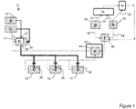
- Figure 1 shows a diagrammatic representation of a fuel system 10 according to the present disclosure integrated with multiple engines 12.
- the engines 12 may form part of a vehicle, for example an aircraft or marine vessel.
- the example in Figure 1 shows three engines, the fuel system of the present disclosure is equally applicable to single or multi-engine systems.
- the system 10 comprises a fuel blender 14 in fluid communication with a source of a first fuel composition, shown as a first tank 18 for storage of the first fuel composition and a source of a second fuel composition, shown as a second tank 22 for storage of the second fuel composition.
- the first tank 18 and second tank 22 are fluidly isolated from one another.
- the blender 14 is operable to mix the first fuel composition and second fuel composition to produce a resultant fuel composition.
- the fuel blender 14 has a first inlet 32 in fluid communication with the first tank 18, and a second inlet 34 in fluid communication with the second tank 22, and is thus configured to receive the first fuel composition and the second fuel composition.
- the fuel blender 14 has a single inlet which is in fluid communication with both the first tank 18 and the second tank 22.
- the term "tank" is taken to mean a single vessel, or one of a network of fluidly connected vessels, where each network is fluidly isolated from the other networks.
- the blender 14 is configured to output the resultant fuel composition comprising the received fuel compositions via at least one outlet 36, the at least one outlet 36 being in fluid communication with an engine fuel injection device 38 on each engine 12.
- the fuel injection device 38 may be any type of fuel injector, for example a fuel nozzle, airspray injector, or plain orifice.
- the fuel injection device 38 may comprise one fuel injector, or a plurality of fuel injectors. Although in Figure 1 only one fuel injector 38 is shown, each engine 12 may be fitted with a number of fuel injectors 38, each in fluid communication with the fuel blender 14.
- the fuel blender 14 comprises a regulator 40 for controlling the percentage of first and second fuel composition which are blended together.
- the regulator 40 is provided separately to, and upstream from, the fuel blender 14.
- inlets 32, 34 would be provided in the regulator 40, and the fuel blender 14 would have at least one inlet which would be in fluid communication with an outlet of the regulator 40.
- the regulator 40 is responsive to a signal from a control unit 42 which defines the percentage of first and second fuel composition to be blended together.
- the control unit 42 comprises a blending ratio calculator 44 configured to calculate the required resultant fuel composition as a function of desired soot emission index determined by a soot requirement generator 46, where the soot requirement generator 46 is operable to communicate the value of desired soot emission index to the blending ratio calculator 44.
- the fuel system 10 also comprises a first sensor array 48 configured to produce signals 50 indicative of ambient temperature, ambient pressure, ambient humidity and/or vapour trail optical depth.
- the soot requirement generator 46 is in communication with the first sensor array 48 to receive the one or more measured values.
- the fuel system 10 optionally comprises a second sensor array 52 configured to produce a signal 54 indicative of instantaneous actual soot emission index.
- the second sensor array 52 may be mounted appropriately such that each sensor in the array has a sensing region or field of view which includes any part of the engine's internal airflow after the point of combustion, and/or the engine exhaust duct, and/or or the region into which exhaust from the engine is directed, and/or the region where vapour trails form or may form.
- the soot requirement generator 46 is in communication with the second sensor array 52 to receive a value for instantaneous measured actual values of soot emission index generated by the engine(s) 12, which is communicated to the control unit 42 and blending ratio calculator 44.
- the blending ratio calculator 44 may be in direct communication with the second sensor array 52 to receive the signal 54 indicative of instantaneous measured actual values of soot emission index generated by the engine(s) 12.
- the soot requirement generator 46 is configured to calculate the desired soot emission index as a function of one or more measured values of ambient temperature, ambient pressure, ambient humidity and/or vapour trail optical depth.
- the soot requirement generator 46 may comprise a model and/or algorithm for direct calculation of the desired soot emission index.
- the desired soot emission index is derived from a look up table or database in dependence upon one or more of the first and second fuel composition, combustion characteristics of the engine 12 and engine operating point.
- the engine operating point is defined by a collection of parameters including ambient temperature, ambient pressure, ambient humidity and for example one or more of fuel-flow rate, temperatures and pressures of the gas flow at various parts of the engine, thrust produced by the engine, and other parameters indicative of the state of the engine.
- the soot requirement generator may be configured to receive signals indicative of the engine stat of the engine(s).
- the blending ratio calculator 44 may be configured to calculate the required resultant fuel composition in dependence upon at least the instantaneous actual soot emission index. That is to say, the blending ratio calculator 44 may be configured to use a value of actual soot emission index being generated by the engine(s) 12 in determining whether or not the relative constituent parts of the resultant fuel composition (e.g. the first and second fuel compositions) should be adjusted relative to one another, in an iterative process as required, to thereby reduce the error between the desired soot emission index and the actual soot emission index.
- the blending ratio calculator 44 may be configured to calculate the required resultant fuel composition in dependence upon at least the instantaneous actual soot emission index. That is to say, the blending ratio calculator 44 may be configured to use a value of actual soot emission index being generated by the engine(s) 12 in determining whether or not the relative constituent parts of the resultant fuel composition (e.g. the first and second fuel compositions) should be adjusted relative to one another, in an iterative process as required
- the blending ratio calculator 44 may be configured to calculate the required resultant fuel composition in dependence upon one or more of the composition of the first fuel composition and second fuel composition.
- the calculation of the resultant fuel composition by the blending ration calculator 44 may also depend on parameters indicative of the state of the engine (such as one or more of fuel-flow rate, temperatures and pressures of the gas flow at various parts of the engine, thrust produced by the engine and the speed of the engine through the ambient air).
- the blending ratio calculator 44 may be configured to calculate the required resultant fuel composition in dependence upon the aromatic and/or other non-paraffinic content (for example as expressed as percentage by mass or alternatively percentage by volume) of the first fuel composition and of the second fuel composition.
- the first and second fuel compositions may be determined by direct analysis or derived from a database or data record.
- the system 10 further comprises a vapour trail modelling tool 58 configured to first determine ambient air conditions in dependence upon actual measured values of ambient air conditions, and then to determine the likelihood of vapour trail formation and/or vapour trail persistence based upon one or more of the parameters defining the engine operating point and the determined ambient air conditions.
- the vapour trail modelling tool 58 may be further configured to communicate to the control unit 42 a signal indicative of the determined likelihood of vapour trail formation and/or persistence.
- the control unit 40 may determine which of a default fuel composition and a composition which may enable the optical depth of the vapour trail to be reduced is employed. This determination may be based on the determined likelihood of contrail formation and/or persistence, and taking into account an operational policy specifying the conditions under which vapour trail optical-depth modification should be attempted.
- the comparator 56 may also be configured to compare output from the vapour trail modelling tool 58 with an instantaneous actual vapour trail observation signal 54 to determine the effect of the resultant fuel composition on vapour trail optical depth.
- FIG. 2 An alternative example is shown in Figure 2 .
- This example is essentially the same as the Figure 1 example, except that each engine 12 is in fluid communication with a dedicated fuel blender 14, and each fuel blender 14 is in fluid communication with the first tank 18 and second tank 22.
- each fuel injector 38 has its own dedicated fuel blender 14 and/or regulator 40.
- the system 10 is thus configured to provide fuel to the engine(s) 12 during a period of operation of the engine(s) 12.
- the soot requirement generator 46 determines a value of optimal soot emission index which would generate optimal vapour trail optical depth for a given ambient condition. From this it determines a value of desired soot emission index which is employed to calculate or otherwise determine the resultant fuel composition which, when supplied to the engine(s) 12, is intended to achieve the desired soot emission index in the exhaust plume of the engine.
- the soot requirement generator 46 calculates or otherwise determines the desired soot emission index as a function of one or more measured values of ambient temperature, ambient pressure, ambient humidity and/or vapour trail optical depth. Hence the system 10 is configured to adapt to different ambient conditions, where different ambient conditions will result in vapour trails having different optical depths for the same soot emission index.
- optical soot emission index is the soot emission index which, if realised in practice under the prevailing ambient conditions, would lead to a minimisation of optical depth of a young contrail, and hence a minimisation of the young contrail's climate warming impact.
- the "optimal" soot emission index may correspond to the minimum achievable soot emission index given the available fuels and any constraints that may place limits on the blending ratios that may be employed.
- the "optimal" soot emission index may be higher than the minimum achievable soot emission index.
- the “desired" soot emission index may be identical to the optimal soot emission index.
- the "desired" soot emission index would represent an alternative target which lies within the range that can be achieved by the system.
- the blending ratio calculator 44 associated with the control unit 42 calculates the required resultant fuel composition as a function of desired soot emission index determined by the soot requirement generator 46 which communicates the value of desired soot emission index to the blending ratio calculator 44.
- the regulator 40 responds to a signal from the control unit 42 which defines the percentage of first and second fuel composition to be blended together.
- the regulator 40 controls the defined percentages of first fuel composition and second fuel composition which are taken from the first and second tanks 18,22 respectively, and delivered to the blender 14.
- the blender 14 is configured to mix the first fuel composition and second fuel composition to produce the resultant fuel composition.
- the resultant fuel composition is then delivered to the engine(s)12.
- the resultant fuel composition may comprise any proportion of first fuel composition and second fuel composition in the range from 0% to 100%.
- the resultant fuel composition may comprise x% of the first fuel composition and (100-x)% of the second fuel composition, where x has a value anywhere in the range from 0 to 100.
- the resultant fuel composition may comprise 0% of the first fuel composition and 100% of the second fuel composition.
- the resultant fuel composition may comprise 100% of the first fuel composition and 0% of the second fuel composition.
- x may have a value of greater than 0 and less than 100.
- the vapour trail modelling tool 58 operates to first determine ambient air conditions in dependence upon actual measured values of ambient air conditions, and then to determine the likelihood of vapour trail formation and/or vapour trail persistence based upon one or more of the parameters defining the engine operating point and the determined ambient air conditions.
- the vapour trail modelling tool 58 may be further configured to communicate to the control unit 42 a signal indicative of the determined likelihood of vapour trail formation and/or persistence.
- the comparator 56 compares output from the vapour trail modelling tool 58 with an instantaneous actual vapour trail observation and determines the effect of the resultant fuel composition on vapour trail optical depth. The result of the comparison is fed back to the soot requirement generator 46, and thus the blending ratio calculator 44, and further adjustments to the resultant fuel composition made as required to achieve the desired soot emission index and hence desired vapour trail optical depth.
- soot requirement generator receives a value for instantaneous measured actual values of soot emission index 54 generated by the engine from the sensing means 52, compares the actual value of soot emission index to a desired value of soot emission index, and determines action required to achieve or approach the desired soot emission index.
- the blending ratio calculator 44 may be in direct communication with the second sensor array 52 to receive the signal 54 indicative of instantaneous measured actual values of soot emission index generated by the engine(s) 12.
- the system may further comprise a means of determining by measurement and/or calculation whether or not vapour trail formation (irrespective of subsequent persistence) is likely under current ambient conditions and engine operating point.
- a means of determining by measurement and/or calculation whether or not vapour trail formation (irrespective of subsequent persistence) is likely under current ambient conditions and engine operating point.
- the Schmidt-Appleman criterion may be applied and coupled with an assumption of a linear or approximately linear mixing trajectory in the space defined by temperature and H 2 O partial pressure.
- the first fuel composition may have an aromatic and/or other non-paraffinic content substantially higher than that of the second fuel composition.
- the first fuel composition is kerosene.
- the second fuel composition is a biofuel.
- the second fuel composition may be a low-soot-producing (LSP) or alternatively a low-sulphur, low-soot-producing (LSLSP) fuel.
- LSP low-soot-producing
- LSLSP low-sulphur, low-soot-producing
- the second fuel may be a blend of several such LSP and/or LSLSP fuels whose physical and chemical properties make it suitable for use in an engine in combination with the first fuel composition, for example as an aviation fuel when blended with conventional kerosene.
- Examples include (but are not limited to) coal-to-liquids (CTL), gas-to-liquids (GTL), biomass-to-liquids (BTL), synthetic paraffinic kerosene (SPK), hydrotreated renewable jet-fuel (HRJ), alcohol-to-jet, and Hydroprocessed Esters and Fatty Acids (HEFA).
- CTL coal-to-liquids
- GTL gas-to-liquids
- BTL biomass-to-liquids
- SPK synthetic paraffinic kerosene
- HRJ hydrotreated renewable jet-fuel
- alcohol-to-jet Hydroprocessed Esters and Fatty Acids
- the system 10 is operable to blend fuel, or to simply deliver one of the stored fuel compositions. That is to say it may optionally be employed or not employed according to policy decision. For example in the absence of vapour trail formation, one may choose to use only one of the first or second fuel compositions, and hence the resultant fuel composition will simply be the first or second fuel composition. For example 100% kerosene may be delivered to the engines 12, rather than a blend of kerosene and biofuel. Alternatively where the ambient conditions are such that vapour trails form but do not persist (i.e. in ambient air not super-saturated with respect to ice), the system could be operated or not operated, depending on the extent to which the occurrence of temporary vapour trails is considered desirable or not.
- the system may be operated to produce a soot emission index that will reduce the incidence of cloud formation or enhancement in the said nearby region.
- vapour trails form and persist, it is envisaged that the system would operate so as to reduce the optical depth of the "young" vapour trail.
- the system herein described is thus advantageous since it enables control over vapour trail optical depth by selectively blending together on demand (for example) a conventional fuel together with a fuel characterised by low levels of aromatic and/or other non-paraffinic content for use in an engine to optimise soot emission index in the products of combustion from the engine.
- a conventional fuel together with a fuel characterised by low levels of aromatic and/or other non-paraffinic content for use in an engine to optimise soot emission index in the products of combustion from the engine.
- one of the fuels (for example a fuel characterised by low levels of aromatic and/or other non-paraffinic content) need only be used during part of the operation of the engine. This is of particular benefit as such fuels tend to be more expensive to produce.
- the system of the present invention enables reduction of the optical depth, and hence the climate warming impact, of vapour trails in a cost effective manner.
- the fuel system of the present disclosure has little weight penalty, little power requirements in usage, and maximises the climate benefits of a given volume of, for example, biofuel.
- the aircraft need not avoid unfavourable altitudes at which vapour trails would be unavoidable for an aircraft burning conventional fuel (e.g. kerosene), and hence will tend to travel less distance, and tend to travel at favourable altitudes, thereby minimising its overall fuel consumption. Furthermore such a system avoids any loss of airspace capacity because it reduces the climate warming impact associated with aviation induced cloudiness formed whilst cruising within ice-supersaturated regions.
- the fuel system of the present disclosure enables the aircraft to follow an optimal cruise-climb trajectory, whilst minimising the resulting vapour-trail related climate impact.
- the fuel system of the present disclosure maximises climate benefit for a given expenditure on alternative fuels.
- the system of the present disclosure will enable vehicles (aircraft, marine etc) to control vapour trail optical depth, thus increasing their envelope of operation.
Landscapes
- Engineering & Computer Science (AREA)
- Chemical & Material Sciences (AREA)
- Combustion & Propulsion (AREA)
- Mechanical Engineering (AREA)
- General Engineering & Computer Science (AREA)
- Physics & Mathematics (AREA)
- General Physics & Mathematics (AREA)
- Automation & Control Theory (AREA)
- Combined Controls Of Internal Combustion Engines (AREA)
- Output Control And Ontrol Of Special Type Engine (AREA)
- Fuel-Injection Apparatus (AREA)
Claims (13)
- Kraftstoffsystem (10), umfassend:einen Kraftstoffmischer (14) in Fluidkommunikation mit einer Quelle einer ersten Kraftstoffzusammensetzung und einer Quelle einer zweiten Kraftstoffzusammensetzung über zumindest einen Einlass (32, 34), wobei der Kraftstoffmischer konfiguriert ist, um die erste Kraftstoffzusammensetzung und die zweite Kraftstoffzusammensetzung zu mischen;einen Regulator (40) zum Steuern des Prozentanteils an erster und zweiter Kraftstoffzusammensetzung, die miteinander vermischt werden; undeine Steuereinheit (42); undein Kondensstreifenmodellierwerkzeug (58);wobei der Kraftstoffmischer (14) bedienbar ist, um die erste Kraftstoffzusammensetzung und die zweite Kraftstoffzusammensetzung über den zumindest einen Einlass zu empfangen und eine sich ergebende Kraftstoffzusammensetzung, die die empfangenen Kraftstoffzusammensetzungen umfasst, über zumindest einen Auslass (36) auszugeben;wobei der zumindest eine Auslass (36) in Fluidkommunikation mit einer Triebwerkskraftstoffeinspritzvorrichtung (38) ist;wobei der Regulator (40) auf ein Signal von der Steuereinheit (42) reagiert, das den Prozentanteil der miteinander zu vermischenden ersten und zweiten Kraftstoffzusammensetzung definiert;wobei die Steuereinheit (42) einen Mischverhältnisrechner (44) umfasst, der konfiguriert ist, um eine erforderliche sich ergebende Kraftstoffzusammensetzung abhängig von dem gewünschten Rußemissionsindex zu berechnen, wobei der gewünschte Rußemissionsindex durch einen Rußerfordernisgenerator (46) bestimmt wird, der bedienbar ist, um den gewünschten Wert des Rußemissionsindex an den Mischverhältnisrechner zu kommunizieren; undwobei das Kondensstreifenmodellierwerkzeug (58) konfiguriert ist, um zuerst Umgebungsluftbedingungen in Abhängigkeit von tatsächlichen gemessenen Werten von Umgebungsluftbedingungen zu bestimmen und um dann die Wahrscheinlichkeit von Kondensstreifenbildung und/oder Kondensstreifenbeständigkeit basierend auf Triebwerksbetriebspunkt und Umgebungsluftbedingungen zu bestimmen.
- Kraftstoffsystem nach Anspruch 1, wobei die Quelle der ersten Kraftstoffzusammensetzung ein erster Tank (18) zur Aufbewahrung der ersten Kraftstoffzusammensetzung ist; wobei die Quelle der zweiten Kraftstoffzusammensetzung ein zweiter Tank (22) zur Aufbewahrung der zweiten Kraftstoffzusammensetzung ist; wobei der erste Tank und der zweite Tank fluidisch voneinander isoliert sind.
- Kraftstoffsystem nach Anspruch 1 oder 2, wobei der Mischverhältnisrechner (44) konfiguriert ist, um die sich ergebende Kraftstoffzusammensetzung einzustellen, um in Richtung des gewünschten Rußemissionsindex zu iterieren.
- Kraftstoffsystem nach Anspruch 3, ferner umfassend einen Sensor (48, 52), der konfiguriert ist, um ein Signal zu erzeugen, das den aktuellen tatsächlichen Rußemissionsindex angibt, wobei der Mischverhältnisrechner (44) konfiguriert ist, um die erforderliche sich ergebende Kraftstoffzusammensetzung in Abhängigkeit von dem Unterschied zwischen dem gewünschten Rußemissionsindex und dem aktuellen tatsächlichen Rußemissionsindex zu berechnen.
- Kraftstoffsystem nach Anspruch 4, wobei der Rußerfordernisgenerator (46) einen Wert des gewünschten Rußemissionsindex bestimmt, der optimale optische Kondensstreifentiefe für gegebene Umgebungsbedingungen und gegebenen Triebwerksbetriebspunkt erzeugen würde.
- Kraftstoffsystem nach Anspruch 5, wobei der Rußerfordernisgenerator (46) ein Modell und/oder einen Algorithmus für direkte Berechnung des gewünschten Rußemissionsindex umfasst.
- Kraftstoffsystem nach Anspruch 6, wobei der Rußemissionsindex abgeleitet ist von einer Nachschlagetabelle oder Datenbank in Abhängigkeit von einem oder mehreren von der ersten und der zweiten Kraftstoffzusammensetzung, Verbrennungseigenschaften des Triebwerks und des Triebwerksbetriebspunktes definiert durch eine Sammlung von Parametern, die Umgebungstemperatur, Umgebungsdruck, Umgebungsluftfeuchtigkeit umfassen, und Parametern, die den Zustand des Triebwerks angeben.
- Kraftstoffsystem nach Anspruch 6, wobei der Rußerfordernisgenerator (46) konfiguriert ist, um den gewünschten Rußemissionsindex abhängig von einem oder mehreren gemessenen Werten von Umgebungstemperatur, Umgebungsdruck, Umgebungsluftfeuchtigkeit und/oder optischer Kondensstreifentiefe zu berechnen, und wobei optional der Rußerfordernisgenerator (46) in Kommunikation mit Sensormitteln ist, um den einen oder die mehreren gemessenen Werte zu empfangen.
- Kraftstoffsystem nach einem vorhergehenden Anspruch, ferner umfassend einen Vergleicher (56) zum Vergleichen von Ausgabe von dem Kondensstreifenmodellierwerkzeug (58) mit einer aktuellen tatsächlichen Kondensstreifenbeobachtung, um die Wirkung der sich ergebenden Kraftstoffzusammensetzung auf die optische Kondensstreifentiefe zu bestimmen.
- Triebwerk, umfassend ein Kraftstoffsystem (10) nach einem der Ansprüche 1 bis 9.
- Fahrzeug, umfassend ein Kraftstoffsystem (10) nach einem der Ansprüche 1 bis 9.
- Luftfahrzeug, umfassend ein Kraftstoffsystem (10) nach einem der Ansprüche 1 bis 9.
- Wasserfahrzeug, umfassend ein Kraftstoffsystem (10) nach einem der Ansprüche 1 bis 9.
Priority Applications (1)
| Application Number | Priority Date | Filing Date | Title |
|---|---|---|---|
| EP20183367.0A EP3875740B1 (de) | 2012-06-22 | 2013-05-17 | Bereitstellung von kraftstoff |
Applications Claiming Priority (1)
| Application Number | Priority Date | Filing Date | Title |
|---|---|---|---|
| GBGB1211058.1A GB201211058D0 (en) | 2012-06-22 | 2012-06-22 | Fuel system |
Related Child Applications (1)
| Application Number | Title | Priority Date | Filing Date |
|---|---|---|---|
| EP20183367.0A Division EP3875740B1 (de) | 2012-06-22 | 2013-05-17 | Bereitstellung von kraftstoff |
Publications (3)
| Publication Number | Publication Date |
|---|---|
| EP2677138A2 EP2677138A2 (de) | 2013-12-25 |
| EP2677138A3 EP2677138A3 (de) | 2018-01-24 |
| EP2677138B1 true EP2677138B1 (de) | 2020-07-22 |
Family
ID=46641326
Family Applications (2)
| Application Number | Title | Priority Date | Filing Date |
|---|---|---|---|
| EP20183367.0A Active EP3875740B1 (de) | 2012-06-22 | 2013-05-17 | Bereitstellung von kraftstoff |
| EP13168161.1A Active EP2677138B1 (de) | 2012-06-22 | 2013-05-17 | Kraftstoffsystem |
Family Applications Before (1)
| Application Number | Title | Priority Date | Filing Date |
|---|---|---|---|
| EP20183367.0A Active EP3875740B1 (de) | 2012-06-22 | 2013-05-17 | Bereitstellung von kraftstoff |
Country Status (3)
| Country | Link |
|---|---|
| US (1) | US9146566B2 (de) |
| EP (2) | EP3875740B1 (de) |
| GB (1) | GB201211058D0 (de) |
Families Citing this family (21)
| Publication number | Priority date | Publication date | Assignee | Title |
|---|---|---|---|---|
| US10156192B2 (en) * | 2012-10-05 | 2018-12-18 | General Electric Company | Gas turbine engine with a multiple fuel delivery system |
| GB201317732D0 (en) * | 2013-10-08 | 2013-11-20 | Rolls Royce Plc | Aircraft engine fuel system |
| GB201317731D0 (en) * | 2013-10-08 | 2013-11-20 | Rolls Royce Plc | Fuel delivery system |
| GB201319997D0 (en) | 2013-11-13 | 2013-12-25 | Rolls Royce Plc | Engine fuel delivery system |
| US20150266589A1 (en) * | 2014-03-24 | 2015-09-24 | Honeywell International Inc. | Aircraft systems and methods with green fuel tanks |
| GB2524775B (en) * | 2014-04-02 | 2017-11-15 | Rolls Royce Plc | Aircraft vapour trail control system |
| GB201420989D0 (en) * | 2014-11-26 | 2015-01-07 | Rolls Royce Plc | Aircraft engine fuel system |
| FR3075932B1 (fr) * | 2017-12-21 | 2020-01-03 | Ge Energy Products France Snc | Procede d'optimisation de la limitation des emissions de poussieres pour les turbines a gaz alimentees au fioul lourd. |
| US11193420B2 (en) * | 2018-11-16 | 2021-12-07 | United Technologies Corporation | System and method for monitoring fuel additives |
| EP3875742A1 (de) * | 2020-03-04 | 2021-09-08 | Rolls-Royce plc | Gestufte verbrennung |
| GB202112642D0 (en) | 2021-09-06 | 2021-10-20 | Rolls Royce Plc | Controlling soot |
| GB202112641D0 (en) * | 2021-09-06 | 2021-10-20 | Rolls Royce Plc | Controlling soot |
| US11780597B2 (en) * | 2021-12-21 | 2023-10-10 | Rolls-Royce Plc | Aircraft propulsion |
| GB2616824A (en) | 2021-12-21 | 2023-09-27 | Rolls Royce Plc | Aircraft fuel management |
| GB2616823A (en) | 2021-12-21 | 2023-09-27 | Rolls Royce Plc | Aircraft fuel management |
| EP4532916A1 (de) * | 2022-05-27 | 2025-04-09 | Hyliion Inc. | Multikraftstoffsystem und verfahren zur verwaltung der leistung |
| GB202219390D0 (en) * | 2022-12-21 | 2023-02-01 | Rolls Royce Plc | Gas turbine operation |
| GB202219391D0 (en) | 2022-12-21 | 2023-02-01 | Rolls Royce Plc | Fuel oil heat exchange |
| GB202408234D0 (en) * | 2024-06-10 | 2024-07-24 | Rolls Royce Plc | Aircraft emissions |
| US12565861B1 (en) * | 2024-08-28 | 2026-03-03 | Air Products And Chemicals, Inc. | Apparatus and method to control supplying fuel to a gas turbine system |
| FR3166732A1 (fr) * | 2024-09-20 | 2026-03-27 | Thales | Procédé et dispositif d’allocation de carburant d’aviation durable à une pluralité de vols |
Family Cites Families (23)
| Publication number | Priority date | Publication date | Assignee | Title |
|---|---|---|---|---|
| US3517505A (en) | 1962-11-13 | 1970-06-30 | Us Air Force | Method and apparatus for suppressing contrails |
| US3289409A (en) | 1964-07-13 | 1966-12-06 | Phillips Petroleum Co | Hiding condensation trails from high altitude aircraft |
| US3517512A (en) | 1965-02-02 | 1970-06-30 | Us Air Force | Apparatus for suppressing contrails |
| GB2058211B (en) | 1979-09-13 | 1983-03-09 | Showa Line Ltd | Diesel engine fuel-mixing system |
| DE3039039A1 (de) | 1980-10-16 | 1982-05-13 | Gustav F. 2800 Bremen Holtz | Verfahren und anlage zum betreiben eines verbrennungsmotors an bord von schiffen |
| JPS61149566A (ja) | 1984-12-24 | 1986-07-08 | Hitachi Zosen Corp | 船舶用燃料船内ブレンド方法 |
| US4766725A (en) | 1985-12-24 | 1988-08-30 | Scipar, Inc. | Method of suppressing formation of contrails and solution therefor |
| US5005355A (en) | 1988-08-24 | 1991-04-09 | Scipar, Inc. | Method of suppressing formation of contrails and solution therefor |
| US5285256A (en) | 1992-07-28 | 1994-02-08 | Ophir Corporation | Rear-looking apparatus and method for detecting contrails |
| JP3174649B2 (ja) * | 1992-11-10 | 2001-06-11 | 三菱重工業株式会社 | ガスタービン燃焼器 |
| US5546183A (en) * | 1994-10-12 | 1996-08-13 | Northrop Grumman Corporation | Lidar droplet size monitor for in-flight measurement of aircraft engine exhaust contrails, droplets and aerosols |
| US5469830A (en) | 1995-02-24 | 1995-11-28 | The Cessna Aircraft Company | Fuel blending system method and apparatus |
| US5911210A (en) * | 1997-10-03 | 1999-06-15 | Cooper Cameron Corporation | Method and apparatus for supplying fuel to an internal combustion engine |
| DE102004050602B4 (de) * | 2004-10-15 | 2010-05-20 | Kangler, Wolfram, Dipl.-Phys. | Verfahren zur Verifikation zumindest eines vorgegebenen Kraftstoffmischungsverhältnisses |
| WO2007061903A1 (en) | 2005-11-17 | 2007-05-31 | Cps Biofuels, Inc. | Alternative fuel and fuel additive compositions |
| US8006677B2 (en) | 2006-02-02 | 2011-08-30 | Immixt, LLC | Fuel control system and associated method |
| GB0608859D0 (en) | 2006-05-05 | 2006-06-14 | Rolls Royce Plc | A gas turbine engine |
| FI119319B (fi) * | 2006-11-30 | 2008-10-15 | Waertsilae Finland Oy | Vesialuksen koneisto ja menetelmä pakokaasupäästöjen kontrolloimiseksi vesialuksessa |
| GB0710153D0 (en) | 2007-05-26 | 2007-07-04 | Rolls Royce Plc | Method and apparatus for suppressing aeroengine contrails |
| GB0710162D0 (en) | 2007-05-26 | 2007-07-04 | Rolls Royce Plc | Method and apparatus for suppressing aeroengine contrails |
| US9080513B2 (en) * | 2007-10-31 | 2015-07-14 | General Electric Company | Method and apparatus for combusting syngas within a combustor |
| US20100122519A1 (en) * | 2008-11-14 | 2010-05-20 | Alan Epstein | Ultra-low sulfur fuel and method for reduced contrail formation |
| DE102009005356A1 (de) * | 2009-01-16 | 2010-07-22 | Voith Patent Gmbh | Verfahren und Vorrichtung zum Betrieb eines Dieselmotors mit einem Mischkraftstoff |
-
2012
- 2012-06-22 GB GBGB1211058.1A patent/GB201211058D0/en not_active Ceased
-
2013
- 2013-05-17 EP EP20183367.0A patent/EP3875740B1/de active Active
- 2013-05-17 US US13/896,766 patent/US9146566B2/en active Active
- 2013-05-17 EP EP13168161.1A patent/EP2677138B1/de active Active
Non-Patent Citations (1)
| Title |
|---|
| None * |
Also Published As
| Publication number | Publication date |
|---|---|
| EP2677138A3 (de) | 2018-01-24 |
| EP3875740B1 (de) | 2023-11-15 |
| EP2677138A2 (de) | 2013-12-25 |
| US20130340324A1 (en) | 2013-12-26 |
| GB201211058D0 (en) | 2012-08-01 |
| US9146566B2 (en) | 2015-09-29 |
| EP3875740A1 (de) | 2021-09-08 |
Similar Documents
| Publication | Publication Date | Title |
|---|---|---|
| EP2677138B1 (de) | Kraftstoffsystem | |
| US9518965B2 (en) | Fuel system | |
| EP2860374B1 (de) | Brennstoffzuführsystem | |
| US11821373B2 (en) | Staged combustion | |
| EP2860375B1 (de) | Kraftstoffsystem für Flugzeugtriebwerke | |
| US9399521B2 (en) | Aircraft vapour trail control system | |
| EP2677139B1 (de) | Brennstoffzufuhrsystem | |
| US4903478A (en) | Dual manifold fuel system | |
| US9440746B2 (en) | Aircraft vapour trail control system | |
| US5036657A (en) | Dual manifold fuel system | |
| US9109545B2 (en) | Systems and methods for controlling exhaust gas recirculation composition | |
| EP3026241A1 (de) | Kraftstoffsystem für flugzeugtriebwerke | |
| US20110247315A1 (en) | Flexible fuel system | |
| US12241409B2 (en) | Aircraft propulsion system | |
| EP3327280B1 (de) | Motorvorrichtung | |
| CN116816560A (zh) | 一种航空活塞机面对突变环境失稳判定及控制方法 |
Legal Events
| Date | Code | Title | Description |
|---|---|---|---|
| PUAI | Public reference made under article 153(3) epc to a published international application that has entered the european phase |
Free format text: ORIGINAL CODE: 0009012 |
|
| AK | Designated contracting states |
Kind code of ref document: A2 Designated state(s): AL AT BE BG CH CY CZ DE DK EE ES FI FR GB GR HR HU IE IS IT LI LT LU LV MC MK MT NL NO PL PT RO RS SE SI SK SM TR |
|
| AX | Request for extension of the european patent |
Extension state: BA ME |
|
| RAP1 | Party data changed (applicant data changed or rights of an application transferred) |
Owner name: ROLLS-ROYCE PLC |
|
| PUAL | Search report despatched |
Free format text: ORIGINAL CODE: 0009013 |
|
| AK | Designated contracting states |
Kind code of ref document: A3 Designated state(s): AL AT BE BG CH CY CZ DE DK EE ES FI FR GB GR HR HU IE IS IT LI LT LU LV MC MK MT NL NO PL PT RO RS SE SI SK SM TR |
|
| AX | Request for extension of the european patent |
Extension state: BA ME |
|
| RIC1 | Information provided on ipc code assigned before grant |
Ipc: F02C 9/40 20060101ALI20171219BHEP Ipc: F02C 3/30 20060101AFI20171219BHEP |
|
| STAA | Information on the status of an ep patent application or granted ep patent |
Free format text: STATUS: REQUEST FOR EXAMINATION WAS MADE |
|
| 17P | Request for examination filed |
Effective date: 20180723 |
|
| RBV | Designated contracting states (corrected) |
Designated state(s): AL AT BE BG CH CY CZ DE DK EE ES FI FR GB GR HR HU IE IS IT LI LT LU LV MC MK MT NL NO PL PT RO RS SE SI SK SM TR |
|
| STAA | Information on the status of an ep patent application or granted ep patent |
Free format text: STATUS: EXAMINATION IS IN PROGRESS |
|
| 17Q | First examination report despatched |
Effective date: 20190403 |
|
| GRAP | Despatch of communication of intention to grant a patent |
Free format text: ORIGINAL CODE: EPIDOSNIGR1 |
|
| STAA | Information on the status of an ep patent application or granted ep patent |
Free format text: STATUS: GRANT OF PATENT IS INTENDED |
|
| RAP1 | Party data changed (applicant data changed or rights of an application transferred) |
Owner name: ROLLS-ROYCE PLC |
|
| INTG | Intention to grant announced |
Effective date: 20200219 |
|
| GRAS | Grant fee paid |
Free format text: ORIGINAL CODE: EPIDOSNIGR3 |
|
| GRAA | (expected) grant |
Free format text: ORIGINAL CODE: 0009210 |
|
| STAA | Information on the status of an ep patent application or granted ep patent |
Free format text: STATUS: THE PATENT HAS BEEN GRANTED |
|
| AK | Designated contracting states |
Kind code of ref document: B1 Designated state(s): AL AT BE BG CH CY CZ DE DK EE ES FI FR GB GR HR HU IE IS IT LI LT LU LV MC MK MT NL NO PL PT RO RS SE SI SK SM TR |
|
| REG | Reference to a national code |
Ref country code: GB Ref legal event code: FG4D |
|
| REG | Reference to a national code |
Ref country code: CH Ref legal event code: EP |
|
| REG | Reference to a national code |
Ref country code: DE Ref legal event code: R096 Ref document number: 602013070853 Country of ref document: DE |
|
| REG | Reference to a national code |
Ref country code: AT Ref legal event code: REF Ref document number: 1293596 Country of ref document: AT Kind code of ref document: T Effective date: 20200815 |
|
| REG | Reference to a national code |
Ref country code: IE Ref legal event code: FG4D |
|
| REG | Reference to a national code |
Ref country code: LT Ref legal event code: MG4D |
|
| REG | Reference to a national code |
Ref country code: AT Ref legal event code: MK05 Ref document number: 1293596 Country of ref document: AT Kind code of ref document: T Effective date: 20200722 |
|
| PG25 | Lapsed in a contracting state [announced via postgrant information from national office to epo] |
Ref country code: ES Free format text: LAPSE BECAUSE OF FAILURE TO SUBMIT A TRANSLATION OF THE DESCRIPTION OR TO PAY THE FEE WITHIN THE PRESCRIBED TIME-LIMIT Effective date: 20200722 Ref country code: SE Free format text: LAPSE BECAUSE OF FAILURE TO SUBMIT A TRANSLATION OF THE DESCRIPTION OR TO PAY THE FEE WITHIN THE PRESCRIBED TIME-LIMIT Effective date: 20200722 Ref country code: LT Free format text: LAPSE BECAUSE OF FAILURE TO SUBMIT A TRANSLATION OF THE DESCRIPTION OR TO PAY THE FEE WITHIN THE PRESCRIBED TIME-LIMIT Effective date: 20200722 Ref country code: HR Free format text: LAPSE BECAUSE OF FAILURE TO SUBMIT A TRANSLATION OF THE DESCRIPTION OR TO PAY THE FEE WITHIN THE PRESCRIBED TIME-LIMIT Effective date: 20200722 Ref country code: PT Free format text: LAPSE BECAUSE OF FAILURE TO SUBMIT A TRANSLATION OF THE DESCRIPTION OR TO PAY THE FEE WITHIN THE PRESCRIBED TIME-LIMIT Effective date: 20201123 Ref country code: FI Free format text: LAPSE BECAUSE OF FAILURE TO SUBMIT A TRANSLATION OF THE DESCRIPTION OR TO PAY THE FEE WITHIN THE PRESCRIBED TIME-LIMIT Effective date: 20200722 Ref country code: NO Free format text: LAPSE BECAUSE OF FAILURE TO SUBMIT A TRANSLATION OF THE DESCRIPTION OR TO PAY THE FEE WITHIN THE PRESCRIBED TIME-LIMIT Effective date: 20201022 Ref country code: GR Free format text: LAPSE BECAUSE OF FAILURE TO SUBMIT A TRANSLATION OF THE DESCRIPTION OR TO PAY THE FEE WITHIN THE PRESCRIBED TIME-LIMIT Effective date: 20201023 Ref country code: BG Free format text: LAPSE BECAUSE OF FAILURE TO SUBMIT A TRANSLATION OF THE DESCRIPTION OR TO PAY THE FEE WITHIN THE PRESCRIBED TIME-LIMIT Effective date: 20201022 Ref country code: AT Free format text: LAPSE BECAUSE OF FAILURE TO SUBMIT A TRANSLATION OF THE DESCRIPTION OR TO PAY THE FEE WITHIN THE PRESCRIBED TIME-LIMIT Effective date: 20200722 |
|
| PG25 | Lapsed in a contracting state [announced via postgrant information from national office to epo] |
Ref country code: RS Free format text: LAPSE BECAUSE OF FAILURE TO SUBMIT A TRANSLATION OF THE DESCRIPTION OR TO PAY THE FEE WITHIN THE PRESCRIBED TIME-LIMIT Effective date: 20200722 Ref country code: PL Free format text: LAPSE BECAUSE OF FAILURE TO SUBMIT A TRANSLATION OF THE DESCRIPTION OR TO PAY THE FEE WITHIN THE PRESCRIBED TIME-LIMIT Effective date: 20200722 Ref country code: LV Free format text: LAPSE BECAUSE OF FAILURE TO SUBMIT A TRANSLATION OF THE DESCRIPTION OR TO PAY THE FEE WITHIN THE PRESCRIBED TIME-LIMIT Effective date: 20200722 Ref country code: IS Free format text: LAPSE BECAUSE OF FAILURE TO SUBMIT A TRANSLATION OF THE DESCRIPTION OR TO PAY THE FEE WITHIN THE PRESCRIBED TIME-LIMIT Effective date: 20201122 |
|
| PG25 | Lapsed in a contracting state [announced via postgrant information from national office to epo] |
Ref country code: NL Free format text: LAPSE BECAUSE OF FAILURE TO SUBMIT A TRANSLATION OF THE DESCRIPTION OR TO PAY THE FEE WITHIN THE PRESCRIBED TIME-LIMIT Effective date: 20200722 |
|
| REG | Reference to a national code |
Ref country code: DE Ref legal event code: R097 Ref document number: 602013070853 Country of ref document: DE |
|
| PG25 | Lapsed in a contracting state [announced via postgrant information from national office to epo] |
Ref country code: IT Free format text: LAPSE BECAUSE OF FAILURE TO SUBMIT A TRANSLATION OF THE DESCRIPTION OR TO PAY THE FEE WITHIN THE PRESCRIBED TIME-LIMIT Effective date: 20200722 Ref country code: DK Free format text: LAPSE BECAUSE OF FAILURE TO SUBMIT A TRANSLATION OF THE DESCRIPTION OR TO PAY THE FEE WITHIN THE PRESCRIBED TIME-LIMIT Effective date: 20200722 Ref country code: CZ Free format text: LAPSE BECAUSE OF FAILURE TO SUBMIT A TRANSLATION OF THE DESCRIPTION OR TO PAY THE FEE WITHIN THE PRESCRIBED TIME-LIMIT Effective date: 20200722 Ref country code: EE Free format text: LAPSE BECAUSE OF FAILURE TO SUBMIT A TRANSLATION OF THE DESCRIPTION OR TO PAY THE FEE WITHIN THE PRESCRIBED TIME-LIMIT Effective date: 20200722 Ref country code: SM Free format text: LAPSE BECAUSE OF FAILURE TO SUBMIT A TRANSLATION OF THE DESCRIPTION OR TO PAY THE FEE WITHIN THE PRESCRIBED TIME-LIMIT Effective date: 20200722 Ref country code: RO Free format text: LAPSE BECAUSE OF FAILURE TO SUBMIT A TRANSLATION OF THE DESCRIPTION OR TO PAY THE FEE WITHIN THE PRESCRIBED TIME-LIMIT Effective date: 20200722 |
|
| PLBE | No opposition filed within time limit |
Free format text: ORIGINAL CODE: 0009261 |
|
| STAA | Information on the status of an ep patent application or granted ep patent |
Free format text: STATUS: NO OPPOSITION FILED WITHIN TIME LIMIT |
|
| PG25 | Lapsed in a contracting state [announced via postgrant information from national office to epo] |
Ref country code: AL Free format text: LAPSE BECAUSE OF FAILURE TO SUBMIT A TRANSLATION OF THE DESCRIPTION OR TO PAY THE FEE WITHIN THE PRESCRIBED TIME-LIMIT Effective date: 20200722 |
|
| 26N | No opposition filed |
Effective date: 20210423 |
|
| PG25 | Lapsed in a contracting state [announced via postgrant information from national office to epo] |
Ref country code: SK Free format text: LAPSE BECAUSE OF FAILURE TO SUBMIT A TRANSLATION OF THE DESCRIPTION OR TO PAY THE FEE WITHIN THE PRESCRIBED TIME-LIMIT Effective date: 20200722 |
|
| PG25 | Lapsed in a contracting state [announced via postgrant information from national office to epo] |
Ref country code: SI Free format text: LAPSE BECAUSE OF FAILURE TO SUBMIT A TRANSLATION OF THE DESCRIPTION OR TO PAY THE FEE WITHIN THE PRESCRIBED TIME-LIMIT Effective date: 20200722 |
|
| REG | Reference to a national code |
Ref country code: NL Ref legal event code: MP Effective date: 20200722 |
|
| REG | Reference to a national code |
Ref country code: CH Ref legal event code: PL |
|
| PG25 | Lapsed in a contracting state [announced via postgrant information from national office to epo] |
Ref country code: CH Free format text: LAPSE BECAUSE OF NON-PAYMENT OF DUE FEES Effective date: 20210531 Ref country code: LI Free format text: LAPSE BECAUSE OF NON-PAYMENT OF DUE FEES Effective date: 20210531 Ref country code: MC Free format text: LAPSE BECAUSE OF FAILURE TO SUBMIT A TRANSLATION OF THE DESCRIPTION OR TO PAY THE FEE WITHIN THE PRESCRIBED TIME-LIMIT Effective date: 20200722 Ref country code: LU Free format text: LAPSE BECAUSE OF NON-PAYMENT OF DUE FEES Effective date: 20210517 |
|
| REG | Reference to a national code |
Ref country code: BE Ref legal event code: MM Effective date: 20210531 |
|
| PG25 | Lapsed in a contracting state [announced via postgrant information from national office to epo] |
Ref country code: IE Free format text: LAPSE BECAUSE OF NON-PAYMENT OF DUE FEES Effective date: 20210517 |
|
| PG25 | Lapsed in a contracting state [announced via postgrant information from national office to epo] |
Ref country code: BE Free format text: LAPSE BECAUSE OF NON-PAYMENT OF DUE FEES Effective date: 20210531 |
|
| PG25 | Lapsed in a contracting state [announced via postgrant information from national office to epo] |
Ref country code: HU Free format text: LAPSE BECAUSE OF FAILURE TO SUBMIT A TRANSLATION OF THE DESCRIPTION OR TO PAY THE FEE WITHIN THE PRESCRIBED TIME-LIMIT; INVALID AB INITIO Effective date: 20130517 |
|
| PG25 | Lapsed in a contracting state [announced via postgrant information from national office to epo] |
Ref country code: CY Free format text: LAPSE BECAUSE OF FAILURE TO SUBMIT A TRANSLATION OF THE DESCRIPTION OR TO PAY THE FEE WITHIN THE PRESCRIBED TIME-LIMIT Effective date: 20200722 |
|
| P01 | Opt-out of the competence of the unified patent court (upc) registered |
Effective date: 20230528 |
|
| PG25 | Lapsed in a contracting state [announced via postgrant information from national office to epo] |
Ref country code: MK Free format text: LAPSE BECAUSE OF FAILURE TO SUBMIT A TRANSLATION OF THE DESCRIPTION OR TO PAY THE FEE WITHIN THE PRESCRIBED TIME-LIMIT Effective date: 20200722 |
|
| PG25 | Lapsed in a contracting state [announced via postgrant information from national office to epo] |
Ref country code: TR Free format text: LAPSE BECAUSE OF FAILURE TO SUBMIT A TRANSLATION OF THE DESCRIPTION OR TO PAY THE FEE WITHIN THE PRESCRIBED TIME-LIMIT Effective date: 20200722 |
|
| PG25 | Lapsed in a contracting state [announced via postgrant information from national office to epo] |
Ref country code: MT Free format text: LAPSE BECAUSE OF FAILURE TO SUBMIT A TRANSLATION OF THE DESCRIPTION OR TO PAY THE FEE WITHIN THE PRESCRIBED TIME-LIMIT Effective date: 20200722 |
|
| PGFP | Annual fee paid to national office [announced via postgrant information from national office to epo] |
Ref country code: DE Payment date: 20250528 Year of fee payment: 13 |
|
| PGFP | Annual fee paid to national office [announced via postgrant information from national office to epo] |
Ref country code: FR Payment date: 20250526 Year of fee payment: 13 |
|
| PGFP | Annual fee paid to national office [announced via postgrant information from national office to epo] |
Ref country code: GB Payment date: 20260313 Year of fee payment: 14 |