EP2677123B1 - Diffuser for turbomachines - Google Patents
Diffuser for turbomachines Download PDFInfo
- Publication number
- EP2677123B1 EP2677123B1 EP12172393.6A EP12172393A EP2677123B1 EP 2677123 B1 EP2677123 B1 EP 2677123B1 EP 12172393 A EP12172393 A EP 12172393A EP 2677123 B1 EP2677123 B1 EP 2677123B1
- Authority
- EP
- European Patent Office
- Prior art keywords
- diffuser
- straight
- wall
- section
- turbine
- Prior art date
- Legal status (The legal status is an assumption and is not a legal conclusion. Google has not performed a legal analysis and makes no representation as to the accuracy of the status listed.)
- Active
Links
- 238000011084 recovery Methods 0.000 description 6
- 238000005457 optimization Methods 0.000 description 2
- 238000000034 method Methods 0.000 description 1
- 238000012986 modification Methods 0.000 description 1
- 230000004048 modification Effects 0.000 description 1
- 230000010349 pulsation Effects 0.000 description 1
- 238000000926 separation method Methods 0.000 description 1
- 230000035939 shock Effects 0.000 description 1
Images


Classifications
-
- F—MECHANICAL ENGINEERING; LIGHTING; HEATING; WEAPONS; BLASTING
- F01—MACHINES OR ENGINES IN GENERAL; ENGINE PLANTS IN GENERAL; STEAM ENGINES
- F01D—NON-POSITIVE DISPLACEMENT MACHINES OR ENGINES, e.g. STEAM TURBINES
- F01D25/00—Component parts, details, or accessories, not provided for in, or of interest apart from, other groups
- F01D25/30—Exhaust heads, chambers, or the like
-
- F—MECHANICAL ENGINEERING; LIGHTING; HEATING; WEAPONS; BLASTING
- F01—MACHINES OR ENGINES IN GENERAL; ENGINE PLANTS IN GENERAL; STEAM ENGINES
- F01D—NON-POSITIVE DISPLACEMENT MACHINES OR ENGINES, e.g. STEAM TURBINES
- F01D1/00—Non-positive-displacement machines or engines, e.g. steam turbines
- F01D1/02—Non-positive-displacement machines or engines, e.g. steam turbines with stationary working-fluid guiding means and bladed or like rotor, e.g. multi-bladed impulse steam turbines
Definitions
- the present invention relates to improvements to a diffuser for a turbomachine. It is particularly, but not exclusively, relevant to the diffuser following the last stage of a low pressure (LP) steam turbine.
- LP low pressure
- Diffusers as found in large steam turbines are used for example to guide the steam from the last stage of the turbine to a condenser.
- a diffuser has two or more essentially concentric walls arranged at least initially with an axial orientation around the rotor axis of the turbine.
- the diffuser following the last stage has tasks of decelerating the flowing medium, increasing the usable pressure or enthalpy drop across the turbines, converting a proportion of the kinetic energy to pressure energy and reducing flow losses at the diffuser outlet toward the condenser groups. It is hence clear that the design of the diffuser contributes to the overall efficiency of a turbine machine and for that reason many efforts have been made to optimize the diffuser layout.
- the straight lines can be formed as a sequence of kinks in the wall of the diffuser to deliberately cause flow separation from the wall.
- the configuration allows shock boundary layer pulsations to be suppressed.
- the measure may be associated with a considerable reduction in the diffuser efficiency.
- a further example of a diffuser comprising straight parts is provided in European Patent application EP1921278A . As discussed in this application, it may be advantagoues to geometrically smooth the curves created by the straight parts.
- a yet further example is provided by U.S patent publication no. 3802187 .
- the exhaust comprises a concial shaped diffuser connected to an elbow duct having an elliptical shaped outlet.
- a diffuser having an outer wall having an entry section close to the last stage of a turbine including several subsequent straight sections at an angle to each other followed by a curved section with the curved section having as vertical cross-section a 2 nd order curve, preferable a segment of an ellipse but excluding circle segments.
- FIG. 1 there is shown a schematic vertical cross-section of a diffuser for a low pressure steam turbine stage as proposed in the GT2011 publication as referenced above.
- the figure shows a cross-section of the upper half of an essentially rotationally symmetrical diffuser. It also shows a part of the rotor 10 and of the inner casing 11. Between the rotor and the casing and attached to one, respectively, are rotating blades and stator blades.
- the last stage of the turbine includes a circumferential arrangement of stator blades 111 attached to the casing 11 and a circumferential arrangement of rotating blades 101 attached to the rotor 10.
- the diffuser 12 has an outer wall 121 and an inner wall 122, which together form an annular conduit guiding the steam to a condenser (not shown).
- the enlarged detail of FIG. 1 shows a part of the outer wall 121 of the diffuser and illustrates the parameters which can be used to optimize the diffuser for a given turbine and steam flow.
- the wall has first straight part of length I1 followed by a second straight part of length I2.
- the second straight part forms an angle ⁇ 1 with respect to a horizontal line, i.e. in axial direction.
- the two straight parts are followed by a curved part.
- the curved part has an angle ⁇ 2 with respect to a horizontal line at its entry and a radius of R and an angle ⁇ 3 with respect to a horizontal line at its exit.
- the arc is followed by another essentially straight section with the length I3 in direction of the exit 123.
- all the parameters shown can be altered in order to configure an optimized diffuser 12.
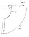
- FIG. 2 a modified diffuser in accordance with an example of the invention is shown overlaid over the diffuser of FIG. 1 (shown as dashed lines 121 ).
- the new diffuser has a higher number of straight parts (3 over 4) and a higher order curve 21 following the straight parts.
- the curve 21 is essentially an elliptical curve.
- the elliptical shape 21 has a higher curvature at the beginning or entry and flares out into a flatter part towards the exit 123 compared to the circular curve 121 (dashed).
- Other numerals in FIG. 2 are the same as in FIG. 1 . when denoting identical or similar elements.
- FIG. 3 A comparison of the efficiency of the two designs of FIG. 2 is shown in FIG. 3 illustrating the slice diffuser recovery.
- the graph is a plot of the recovery Chi between the diffuser inlet (last stage blade exit) and the diffuser exit (2R plane)over the medium speed in axial direction C z ⁇ in m/s at the diffuser inlet.
- the upper line illustrates the recovery of the new diffuser. This recovery is at least 3 per cent above the line of a known diffuser as shown in FIG. 1 . From this comparison it becomes clear that hybrid diffusers in accordance with the invention have the potential to improve diffuser recovery in a significant manner.
- the hybrid diffuser with 4 or more straight parts followed by an elliptical can be regarded as the one with a better improvement potential than the prior art diffuser of FIG. 1 .
- a diffuser with a higher number of straight parts and their respective lengths angles between them followed by a curve of the general shape a 11 ⁇ x 2 + a 12 ⁇ xy + a 22 ⁇ y 2 + 2 ⁇ a 13 ⁇ x + 2 ⁇ a 23 ⁇ y + a 33 0 with at least one mixed coefficient not being zero has a higher potential of being further improved than the more limited designs following the prior art.
- Such optimisation can be made using any of the known tools such as ANSYS CFX or other methods as described in the above referenced GT2011 publication.
Landscapes
- Engineering & Computer Science (AREA)
- Mechanical Engineering (AREA)
- General Engineering & Computer Science (AREA)
- Turbine Rotor Nozzle Sealing (AREA)
- Structures Of Non-Positive Displacement Pumps (AREA)
Description
- The present invention relates to improvements to a diffuser for a turbomachine. It is particularly, but not exclusively, relevant to the diffuser following the last stage of a low pressure (LP) steam turbine.
- Diffusers as found in large steam turbines are used for example to guide the steam from the last stage of the turbine to a condenser. Such a diffuser has two or more essentially concentric walls arranged at least initially with an axial orientation around the rotor axis of the turbine.
- As described for example in the United States patent no.
6,602,046 the diffuser following the last stage has tasks of decelerating the flowing medium, increasing the usable pressure or enthalpy drop across the turbines, converting a proportion of the kinetic energy to pressure energy and reducing flow losses at the diffuser outlet toward the condenser groups. It is hence clear that the design of the diffuser contributes to the overall efficiency of a turbine machine and for that reason many efforts have been made to optimize the diffuser layout. - In a document published at the GT2011, Proceedings of ASME Turbo Expo 2011, June 6-10 2011 in Vancouver BC, Ca. by Ch. Musch, H, Stuer and G. Hermle entitled "OPTIMIZATION STRATEGY FOR A COUPLED DESIGN OF THE LAST STAGE AND THE SUCCESSIVE DIFFUSER IN A LOW PRESSURE ENVIRONMENT, the authors present a diffuser design with outer wall cross-section consisting of two straight lines at an angle followed by an arc and another straight section at an outlet in radial directions.
- As described in the '046 patent, the straight lines can be formed as a sequence of kinks in the wall of the diffuser to deliberately cause flow separation from the wall. The configuration allows shock boundary layer pulsations to be suppressed. However, the measure may be associated with a considerable reduction in the diffuser efficiency.
- A further example of a diffuser comprising straight parts is provided in European Patent application
EP1921278A . As discussed in this application, it may be advantagoues to geometrically smooth the curves created by the straight parts. - A yet further example is provided by
U.S patent publication no. 3802187 . Described is an exhaust system for a rear drive tubeo shaft gas turbine. The exhaust comprises a concial shaped diffuser connected to an elbow duct having an elliptical shaped outlet. - In view of the existing prior art it can be seen as an object of the present to further optimize the existing diffuser designs and thus increase the efficiency of the turbomachines, particularly low pressure modules or turbines of a steam driven power plant.
- According to an aspect of the present invention, there is provided a diffuser having an outer wall having an entry section close to the last stage of a turbine including several subsequent straight sections at an angle to each other followed by a curved section with the curved section having as vertical cross-section a 2nd order curve, preferable a segment of an ellipse but excluding circle segments.
- A 2nd order curve excluding circles can be described for example as an algebraic equation of Cartesian coordinates in the form:

- It is found that using an elliptical shaped diffuser lip, a better diffuser design in terms of aerodynamics and performance is made possible. Particularly it is possible to have a higher curvature at the in-flow direction at the first part of the curved section and a reduced curvature towards the diffuser outlet. It is further possible to optimize the flare (or opening) angle of the diffuser and area ratio much closer to an ideal value than with an arc as due to the tip jet of the last stage blade, more turning of the flow in the diffuser can be done within the first angled straight sections or kinks.
- These and further aspects of the invention will be apparent from the following detailed description and drawings as listed below.
- Exemplary embodiments of the invention will now be described, with reference to the accompanying drawings, in which:
- FIG. 1
- shows a schematic vertical cross-section of a diffuser for a low pressure steam turbine stage as known with potential optimization parameters;
- FIG. 2
- shows a schematic vertical cross-section of a diffuser in accordance with an example of the invention overlaid over the known diffuser of
FIG. 1 ; and - FIG. 3
- is a plot of slice diffuser recovery illustrating the potential efficiency gains of diffusers in accordance with the present invention over known diffusers.
- Aspects and details of examples of the present invention are described in further details in the following description using the example of a diffuser for the a low pressure steam turbine.
- In
FIG. 1 there is shown a schematic vertical cross-section of a diffuser for a low pressure steam turbine stage as proposed in the GT2011 publication as referenced above. The figure shows a cross-section of the upper half of an essentially rotationally symmetrical diffuser. It also shows a part of therotor 10 and of theinner casing 11. Between the rotor and the casing and attached to one, respectively, are rotating blades and stator blades. The last stage of the turbine includes a circumferential arrangement ofstator blades 111 attached to thecasing 11 and a circumferential arrangement of rotatingblades 101 attached to therotor 10. - Following the last stage 111,101 is the
diffuser 12. It has anouter wall 121 and aninner wall 122, which together form an annular conduit guiding the steam to a condenser (not shown). The enlarged detail ofFIG. 1 shows a part of theouter wall 121 of the diffuser and illustrates the parameters which can be used to optimize the diffuser for a given turbine and steam flow. Following the direction of the steam flow, the wall has first straight part of length I1 followed by a second straight part of length I2. The second straight part forms an angle δ1 with respect to a horizontal line, i.e. in axial direction. The two straight parts are followed by a curved part. The curved part has an angle δ2 with respect to a horizontal line at its entry and a radius of R and an angle δ3 with respect to a horizontal line at its exit. The arc is followed by another essentially straight section with the length I3 in direction of theexit 123. As described in the GT2011 reference all the parameters shown can be altered in order to configure an optimizeddiffuser 12. - In
FIG. 2 a modified diffuser in accordance with an example of the invention is shown overlaid over the diffuser ofFIG. 1 (shown as dashed lines 121). The new diffuser has a higher number of straight parts (3 over 4) and ahigher order curve 21 following the straight parts. Thecurve 21 is essentially an elliptical curve. - As shown in
FIG. 2 , theelliptical shape 21 has a higher curvature at the beginning or entry and flares out into a flatter part towards theexit 123 compared to the circular curve 121 (dashed). Other numerals inFIG. 2 are the same as inFIG. 1 . when denoting identical or similar elements. - A comparison of the efficiency of the two designs of
FIG. 2 is shown inFIG. 3 illustrating the slice diffuser recovery. The graph is a plot of the recovery Chi between the diffuser inlet (last stage blade exit) and the diffuser exit (2R plane)over the medium speed in axial direction Czω in m/s at the diffuser inlet. The upper line illustrates the recovery of the new diffuser. This recovery is at least 3 per cent above the line of a known diffuser as shown inFIG. 1 . From this comparison it becomes clear that hybrid diffusers in accordance with the invention have the potential to improve diffuser recovery in a significant manner. The hybrid diffuser with 4 or more straight parts followed by an elliptical can be regarded as the one with a better improvement potential than the prior art diffuser ofFIG. 1 . - A diffuser with a higher number of straight parts and their respective lengths angles between them followed by a curve of the general shape

- The present invention has been described above purely by way of example, and modifications can be made within the scope of the invention. The invention may also comprise any individual features described or implicit herein or shown or implicit in the drawings or any combination of any such features or any generalization of any such features or combination, which extends to equivalents thereof. Thus, the breadth and scope of the present invention should not be limited by any of the above-described exemplary embodiments.
- Each feature disclosed in the specification, including the drawings, may be replaced by alternative features serving the same, equivalent or similar purposes, unless expressly stated otherwise.
- Unless explicitly stated herein, any discussion of the prior art throughout the specification is not an admission that such prior art is widely known or forms part of the common general knowledge in the field.
-
-
rotor 10 -
inner casing 11 -
stator blades 111 -
rotating blades 101 -
diffuser 12 - length of straight part I1
- length of straight part I2
- length of straight part I3
- angles δ2, δ3
- radius of circle segment R
-
exit 123 -
curve 21
Claims (2)
- A diffuser following the last stage of a turbine having an outer wall (121) with an entry section including several subsequent straight wall parts at an angle to each other, characterized in that the straight wall parts are followed by a curved wall part with the curved section connecting the straight parts to a diffuser lip or exit and having as its vertical cross-section a 2nd order elliptical curve.
- The diffuser of claim 1, wherein the number of straight parts is four or more.
Priority Applications (4)
| Application Number | Priority Date | Filing Date | Title |
|---|---|---|---|
| EP12172393.6A EP2677123B2 (en) | 2012-06-18 | 2012-06-18 | Diffuser for turbomachines |
| US13/919,332 US20130336783A1 (en) | 2012-06-18 | 2013-06-17 | Diffuser for turbomachines |
| JP2013127715A JP5726236B2 (en) | 2012-06-18 | 2013-06-18 | Diffuser for turbomachinery |
| CN201310240850.4A CN103511008B (en) | 2012-06-18 | 2013-06-18 | Diffuser for turbomachines |
Applications Claiming Priority (1)
| Application Number | Priority Date | Filing Date | Title |
|---|---|---|---|
| EP12172393.6A EP2677123B2 (en) | 2012-06-18 | 2012-06-18 | Diffuser for turbomachines |
Publications (3)
| Publication Number | Publication Date |
|---|---|
| EP2677123A1 EP2677123A1 (en) | 2013-12-25 |
| EP2677123B1 true EP2677123B1 (en) | 2014-10-08 |
| EP2677123B2 EP2677123B2 (en) | 2018-04-25 |
Family
ID=46318990
Family Applications (1)
| Application Number | Title | Priority Date | Filing Date |
|---|---|---|---|
| EP12172393.6A Active EP2677123B2 (en) | 2012-06-18 | 2012-06-18 | Diffuser for turbomachines |
Country Status (4)
| Country | Link |
|---|---|
| US (1) | US20130336783A1 (en) |
| EP (1) | EP2677123B2 (en) |
| JP (1) | JP5726236B2 (en) |
| CN (1) | CN103511008B (en) |
Families Citing this family (1)
| Publication number | Priority date | Publication date | Assignee | Title |
|---|---|---|---|---|
| JP7458947B2 (en) * | 2020-09-15 | 2024-04-01 | 三菱重工コンプレッサ株式会社 | Steam turbine |
Family Cites Families (11)
| Publication number | Priority date | Publication date | Assignee | Title |
|---|---|---|---|---|
| US2960306A (en) * | 1956-01-16 | 1960-11-15 | Gen Motors Corp | Turbine |
| GB1050879A (en) * | 1965-01-28 | |||
| US3802187A (en) * | 1972-06-01 | 1974-04-09 | Avco Corp | Exhaust system for rear drive engine |
| US4344737A (en) * | 1978-01-30 | 1982-08-17 | The Garrett Corporation | Crossover duct |
| DE3206626A1 (en) * | 1982-02-24 | 1983-09-01 | Kraftwerk Union AG, 4330 Mülheim | EXHAUST CHANNEL FOR GAS TURBINES |
| AT383396B (en) * | 1984-08-17 | 1987-06-25 | Proizv Ob Turbostroenia | LOW PRESSURE CYLINDERS OF A STEAM TURBINE |
| GB9415685D0 (en) * | 1994-08-03 | 1994-09-28 | Rolls Royce Plc | A gas turbine engine and a diffuser therefor |
| DE19905994A1 (en) | 1999-02-15 | 2000-08-24 | Peter Kraus | Procedure to prevent shock boundary layer pulsations with annular diffusers in steam turbines entails providing time-controlled blow-in excitation in rear shell region in dead water zone |
| EP1921278A1 (en) * | 2006-11-13 | 2008-05-14 | ALSTOM Technology Ltd | Diffuser and exhaust system for turbine |
| US8475125B2 (en) * | 2010-04-13 | 2013-07-02 | General Electric Company | Shroud vortex remover |
| US8591185B2 (en) * | 2010-11-16 | 2013-11-26 | General Electric Company | Low pressure exhaust gas diffuser for a steam turbine |
-
2012
- 2012-06-18 EP EP12172393.6A patent/EP2677123B2/en active Active
-
2013
- 2013-06-17 US US13/919,332 patent/US20130336783A1/en not_active Abandoned
- 2013-06-18 JP JP2013127715A patent/JP5726236B2/en active Active
- 2013-06-18 CN CN201310240850.4A patent/CN103511008B/en active Active
Also Published As
| Publication number | Publication date |
|---|---|
| CN103511008A (en) | 2014-01-15 |
| JP5726236B2 (en) | 2015-05-27 |
| CN103511008B (en) | 2015-07-15 |
| US20130336783A1 (en) | 2013-12-19 |
| EP2677123A1 (en) | 2013-12-25 |
| EP2677123B2 (en) | 2018-04-25 |
| JP2014001735A (en) | 2014-01-09 |
Similar Documents
| Publication | Publication Date | Title |
|---|---|---|
| US9739154B2 (en) | Axial turbomachine stator with ailerons at the blade roots | |
| JP6047141B2 (en) | High camber stator vane | |
| RU2598970C2 (en) | Bladed element for turbo-machine and turbo-machine itself | |
| CN107178425B (en) | Gas turbine engine and air vent assembly therein | |
| US9963973B2 (en) | Blading | |
| EP2484869A2 (en) | Strut airfoil design for low solidity exhaust gas diffuser | |
| JP6258325B2 (en) | Gas turbine engine having a radial diffuser and a shortened middle section | |
| US9631518B2 (en) | Exhaust diffuser and method for manufacturing an exhaust diffuser | |
| US11131205B2 (en) | Inter-turbine ducts with flow control mechanisms | |
| EP2554793B1 (en) | Inter-turbine ducts with guide vanes of a gas turbine engine | |
| US20140137533A1 (en) | Exhaust gas diffuser for a gas turbine | |
| EP2412922A1 (en) | Low-pressure steam turbine and method for operating thereof | |
| JP2015526691A (en) | Gas turbine engine having a shortened middle section | |
| WO2019027661A1 (en) | Gas turbine exhaust diffuser having flow guiding elements | |
| US20130136619A1 (en) | Blading | |
| JP2012082826A (en) | Turbine bucket shroud tail | |
| EP2639404A1 (en) | Exhaust diffuser for a turbine | |
| US8870532B2 (en) | Exhaust hood diffuser | |
| EP2677123B1 (en) | Diffuser for turbomachines | |
| EP2295732A1 (en) | Axial turbine and method for discharging a flow from an axial turbine | |
| EP3168416B1 (en) | Gas turbine | |
| CN113202789A (en) | Impeller for centrifugal compressor and centrifugal compressor | |
| WO2016033465A1 (en) | Gas turbine blade tip shroud flow guiding features | |
| EP2126367B1 (en) | Turbogas system multistage compressor | |
| JP2011236771A (en) | Exhaust diffuser for gas turbine and gas turbine provided with the same |
Legal Events
| Date | Code | Title | Description |
|---|---|---|---|
| PUAI | Public reference made under article 153(3) epc to a published international application that has entered the european phase |
Free format text: ORIGINAL CODE: 0009012 |
|
| AK | Designated contracting states |
Kind code of ref document: A1 Designated state(s): AL AT BE BG CH CY CZ DE DK EE ES FI FR GB GR HR HU IE IS IT LI LT LU LV MC MK MT NL NO PL PT RO RS SE SI SK SM TR |
|
| AX | Request for extension of the european patent |
Extension state: BA ME |
|
| 17P | Request for examination filed |
Effective date: 20140307 |
|
| RBV | Designated contracting states (corrected) |
Designated state(s): AL AT BE BG CH CY CZ DE DK EE ES FI FR GB GR HR HU IE IS IT LI LT LU LV MC MK MT NL NO PL PT RO RS SE SI SK SM TR |
|
| GRAP | Despatch of communication of intention to grant a patent |
Free format text: ORIGINAL CODE: EPIDOSNIGR1 |
|
| RIC1 | Information provided on ipc code assigned before grant |
Ipc: F01D 25/30 20060101AFI20140616BHEP Ipc: F01D 1/02 20060101ALI20140616BHEP |
|
| INTG | Intention to grant announced |
Effective date: 20140715 |
|
| GRAS | Grant fee paid |
Free format text: ORIGINAL CODE: EPIDOSNIGR3 |
|
| GRAA | (expected) grant |
Free format text: ORIGINAL CODE: 0009210 |
|
| AK | Designated contracting states |
Kind code of ref document: B1 Designated state(s): AL AT BE BG CH CY CZ DE DK EE ES FI FR GB GR HR HU IE IS IT LI LT LU LV MC MK MT NL NO PL PT RO RS SE SI SK SM TR |
|
| REG | Reference to a national code |
Ref country code: GB Ref legal event code: FG4D |
|
| REG | Reference to a national code |
Ref country code: AT Ref legal event code: REF Ref document number: 690753 Country of ref document: AT Kind code of ref document: T Effective date: 20141015 Ref country code: CH Ref legal event code: EP |
|
| REG | Reference to a national code |
Ref country code: IE Ref legal event code: FG4D |
|
| REG | Reference to a national code |
Ref country code: DE Ref legal event code: R096 Ref document number: 602012003312 Country of ref document: DE Effective date: 20141120 |
|
| REG | Reference to a national code |
Ref country code: NL Ref legal event code: VDEP Effective date: 20141008 |
|
| REG | Reference to a national code |
Ref country code: AT Ref legal event code: MK05 Ref document number: 690753 Country of ref document: AT Kind code of ref document: T Effective date: 20141008 |
|
| REG | Reference to a national code |
Ref country code: LT Ref legal event code: MG4D |
|
| PG25 | Lapsed in a contracting state [announced via postgrant information from national office to epo] |
Ref country code: NL Free format text: LAPSE BECAUSE OF FAILURE TO SUBMIT A TRANSLATION OF THE DESCRIPTION OR TO PAY THE FEE WITHIN THE PRESCRIBED TIME-LIMIT Effective date: 20141008 |
|
| PG25 | Lapsed in a contracting state [announced via postgrant information from national office to epo] |
Ref country code: IS Free format text: LAPSE BECAUSE OF FAILURE TO SUBMIT A TRANSLATION OF THE DESCRIPTION OR TO PAY THE FEE WITHIN THE PRESCRIBED TIME-LIMIT Effective date: 20150208 Ref country code: NO Free format text: LAPSE BECAUSE OF FAILURE TO SUBMIT A TRANSLATION OF THE DESCRIPTION OR TO PAY THE FEE WITHIN THE PRESCRIBED TIME-LIMIT Effective date: 20150108 Ref country code: PT Free format text: LAPSE BECAUSE OF FAILURE TO SUBMIT A TRANSLATION OF THE DESCRIPTION OR TO PAY THE FEE WITHIN THE PRESCRIBED TIME-LIMIT Effective date: 20150209 Ref country code: LT Free format text: LAPSE BECAUSE OF FAILURE TO SUBMIT A TRANSLATION OF THE DESCRIPTION OR TO PAY THE FEE WITHIN THE PRESCRIBED TIME-LIMIT Effective date: 20141008 Ref country code: ES Free format text: LAPSE BECAUSE OF FAILURE TO SUBMIT A TRANSLATION OF THE DESCRIPTION OR TO PAY THE FEE WITHIN THE PRESCRIBED TIME-LIMIT Effective date: 20141008 Ref country code: FI Free format text: LAPSE BECAUSE OF FAILURE TO SUBMIT A TRANSLATION OF THE DESCRIPTION OR TO PAY THE FEE WITHIN THE PRESCRIBED TIME-LIMIT Effective date: 20141008 |
|
| PG25 | Lapsed in a contracting state [announced via postgrant information from national office to epo] |
Ref country code: SE Free format text: LAPSE BECAUSE OF FAILURE TO SUBMIT A TRANSLATION OF THE DESCRIPTION OR TO PAY THE FEE WITHIN THE PRESCRIBED TIME-LIMIT Effective date: 20141008 Ref country code: RS Free format text: LAPSE BECAUSE OF FAILURE TO SUBMIT A TRANSLATION OF THE DESCRIPTION OR TO PAY THE FEE WITHIN THE PRESCRIBED TIME-LIMIT Effective date: 20141008 Ref country code: AT Free format text: LAPSE BECAUSE OF FAILURE TO SUBMIT A TRANSLATION OF THE DESCRIPTION OR TO PAY THE FEE WITHIN THE PRESCRIBED TIME-LIMIT Effective date: 20141008 Ref country code: LV Free format text: LAPSE BECAUSE OF FAILURE TO SUBMIT A TRANSLATION OF THE DESCRIPTION OR TO PAY THE FEE WITHIN THE PRESCRIBED TIME-LIMIT Effective date: 20141008 Ref country code: CY Free format text: LAPSE BECAUSE OF FAILURE TO SUBMIT A TRANSLATION OF THE DESCRIPTION OR TO PAY THE FEE WITHIN THE PRESCRIBED TIME-LIMIT Effective date: 20141008 Ref country code: HR Free format text: LAPSE BECAUSE OF FAILURE TO SUBMIT A TRANSLATION OF THE DESCRIPTION OR TO PAY THE FEE WITHIN THE PRESCRIBED TIME-LIMIT Effective date: 20141008 Ref country code: GR Free format text: LAPSE BECAUSE OF FAILURE TO SUBMIT A TRANSLATION OF THE DESCRIPTION OR TO PAY THE FEE WITHIN THE PRESCRIBED TIME-LIMIT Effective date: 20150109 Ref country code: PL Free format text: LAPSE BECAUSE OF FAILURE TO SUBMIT A TRANSLATION OF THE DESCRIPTION OR TO PAY THE FEE WITHIN THE PRESCRIBED TIME-LIMIT Effective date: 20141008 |
|
| REG | Reference to a national code |
Ref country code: DE Ref legal event code: R026 Ref document number: 602012003312 Country of ref document: DE |
|
| PLBI | Opposition filed |
Free format text: ORIGINAL CODE: 0009260 |
|
| 26 | Opposition filed |
Opponent name: SIEMENS AKTIENGESELLSCHAFT Effective date: 20150611 |
|
| PG25 | Lapsed in a contracting state [announced via postgrant information from national office to epo] |
Ref country code: CZ Free format text: LAPSE BECAUSE OF FAILURE TO SUBMIT A TRANSLATION OF THE DESCRIPTION OR TO PAY THE FEE WITHIN THE PRESCRIBED TIME-LIMIT Effective date: 20141008 Ref country code: DK Free format text: LAPSE BECAUSE OF FAILURE TO SUBMIT A TRANSLATION OF THE DESCRIPTION OR TO PAY THE FEE WITHIN THE PRESCRIBED TIME-LIMIT Effective date: 20141008 Ref country code: EE Free format text: LAPSE BECAUSE OF FAILURE TO SUBMIT A TRANSLATION OF THE DESCRIPTION OR TO PAY THE FEE WITHIN THE PRESCRIBED TIME-LIMIT Effective date: 20141008 Ref country code: SK Free format text: LAPSE BECAUSE OF FAILURE TO SUBMIT A TRANSLATION OF THE DESCRIPTION OR TO PAY THE FEE WITHIN THE PRESCRIBED TIME-LIMIT Effective date: 20141008 Ref country code: RO Free format text: LAPSE BECAUSE OF FAILURE TO SUBMIT A TRANSLATION OF THE DESCRIPTION OR TO PAY THE FEE WITHIN THE PRESCRIBED TIME-LIMIT Effective date: 20141008 |
|
| PLAX | Notice of opposition and request to file observation + time limit sent |
Free format text: ORIGINAL CODE: EPIDOSNOBS2 |
|
| PG25 | Lapsed in a contracting state [announced via postgrant information from national office to epo] |
Ref country code: IT Free format text: LAPSE BECAUSE OF FAILURE TO SUBMIT A TRANSLATION OF THE DESCRIPTION OR TO PAY THE FEE WITHIN THE PRESCRIBED TIME-LIMIT Effective date: 20141008 |
|
| PLBB | Reply of patent proprietor to notice(s) of opposition received |
Free format text: ORIGINAL CODE: EPIDOSNOBS3 |
|
| PG25 | Lapsed in a contracting state [announced via postgrant information from national office to epo] |
Ref country code: MC Free format text: LAPSE BECAUSE OF FAILURE TO SUBMIT A TRANSLATION OF THE DESCRIPTION OR TO PAY THE FEE WITHIN THE PRESCRIBED TIME-LIMIT Effective date: 20141008 |
|
| REG | Reference to a national code |
Ref country code: CH Ref legal event code: PL |
|
| PG25 | Lapsed in a contracting state [announced via postgrant information from national office to epo] |
Ref country code: SI Free format text: LAPSE BECAUSE OF FAILURE TO SUBMIT A TRANSLATION OF THE DESCRIPTION OR TO PAY THE FEE WITHIN THE PRESCRIBED TIME-LIMIT Effective date: 20141008 Ref country code: LU Free format text: LAPSE BECAUSE OF FAILURE TO SUBMIT A TRANSLATION OF THE DESCRIPTION OR TO PAY THE FEE WITHIN THE PRESCRIBED TIME-LIMIT Effective date: 20150618 |
|
| REG | Reference to a national code |
Ref country code: IE Ref legal event code: MM4A |
|
| REG | Reference to a national code |
Ref country code: FR Ref legal event code: ST Effective date: 20160229 |
|
| PG25 | Lapsed in a contracting state [announced via postgrant information from national office to epo] |
Ref country code: IE Free format text: LAPSE BECAUSE OF NON-PAYMENT OF DUE FEES Effective date: 20150618 Ref country code: CH Free format text: LAPSE BECAUSE OF NON-PAYMENT OF DUE FEES Effective date: 20150630 Ref country code: LI Free format text: LAPSE BECAUSE OF NON-PAYMENT OF DUE FEES Effective date: 20150630 |
|
| PG25 | Lapsed in a contracting state [announced via postgrant information from national office to epo] |
Ref country code: FR Free format text: LAPSE BECAUSE OF NON-PAYMENT OF DUE FEES Effective date: 20150630 |
|
| REG | Reference to a national code |
Ref country code: DE Ref legal event code: R082 Ref document number: 602012003312 Country of ref document: DE Representative=s name: RUEGER, BARTHELT & ABEL, DE Ref country code: DE Ref legal event code: R082 Ref document number: 602012003312 Country of ref document: DE Representative=s name: RUEGER | ABEL PATENT- UND RECHTSANWAELTE, DE Ref country code: DE Ref legal event code: R082 Ref document number: 602012003312 Country of ref document: DE Representative=s name: RUEGER ABEL PATENT- UND RECHTSANWAELTE, DE Ref country code: DE Ref legal event code: R081 Ref document number: 602012003312 Country of ref document: DE Owner name: GENERAL ELECTRIC TECHNOLOGY GMBH, CH Free format text: FORMER OWNER: ALSTOM TECHNOLOGY LTD., BADEN, CH |
|
| RAP2 | Party data changed (patent owner data changed or rights of a patent transferred) |
Owner name: GENERAL ELECTRIC TECHNOLOGY GMBH |
|
| PG25 | Lapsed in a contracting state [announced via postgrant information from national office to epo] |
Ref country code: MT Free format text: LAPSE BECAUSE OF FAILURE TO SUBMIT A TRANSLATION OF THE DESCRIPTION OR TO PAY THE FEE WITHIN THE PRESCRIBED TIME-LIMIT Effective date: 20141008 |
|
| GBPC | Gb: european patent ceased through non-payment of renewal fee |
Effective date: 20160618 |
|
| PG25 | Lapsed in a contracting state [announced via postgrant information from national office to epo] |
Ref country code: GB Free format text: LAPSE BECAUSE OF NON-PAYMENT OF DUE FEES Effective date: 20160618 Ref country code: SM Free format text: LAPSE BECAUSE OF FAILURE TO SUBMIT A TRANSLATION OF THE DESCRIPTION OR TO PAY THE FEE WITHIN THE PRESCRIBED TIME-LIMIT Effective date: 20141008 Ref country code: HU Free format text: LAPSE BECAUSE OF FAILURE TO SUBMIT A TRANSLATION OF THE DESCRIPTION OR TO PAY THE FEE WITHIN THE PRESCRIBED TIME-LIMIT; INVALID AB INITIO Effective date: 20120618 Ref country code: BG Free format text: LAPSE BECAUSE OF FAILURE TO SUBMIT A TRANSLATION OF THE DESCRIPTION OR TO PAY THE FEE WITHIN THE PRESCRIBED TIME-LIMIT Effective date: 20141008 |
|
| PG25 | Lapsed in a contracting state [announced via postgrant information from national office to epo] |
Ref country code: TR Free format text: LAPSE BECAUSE OF FAILURE TO SUBMIT A TRANSLATION OF THE DESCRIPTION OR TO PAY THE FEE WITHIN THE PRESCRIBED TIME-LIMIT Effective date: 20141008 |
|
| PG25 | Lapsed in a contracting state [announced via postgrant information from national office to epo] |
Ref country code: BE Free format text: LAPSE BECAUSE OF FAILURE TO SUBMIT A TRANSLATION OF THE DESCRIPTION OR TO PAY THE FEE WITHIN THE PRESCRIBED TIME-LIMIT Effective date: 20141008 |
|
| PLAB | Opposition data, opponent's data or that of the opponent's representative modified |
Free format text: ORIGINAL CODE: 0009299OPPO |
|
| R26 | Opposition filed (corrected) |
Opponent name: SIEMENS AKTIENGESELLSCHAFT Effective date: 20150611 |
|
| PUAH | Patent maintained in amended form |
Free format text: ORIGINAL CODE: 0009272 |
|
| STAA | Information on the status of an ep patent application or granted ep patent |
Free format text: STATUS: PATENT MAINTAINED AS AMENDED |
|
| 27A | Patent maintained in amended form |
Effective date: 20180425 |
|
| AK | Designated contracting states |
Kind code of ref document: B2 Designated state(s): AL AT BE BG CH CY CZ DE DK EE ES FI FR GB GR HR HU IE IS IT LI LT LU LV MC MK MT NL NO PL PT RO RS SE SI SK SM TR |
|
| REG | Reference to a national code |
Ref country code: DE Ref legal event code: R102 Ref document number: 602012003312 Country of ref document: DE |
|
| PG25 | Lapsed in a contracting state [announced via postgrant information from national office to epo] |
Ref country code: MK Free format text: LAPSE BECAUSE OF FAILURE TO SUBMIT A TRANSLATION OF THE DESCRIPTION OR TO PAY THE FEE WITHIN THE PRESCRIBED TIME-LIMIT Effective date: 20141008 |
|
| PG25 | Lapsed in a contracting state [announced via postgrant information from national office to epo] |
Ref country code: AL Free format text: LAPSE BECAUSE OF FAILURE TO SUBMIT A TRANSLATION OF THE DESCRIPTION OR TO PAY THE FEE WITHIN THE PRESCRIBED TIME-LIMIT Effective date: 20141008 |
|
| REG | Reference to a national code |
Ref country code: DE Ref legal event code: R082 Ref document number: 602012003312 Country of ref document: DE |
|
| P01 | Opt-out of the competence of the unified patent court (upc) registered |
Effective date: 20230523 |
|
| PGFP | Annual fee paid to national office [announced via postgrant information from national office to epo] |
Ref country code: DE Payment date: 20240521 Year of fee payment: 13 |