EP2676872B1 - Sous-bloc optique, bloc optique, système de bloc optique pour véhicule qui penche dans les virages, véhicule qui penche dans les virages et procédé pour commander le sous-bloc optique pour véhicule qui penche dans les virages - Google Patents
Sous-bloc optique, bloc optique, système de bloc optique pour véhicule qui penche dans les virages, véhicule qui penche dans les virages et procédé pour commander le sous-bloc optique pour véhicule qui penche dans les virages Download PDFInfo
- Publication number
- EP2676872B1 EP2676872B1 EP12192580.4A EP12192580A EP2676872B1 EP 2676872 B1 EP2676872 B1 EP 2676872B1 EP 12192580 A EP12192580 A EP 12192580A EP 2676872 B1 EP2676872 B1 EP 2676872B1
- Authority
- EP
- European Patent Office
- Prior art keywords
- light source
- sub
- vehicle
- sub headlight
- headlight
- Prior art date
- Legal status (The legal status is an assumption and is not a legal conclusion. Google has not performed a legal analysis and makes no representation as to the accuracy of the status listed.)
- Active
Links
- 238000000034 method Methods 0.000 title claims description 21
- 238000005286 illumination Methods 0.000 claims description 118
- 238000001514 detection method Methods 0.000 claims description 17
- 238000009826 distribution Methods 0.000 description 22
- 238000010586 diagram Methods 0.000 description 16
- 241001417501 Lobotidae Species 0.000 description 12
- 238000004364 calculation method Methods 0.000 description 4
- 238000012937 correction Methods 0.000 description 4
- 230000004313 glare Effects 0.000 description 4
- 230000005855 radiation Effects 0.000 description 4
- 230000003247 decreasing effect Effects 0.000 description 3
- 238000009434 installation Methods 0.000 description 3
- 238000012360 testing method Methods 0.000 description 3
- 230000001419 dependent effect Effects 0.000 description 2
- 230000006870 function Effects 0.000 description 2
- 238000009827 uniform distribution Methods 0.000 description 2
- 230000003044 adaptive effect Effects 0.000 description 1
- 238000006243 chemical reaction Methods 0.000 description 1
- 238000004891 communication Methods 0.000 description 1
- 238000012545 processing Methods 0.000 description 1
- 230000004044 response Effects 0.000 description 1
Images


Classifications
-
- B—PERFORMING OPERATIONS; TRANSPORTING
- B60—VEHICLES IN GENERAL
- B60Q—ARRANGEMENT OF SIGNALLING OR LIGHTING DEVICES, THE MOUNTING OR SUPPORTING THEREOF OR CIRCUITS THEREFOR, FOR VEHICLES IN GENERAL
- B60Q1/00—Arrangement of optical signalling or lighting devices, the mounting or supporting thereof or circuits therefor
- B60Q1/02—Arrangement of optical signalling or lighting devices, the mounting or supporting thereof or circuits therefor the devices being primarily intended to illuminate the way ahead or to illuminate other areas of way or environments
- B60Q1/04—Arrangement of optical signalling or lighting devices, the mounting or supporting thereof or circuits therefor the devices being primarily intended to illuminate the way ahead or to illuminate other areas of way or environments the devices being headlights
- B60Q1/06—Arrangement of optical signalling or lighting devices, the mounting or supporting thereof or circuits therefor the devices being primarily intended to illuminate the way ahead or to illuminate other areas of way or environments the devices being headlights adjustable, e.g. remotely-controlled from inside vehicle
- B60Q1/08—Arrangement of optical signalling or lighting devices, the mounting or supporting thereof or circuits therefor the devices being primarily intended to illuminate the way ahead or to illuminate other areas of way or environments the devices being headlights adjustable, e.g. remotely-controlled from inside vehicle automatically
- B60Q1/12—Arrangement of optical signalling or lighting devices, the mounting or supporting thereof or circuits therefor the devices being primarily intended to illuminate the way ahead or to illuminate other areas of way or environments the devices being headlights adjustable, e.g. remotely-controlled from inside vehicle automatically due to steering position
-
- B—PERFORMING OPERATIONS; TRANSPORTING
- B60—VEHICLES IN GENERAL
- B60Q—ARRANGEMENT OF SIGNALLING OR LIGHTING DEVICES, THE MOUNTING OR SUPPORTING THEREOF OR CIRCUITS THEREFOR, FOR VEHICLES IN GENERAL
- B60Q1/00—Arrangement of optical signalling or lighting devices, the mounting or supporting thereof or circuits therefor
- B60Q1/02—Arrangement of optical signalling or lighting devices, the mounting or supporting thereof or circuits therefor the devices being primarily intended to illuminate the way ahead or to illuminate other areas of way or environments
- B60Q1/04—Arrangement of optical signalling or lighting devices, the mounting or supporting thereof or circuits therefor the devices being primarily intended to illuminate the way ahead or to illuminate other areas of way or environments the devices being headlights
- B60Q1/18—Arrangement of optical signalling or lighting devices, the mounting or supporting thereof or circuits therefor the devices being primarily intended to illuminate the way ahead or to illuminate other areas of way or environments the devices being headlights being additional front lights
-
- B—PERFORMING OPERATIONS; TRANSPORTING
- B62—LAND VEHICLES FOR TRAVELLING OTHERWISE THAN ON RAILS
- B62J—CYCLE SADDLES OR SEATS; AUXILIARY DEVICES OR ACCESSORIES SPECIALLY ADAPTED TO CYCLES AND NOT OTHERWISE PROVIDED FOR, e.g. ARTICLE CARRIERS OR CYCLE PROTECTORS
- B62J6/00—Arrangement of optical signalling or lighting devices on cycles; Mounting or supporting thereof; Circuits therefor
- B62J6/02—Headlights
- B62J6/022—Headlights specially adapted for motorcycles or the like
- B62J6/023—Headlights specially adapted for motorcycles or the like responsive to the lean angle of the cycle, e.g. changing intensity or switching sub-lights when cornering
-
- B—PERFORMING OPERATIONS; TRANSPORTING
- B62—LAND VEHICLES FOR TRAVELLING OTHERWISE THAN ON RAILS
- B62J—CYCLE SADDLES OR SEATS; AUXILIARY DEVICES OR ACCESSORIES SPECIALLY ADAPTED TO CYCLES AND NOT OTHERWISE PROVIDED FOR, e.g. ARTICLE CARRIERS OR CYCLE PROTECTORS
- B62J6/00—Arrangement of optical signalling or lighting devices on cycles; Mounting or supporting thereof; Circuits therefor
- B62J6/02—Headlights
- B62J6/022—Headlights specially adapted for motorcycles or the like
- B62J6/024—Switching between high and low beam
-
- B—PERFORMING OPERATIONS; TRANSPORTING
- B60—VEHICLES IN GENERAL
- B60Q—ARRANGEMENT OF SIGNALLING OR LIGHTING DEVICES, THE MOUNTING OR SUPPORTING THEREOF OR CIRCUITS THEREFOR, FOR VEHICLES IN GENERAL
- B60Q2300/00—Indexing codes for automatically adjustable headlamps or automatically dimmable headlamps
- B60Q2300/05—Special features for controlling or switching of the light beam
- B60Q2300/054—Variable non-standard intensity, i.e. emission of various beam intensities different from standard intensities, e.g. continuous or stepped transitions of intensity
-
- B—PERFORMING OPERATIONS; TRANSPORTING
- B60—VEHICLES IN GENERAL
- B60Q—ARRANGEMENT OF SIGNALLING OR LIGHTING DEVICES, THE MOUNTING OR SUPPORTING THEREOF OR CIRCUITS THEREFOR, FOR VEHICLES IN GENERAL
- B60Q2300/00—Indexing codes for automatically adjustable headlamps or automatically dimmable headlamps
- B60Q2300/10—Indexing codes relating to particular vehicle conditions
- B60Q2300/13—Attitude of the vehicle body
- B60Q2300/136—Roll
Definitions
- the present invention relates to a sub-headlight unit for a vehicle that leans into turns by tilting inward on a curve according to the preamble of independent claim 1, a headlight unit, and a headlight system for vehicles that lean into turns, to a vehicle that leans into turns, and to a method for controlling sub-headlight unit for a vehicle that leans into turns tilt inward on a curve according to the preamble of independent claim 12.
- a sub-headlight unit and such a method for controlling a sub-headlight unit can be taken from US 2010/168958 A1 .
- the operator of a vehicle that leans into turns uses weight shifts to counter the centrifugal force acting on the vehicle when steering into corners and intersections. As a result, the vehicle turns into a curve by tilting (leaning) inward.
- vehicles that do not lean into turns such as automobiles are steered into corners and intersections by the operator under the centrifugal force acting on the vehicle. The body of a vehicle that does not lean into turns thus tilts outward on a curve under centrifugal force.
- Vehicles that lean into turns involve a large tilt, because the operator actively uses weight shifts to make turns.
- vehicles that do not lean into turns tilt toward the outside of a curve under centrifugal force.
- the extent of the tilt depends on the traveling speed of the vehicle and the size (radius) of a curve; however, vehicles that do not lean into turns do not actually use the tilt to make turns.
- the outward tilting of a vehicle that does not lean into turns on a curve under centrifugal force should preferably be small.
- Vehicles whether leaning or not leaning into turns, are typically equipped with more than one light: those mainly used to provide visibility to the operator of the vehicle, and those that allow the vehicle to be seen by other road users.
- Headlights are mainly used to provide visibility to the operator of the vehicle, and are typically switchable between a high beam (driving headlight) and a low beam (passing headlight).
- High beams provide illumination horizontally (upwardly), and provide distant visibility. High beams are typically used in nighttime when other vehicles are not present ahead, in order to prevent dazzling the operators of the vehicles around. On the other hand, low beams provide light downward, and are also used when other vehicles and road users are present ahead. Vehicles thus typically use low beams for traveling.
- the illumination range of the low beam of a vehicle that leans into turns traveling along a straight road is below the horizontal plane including the headlight light source, and spreads forward with a laterally uniform distribution.
- the vehicle tilts leftward, and accordingly the illumination range of the headlight light source moves downward to the left. The light thus illuminates a point on the lane more toward the vehicle, and the illumination range becomes smaller inside the curve ahead in the direction of travel.
- JP-A-2008-222178 proposes a motorcycle in which high beam light sources are turned on with low beam light sources when the lean angle becomes at or above a predetermined value while the low beam light sources are on, so as to illuminate inside of the curve ahead in the direction of travel with the high beam light sources.
- the high beam light sources are turned on in predetermined numbers when the lean angle becomes at or above a predetermined value while the low beam light sources are on.
- the motorcycle is provided with a single high beam light source, and that the single high beam light source is turned on when the lean angle becomes at or above a predetermined value while the low beam light source is on.
- the high beam light source is intended to provide illumination forward in front of the vehicle, and as such the light distribution of the high beam light source is typically adjusted to suitably provide illumination forward in front of the vehicle.
- One way to solve this problem is to adjust the light distribution of the high beam light source in a manner allowing the light to illuminate inside of a curve.
- this makes the light distribution of the high beam light source unsuitable for providing illumination forward in front of the vehicle, and the high beam light source providing illumination forward in front of the vehicle might unnecessarily illuminate the space other than the forward and front direction of the vehicle.
- the motorcycle disclosed in the foregoing publication includes a plurality of high beam light sources, and predetermined numbers of high beam light sources in the plurality of high beam light sources are turned on when the lean angle becomes at or above a predetermined value while the low beam light sources are on.
- a problem of this motorcycle is that the size of the heat radiation mechanism necessary for the plurality of high beam light sources as a whole increase, because the on-time of the plurality of high beam light sources becomes long when the high beam light sources are turned on while vehicle is traveling.
- a headlight unit and system for a vehicle that leans into turns and a vehicle that leans into turns having the features of claim 9, 10 or 11.
- said object is solved by a method for controlling a sub-headlight unit for a vehicle that leans into turns having the features of independent claim 12.
- a sub-headlight unit for a vehicle that leans into turns comprising:
- the sub headlight light source has a cutoff line below the horizontal line of the sub headlight light source upon the lean angle of the vehicle reaching the low-beam reference value, and wherein the sub headlight light source has a cutoff line at least partially above the horizontal line of the sub headlight light source upon the lean angle of the vehicle reaching the high-beam reference value.
- the angle created by the cutoff line and the horizontal line of the sub headlight light source is smaller when the lean angle of the vehicle is at the low-beam reference value than when the lean angle of the vehicle is at the high-beam reference value.
- control unit is adapted to turn off the sub headlight light source in the upright state of the vehicle regardless of whether the low beam light source or the high beam light source is on.
- a height difference between a center of a maximum illuminance portion of the illumination light from the sub headlight light source and a center of a maximum illuminance portion of the illumination light from the high beam light source is smaller when the lean angle of the vehicle is at the high-beam reference value than when the sub headlight light source is on in the upright state of the vehicle.
- the sub-headlight unit comprises a plurality of the sub headlight light sources, the low-beam reference value and the high-beam reference value being set for each of the plurality of sub headlight light sources, and the low-beam reference value being different for the plurality of sub headlight light sources
- the control unit is adapted to turn on the plurality of sub headlight light sources in order from the sub headlight light sources having the smaller low-beam reference values as the lean angle to the one side of the vehicle increases while the low beam light source is on, and the high-beam reference value of the sub headlight light source that turns on later being equal to or greater than the high-beam reference value of the sub headlight light source that turns on earlier in the turn-on sequence of the plurality of sub headlight light sources while the low beam light source is on.
- the sub headlight light sources having the larger low-beam reference values have illumination ranges positioned further upward of the vehicle in the upright state of the vehicle.
- the sub headlight light source that turns on later with increasing lean angles of the vehicle has an illumination range of a predetermined illuminance whose outer edge is more outward relative to the width direction of the vehicle than the outer edge of the illumination range of a predetermined illuminance of the sub headlight light source that turns on earlier when the plurality of sub headlight light sources turns on with increasing lean angles of the vehicle, regardless of whether the low beam light source or the high beam light source is on.
- a headlight unit for a vehicle that leans into turns, the headlight unit comprising such a sub-headlight unit in a pair, and the low beam light source and the high beam light source, wherein one of the two sub-headlight units provides illumination light forward and outward of the width direction of the vehicle on the left side of the vehicle, and the other sub-headlight unit provides illumination light forward and outward of the width direction of the vehicle on the right side of the vehicle.
- a headlight system for a vehicle that leans into turns comprising:
- the vehicle that leans into turns, wherein the vehicle comprises such a headlight system.
- a method for controlling sub-headlight unit for a vehicle that leans into turns comprising:
- the method for controlling sub-headlight unit further comprises:
- the angle created by the cutoff line and the horizontal line of the sub headlight light source is set smaller when the lean angle of the vehicle is at the low-beam reference value than when the lean angle of the vehicle is at the high-beam reference value.
- the method for controlling sub-headlight unit further comprises:
- a height difference between a center of a maximum illuminance portion of the illumination light from the sub headlight light source and a center of a maximum illuminance portion of the illumination light from the high beam light source is set smaller when the lean angle of the vehicle is at the high-beam reference value than when the sub headlight light source is on in the upright state of the vehicle.
- the sub-headlight unit comprises a plurality of the sub headlight light sources, the method is further comprising:
- the present invention enables illumination to be desirably provided inside of a curve regardless of whether the low beam or the high beam is on, while suppressing a size increase.
- FIG. 1 is a partially enlarged front view schematically illustrating a motorcycle according to an embodiment.
- FIG. 2 is a partially enlarged left side view of the motorcycle illustrated in FIG. 1 .
- a motorcycle 10 represents an example of a vehicle that leans into turns of the present teaching.
- the vehicle that leans into turns is not particularly limited, and examples include straddle-type vehicles such as motorcycles, three-wheelers, snowmobiles, and ATVs (all-terrain vehicles).
- straddle-type vehicles such as motorcycles, three-wheelers, snowmobiles, and ATVs (all-terrain vehicles).
- the terms “longitudinal” and “vertical” are with respect to the traveling direction and the vertical direction, respectively, of the vehicle, and the terms “left” and "right” are with respect to the operator.
- the motorcycle 10 has a handle bar 12.
- An operation switch 15 is disposed on the handle bar 12 on the left side of the width direction of the vehicle.
- the operation switch 15 includes a beam switch 15B and a flasher switch 15F (see FIG. 3 ).
- a steering shaft (not illustrated) is fixed to the handle bar 12 at the middle portion of the width direction of the vehicle.
- the steering shaft extends downwardly through a head pipe (not illustrated).
- Front forks 17 are disposed at the lower end side of the steering shaft.
- a front wheel (not illustrated) is rotatably supported on the lower end side of the front forks 17.
- the head pipe is a component of the vehicle frame.
- the vehicle frame is not particularly limited, and may be realized by a structure known in the art.
- a front cover 18 is disposed in front of the head pipe through which the steering shaft is disposed.
- the front cover 18 is at the middle portion of the width direction of the motorcycle 10.
- a main headlight light source 11 is disposed inside the front cover 18.
- the main headlight light source 11 includes a high beam light source 11H (driving headlight) and a low beam light source 11L (passing headlight), though not illustrated in FIG. 1 .
- the high beam light source 11H provides illumination forward horizontally in front of the motorcycle 10, or upwardly from the horizontal direction.
- the low beam light source 11L of the motorcycle 10 provides forward and downward light below the horizontal direction.
- the motorcycle 10 includes a pair of sub-headlight units 13L and 13R of variable light distribution.
- the sub-headlight units 13L and 13R are disposed on each side of the width direction of the vehicle.
- the sub-headlight unit 13L includes a plurality of sub headlight light sources 13La, 13Lb, and 13Lc.
- the sub headlight light sources 13La, 13Lb, and 13Lc are arranged in order from the middle portion toward the upper left side relative to the width direction of the vehicle.
- the sub-headlight unit 13R includes a plurality of sub headlight light sources 13Ra, 13Rb, and 13Rc.
- the sub headlight light sources 13Ra, 13Rb, and 13Rc are arranged in order from the middle portion toward the upper right side relative to the width direction of the vehicle.
- the light axes of the sub headlight light sources 13La to 13Lc, and 13Ra to 13Rc are fixed, and do not move according to lean angle.
- the reflectors (not illustrated) of the sub headlight light sources are also fixed, and do not move with the lean angle.
- the sub headlight light sources are not particularly limited, and, for example, LEDs may be used.
- Mono-focusing light sources also may be used as the sub headlight light sources.
- the arrangement of the sub headlight light sources 13La to 13Lc, and 13Ra to 13Rc in the motorcycle 10 is merely an example of the present teaching, and the present invention is not limited to this example.
- the present invention is not limited to this example, and the sub headlight light sources may be disposed on the opposite side (for example, the right side) of the side (the left side) where the sub headlight light sources provide illumination.
- the sub headlight light sources that provide illumination on the left side, and the sub headlight light source that provide illumination on the right side of the width direction of the vehicle may be disposed by being vertically arranged at the middle portion of the width direction of the vehicle.
- the front end of the front cover 18 relative to the longitudinal direction of the vehicle is at the middle of the motorcycle 10.
- the front cover 18 has a curved surface that is rounded outward and that extends from the middle portion of the width direction of the vehicle on the front side of the vehicle toward the outer sides of the width direction of the vehicle and backward.
- the sub headlight light sources 13La to 13Lc and 13Ra to 13Rc are disposed along the curved surface of the front cover 18. Flashers 14L and 14R are disposed as direction indicators on each side of the width direction of the motorcycle 10.
- FIG. 3 is a block diagram representing a basic configuration of the sub headlight light sources of the motorcycle illustrated in FIG. 1 .
- the operation switch 15 includes the beam switch 15B and the flasher switch 15F.
- the beam switch 15B is connected to the high beam light source 11H and the low beam light source 11L of the main headlight light source 11.
- the ON/OFF of the high beam light source 11H and the low beam light source 11L are switched according to the intended operation of the beam switch 15B by the operator using the beam switch 15B.
- the flasher switch 15F is connected to the flashers 14L and 14R.
- One of the flashers 14L and 14R flashes according to the intended operation of the flasher switch 15F by the operator.
- the motorcycle 10 is equipped with a lean angle sensor 22 and a vehicle speed sensor 23.
- the lean angle sensor 22 is a gyroscope that detects the angular velocity around the longitudinal axis of the motorcycle 10, and sends to the controller 20 a signal indicative of the detected angular velocity (roll rate) around the longitudinal axis.
- the vehicle speed sensor 23 detects the vehicle speed, and sends to the controller 20 a signal indicative of the detected vehicle speed.
- the controller 20 calculates the lean angle of the motorcycle 10 in motion at each predetermined time point by using the vehicle speed, and the angular velocity around the longitudinal axis.
- the roll rate is time integrated, and the lean angle is calculated by using the vehicle speed as correction information.
- the lean angle calculation method is not limited to this example.
- the vehicle speed is not an essential variable in the lean angle calculation.
- the lean angle may be calculated by using methods known in the art.
- the lean angle may be calculated by using a steady-state balance equation, using the yaw rate (angular velocity around the vertical axis) and the vehicle speed.
- the correction information is not limited to vehicle speed.
- a plurality of gyroscopes and G sensors may be provided, and the values obtained from these sensors, and the vehicle speed may be used as correction information.
- GPS positional information and/or geomagnetic information may be used as correction information.
- the type of sensors (detection units) used for the detection of variables to find the lean angle are not particularly limited, and the sensors may be appropriately disposed according to the variables used for the calculations.
- the controller 20 includes a memory (not illustrated).
- the stored data in the memory include low-beam reference value KL (°) and high-beam reference value KH (°) for comparison with lean angle.
- the low-beam reference value corresponds to the lean angle at which the sub headlight light source turns on at a predetermined brightness while the low beam light source 11L is on.
- the high-beam reference value corresponds to the lean angle at which the sub headlight light source turns on at a predetermined brightness while the high beam light source 11H is on.
- three low-beam reference values, and three high-beam reference values are stored.
- the plurality of low-beam reference values KL 1 , KL 2 , and KL 3 are different (KL 1 ⁇ KL 2 ⁇ KL 3 ), and are assigned to the sub headlight light sources 13La, 13Lb, and 13Lc, respectively.
- the plurality of high-beam reference values KH 1 , KH 2 , and KH 3 are different (KH 1 ⁇ KH 2 ⁇ KH 3 ), and are assigned to the sub headlight light sources 13La, 13Lb, and 13Lc, respectively.
- the present teaching is not limited to this example, and, for example, the sub headlight light source (for example, 13Lb) that turns on later while the low beam light source 11L is on may have a high-beam reference value (KH 2 ) equal to or greater than the high-beam reference value (KH 1 ) of the sub headlight light source (for example, 13La) that turns on earlier in the turn-on sequence of the plurality of sub headlight light sources 13La to 13Lc (13La ⁇ 13Lb ⁇ 13Lc).
- the high-beam reference values KH 1 , KH 2 , and KH 3 may satisfy KH 1 ⁇ KH 2 ⁇ KH 3 .
- the high-beam reference value KH 1 set for one sub headlight light source (for example, 13La) is smaller than the low-beam reference value KL 1 set for the same sub headlight light source.
- the low-beam reference values KL 1 to KL 3 and the high-beam reference values KH 1 to KH 3 satisfy the relationships of KL n ⁇ KL n+1 , KH n ⁇ KH n+1 , and KH n ⁇ KL n , where n represents the order in which the sub headlight light sources turn on while the low beam light source 11L is on.
- the stored data in the memory include low-beam lower value TL (°) and high-beam lower value TH (°) for comparison with lean angle.
- the low-beam lower value TL and the high-beam lower value TH each correspond to the lean angle at which the brightness of the sub headlight light source starts to increase from the off state while the low beam light source 11L or the high beam light source 11H is on.
- the low-beam lower value TL and the high-beam lower value TH are assigned to each of the sub headlight light sources 13La to 13Lc.
- the low-beam lower values TL 1 to TL 3 and the high-beam lower values TH 1 to TH 3 satisfy the relationships of TL n ⁇ TL n+1 , TH n ⁇ TH n+1 , and TH n ⁇ TL n .
- the lower values are smaller than the reference values, satisfying TL n ⁇ KL n , and TH n ⁇ KH n .
- the stored data in the memory include low-beam upper value UL (°) and high-beam upper value UH (°) for comparison with lean angle.
- the low-beam upper value UL and the high-beam upper value UH each correspond to the lean angle at which the sub headlight light source starts to turn on at the maximum brightness as the lean angle increases while the low beam light source 11L or the high beam light source 11H is on.
- the low-beam upper value UL and the high-beam upper value UH are assigned to each of the sub headlight light sources 13La to 13Lc.
- the low-beam upper values UL 1 to UL 3 and the high-beam upper values UH 1 to UH 3 satisfy the relationships of UL n ⁇ UL n+1 , UH n ⁇ UH n+1 , and UH n ⁇ UL n .
- the upper values are larger than the reference values, satisfying KL n ⁇ UL n , and KH n ⁇ UH n .
- the stored data in the memory include low-beam specific value IL (°) and high-beam specific value IH (°) for comparison with lean angle.
- the low-beam specific value IL and the high-beam specific value IH each correspond to the lean angle at which the brightness of the sub headlight light source at the maximum brightness start to decrease as the lean angle increases while the low beam light source 11L or the high beam light source 11H is on.
- the low-beam specific value IL and the high-beam specific value IH are assigned to each of the sub headlight light sources 13La and 13Lb.
- the low-beam specific value IL and the high-beam specific value IH are not set for the sub headlight light source 13Lc having the largest reference values TL and TH.
- the low-beam specific values IL 1 and IL 2 and the high-beam specific values IH 1 and IH 2 satisfy the relationships of IL n ⁇ IL n+1 , IH n ⁇ IH n+1 , and IH n ⁇ IL n .
- the specific values are larger than the upper values, satisfying UL n ⁇ IL n , and UH n ⁇ IH n .
- the stored data in the memory include low-beam prescribed value JL (°) and high-beam prescribed value JH (°) for comparison with lean angle.
- the low-beam prescribed value JL and the high-beam prescribed value JH each correspond to the lean angle at which the brightness of the sub headlight light source becomes the lowest as the lean angle increases past the specific value IL or LH while the low beam light source 11L or the high beam light source 11H is on.
- the low-beam prescribed value JL and the high-beam prescribed value JH are assigned to each of the sub headlight light sources 13La and 13Lb.
- the low-beam prescribed value JL and the high-beam prescribed value JH are not set for the sub headlight light source 13Lc having the largest reference values TL and TH.
- the low-beam prescribed values JL 1 to JL 3 and the high-beam prescribed values JH 1 to JH 3 satisfy the relationships of JL n ⁇ JL n+1 , JH n ⁇ JH n+1 , and JH n ⁇ JL n .
- the prescribed values are larger than the specific values, satisfying IL n ⁇ JL n , and IH n ⁇ JH n .
- the low-beam variables and the high-beam variables are also each assigned to the sub headlight light sources 13Ra to 13Rc.
- the low-beam variables and the high-beam variables are stored in the form of table data in the memory.
- the controller 20 switches the table data it refers to for the brightness control of the sub headlight light sources 13La to 13Lc and 13Ra to 13Rc, according to the entered operation through the beam switch 15B.
- the controller 20 is connected to the sub headlight light sources 13La to 13Lc and 13Ra to 13Rc.
- the controller 20 controls the brightnesses of the sub headlight light sources 13La to 13Lc and 13Ra to 13Rc by using the low-beam table data while the low beam light source 11L is on, and the brightnesses of the sub headlight light sources 13La to 13Lc and 13Ra to 13Rc by using the high-beam table data while the high beam light source 11H is on.
- each variable and the brightness of the sub headlight light source will be described later with reference to FIGS. 4A and 4B .
- a power supply 26 is connected to the high beam light source 11H and the low beam light source 11L via the beam switch 15B.
- the power supply 26 is connected to the flashers 14L and 14R via the flasher switch 15F.
- the power supply 26 is also connected to the controller 20.
- the controller 20 is connected to an answerback main body unit 21.
- the answerback main body unit 21 receives signal waves from a remote control key 25.
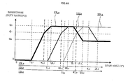
- FIG. 4A is a diagram representing an example of the relationship between the brightnesses of the sub headlight light sources and the lean angle of the motorcycle while the low beam light source is on.
- FIG. 4B is a diagram representing an example of the relationship between the brightnesses of the sub headlight light sources and the lean angle of the motorcycle while the high beam light source is on.
- the brightnesses Q 1 to Q 3 of the sub headlight light source satisfy the relationship Q 3 ⁇ Q 1 ⁇ Q 2 .
- the brightnesses of the sub headlight light sources 13La to 13Lc vary according to the lean angle in the manner described below.
- the sub headlight light sources 13La to 13Lc are off when the lean angle is at or above 0° and below the lower values TL 1 to TL 3 set for the sub headlight light sources 13La to 13Lc.
- the sub headlight light sources 13La to 13Lc turn on at brightnesses darker than brightness Q 1 when the lean angle is at or above the lower values TL 1 to TL 3 and below the reference values KL 1 to KL 3 set for the sub headlight light sources 13La to 13Lc.
- the brightnesses of the sub headlight light sources 13La to 13Lc continuously increase with increasing lean angles, and continuously decrease with decreasing lean angles.
- the sub headlight light sources 13La to 13Lc turn on at brightness Q 1 when the lean angle reaches the reference values KL 1 to KL 3 .
- the sub headlight light sources 13La to 13Lc are brighter than brightness Q 1 and darker than brightness Q 2 when the lean angle is above reference values KL 1 to KL 3 and below upper values UL 1 to UL 3 .
- the brightnesses of the sub headlight light sources 13La to 13Lc continuously increase with increasing lean angles, and continuously decrease with decreasing lean angles.
- the sub headlight light sources 13La to 13Lc turn on at brightness Q 2 when the lean angle reaches the upper values UL 1 to UL 3 .
- neither a specific value nor a prescribed value is set for the sub headlight light source 13Lc for which the largest reference value is set among the plurality of sub headlight light sources 13La to 13Lc.
- the sub headlight light source 13Lc with the largest reference value remains on at brightness Q 2 even after the lean angle has increased past the low-beam upper value UL 3 .
- the low-beam specific values IL 1 and IL 2 and the low-beam prescribed values JL 1 and JL 2 are set for the sub headlight light sources 13La and 13Lb other than the sub headlight light source 13Lc having the largest reference value.
- the sub headlight light sources 13La and 13Lb have brightness Q 2 while the lean angle is above the low-beam upper values UL 1 and UL 2 and at or below the low-beam specific values IL 1 and IL 2 .
- the sub headlight light sources 13La and 13Lb are darker than brightness Q 2 and brighter than brightness Q 3 while the lean angle is above the low-beam specific values IL 1 and IL 2 and below the low-beam prescribed values JL 1 and JL 2 .
- the brightnesses of the sub headlight light sources 13La and 13Lb continuously decrease with increasing lean angles, and continuously increase with decreasing lean angles.
- the sub headlight light sources 13La and 13Lb have brightness Q 3 while the lean angle is at or above the low-beam prescribed values JL 1 and JL 2 .
- the sub headlight light sources 13La to 13Lc are turned on in order with increasing lean angles of the motorcycle 10.
- the high-beam reference value KH n is smaller than the low-beam reference value KL n , as mentioned above. Accordingly, as represented in FIG. 4B , the sub headlight light sources 13La to 13Lc remain off while the motorcycle 10 is in the upright state and the high beam light source 11 H is on. As the lean angle increases, the sub headlight light sources 13La to 13Lc turn on at smaller lean angles than when the low beam light source 11L is on.
- the brightnesses of the sub headlight light sources 13La to 13Lc vary in the same fashion while the high beam light source 11H is on and while the low beam light source 11L is on, except that the brightnesses vary at different lean angles.
- the present embodiment has been described through the case where the specific value and the prescribed value are not set for one of the sub headlight light sources having the largest reference value.
- the present teaching is not limited to this example, and the specific value and the prescribed value may be set for all of the sub headlight light sources.
- one or more sub headlight light sources may be assigned with larger reference values (sub headlight light sources assigned with neither specific values nor prescribed values), and one or more sub headlight light sources may be assigned with smaller reference values (sub headlight light sources assigned with specific values and prescribed values).
- a duty ratio of the voltage sent to the sub headlight light source is used as an index of the brightness of the sub headlight light source.
- the index of the brightness of the sub headlight light source is not limited to this example in the present teaching.
- an applied voltage, an applied current, an illuminance at a predetermined distance from the light source, or a light source luminance may be used as an index of sub headlight light source brightness, and the relationships between the sub headlight light source brightnesses (Q 3 ⁇ Q 1 ⁇ Q 2 ) are established irrespective of the index used.
- the brightnesses Q 1 , Q 2 , and Q 3 are not particularly limited, and may be appropriately set, as needed.
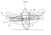
- FIG. 5 is a diagram schematically representing an example of the screen light distribution of each headlight light source of the motorcycle in the upright state.
- the motorcycle 10 is standing upright with respect to a flat ground G.
- the low beam light source 11L has an illumination range LB of a predetermined illuminance below the horizontal line H, and spreads sideways in a laterally uniform distribution in the width direction of the vehicle.
- the light axis A 0 of the low beam light source 11 L is below the horizontal line H in the illumination range LB.
- the cutoff line L 0 of the low beam light source 11L is at the upper edge of the illumination range LB, and spreads horizontally along the width direction of the vehicle above the light axis A 0 and below the horizontal line H.
- the illumination range LB of the low beam light source 11L covers both the left side and the right side relative to the width direction of the vehicle.
- the high beam light source 11H has an illumination range HB of a predetermined illuminance above the illumination range LB of a predetermined illuminance of the low beam light source 11L.
- the illumination range HB partially covers the space above the horizontal line H.
- the light axis A 1 of the high beam light source 11H is above the horizontal line H inside the illumination range HB.
- the sub headlight light sources 13La, 13Lb, and 13Lc have mutually overlapping illumination ranges SL 1 , SL 2 , and SL 3 arranged in order from the middle portion toward the upper left side relative to the width direction of the vehicle. Specifically, the illumination ranges SL 1 , SL 2 , and SL 3 of the sub headlight light sources 13La, 13Lb, and 13Lc are further upward as the low-beam reference values KL 1 , KL 2 , and KL 3 become larger.
- the light axes AL 1 to AL 3 of the sub headlight light sources 13La to 13Lc are inside of the illumination ranges SL 1 , SL 2 , and SL 3 , and are directed outward of the width direction of the vehicle in this order.
- the light axes AL 1 to AL 3 of the sub headlight light sources 13La to 13Lc are above the light axis A 0 of the low beam light source 11 L.
- cutoff lines LL 1 to LL 3 of the sub headlight light sources 13La to 13Lc are confined as a whole within the space above the horizontal line H.
- the tilt angles ⁇ 1 to ⁇ 3 of the cutoff lines LL 1 to LL 3 of the sub headlight light sources 13La to 13Lc are greater in this order.
- the tilt angles ⁇ 1 to ⁇ 3 of the cutoff lines LL 1 to LL 3 of the sub headlight light sources 13La to 13Lc are spaced apart from each other from 0° to ⁇ 1 , ⁇ 2 , and ⁇ 3 , in this order.
- the interval between 0° and ⁇ 1 is ⁇ 1 .
- the intervals ⁇ 1 , ⁇ 2 ', and ⁇ 3 ' satisfy the relationship ⁇ 1 > ⁇ 2 ' > ⁇ 3 ', where ⁇ 2 ' is the interval between ⁇ 2 and ⁇ 1 , and ⁇ 3 ' is the interval between ⁇ 3 and ⁇ 2 .
- sub headlight light sources 13Ra to 13Rc are identical to the sub headlight light sources 13La to 13Lc, except that these are mirror images of each other.
- the light axis is the straight line that passes the light source and the center of the maximum illuminance portion of the illumination light.
- the center of the maximum illuminance portion of the illumination light can be specified by providing illumination from the light source onto a screen disposed in front of the light source.
- This screen illuminance test can be performed according to the method specified by JIS D1619.
- the cutoff line and the illumination range of a predetermined illuminance also can be specified from the results of the screen illuminance test (for example, from an iso-illuminance distribution chart). Further, the cutoff line and the illumination range of a predetermined illuminance in planar view can be specified from a road surface light distribution converted from the result of the screen illuminance test.
- the conversion into a road surface light distribution can be performed by using a method known in the art. Specifically, a screen illuminance value may be converted into a road surface illuminance value by common plotting and geometric calculations. In this case, the following equation (I) may be used.
- Road surface illuminance Lx screen illuminance Lx ⁇ distance between D and F m / distance between D and E m 2 where D is the light source, E is a point on the road surface, and F is the intersection between a screen disposed between D and E and the line connecting D to E.
- the following describes the screen light distributions of the sub headlight light sources turning on with increasing lean angles to the left of the motorcycle 10, with reference to FIG. 6A to FIG. 7C .
- the low-beam reference values KL 1 , KL 2 , and KL 3 are lean angles ⁇ 1 , ⁇ 2 , and ⁇ 3 , respectively.
- the sub headlight light sources 13Ra to 13Rc that provide illumination on the opposite side of the lean direction of the motorcycle 10 are off.
- FIGS. 6A to 6C represent diagrams schematically illustrating examples of the screen light distribution of each sub headlight light source turning on with increasing lean angles of the motorcycle while the low beam light source is on.
- FIG. 6A represents screen light distributions upon the lean angle reaching the low-beam reference value KL 1 ( ⁇ 1 ).
- the low beam light source 11L and the sub headlight light source 13La are on, and the sub headlight light sources 13Lb and 13Lc are off.
- the cutoff line LL 1 of the sub headlight light source 13La is below the horizontal line H, and parallel to the horizontal line H.
- the angle created by the cutoff line LL 1 and the horizontal line H is 0°.
- the light axis A 0 and the light axis AL 1 are at the same level. Specifically, the height difference between the light axis A 0 and the light axis AL 1 is smaller than when the motorcycle is in the upright state ( FIG. 5 ).
- “same light axis level” also means “substantially the same light axis level”.
- FIG. 6B represents screen light distributions upon the lean angle reaching the low-beam reference value KL 2 ( ⁇ 2 ).
- the low beam light source 11L, and the sub headlight light sources 13La and 13Lb are on, and the sub headlight light source 13Lc is off.
- the cutoff line LL 2 of the sub headlight light source 13Lb is below the horizontal line H, and parallel to the horizontal line H.
- the angle created by the cutoff line LL 2 and the horizontal line H is 0°.
- the light axis A 0 and the light axis AL 2 are at the same level. Specifically, the height difference between the light axis A 0 and the light axis AL 2 is smaller than when the motorcycle is in the upright state ( FIG. 5 ).
- the outer edge of the illumination range SL 2 of the sub headlight light source 13Lb that turns on later is more outward (leftward of the width direction of the vehicle) than the outer edge of the illumination range SL 1 of the sub headlight light source 13La that turns on earlier.
- FIG. 6C represents screen light distributions upon the lean angle reaching the low-beam reference value KL 3 ( ⁇ 3 ).
- the low beam light source 11L, and the sub headlight light sources 13La, 13Lb, and 13Lc are on.
- the cutoff line LL 3 of the sub headlight light source 13Lc is below the horizontal line H, and parallel to the horizontal line H.
- the angle created between the cutoff line LL 3 and the horizontal line H is 0°.
- the light axis A 0 and the light axis AL 3 are at the same level. Specifically, the height difference between the light axis A 0 and the light axis AL 3 is smaller than when the motorcycle is in the upright state ( FIG. 5 ).
- the outer edge of the illumination range SL 3 of the sub headlight light source 13Lc that turns on later is more outward (leftward of the width direction of the vehicle) than the outer edges of the illumination ranges SL 1 and SL 2 of the sub headlight light sources 13La and 13Lb that turn on earlier.
- FIGS. 7A to 7C are diagrams schematically representing examples of the screen light distribution of each sub headlight light source turning on with increasing lean angles of the motorcycle while the high beam light source is on.
- FIG. 7A represents screen light distributions upon the lean angle reaching the high-beam reference value KH 1 ( ⁇ 1- ) (KH 1 ⁇ KL 1 , ⁇ 1- ⁇ ⁇ 1 ).
- the high beam light source 11H and the sub headlight light source 13La are on, and the sub headlight light sources 13Lb and 13Lc are off.
- the cutoff line LL 1 of the sub headlight light source 13La is above the horizontal line H.
- the cutoff line LL 1 tilts upward away from the vehicle relative to the width direction of the vehicle.
- the light axis A 0 and the light axis AL 1 are at the same level. Specifically, the height difference between the light axis A 0 and the light axis AL 1 is smaller than when the motorcycle is in the upright state ( FIG. 5 ).
- FIG. 7B represents screen light distributions upon the lean angle reaching the high-beam reference value KH 2 ( ⁇ 2- ) (KH 2 ⁇ KL 2 , ⁇ 2- ⁇ ⁇ 2 ).
- the high beam light source 11H, and the sub headlight light sources 13La and 13Lb are on, and the sub headlight light source 13Lc is off.
- the cutoff line LL 2 of the sub headlight light source 13Lb is above the horizontal line H.
- the cutoff line LL 2 tilts upward away from the vehicle relative to the width direction of the vehicle.
- the light axis A 0 and the light axis AL 2 are at the same level. Specifically, the height difference between the light axis A 0 and the light axis AL 2 is smaller than when the motorcycle is in the upright state ( FIG. 5 ).
- the outer edge of the illumination range SL 2 of the sub headlight light source 13Lb that turns on later is more outward (leftward of the width direction of the vehicle) than the outer edge of the illumination range SL 1 of the sub headlight light source 13La that turns on earlier.
- FIG. 7C represents screen light distributions upon the lean angle reaching the high-beam reference value KH 3 ( ⁇ 3- ) (KH 3 ⁇ KL 3 , ⁇ 3- ⁇ ⁇ 3 ).
- the high beam light source 11H, and the sub headlight light sources 13La, 13Lb, and 13Lc are on.
- the cutoff line LL 3 of the sub headlight light source 13Lc is above the horizontal line H.
- the cutoff line LL 3 tilts upward away from the vehicle relative to the width direction of the vehicle.
- the light axis A 0 and the light axis AL 3 are at the same level. Specifically, the height difference between the light axis A 0 and the light axis AL 3 is smaller than when the motorcycle is in the upright state ( FIG. 5 ).
- the outer edge of the illumination range SL 3 of the sub headlight light source 13Lc that turns on later is more outward (leftward of the width direction of the vehicle) than the outer edges of the illumination ranges SL 1 and SL 2 of the sub headlight light sources 13La and 13Lb that turn on earlier.
- the sub-headlight unit 13L of the present embodiment includes the sub headlight light sources 13La to 13Lc, separately provided from the low beam light source 11L and the high beam light source 11H, and the sub headlight light sources 13La to 13Lc turn on according to lean angle. This makes it possible to suitably adjust the sub headlight light sources 13La to 13Lc and the high beam light source 11H to have light distributions that are more in conformity with the intended roles of these light sources, and to reduce illumination in unnecessary spaces.
- the sub headlight light sources 13La to 13Lc separately provided from the low beam light source 11L and the high beam light source 11H, turn on according to the lean angle of the motorcycle 10, and accordingly have a shorter on-time than the low beam light source 11L and the high beam light source 11H. This makes it possible to reduce the size of the heat radiation mechanism, and to limit the size of the headlight installation space. Further, because the sub headlight light sources 13La to 13Lc are used while the low beam light source 11L and/or the high beam light source 11H are on, it is possible to limit the number of sub headlight light sources, and to suppress size increase.
- the sub headlight light sources 13La to 13Lc can provide more distant illumination when the lean angle reaches the high-beam reference value KH n than when the lean angle reaches the low-beam reference value KL n .
- the sub-headlight unit 13L can thus desirably illuminate inside of a curve, regardless of whether the low beam light source 11L or the high beam light source 11H is on, while suppressing a size increase.
- the cutoff lines LL 1 to LL 3 of the sub headlight light sources 13La to 13Lc are below the horizontal line H when the lean angle of the motorcycle 10 is at the low-beam reference value KL n , and are at least partially above the horizontal line H when the lean angle of the motorcycle 10 is at the high-beam reference value KH n .
- the sub headlight light sources 13La to 13Lc can suppress glare to other road users while the low beam light source 11L is on, and provide distant illumination while the high beam light source 11H is on.
- the cutoff lines LL 1 , LL 2 , and LL 3 of the sub headlight light sources 13La, 13Lb, and 13Lc are horizontal while the low beam light source 11L is on.
- the cutoff lines LL 1 , LL 2 , and LL 3 of the sub headlight light sources 13La, 13Lb, and 13Lc tilt while the high beam light source 11H is on.
- the angle created by the cutoff lines LL 1 , LL 2 , and LL 3 and the horizontal line H while the sub headlight light sources 13La, 13Lb, and 13Lc are on is smaller while the low beam light source 11L is on (0°) than while the high beam light source 11H is on.
- the sub headlight light sources 13La to 13Lc and 13Ra to 13Rc can suppress glare to other road users while the low beam light source 11L is on, and provide distant illumination while the high beam light source 11H is on.
- the sub headlight light sources 13La to 13Lc remain off while the motorcycle 10 is in the upright state, regardless of whether the low beam light source 11L or the high beam light source 11H is on. In this way, the on-time of the sub headlight light sources 13La to 13Lc can be reduced, despite that the sub headlight light sources 13La to 13Lc turn on according to lean angle.
- the height differences between the light axes AL 1 to AL 3 of the sub headlight light sources 13La to 13Lc and the light axis A 1 of the high beam light source 11H are smaller (see FIGS. 7A to 7C ) when the lean angle of the motorcycle 10 is at the high-beam reference value KH n than when the sub headlight light sources 13La to 13Lc are turned on in the upright state of the motorcycle 10 (see FIG. 5 ).
- the low-beam reference values satisfy KL n ⁇ KL n+1
- the high-beam reference values satisfy KH n ⁇ KH n+1 .
- the illumination ranges SL 1 to SL 3 of the sub headlight light sources 13La to 13Lc do not appear much different to the operator while the low beam light source 11L is on and while the high beam light source 11H is on, and appear more natural to the operator.
- the positions of the illumination ranges SL 1 to SL 3 of the sub headlight light sources 13La to 13Lc are further upward as the low-beam reference values KL 1 to KL 3 of the sub headlight light sources 13La to 13Lc become larger in the upright state of the motorcycle 10.
- the height differences of the illumination ranges SL 1 to SL 3 of the sub headlight light sources 13La to 13Lc can be made smaller while the low beam light source 11L and/or the high beam light source 11H are on.
- the outer edge of the illumination range of a predetermined illuminance of the sub headlight light source that turns on later is more outward (relative to the width direction of the vehicle) than the outer edge of the illumination range of a predetermined illuminance of the sub headlight light source that turns on earlier in the plurality of sub headlight light sources 13La to 13Lc that turn on with increasing lean angles of the motorcycle 10, regardless of whether the low beam light source 11L or the high beam light source 11H is on (see FIGS. 6B and 6C , and FIGS. 7B and 7C ). It is therefore possible to appropriately illuminate the target view of the operator passing a curve, regardless of whether the low beam light source 11L or the high beam light source 11H is on.
- the present embodiment has been described through the case where the lower value, the reference value, the upper value, the specific value, and the prescribed value are set as the low-beam and high-beam variables respectively for the sub headlight light sources 13La to 13Lc.
- the present teaching is not limited to this example, provided that at least the reference values are set.
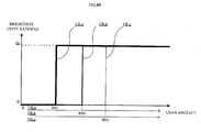
- FIG. 8A is a diagram representing another example of the relationship between the brightnesses of the sub headlight light sources and the lean angle of the motorcycle while the low beam light source is on.
- FIG. 8B is a diagram representing another example of the relationship between the brightnesses of the sub headlight light sources and the lean angle of the motorcycle while the high beam light source is on.
- the sub headlight light sources 13La to 13Lc are off while the lean angle of the motorcycle 10 is below the low-beam reference values KL 1 to KL 3 , and are on while the lean angle is at or above the low-beam reference values KL 1 to KL 3 .
- the sub headlight light sources 13La to 13Lc are off while the lean angle of the motorcycle 10 is below the high-beam reference values KH 1 to KH 3 , and are on while the lean angle is at or above the high-beam reference values KH 1 to KH 3 .
- the foregoing embodiment described the case where three sub headlight light sources provide illumination on one side of the width direction of the vehicle.
- the number of sub headlight light sources that provide illumination on one side of the width direction of the vehicle is not particularly limited, and only a single sub headlight light source, or more than one sub headlight light source may be provided to provide illumination one side of the width direction of the vehicle.
- the sub headlight light sources 13La to 13Lc, 13Ra to 13Rc are LEDs, and the controller 20 controls (modulates) the brightness by adjusting the duty ratio by pulse width modulation (PWM).
- PWM pulse width modulation
- the method used to modulate the sub headlight light sources is not particularly limited, and, for example, the current or voltage sent to the sub headlight light sources may be controlled.
- a single sub headlight light source may be realized by a plurality of light sources of different brightnesses. In this case, these light sources may be switchably turned on to modulate the sub headlight light source.
- a single sub headlight light source includes three light sources of different brightnesses (for example, light sources that turn on at Q 1 , Q 2 , and Q 3 ; see FIGS. 4A and 4B )
- the brightnesses of the light sources can be controlled by switchably turning on the light sources.
- the sub headlight light source may be modulated by turning on the light sources in different numbers or in different combinations.
- the light sources may have the same or different brightnesses.
- the motorcycle 10 of the present embodiment includes the sub-headlight units 13L and 13R disposed on each side of the width direction of the vehicle.
- the present teaching is not limited to this example.
- a single sub-headlight unit may be realized as the integral unit of the sub-headlight units 13L and 13R disposed on each side of the width direction of the vehicle.
- the sub-headlight unit may be a physically integral unit, or the sub headlight light sources in the sub-headlight unit may be physically separated.
- the sub-headlight units 13L and 13R are separately provided from the main headlight light source 11.
- the present teaching is not limited to this example, and the sub-headlight units may be integrally provided with the main head light source.
- the pair of left and right sub-headlight units 13L and 13R, the low beam light source 11L, and the high beam light source 11H form the headlight unit according to the present teaching.
- the lean angle sensor 22 and the vehicle speed sensor 23 correspond to the detection unit that detects a variable used to find the lean angle of the motorcycle 10.
- the detection unit includes the lean angle sensor 22 and the vehicle speed sensor 23.
- the present teaching is not limited to this example, and, for example, the detection unit may include only the lean angle sensor 22, and not the vehicle speed sensor 23.
- the controller 20 corresponds to the control unit of the present teaching.
- the hardware configuration is not limited to this example in the present teaching.
- the control unit determines whether or not the lean angle of the motorcycle 10 has reached the reference value (low-beam reference value or high-beam reference value), using the variables detected by the detection unit.
- control unit is not necessarily required to calculate the lean angle, and the specific processing performed by the control unit is not particularly limited.
- data of a table that correlates the angular velocity (roll rate) and vehicle speed to the result of whether or not the lean angle has reached the reference value may be stored in the memory of the controller 20 provided as the control unit.
- the control unit can refer to the table based on angular velocity and vehicle speed to determine whether or not the lean angle has reached the reference value, without calculating the lean angle.
- the lean angle is the tilt angle of the vehicle leaning into a curve, relative to the upright state (vertical direction).
- the present teaching is not limited to this example, and the lean angle of the vehicle leaning into a curve may be a tilt angle relative to the direction perpendicular to the road surface.
- the tilt angle may be measured by using methods and devices known in the art.
- the sub-headlight unit is described as being separately provided from the control unit (controller 20) and the detection unit (lean angle sensor 22 and vehicle speed sensor 23).
- the sub-headlight unit may include at least one of the control unit, a communication unit, and the detection unit.
- the sub headlight light source may be configured so that the function of lighting up according to lean angle is manually switched ON/OFF. Note here that even in this case the sub headlight light source turns on according to lean angle, not manually. On the other hand, the ON/OFF of the flashers are manually switched. This distinguishes the sub headlight light source from the flashers.
- the sub headlight light source may be adapted to receive manually input ON/OFF instructions.
- the sub headlight light source turns on according to lean angle in the absence of the instructions, whereas, in the presence of the instructions, the sub headlight light source is turned on and off according to the instructions. Even in this case, the sub headlight light source still functions to turn on according to lean angle, and distinguishes itself from the flashers.
- "turning on" the sub headlight light source according to lean angle is not necessarily limited to directly bringing the sub headlight light source to the ON state from the OFF state according to lean angle, and may include gradually bringing the sub headlight light source to the ON state from the OFF state according to lean angle. Further, gradually bringing the sub headlight light source to the ON state from the OFF state according to lean angle includes both continuously bringing the sub headlight light source to the ON state from the OFF state, and bringing the sub headlight light source to the ON state from the OFF state in a stepwise fashion. Further, the ON state is not limited to the full ON state at the rated output, and may include the dim ON state in which the output is controlled below the output in the full ON state.
- the output in the full ON state may exceed the rated output (for example, the light may be turned on at the maximum output).
- the output in the dim ON state exceeds the OFF-state output.
- Turning on the sub headlight light source according to lean angle may include turning on at a predetermined brightness brighter than in the OFF state according to lean angle.
- "turning on” the sub headlight light source according to lean angle may include the following (i) to (iv), and is not limited to (i).
- turning on the sub headlight light source according to lean angle may include continuously or gradually varying the duty ratio of the sub headlight light source from zero to higher values (above 0) according to lean angle.
- the present embodiment has been described through the case where the sub headlight light source turns on according to lean angle.
- the sub headlight light source turns on according to lean angle, because the sub headlight light source mainly serves to provide light for the visibility of the operator of the vehicle.
- the sub headlight light source is not necessarily required to turn on according to lean angle under bright conditions such as in daytime.
- the embodiment discloses the following configurations.
- the sub headlight light source is separately provided from the low beam light source and the high beam light source provided as main headlights, and the sub headlight light source turns on according to lean angle.
- the sub headlight light source provides illumination forward and outward of the width direction of the vehicle on one side of the vehicle, and has a different role from the high beam light source intended to provide illumination forward in front of the vehicle (the illumination directions of light are different).
- the respective light distributions of the sub headlight light source and the high beam light source can be suitably adjusted more in conformity with the intended roles of these light sources, and the light can be suppressed from illuminating unnecessary spaces. This makes it possible to suppress an increase in power consumption, and in the size of the engine, the battery, or the like.
- the sub headlight light source separately provided from the low beam light source and the high beam light source, turns on according to the lean angle of the vehicle, and thus the on-time of the sub headlight light source is shorter than the on-times of the low beam light source and the high beam light source. This makes it possible to reduce the size of the heat radiation mechanism, and to suppress an increase in the size of the headlight installation space. Further, because the sub headlight light source is used while the low beam light source and/or the high beam light source are on, it is possible to limit the number of sub headlight light sources, and to suppress size increase.
- the sub headlight light source can provide more distant illumination when the lean angle reaches the high-beam reference value than when the lean angle reaches the low-beam reference value. This makes it possible to make the illumination range of the sub headlight light source suitable for the high-beam illumination while also providing a suitable sub headlight light source illumination range for the low-beam illumination, without separately providing a sub headlight light source for use while the low beam light source is on, and a sub headlight light source for use while the high beam light source is on.
- sub headlight light source has a cutoff line below the horizontal line of the sub headlight light source upon the lean angle of the vehicle reaching the low-beam reference value, and wherein the sub headlight light source has a cutoff line at least partially above the horizontal line of the sub headlight light source upon the lean angle of the vehicle reaching the high-beam reference value.
- glare to other road users can be suppressed while the low beam light source is on, and distant illumination can be provided while the high beam light source is on. In this way, it is possible to more desirably illuminate inside of a curve while the low beam and/or the high beam are on.
- sub headlight light source is off in the upright state of the vehicle regardless of whether the low beam light source or the high beam light source is on.
- the on-time of the sub headlight light source can be reduced while allowing the sub headlight light source to be turned on according to lean angle. In this way, it is possible to more effectively suppress an increase in power consumption, and thus a size increase of the heat radiation mechanism, the engine, the battery, or the like can be effectively suppressed.
- the height difference between the center of a maximum illuminance portion of the illumination light from the sub headlight light source and the center of a maximum illuminance portion of the illumination light from the high beam light source is smaller when the lean angle of the vehicle is at the high-beam reference value than when the sub headlight light source is on in the upright state of the vehicle.
- the configuration of (5) more distant and effective illumination can be provided, and the light can be suppressed from unnecessarily illuminating the space above the horizontal line while the high beam light source is on. In this way, it is possible to desirably illuminate inside of a curve while the high beam light source is on, while providing desirable illumination inside of the curve while the low beam light source is on.
- the sub-headlight unit comprises a plurality of the sub headlight light sources, the low-beam reference value and the high-beam reference value being set for each of the plurality of sub headlight light sources, and the low-beam reference value being different for the plurality of sub headlight light sources, the plurality of sub headlight light sources being turned on in order from the sub headlight light sources having the smaller low-beam reference values as the lean angle to the one side of the vehicle increases while the low beam light source is on, and the high-beam reference value of the sub headlight light source that turns on later being equal to or greater than the high-beam reference value of the sub headlight light source that turns on earlier in the turn-on sequence of the plurality of sub headlight light sources while the low beam light source is on.
- the plurality of sub headlight light sources that turns on while the high beam light source is on turns on in the same sequence as the turn-on sequence of the plurality of sub headlight light sources that turns on while the low beam light source is on.
- the sub headlight light source that turns on later (for example, the sub headlight light source that turns on second) in the plurality of sub headlight light sources while the low beam light source is on does not turn on before the sub headlight light source that turns on earlier (for example, the sub headlight light source that turns on first) in the plurality of sub headlight light sources while the high beam light source is on.
- the difference between the way the illumination ranges of the sub headlight light sources appear while the low beam light source is on and the way the illumination ranges of the sub headlight light sources appear while the high beam light source is on can be made smaller for the operator. This makes it possible to suppress the strangeness that might be felt by the operator in the illumination ranges of the sub headlight sources, and it is possible to more desirably illuminate inside of a curve, regardless of whether the low beam or the high beam is on.
- the vertical moving range of the sub headlight light source from when the vehicle is in the upright state to when the lean angle of the vehicle reaches the low-beam reference value becomes larger for the sub headlight light sources having larger low-beam reference values.
- the height difference that occurs in the on-illumination range of the sub headlight light source while the low beam light source is on can be reduced, because the illumination range of the sub headlight light sources is positioned further upward for the sub headlight light sources having larger low-beam reference values.
- the operator does not notice a large difference in the on-illumination range of each sub headlight light source.
- the high-beam reference value set for each sub headlight light source is smaller than the low-beam reference value set for the same sub headlight light source, and the high-beam reference value of the sub headlight light source that turns on later is equal to or greater than the high-beam reference value of the sub headlight light source that turns on earlier while the low beam light source is on.
- This also makes it possible to reduce the height difference that occurs in the on-illumination range of the sub headlight light source while the high beam light source is on.
- the operator does not notice a large difference in the on-illumination range of each sub headlight light source.
- the illumination ranges of the sub headlight light sources do not appear much different to the operator, and the light can more desirably illuminate inside of a curve, regardless of whether the low beam or the high beam is on.
- the sub headlight light source that turns on later with increasing lean angles of the vehicle has an illumination range of a predetermined illuminance whose outer edge is more outward relative to the width direction of the vehicle than the outer edge of the illumination range of a predetermined illuminance of the sub headlight light source that turns on earlier when the plurality of sub headlight light sources turns on with increasing lean angles of the vehicle, regardless of whether the low beam light source or the high beam light source is on.
- the operator of a vehicle passing a curve tends to look at further inside of the curve as the lean angle of the vehicle increases.
- the sub headlight light source that turns on later has an illumination range of a predetermined illuminance whose outer edge is more outward relative to the width direction of the vehicle than the outer edge of the illumination range of a predetermined illuminance of the sub headlight light source that turns on earlier, regardless of whether the low beam light source or the high beam light source is on.
- the light can more desirably illuminate the target view of the operator passing a curve, regardless of whether the low beam light source or the high beam light source is on.
- the headlight unit comprising the sub-headlight unit of any one of (1) to (8) in a pair, and the low beam light source and the high beam light source, wherein one of the two sub-headlight units provides illumination forward and outward of the width direction of the vehicle on the left side of the vehicle, and the other sub-headlight unit provides illumination forward and outward of the width direction of the vehicle on the right side of the vehicle.
- illumination can be desirably provided inside of a curve regardless of whether the low beam or the high beam is on, while suppressing a size increase.
- the headlight system comprising:
- an AFS Adaptive Front-Lighting System
- illumination can be desirably provided inside of a curve regardless of whether the low beam or the high beam is on, while suppressing a size increase.
Claims (17)
- Unité de sous-phare pour un véhicule se penchant dans les virages en s'inclinant sur une courbe, l'unité de sous-phare (13L, 13R) comprenant :- au moins une source lumineuse de sous-phare (13La à 13Lc, 13Ra à 13Rc) fournissant une lumière d'éclairage vers l'avant et l'extérieur suivant la direction d'une largeur du véhicule sur un côté suivant la direction d'une largeur du véhicule ; et- une unité de commande (20) adaptée à commander la source lumineuse de sous-phare (13La à 13Lc, 13Ra à 13Rc) suivant un angle d'inclinaison du véhicule,- caractérisée en ce que l'unité de commande (20) est adaptée à allumer la source lumineuse de sous-phare (13La à 13Lc, 13Ra à 13Rc) lorsque l'angle d'inclinaison du véhicule se penchant vers le côté suivant la direction d'une largeur du véhicule atteint une valeur de référence de faisceau bas tandis qu'une source lumineuse de faisceau bas (11L) du véhicule est allumée ; et- l'unité de commande (20) est adaptée à allumer la source lumineuse de sous-phare (13La à 13Lc, 13Ra à 13Rc) lorsque l'angle d'inclinaison du véhicule se penchant vers le côté suivant la direction d'une largeur du véhicule atteint une valeur de référence de faisceau haut, plus petite que la valeur de référence de faisceau bas, tandis qu'une source lumineuse de faisceau haut (11H) du véhicule est allumée.
- Unité de sous-phare selon la revendication 1, caractérisée en ce que la source lumineuse de sous-phare (13La à 13Lc, 13Ra à 13Rc) comporte une ligne de coupure au-dessous d'une ligne horizontale de la source lumineuse de sous-phare (13La à 13Lc, 13Ra à 13Rc) lorsque l'angle d'inclinaison du véhicule atteint la valeur de référence de faisceau bas, et- dans laquelle la source lumineuse de sous-phare (13La à 13Lc, 13Ra à 13Rc) comporte une ligne de coupure au moins partiellement au-dessus de la ligne horizontale de la source lumineuse de sous-phare (13La à 13Lc, 13Ra à 13Rc) lorsque l'angle d'inclinaison du véhicule atteint la valeur de référence de faisceau haut.
- Unité de sous-phare selon les revendications 1 ou 2, caractérisée en ce que l'angle créé par une ligne de coupure et une ligne horizontale de la source lumineuse de sous-phare (13La à 13Lc, 13Ra à 13Rc) est plus petit lorsque l'angle d'inclinaison du véhicule est à la valeur de référence de faisceau bas lorsque l'angle d'inclinaison du véhicule est à la valeur de référence de faisceau haut.
- Unité de sous-phare selon l'une quelconque des revendications 1 à 3, caractérisée en ce que l'unité de commande (20) est adaptée à éteindre la source lumineuse de sous-phare (13La à 13Lc, 13Ra à 13Rc) à l'état droit du véhicule indépendamment du fait que la source lumineuse de faisceau bas (11L) ou la source lumineuse de faisceau haut (11H) soit allumée ou non.
- Unité de sous-phare selon l'une quelconque des revendications 1 à 4, caractérisée en ce qu'une différence de hauteur entre un centre d'une partie de luminance maximale de la lumière d'éclairage de la source lumineuse de sous-phare (13La à 13Lc, 13Ra à 13Rc) et un centre d'une partie de luminance maximale de la lumière d'éclairage de la source lumineuse de faisceau haut (11H) est plus petite lorsque l'angle d'inclinaison du véhicule est à la valeur de référence de faisceau haut que lorsque la source lumineuse de sous-phare (13La à 13Lc, 13Ra à 13Rc) est allumée à l'état droit du véhicule.
- Unité de sous-phare selon la revendication 1, caractérisée en ce que l'unité de sous-phare (13L, 13R) comprend une pluralité de sources lumineuses de sous-phare (13La à 13Lc, 13Ra à 13Rc) ;- la valeur de référence de faisceau bas et la valeur de référence de faisceau haut étant fixées pour chaque source de la pluralité de sources lumineuses de sous-phare (13La à 13Lc, 13Ra à 13Rc) et la valeur de référence de faisceau bas étant différente pour la pluralité de sources lumineuses de sous-phare (13La à 13Lc, 13Ra à 13Rc) ;- l'unité de commande (20) est adaptée à allumer la pluralité de sources lumineuses de sous-phare (13La à 13Lc, 13Ra à 13Rc) dans un ordre à partir des sources lumineuses de sous-phare (13La à 13Lc, 13Ra à 13Rc) ayant les valeurs de référence de faisceau bas plus petites à mesure qu'augmente l'angle d'inclinaison vers le côté du véhicule tandis que la source lumineuse de faisceau bas (11L) est allumée ; et- la valeur de référence de faisceau haut de la source lumineuse de sous-phare (13La à 13Lc, 13Ra à 13Rc) s'allumant plus tard étant supérieure ou égale à la valeur de référence de faisceau haut de la source lumineuse de sous-phare (13La à 13Lc, 13Ra à 13Rc) s'allumant plus tôt dans la séquence d'allumage de la pluralité de sources lumineuses de sous-phare (13La à 13Lc, 13Ra à 13Rc) tandis que la source lumineuse de faisceau bas (11L) est allumée.
- Unité de sous-phare selon la revendication 6, caractérisée en ce que les sources lumineuses de sous-phare (13La à 13Lc, 13Ra à 13Rc) ayant les valeurs de référence de faisceau bas plus grandes ont des portées d'éclairage positionnées davantage vers le haut du véhicule à l'état droit du véhicule.
- Unité de sous-phare selon les revendications 6 ou 7, caractérisée en ce que la source lumineuse de sous-phare (13La à 13Lc, 13Ra à 13Rc) s'allumant plus tard à mesure qu'augmentent les angles d'inclinaison du véhicule a une portée d'éclairage d'une luminance prédéterminée dont le bord extérieur est davantage vers l'extérieur relativement à la direction d'une largeur du véhicule que le bord extérieur de la portée d'éclairage d'une luminance prédéterminée de la source lumineuse de sous-phare (13La à 13Lc, 13Ra à 13Rc) s'allumant plus tôt lorsque la pluralité de sources lumineuses de sous-phare (13La à 13Lc, 13Ra à 13Rc) s'allume à mesure qu'augmentent les angles d'inclinaison du véhicule, indépendamment du fait que la source lumineuse de faisceau bas (11L) ou la source lumineuse de faisceau haut (11H) soit allumée ou non.
- Unité de phare pour un véhicule se penchant dans les virages en s'inclinant sur une courbe, l'unité de phare comprenant l'unité de sous-phare (13L, 13R) selon l'une quelconque des revendications 1 à 8 en une paire et la source lumineuse de faisceau bas (11L) et la source lumineuse de faisceau haut (11H),- dans laquelle une (13L) des deux unités de sous-phare fournit une lumière d'éclairage vers l'avant et l'extérieur suivant la direction d'une largeur du véhicule sur le côté gauche du véhicule et l'autre (13R) unité de sous-phare fournit une lumière d'éclairage vers l'avant et l'extérieur suivant la direction d'une largeur du véhicule sur le côté droit du véhicule.
- Système de phare pour un véhicule se penchant dans les virages en s'inclinant sur une courbe, le système de phare comprenant :- l'unité de phare selon la revendication 9 ;- une unité de détection détectant une variable utilisée pour trouver l'angle d'inclinaison du véhicule ; et- l'unité de commande (20) est adaptée à allumer la source lumineuse de sous-phare (13La à 13Lc, 13Ra à 13Rc) suivant l'angle d'inclinaison du véhicule trouvé en utilisant le résultat de la détection par l'unité de détection.
- Véhicule se penchant dans les virages en s'inclinant sur une courbe, dans lequel le véhicule comprend le système de phare selon la revendication 10.
- Procédé de commande d'une unité de sous-phare pour un véhicule se penchant dans les virages en s'inclinant sur une courbe, consistant à :- fournir une lumière d'éclairage vers l'avant et l'extérieur suivant la direction d'une largeur du véhicule sur un côté suivant la direction d'une largeur du véhicule par au moins une source lumineuse de sous-phare (13La à 13Lc, 13Ra à 13Rc) suivant un angle d'inclinaison du véhicule,- caractérisé par les étapes consistant à :- allumer la source lumineuse de sous-phare (13La à 13Lc, 13Ra à 13Rc) lorsque l'angle d'inclinaison du véhicule se penchant vers le côté suivant la direction d'une largeur du véhicule atteint une valeur de référence de faisceau bas tandis qu'une source lumineuse de faisceau bas (11L) du véhicule est allumée ; et- allumer la source lumineuse de sous-phare (13La à 13Lc, 13Ra à 13Rc) lorsque l'angle d'inclinaison du véhicule se penchant vers le côté suivant la direction d'une largeur du véhicule atteint une valeur de référence de faisceau haut, plus petite que la valeur de référence de faisceau bas, tandis qu'une source lumineuse de faisceau haut (11H) du véhicule est allumée.
- Procédé de commande d'une unité de sous-phare selon la revendication 12, caractérisé par les étapes consistant à :- fixer une ligne de coupure de la source lumineuse de sous-phare (13La à 13Lc, 13Ra à 13Rc) au-dessous de la ligne horizontale de la source lumineuse de sous-phare (13La à 13Lc, 13Ra à 13Rc) lorsque l'angle d'inclinaison du véhicule atteint la valeur de référence de faisceau bas ;- fixer une ligne de coupure de la source lumineuse de sous-phare (13La à 13Lc, 13Ra à 13Rc) au moins partiellement au-dessus de la ligne horizontale de la source lumineuse de sous-phare (13La à 13Lc, 13Ra à 13Rc) lorsque l'angle d'inclinaison du véhicule atteint la valeur de référence de faisceau haut.
- Procédé de commande d'une unité de sous-phare selon les revendications 12 ou 13, caractérisé en ce que l'angle formé par une ligne de coupure et une ligne horizontale de la source lumineuse de sous-phare (13La à 13Lc, 13Ra à 13Rc) est fixé pour être plus petit lorsque l'angle d'inclinaison du véhicule est à la valeur de référence de faisceau haut.
- Procédé de commande d'une unité de sous-phare selon l'une quelconque des revendications 12 à 14, caractérisé par l'étape consistant à :- éteindre la source lumineuse de sous-phare (13La à 13Lc, 13Ra à 13Rc) à l'état droit du véhicule indépendamment du fait que la source lumineuse de faisceau bas (11L) ou la source lumineuse de faisceau haut (11H) soit allumée ou non.
- Procédé de commande d'une unité de sous-phare selon l'une quelconque des revendications 12 à 15, caractérisé en ce qu'une différence de hauteur entre un centre d'une partie de luminance maximale de la lumière d'éclairage de la source lumineuse de sous-phare (13La à 13Lc, 13Ra à 13Rc) et un centre d'une partie de luminance maximale de la lumière d'éclairage de la source lumineuse de faisceau haut (11H) est fixée plus petite lorsque l'angle d'inclinaison du véhicule est à la valeur de référence de faisceau haut que lorsque la source lumineuse de sous-phare (13La à 13Lc, 13Ra à 13Rc) est allumée à l'état droit du véhicule.
- Procédé de commande d'une unité de sous-phare selon l'une quelconque des revendications 12 à 16, caractérisé en ce que l'unité de sous-phare comprend une pluralité de sources lumineuses de sous-phare (13La à 13Lc, 13Ra à 13Rc), le procédé comprenant en outre les étapes consistant à :- fixer la valeur de référence de faisceau bas et la valeur de référence de faisceau haut pour chaque source de la pluralité de sources lumineuses de sous-phare (13La à 13Lc, 13Ra à 13Rc), la valeur de référence de faisceau bas étant différente pour la pluralité de sources lumineuses de sous-phare (13La à 13Lc, 13Ra à 13Rc) ;- allumer la pluralité de sources lumineuses de sous-phare (13La à 13Lc, 13Ra à 13Rc) dans un ordre à partir des sources lumineuses de sous-phare (13La à 13Lc, 13Ra à 13Rc) ayant les valeurs de référence de faisceau bas plus petites à mesure qu'augmente l'angle d'inclinaison vers le côté du véhicule tandis que la source lumineuse de faisceau bas (11L) est allumée ; et- fixer la valeur de référence de faisceau haut de la source lumineuse de sous-phare (13La à 13Lc, 13Ra à 13Rc) s'allumant plus tard pour qu'elle soit supérieure ou égale à la valeur de référence de faisceau haut de la source lumineuse de sous-phare (13La à 13Lc, 13Ra à 13Rc) s'allumant plus tôt dans la séquence d'allumage de la pluralité de sources lumineuses de sous-phare (13La à 13Lc, 13Ra à 13Rc) tandis que la source lumineuse de faisceau bas (11L) est allumée.
Applications Claiming Priority (1)
| Application Number | Priority Date | Filing Date | Title |
|---|---|---|---|
| JP2012137040A JP2014000875A (ja) | 2012-06-18 | 2012-06-18 | リーン姿勢で旋回する車両用のサブヘッドライトユニット、ヘッドライトユニット及びヘッドライトシステム、並びにリーン姿勢で旋回する車両 |
Publications (2)
| Publication Number | Publication Date |
|---|---|
| EP2676872A1 EP2676872A1 (fr) | 2013-12-25 |
| EP2676872B1 true EP2676872B1 (fr) | 2015-01-07 |
Family
ID=47227600
Family Applications (1)
| Application Number | Title | Priority Date | Filing Date |
|---|---|---|---|
| EP12192580.4A Active EP2676872B1 (fr) | 2012-06-18 | 2012-11-14 | Sous-bloc optique, bloc optique, système de bloc optique pour véhicule qui penche dans les virages, véhicule qui penche dans les virages et procédé pour commander le sous-bloc optique pour véhicule qui penche dans les virages |
Country Status (2)
| Country | Link |
|---|---|
| EP (1) | EP2676872B1 (fr) |
| JP (1) | JP2014000875A (fr) |
Cited By (1)
| Publication number | Priority date | Publication date | Assignee | Title |
|---|---|---|---|---|
| EP3802298B1 (fr) * | 2018-06-05 | 2022-12-21 | Indian Motorcycle International, LLC | Système d'éclairage adaptatif pour vehicle à deux-roues |
Families Citing this family (7)
| Publication number | Priority date | Publication date | Assignee | Title |
|---|---|---|---|---|
| US10023103B2 (en) | 2013-09-13 | 2018-07-17 | J.W. Speaker, Corporation | Systems and methods for illumination control and distribution during a vehicle bank |
| JP5946502B2 (ja) * | 2014-09-24 | 2016-07-06 | ヤマハ発動機株式会社 | ヘッドランプシステムおよび鞍乗り型車両 |
| JP6761244B2 (ja) * | 2015-12-28 | 2020-09-23 | 川崎重工業株式会社 | 乗物 |
| WO2018168249A1 (fr) * | 2017-03-14 | 2018-09-20 | ヤマハ発動機株式会社 | Appareil de phare de véhicule incliné et véhicule incliné |
| US11027790B2 (en) * | 2018-06-05 | 2021-06-08 | Indian Motorcycle International, LLC | Adaptive lighting system |
| US11465705B2 (en) | 2018-06-05 | 2022-10-11 | Indian Motorcycle International, LLC | Adaptive lighting system |
| ES2900699A1 (es) * | 2020-09-17 | 2022-03-17 | Cecotec Res And Development Sl | Sistema de iluminación adaptativo y método asociado para vehículo de movilidad personal |
Family Cites Families (6)
| Publication number | Priority date | Publication date | Assignee | Title |
|---|---|---|---|---|
| US5426571A (en) * | 1993-03-11 | 1995-06-20 | Jones; Jerry | Motorcycle headlight aiming device |
| US7445364B2 (en) * | 2001-01-19 | 2008-11-04 | Stephan Gropp | Headlight unit for single-track two-wheeled vehicles |
| JP4782051B2 (ja) | 2007-03-15 | 2011-09-28 | 株式会社小糸製作所 | 二輪車用前照灯 |
| NL1034984C2 (nl) * | 2008-01-31 | 2009-08-03 | Baggermans Holding B V | Koplamp voor een motorfiets alsmede een motorfiets voorzien van een dergelijke koplamp. |
| JP5134527B2 (ja) * | 2008-12-25 | 2013-01-30 | 川崎重工業株式会社 | 自動二輪車のバンク角検知装置およびヘッドランプ装置 |
| TWI373419B (en) * | 2010-02-26 | 2012-10-01 | Univ Nat Taipei Technology | Driving method of road-adapting vehicle headlight |
-
2012
- 2012-06-18 JP JP2012137040A patent/JP2014000875A/ja active Pending
- 2012-11-14 EP EP12192580.4A patent/EP2676872B1/fr active Active
Cited By (1)
| Publication number | Priority date | Publication date | Assignee | Title |
|---|---|---|---|---|
| EP3802298B1 (fr) * | 2018-06-05 | 2022-12-21 | Indian Motorcycle International, LLC | Système d'éclairage adaptatif pour vehicle à deux-roues |
Also Published As
| Publication number | Publication date |
|---|---|
| JP2014000875A (ja) | 2014-01-09 |
| EP2676872A1 (fr) | 2013-12-25 |
Similar Documents
| Publication | Publication Date | Title |
|---|---|---|
| EP2676872B1 (fr) | Sous-bloc optique, bloc optique, système de bloc optique pour véhicule qui penche dans les virages, véhicule qui penche dans les virages et procédé pour commander le sous-bloc optique pour véhicule qui penche dans les virages | |
| EP2657076B1 (fr) | Bloc optique pour véhicules qui penchent dans les virages et méthode associée | |
| EP2676839B1 (fr) | Sous-bloc optique pour véhicule qui penche dans les virages, véhicule qui penche dans les virages et procédé pour commander le sous-bloc optique pour véhicule qui penche dans les virages | |
| EP2641778B1 (fr) | Sous-bloc optique, procédé de commande d'un sous-bloc optique et système de bloc optique pour véhicule qui penche dans les virages et véhicule qui penche dans les virages | |
| EP2641780B1 (fr) | Sous-bloc optique et système de bloc optique à utiliser dans un véhicule qui penche dans les virages et véhicule qui penche dans les virages et procédé de contrôle de l'émission lumineuse d'un sous-bloc optique | |
| EP2669116B1 (fr) | Unité et système de phare secondaire pour utilisation dans un véhicule qui penche dans les virages, véhicule qui penche dans les virages et procédé de commande d'une unité de phare secondaire destiné à être utilisé dans un tel véhicule | |
| EP2657078B1 (fr) | Unité et système de phare pour utilisation dans un véhicule qui penche dans les virages, véhicule qui penche dans les virages et procédé de commande d'une unité de phare | |
| EP2641779B1 (fr) | Sous-bloc optique et système de bloc optique pour véhicule qui penche dans les virages et véhicule qui penche dans les virages | |
| EP2669161B1 (fr) | Véhicule qui s'incline dans les virages avec module de phare secondaire | |
| EP3187399B1 (fr) | Phares de motocycle adaptés pour l'éclairage en virage | |
| EP2657080B1 (fr) | Unité et système de phare secondaire pour utilisation dans un véhicule qui penche dans les virages et ledit véhicule | |
| EP2669114B1 (fr) | Véhicule qui penche dans les virages avec unité ou système de phare secondaire, et méthode de contrôle d'unité ou de système de phare secondaire pour utilisation dans un véhicule qui penche dans les virages | |
| EP2669163B1 (fr) | Sous-bloc optique, procédé de commande d'un sous-bloc optique et système de bloc optique pour véhicule qui penche dans les virages et véhicule qui penche dans les virages | |
| OA18077A (en) | Headlight unit and headlight system for use in vehicle that leans into turns, vehicle that leans into turns, and method for controlling a headlight unit. | |
| OA18076A (en) | Sub headlight unit and sub headlight system for use in vehicle that leans into turns, and vehicle that leans into turns, and method for controlling light emission of a sub headlight unit. |
Legal Events
| Date | Code | Title | Description |
|---|---|---|---|
| PUAI | Public reference made under article 153(3) epc to a published international application that has entered the european phase |
Free format text: ORIGINAL CODE: 0009012 |
|
| AK | Designated contracting states |
Kind code of ref document: A1 Designated state(s): AL AT BE BG CH CY CZ DE DK EE ES FI FR GB GR HR HU IE IS IT LI LT LU LV MC MK MT NL NO PL PT RO RS SE SI SK SM TR |
|
| AX | Request for extension of the european patent |
Extension state: BA ME |
|
| 17P | Request for examination filed |
Effective date: 20140311 |
|
| RBV | Designated contracting states (corrected) |
Designated state(s): AL AT BE BG CH CY CZ DE DK EE ES FI FR GB GR HR HU IE IS IT LI LT LU LV MC MK MT NL NO PL PT RO RS SE SI SK SM TR |
|
| RIC1 | Information provided on ipc code assigned before grant |
Ipc: B60Q 1/18 20060101ALI20140617BHEP Ipc: F21S 8/10 20060101ALI20140617BHEP Ipc: B62J 6/02 20060101AFI20140617BHEP Ipc: B60Q 1/12 20060101ALI20140617BHEP |
|
| GRAP | Despatch of communication of intention to grant a patent |
Free format text: ORIGINAL CODE: EPIDOSNIGR1 |
|
| INTG | Intention to grant announced |
Effective date: 20140828 |
|
| GRAS | Grant fee paid |
Free format text: ORIGINAL CODE: EPIDOSNIGR3 |
|
| GRAA | (expected) grant |
Free format text: ORIGINAL CODE: 0009210 |
|
| AK | Designated contracting states |
Kind code of ref document: B1 Designated state(s): AL AT BE BG CH CY CZ DE DK EE ES FI FR GB GR HR HU IE IS IT LI LT LU LV MC MK MT NL NO PL PT RO RS SE SI SK SM TR |
|
| REG | Reference to a national code |
Ref country code: GB Ref legal event code: FG4D |
|
| REG | Reference to a national code |
Ref country code: CH Ref legal event code: EP |
|
| REG | Reference to a national code |
Ref country code: IE Ref legal event code: FG4D |
|
| REG | Reference to a national code |
Ref country code: AT Ref legal event code: REF Ref document number: 705479 Country of ref document: AT Kind code of ref document: T Effective date: 20150215 |
|
| REG | Reference to a national code |
Ref country code: DE Ref legal event code: R096 Ref document number: 602012004751 Country of ref document: DE Effective date: 20150226 |
|
| REG | Reference to a national code |
Ref country code: NL Ref legal event code: VDEP Effective date: 20150107 |
|
| REG | Reference to a national code |
Ref country code: AT Ref legal event code: MK05 Ref document number: 705479 Country of ref document: AT Kind code of ref document: T Effective date: 20150107 |
|
| REG | Reference to a national code |
Ref country code: LT Ref legal event code: MG4D |
|
| PG25 | Lapsed in a contracting state [announced via postgrant information from national office to epo] |
Ref country code: BG Free format text: LAPSE BECAUSE OF FAILURE TO SUBMIT A TRANSLATION OF THE DESCRIPTION OR TO PAY THE FEE WITHIN THE PRESCRIBED TIME-LIMIT Effective date: 20150407 Ref country code: LT Free format text: LAPSE BECAUSE OF FAILURE TO SUBMIT A TRANSLATION OF THE DESCRIPTION OR TO PAY THE FEE WITHIN THE PRESCRIBED TIME-LIMIT Effective date: 20150107 Ref country code: ES Free format text: LAPSE BECAUSE OF FAILURE TO SUBMIT A TRANSLATION OF THE DESCRIPTION OR TO PAY THE FEE WITHIN THE PRESCRIBED TIME-LIMIT Effective date: 20150107 Ref country code: SE Free format text: LAPSE BECAUSE OF FAILURE TO SUBMIT A TRANSLATION OF THE DESCRIPTION OR TO PAY THE FEE WITHIN THE PRESCRIBED TIME-LIMIT Effective date: 20150107 Ref country code: FI Free format text: LAPSE BECAUSE OF FAILURE TO SUBMIT A TRANSLATION OF THE DESCRIPTION OR TO PAY THE FEE WITHIN THE PRESCRIBED TIME-LIMIT Effective date: 20150107 Ref country code: HR Free format text: LAPSE BECAUSE OF FAILURE TO SUBMIT A TRANSLATION OF THE DESCRIPTION OR TO PAY THE FEE WITHIN THE PRESCRIBED TIME-LIMIT Effective date: 20150107 Ref country code: NO Free format text: LAPSE BECAUSE OF FAILURE TO SUBMIT A TRANSLATION OF THE DESCRIPTION OR TO PAY THE FEE WITHIN THE PRESCRIBED TIME-LIMIT Effective date: 20150407 |
|
| PG25 | Lapsed in a contracting state [announced via postgrant information from national office to epo] |
Ref country code: LV Free format text: LAPSE BECAUSE OF FAILURE TO SUBMIT A TRANSLATION OF THE DESCRIPTION OR TO PAY THE FEE WITHIN THE PRESCRIBED TIME-LIMIT Effective date: 20150107 Ref country code: RS Free format text: LAPSE BECAUSE OF FAILURE TO SUBMIT A TRANSLATION OF THE DESCRIPTION OR TO PAY THE FEE WITHIN THE PRESCRIBED TIME-LIMIT Effective date: 20150107 Ref country code: IS Free format text: LAPSE BECAUSE OF FAILURE TO SUBMIT A TRANSLATION OF THE DESCRIPTION OR TO PAY THE FEE WITHIN THE PRESCRIBED TIME-LIMIT Effective date: 20150507 Ref country code: AT Free format text: LAPSE BECAUSE OF FAILURE TO SUBMIT A TRANSLATION OF THE DESCRIPTION OR TO PAY THE FEE WITHIN THE PRESCRIBED TIME-LIMIT Effective date: 20150107 Ref country code: GR Free format text: LAPSE BECAUSE OF FAILURE TO SUBMIT A TRANSLATION OF THE DESCRIPTION OR TO PAY THE FEE WITHIN THE PRESCRIBED TIME-LIMIT Effective date: 20150408 Ref country code: NL Free format text: LAPSE BECAUSE OF FAILURE TO SUBMIT A TRANSLATION OF THE DESCRIPTION OR TO PAY THE FEE WITHIN THE PRESCRIBED TIME-LIMIT Effective date: 20150107 Ref country code: PL Free format text: LAPSE BECAUSE OF FAILURE TO SUBMIT A TRANSLATION OF THE DESCRIPTION OR TO PAY THE FEE WITHIN THE PRESCRIBED TIME-LIMIT Effective date: 20150107 |
|
| REG | Reference to a national code |
Ref country code: DE Ref legal event code: R097 Ref document number: 602012004751 Country of ref document: DE |
|
| PG25 | Lapsed in a contracting state [announced via postgrant information from national office to epo] |
Ref country code: EE Free format text: LAPSE BECAUSE OF FAILURE TO SUBMIT A TRANSLATION OF THE DESCRIPTION OR TO PAY THE FEE WITHIN THE PRESCRIBED TIME-LIMIT Effective date: 20150107 Ref country code: DK Free format text: LAPSE BECAUSE OF FAILURE TO SUBMIT A TRANSLATION OF THE DESCRIPTION OR TO PAY THE FEE WITHIN THE PRESCRIBED TIME-LIMIT Effective date: 20150107 Ref country code: RO Free format text: LAPSE BECAUSE OF FAILURE TO SUBMIT A TRANSLATION OF THE DESCRIPTION OR TO PAY THE FEE WITHIN THE PRESCRIBED TIME-LIMIT Effective date: 20150107 Ref country code: SK Free format text: LAPSE BECAUSE OF FAILURE TO SUBMIT A TRANSLATION OF THE DESCRIPTION OR TO PAY THE FEE WITHIN THE PRESCRIBED TIME-LIMIT Effective date: 20150107 Ref country code: CZ Free format text: LAPSE BECAUSE OF FAILURE TO SUBMIT A TRANSLATION OF THE DESCRIPTION OR TO PAY THE FEE WITHIN THE PRESCRIBED TIME-LIMIT Effective date: 20150107 |
|
| PLBE | No opposition filed within time limit |
Free format text: ORIGINAL CODE: 0009261 |
|
| STAA | Information on the status of an ep patent application or granted ep patent |
Free format text: STATUS: NO OPPOSITION FILED WITHIN TIME LIMIT |
|
| REG | Reference to a national code |
Ref country code: FR Ref legal event code: PLFP Year of fee payment: 4 |
|
| 26N | No opposition filed |
Effective date: 20151008 |
|
| PG25 | Lapsed in a contracting state [announced via postgrant information from national office to epo] |
Ref country code: SI Free format text: LAPSE BECAUSE OF FAILURE TO SUBMIT A TRANSLATION OF THE DESCRIPTION OR TO PAY THE FEE WITHIN THE PRESCRIBED TIME-LIMIT Effective date: 20150107 |
|
| PG25 | Lapsed in a contracting state [announced via postgrant information from national office to epo] |
Ref country code: BE Free format text: LAPSE BECAUSE OF FAILURE TO SUBMIT A TRANSLATION OF THE DESCRIPTION OR TO PAY THE FEE WITHIN THE PRESCRIBED TIME-LIMIT Effective date: 20150107 |
|
| PG25 | Lapsed in a contracting state [announced via postgrant information from national office to epo] |
Ref country code: MC Free format text: LAPSE BECAUSE OF FAILURE TO SUBMIT A TRANSLATION OF THE DESCRIPTION OR TO PAY THE FEE WITHIN THE PRESCRIBED TIME-LIMIT Effective date: 20150107 Ref country code: LU Free format text: LAPSE BECAUSE OF FAILURE TO SUBMIT A TRANSLATION OF THE DESCRIPTION OR TO PAY THE FEE WITHIN THE PRESCRIBED TIME-LIMIT Effective date: 20151114 |
|
| REG | Reference to a national code |
Ref country code: CH Ref legal event code: PL |
|
| PG25 | Lapsed in a contracting state [announced via postgrant information from national office to epo] |
Ref country code: CH Free format text: LAPSE BECAUSE OF NON-PAYMENT OF DUE FEES Effective date: 20151130 Ref country code: LI Free format text: LAPSE BECAUSE OF NON-PAYMENT OF DUE FEES Effective date: 20151130 |
|
| REG | Reference to a national code |
Ref country code: IE Ref legal event code: MM4A |
|
| PG25 | Lapsed in a contracting state [announced via postgrant information from national office to epo] |
Ref country code: IE Free format text: LAPSE BECAUSE OF NON-PAYMENT OF DUE FEES Effective date: 20151114 |
|
| REG | Reference to a national code |
Ref country code: FR Ref legal event code: PLFP Year of fee payment: 5 |
|
| PG25 | Lapsed in a contracting state [announced via postgrant information from national office to epo] |
Ref country code: HU Free format text: LAPSE BECAUSE OF FAILURE TO SUBMIT A TRANSLATION OF THE DESCRIPTION OR TO PAY THE FEE WITHIN THE PRESCRIBED TIME-LIMIT; INVALID AB INITIO Effective date: 20121114 Ref country code: SM Free format text: LAPSE BECAUSE OF FAILURE TO SUBMIT A TRANSLATION OF THE DESCRIPTION OR TO PAY THE FEE WITHIN THE PRESCRIBED TIME-LIMIT Effective date: 20150107 |
|
| PG25 | Lapsed in a contracting state [announced via postgrant information from national office to epo] |
Ref country code: CY Free format text: LAPSE BECAUSE OF FAILURE TO SUBMIT A TRANSLATION OF THE DESCRIPTION OR TO PAY THE FEE WITHIN THE PRESCRIBED TIME-LIMIT Effective date: 20150107 |
|
| PG25 | Lapsed in a contracting state [announced via postgrant information from national office to epo] |
Ref country code: MT Free format text: LAPSE BECAUSE OF FAILURE TO SUBMIT A TRANSLATION OF THE DESCRIPTION OR TO PAY THE FEE WITHIN THE PRESCRIBED TIME-LIMIT Effective date: 20150107 |
|
| REG | Reference to a national code |
Ref country code: FR Ref legal event code: PLFP Year of fee payment: 6 |
|
| PG25 | Lapsed in a contracting state [announced via postgrant information from national office to epo] |
Ref country code: PT Free format text: LAPSE BECAUSE OF FAILURE TO SUBMIT A TRANSLATION OF THE DESCRIPTION OR TO PAY THE FEE WITHIN THE PRESCRIBED TIME-LIMIT Effective date: 20150107 Ref country code: MK Free format text: LAPSE BECAUSE OF FAILURE TO SUBMIT A TRANSLATION OF THE DESCRIPTION OR TO PAY THE FEE WITHIN THE PRESCRIBED TIME-LIMIT Effective date: 20150107 |
|
| PG25 | Lapsed in a contracting state [announced via postgrant information from national office to epo] |
Ref country code: TR Free format text: LAPSE BECAUSE OF FAILURE TO SUBMIT A TRANSLATION OF THE DESCRIPTION OR TO PAY THE FEE WITHIN THE PRESCRIBED TIME-LIMIT Effective date: 20150107 Ref country code: AL Free format text: LAPSE BECAUSE OF FAILURE TO SUBMIT A TRANSLATION OF THE DESCRIPTION OR TO PAY THE FEE WITHIN THE PRESCRIBED TIME-LIMIT Effective date: 20150107 |
|
| P01 | Opt-out of the competence of the unified patent court (upc) registered |
Effective date: 20230527 |
|
| PGFP | Annual fee paid to national office [announced via postgrant information from national office to epo] |
Ref country code: GB Payment date: 20231123 Year of fee payment: 12 |
|
| PGFP | Annual fee paid to national office [announced via postgrant information from national office to epo] |
Ref country code: IT Payment date: 20231124 Year of fee payment: 12 Ref country code: FR Payment date: 20231120 Year of fee payment: 12 Ref country code: DE Payment date: 20231121 Year of fee payment: 12 |