EP2676848B1 - Plastic clip - Google Patents
Plastic clip Download PDFInfo
- Publication number
- EP2676848B1 EP2676848B1 EP12747552.3A EP12747552A EP2676848B1 EP 2676848 B1 EP2676848 B1 EP 2676848B1 EP 12747552 A EP12747552 A EP 12747552A EP 2676848 B1 EP2676848 B1 EP 2676848B1
- Authority
- EP
- European Patent Office
- Prior art keywords
- clip
- boss
- main body
- portions
- input guide
- Prior art date
- Legal status (The legal status is an assumption and is not a legal conclusion. Google has not performed a legal analysis and makes no representation as to the accuracy of the status listed.)
- Active
Links
Images


Classifications
-
- B—PERFORMING OPERATIONS; TRANSPORTING
- B60—VEHICLES IN GENERAL
- B60R—VEHICLES, VEHICLE FITTINGS, OR VEHICLE PARTS, NOT OTHERWISE PROVIDED FOR
- B60R16/00—Electric or fluid circuits specially adapted for vehicles and not otherwise provided for; Arrangement of elements of electric or fluid circuits specially adapted for vehicles and not otherwise provided for
- B60R16/02—Electric or fluid circuits specially adapted for vehicles and not otherwise provided for; Arrangement of elements of electric or fluid circuits specially adapted for vehicles and not otherwise provided for electric constitutive elements
-
- F—MECHANICAL ENGINEERING; LIGHTING; HEATING; WEAPONS; BLASTING
- F16—ENGINEERING ELEMENTS AND UNITS; GENERAL MEASURES FOR PRODUCING AND MAINTAINING EFFECTIVE FUNCTIONING OF MACHINES OR INSTALLATIONS; THERMAL INSULATION IN GENERAL
- F16B—DEVICES FOR FASTENING OR SECURING CONSTRUCTIONAL ELEMENTS OR MACHINE PARTS TOGETHER, e.g. NAILS, BOLTS, CIRCLIPS, CLAMPS, CLIPS OR WEDGES; JOINTS OR JOINTING
- F16B2/00—Friction-grip releasable fastenings
- F16B2/20—Clips, i.e. with gripping action effected solely by the inherent resistance to deformation of the material of the fastening
- F16B2/22—Clips, i.e. with gripping action effected solely by the inherent resistance to deformation of the material of the fastening of resilient material, e.g. rubbery material
-
- B—PERFORMING OPERATIONS; TRANSPORTING
- B60—VEHICLES IN GENERAL
- B60R—VEHICLES, VEHICLE FITTINGS, OR VEHICLE PARTS, NOT OTHERWISE PROVIDED FOR
- B60R13/00—Elements for body-finishing, identifying, or decorating; Arrangements or adaptations for advertising purposes
- B60R13/02—Internal Trim mouldings ; Internal Ledges; Wall liners for passenger compartments; Roof liners
- B60R13/0206—Arrangements of fasteners and clips specially adapted for attaching inner vehicle liners or mouldings
-
- B—PERFORMING OPERATIONS; TRANSPORTING
- B60—VEHICLES IN GENERAL
- B60R—VEHICLES, VEHICLE FITTINGS, OR VEHICLE PARTS, NOT OTHERWISE PROVIDED FOR
- B60R16/00—Electric or fluid circuits specially adapted for vehicles and not otherwise provided for; Arrangement of elements of electric or fluid circuits specially adapted for vehicles and not otherwise provided for
-
- F—MECHANICAL ENGINEERING; LIGHTING; HEATING; WEAPONS; BLASTING
- F16—ENGINEERING ELEMENTS AND UNITS; GENERAL MEASURES FOR PRODUCING AND MAINTAINING EFFECTIVE FUNCTIONING OF MACHINES OR INSTALLATIONS; THERMAL INSULATION IN GENERAL
- F16B—DEVICES FOR FASTENING OR SECURING CONSTRUCTIONAL ELEMENTS OR MACHINE PARTS TOGETHER, e.g. NAILS, BOLTS, CIRCLIPS, CLAMPS, CLIPS OR WEDGES; JOINTS OR JOINTING
- F16B21/00—Means for preventing relative axial movement of a pin, spigot, shaft or the like and a member surrounding it; Stud-and-socket releasable fastenings
- F16B21/06—Releasable fastening devices with snap-action
- F16B21/07—Releasable fastening devices with snap-action in which the socket has a resilient part
- F16B21/073—Releasable fastening devices with snap-action in which the socket has a resilient part the socket having a resilient part on its inside
- F16B21/075—Releasable fastening devices with snap-action in which the socket has a resilient part the socket having a resilient part on its inside the socket having resilient parts on its inside and outside
-
- F—MECHANICAL ENGINEERING; LIGHTING; HEATING; WEAPONS; BLASTING
- F16—ENGINEERING ELEMENTS AND UNITS; GENERAL MEASURES FOR PRODUCING AND MAINTAINING EFFECTIVE FUNCTIONING OF MACHINES OR INSTALLATIONS; THERMAL INSULATION IN GENERAL
- F16B—DEVICES FOR FASTENING OR SECURING CONSTRUCTIONAL ELEMENTS OR MACHINE PARTS TOGETHER, e.g. NAILS, BOLTS, CIRCLIPS, CLAMPS, CLIPS OR WEDGES; JOINTS OR JOINTING
- F16B5/00—Joining sheets or plates, e.g. panels, to one another or to strips or bars parallel to them
- F16B5/06—Joining sheets or plates, e.g. panels, to one another or to strips or bars parallel to them by means of clamps or clips
- F16B5/0607—Joining sheets or plates, e.g. panels, to one another or to strips or bars parallel to them by means of clamps or clips joining sheets or plates to each other
- F16B5/0621—Joining sheets or plates, e.g. panels, to one another or to strips or bars parallel to them by means of clamps or clips joining sheets or plates to each other in parallel relationship
- F16B5/0657—Joining sheets or plates, e.g. panels, to one another or to strips or bars parallel to them by means of clamps or clips joining sheets or plates to each other in parallel relationship at least one of the plates providing a raised structure, e.g. of the doghouse type, for connection with the clamps or clips of the other plate
-
- F—MECHANICAL ENGINEERING; LIGHTING; HEATING; WEAPONS; BLASTING
- F16—ENGINEERING ELEMENTS AND UNITS; GENERAL MEASURES FOR PRODUCING AND MAINTAINING EFFECTIVE FUNCTIONING OF MACHINES OR INSTALLATIONS; THERMAL INSULATION IN GENERAL
- F16B—DEVICES FOR FASTENING OR SECURING CONSTRUCTIONAL ELEMENTS OR MACHINE PARTS TOGETHER, e.g. NAILS, BOLTS, CIRCLIPS, CLAMPS, CLIPS OR WEDGES; JOINTS OR JOINTING
- F16B21/00—Means for preventing relative axial movement of a pin, spigot, shaft or the like and a member surrounding it; Stud-and-socket releasable fastenings
- F16B21/10—Means for preventing relative axial movement of a pin, spigot, shaft or the like and a member surrounding it; Stud-and-socket releasable fastenings by separate parts
- F16B21/12—Means for preventing relative axial movement of a pin, spigot, shaft or the like and a member surrounding it; Stud-and-socket releasable fastenings by separate parts with locking-pins or split-pins thrust into holes
-
- F—MECHANICAL ENGINEERING; LIGHTING; HEATING; WEAPONS; BLASTING
- F16—ENGINEERING ELEMENTS AND UNITS; GENERAL MEASURES FOR PRODUCING AND MAINTAINING EFFECTIVE FUNCTIONING OF MACHINES OR INSTALLATIONS; THERMAL INSULATION IN GENERAL
- F16B—DEVICES FOR FASTENING OR SECURING CONSTRUCTIONAL ELEMENTS OR MACHINE PARTS TOGETHER, e.g. NAILS, BOLTS, CIRCLIPS, CLAMPS, CLIPS OR WEDGES; JOINTS OR JOINTING
- F16B5/00—Joining sheets or plates, e.g. panels, to one another or to strips or bars parallel to them
- F16B5/06—Joining sheets or plates, e.g. panels, to one another or to strips or bars parallel to them by means of clamps or clips
- F16B5/0607—Joining sheets or plates, e.g. panels, to one another or to strips or bars parallel to them by means of clamps or clips joining sheets or plates to each other
- F16B5/0621—Joining sheets or plates, e.g. panels, to one another or to strips or bars parallel to them by means of clamps or clips joining sheets or plates to each other in parallel relationship
- F16B5/065—Joining sheets or plates, e.g. panels, to one another or to strips or bars parallel to them by means of clamps or clips joining sheets or plates to each other in parallel relationship the plates being one on top of the other and distanced from each other, e.g. by using protrusions to keep contact and distance
-
- Y—GENERAL TAGGING OF NEW TECHNOLOGICAL DEVELOPMENTS; GENERAL TAGGING OF CROSS-SECTIONAL TECHNOLOGIES SPANNING OVER SEVERAL SECTIONS OF THE IPC; TECHNICAL SUBJECTS COVERED BY FORMER USPC CROSS-REFERENCE ART COLLECTIONS [XRACs] AND DIGESTS
- Y10—TECHNICAL SUBJECTS COVERED BY FORMER USPC
- Y10T—TECHNICAL SUBJECTS COVERED BY FORMER US CLASSIFICATION
- Y10T24/00—Buckles, buttons, clasps, etc.
- Y10T24/30—Trim molding fastener
-
- Y—GENERAL TAGGING OF NEW TECHNOLOGICAL DEVELOPMENTS; GENERAL TAGGING OF CROSS-SECTIONAL TECHNOLOGIES SPANNING OVER SEVERAL SECTIONS OF THE IPC; TECHNICAL SUBJECTS COVERED BY FORMER USPC CROSS-REFERENCE ART COLLECTIONS [XRACs] AND DIGESTS
- Y10—TECHNICAL SUBJECTS COVERED BY FORMER USPC
- Y10T—TECHNICAL SUBJECTS COVERED BY FORMER US CLASSIFICATION
- Y10T24/00—Buckles, buttons, clasps, etc.
- Y10T24/30—Trim molding fastener
- Y10T24/309—Plastic type
-
- Y—GENERAL TAGGING OF NEW TECHNOLOGICAL DEVELOPMENTS; GENERAL TAGGING OF CROSS-SECTIONAL TECHNOLOGIES SPANNING OVER SEVERAL SECTIONS OF THE IPC; TECHNICAL SUBJECTS COVERED BY FORMER USPC CROSS-REFERENCE ART COLLECTIONS [XRACs] AND DIGESTS
- Y10—TECHNICAL SUBJECTS COVERED BY FORMER USPC
- Y10T—TECHNICAL SUBJECTS COVERED BY FORMER US CLASSIFICATION
- Y10T24/00—Buckles, buttons, clasps, etc.
- Y10T24/44—Clasp, clip, support-clamp, or required component thereof
- Y10T24/44641—Clasp, clip, support-clamp, or required component thereof having gripping member formed from, biased by, or mounted on resilient member
- Y10T24/44744—Clasp, clip, support-clamp, or required component thereof having gripping member formed from, biased by, or mounted on resilient member with position locking-means for engaging faces
- Y10T24/44752—Integral locking-means
Definitions
- the present invention relates to a plastic clip with the features of the preamble of claim 1.
- various interior materials beginning with a fascia board (FACIA) inside an automobile are configured wherein a combination panel is assembled to the fixed panel, and when the combination panel is assembled to the fixed panel in this manner, there are many examples using a plastic clip composed of the clip boss integrally formed in the fixed panel, and the clip main body detachably assembled to the clip boss.
- FACIA fascia board
- WO 2007/126201 A1 discloses a plastic clip in accordance with the preamble of claim 1.Disclosure of the Invention
- the present invention is made in view of the aforementioned conventional actual conditions, and an object thereof is to provide a plastic clip capable of preventing the flowage and noise due to the external impact by firmly combining the clip main body with the clip boss integrally formed in the fixed panel.
- a plastic clip of the present invention comprises the features of claim 1.
- the clip boss is configured wherein a fitting portion is provided in two lower side portions of a vertical plate provided with a fitting hole; and locking projections provided in front and back upper ends of the fitting portion.
- the clip main body has an inverted triangular input portion provided in a lower end portion; a locking projection provided in an upper end portion of the input portion; a clip-boss input guide hole provided in the center of an upper end; a clip-boss input guide portion connected to the clip-boss input guide hole provided in the center of an internal upper portion; and an elastic fitting piece provided in a lower end of the clip-boss input guide portion.
- the elastic fitting piece of the clip main body has one side portion as a fixed end integrally formed in a lower end portion on one side of the clip-boss input guide portion, and the other side portion as a free end sealing a lower portion on the other side of the clip-boss input guide portion.
- the clip main body has a clip-boss support projecting portions provided on two internal sides of the input portion; and a connecting piece provided between the lower end portion on one side of the clip-boss input guide portion formed integrally with the elastic fitting piece, and the clip-boss support projecting portion on one side.
- the clip main body is easily and firmly assembled to the clip boss integrally formed in the fixed panel, so that as well as improving an assembly property of the clip main body, a flowage or noise of the clip main body due to an external impact in a usage process can be significantly reduced, and in a process of assembling the fixed panel to the combination panel or disassembling the fixed panel from the combination panel, a breakage of the clip main body can be prevented so as to obtain an effect of significantly improving a durability and merchantability of the plastic clip.
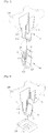
- Fig. 1 is an exploded perspective view of a plastic clip according to one embodiment of the present invention
- Fig. 2 is a perspective view showing a state before a combination panel is combined with the plastic clip according to one embodiment of the present invention
- Fig. 3 is a perspective view showing a state after the combination panel is combined with the plastic clip according to one embodiment of the present invention.
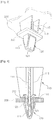
- Fig. 4 is a longitudinal cross-sectional view showing the state after the combination panel is combined with the plastic clip according to one embodiment of the present invention
- Fig. 5 is a substantial enlarged view of Fig. 4 .
- a plastic clip 100 of the present invention comprises a clip boss 110 integrally formed in a fixed panel 200; and a clip main body 120 detachably assembled to the clip boss 110.
- the clip boss 110 is provided with fitting portions 113 in two lower side portions of a vertical plate 111 wherein a fitting hole 112 is provided; locking projections 114 in front and back upper ends of the fitting portions 113; and support ribs 115 respectively on a front face and a back face of the vertical plate 111.
- the clip main body 120 is provided with an inverted triangular input portion 121 in a lower end portion; a locking projection 122 in an upper end portion of the input portion 121; a clip-boss input guide hole 123 in the center of an upper end; a clip-boss input guide portion 124 connected to the clip-boss input guide hole 123 in the center of an internal upper portion; and an elastic fitting piece 125 in a lower end of the clip-boss input guide portion 124.
- one side portion is configured as a fixed end integrally formed in a lower end portion on one side of the clip-boss input guide portion 124, and the other side portion is configured as a free end sealing a lower portion on the other side of the clip-boss input guide portion 124.
- the elastic fitting piece 125 of the clip main body 120 is provided with a locking projection 125a in a lower end on a free end side.
- the clip main body 120 is provided with clip-boss support projecting portions 126 on two internal sides of the input portion 121; and a connecting piece 127 between the lower end portion on one side of the clip-boss input guide portion 124 wherein the elastic fitting piece 125 is integrally formed, and the clip-boss support projecting portion 126 on one side.
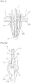
- Figs. 6a to 6d are drawings showing a combination process of the clip main body wherein the clip main body is combined with the clip boss in the plastic clip according to one embodiment of the present invention.
- the clip main body 120 when the clip main body 120 is combined with the clip boss 110 integrally formed in the fixed panel 200, as shown in Fig. 6a , first, after the vertical plate 111 of the clip boss 110 is inserted into the clip-boss input guide portion 124 through the clip-boss input guide hole 123 of the clip main body 120, if a lower end of the vertical plate 111 abuts against the elastic fitting piece 125, the vertical plate 111 is tilted for only a given angle (for example, 15 degrees) to the free end side of the elastic fitting piece 125, and is continuously inserted.
- a given angle for example, 15 degrees
- the locking projections 114 provided in the upper end of the fitting portions 113 of the clip boss 110 are locked in an upper end of the combination panel 300, and the locking projection 122 provided in the upper end of the input portion 121 of the clip main body 120 is locked in a lower end of the combination hole 310 so as to be capable of an assembly between the fixed panel 200 and the combination panel 300.
- the input portion 121 of the clip main body 120 can pass the combination hole 310 while interiorly being narrowed, so that the fixed panel 200 can be pulled out of the combination panel 300.
Landscapes
- Engineering & Computer Science (AREA)
- General Engineering & Computer Science (AREA)
- Mechanical Engineering (AREA)
- Insertion Pins And Rivets (AREA)
- Connection Of Plates (AREA)
- Buckles (AREA)
Description
- The present invention relates to a plastic clip with the features of the preamble of claim 1.
- Generally, various interior materials beginning with a fascia board (FACIA) inside an automobile are configured wherein a combination panel is assembled to the fixed panel, and when the combination panel is assembled to the fixed panel in this manner, there are many examples using a plastic clip composed of the clip boss integrally formed in the fixed panel, and the clip main body detachably assembled to the clip boss.
- However, conventionally, in the plastic clip composed of the clip boss integrally formed in the fixed panel, and the clip main body detachably assembled to the clip boss, it is very difficult to assemble the clip main body to the clip boss or disassemble, so that there are problems that not only many assembly hours are required, but also many assembly defects occur so as to cause a low productivity and a cost increase. Also, there is a problem that a breakdown repair relative to the combination panel is difficult.
- Also, in a conventional structure, an assembly state of the clip main body relative to the clip boss is unstable, and there is a problem that a flowage and noise of the clip main body due to an external impact in a usage process occur.
WO 2007/126201 A1 discloses a plastic clip in accordance with the preamble of claim 1.Disclosure of the Invention - The present invention is made in view of the aforementioned conventional actual conditions, and an object thereof is to provide a plastic clip capable of preventing the flowage and noise due to the external impact by firmly combining the clip main body with the clip boss integrally formed in the fixed panel.
- In order to obtain the aforementioned object, a plastic clip of the present invention comprises the features of claim 1.
- In the plastic clip of the present invention, the clip boss is configured wherein a fitting portion is provided in two lower side portions of a vertical plate provided with a fitting hole; and locking projections provided in front and back upper ends of the fitting portion. The clip main body has an inverted triangular input portion provided in a lower end portion; a locking projection provided in an upper end portion of the input portion; a clip-boss input guide hole provided in the center of an upper end; a clip-boss input guide portion connected to the clip-boss input guide hole provided in the center of an internal upper portion; and an elastic fitting piece provided in a lower end of the clip-boss input guide portion.
- Also, in the plastic clip of the present invention, the elastic fitting piece of the clip main body has one side portion as a fixed end integrally formed in a lower end portion on one side of the clip-boss input guide portion, and the other side portion as a free end sealing a lower portion on the other side of the clip-boss input guide portion.
- In the plastic clip of the present invention, the clip main body has a clip-boss support projecting portions provided on two internal sides of the input portion; and a connecting piece provided between the lower end portion on one side of the clip-boss input guide portion formed integrally with the elastic fitting piece, and the clip-boss support projecting portion on one side.
- In the plastic clip of the present invention, the clip main body is easily and firmly assembled to the clip boss integrally formed in the fixed panel, so that as well as improving an assembly property of the clip main body, a flowage or noise of the clip main body due to an external impact in a usage process can be significantly reduced, and in a process of assembling the fixed panel to the combination panel or disassembling the fixed panel from the combination panel, a breakage of the clip main body can be prevented so as to obtain an effect of significantly improving a durability and merchantability of the plastic clip.
-
-
Fig. 1 is an exploded perspective view of a plastic clip according to one embodiment of the present invention. -
Fig. 2 is a perspective view showing a state before a combination panel is combined with the plastic clip according to one embodiment of the present invention. -
Fig. 3 is a perspective view showing a state after the combination panel is combined with the plastic clip according to one embodiment of the present invention. -
Fig. 4 is a longitudinal cross-sectional view showing the state after the combination panel is combined with the plastic clip according to one embodiment of the present invention. -
Fig. 5 is a substantial enlarged view ofFig. 4 . -
Figs. 6a to 6d are drawings showing a combination process of a clip main body wherein the clip main body is combined with a clip boss in the plastic clip according to one embodiment of the present invention. - Hereinafter, specific description of the present invention for obtaining the aforementioned object will be explained in detail based on attached drawings.
-
Fig. 1 is an exploded perspective view of a plastic clip according to one embodiment of the present invention;Fig. 2 is a perspective view showing a state before a combination panel is combined with the plastic clip according to one embodiment of the present invention; andFig. 3 is a perspective view showing a state after the combination panel is combined with the plastic clip according to one embodiment of the present invention. - Also,
Fig. 4 is a longitudinal cross-sectional view showing the state after the combination panel is combined with the plastic clip according to one embodiment of the present invention; andFig. 5 is a substantial enlarged view ofFig. 4 . - As shown in
Fig. 1 to Fig. 5 , a plastic clip 100 of the present invention comprises aclip boss 110 integrally formed in a fixedpanel 200; and a clipmain body 120 detachably assembled to theclip boss 110. - In the clip 100 of the present invention, the
clip boss 110 is provided withfitting portions 113 in two lower side portions of avertical plate 111 wherein afitting hole 112 is provided;locking projections 114 in front and back upper ends of thefitting portions 113; and supportribs 115 respectively on a front face and a back face of thevertical plate 111. - Also, the clip
main body 120 is provided with an invertedtriangular input portion 121 in a lower end portion; alocking projection 122 in an upper end portion of theinput portion 121; a clip-bossinput guide hole 123 in the center of an upper end; a clip-bossinput guide portion 124 connected to the clip-bossinput guide hole 123 in the center of an internal upper portion; and anelastic fitting piece 125 in a lower end of the clip-bossinput guide portion 124. - In the
elastic fitting piece 125 of the clipmain body 120, one side portion is configured as a fixed end integrally formed in a lower end portion on one side of the clip-bossinput guide portion 124, and the other side portion is configured as a free end sealing a lower portion on the other side of the clip-bossinput guide portion 124. Theelastic fitting piece 125 of the clipmain body 120 is provided with alocking projection 125a in a lower end on a free end side. - On the other hand, in an illustrated embodiment, the clip
main body 120 is provided with clip-bosssupport projecting portions 126 on two internal sides of theinput portion 121; and a connectingpiece 127 between the lower end portion on one side of the clip-bossinput guide portion 124 wherein theelastic fitting piece 125 is integrally formed, and the clip-bosssupport projecting portion 126 on one side. -
Figs. 6a to 6d are drawings showing a combination process of the clip main body wherein the clip main body is combined with the clip boss in the plastic clip according to one embodiment of the present invention. - In the clip 100 of the present invention, when the clip
main body 120 is combined with theclip boss 110 integrally formed in thefixed panel 200, as shown inFig. 6a , first, after thevertical plate 111 of theclip boss 110 is inserted into the clip-bossinput guide portion 124 through the clip-bossinput guide hole 123 of the clipmain body 120, if a lower end of thevertical plate 111 abuts against theelastic fitting piece 125, thevertical plate 111 is tilted for only a given angle (for example, 15 degrees) to the free end side of theelastic fitting piece 125, and is continuously inserted. - As shown in
Fig. 6b , when the lower end of thevertical plate 111, which has passed outside theelastic fitting piece 125, abuts against the clip-bosssupport projecting portion 126 of the clipmain body 120, thevertical plate 111 is tilted in an opposite direction and is continuously inserted. As shown inFig. 6c , when an end portion of theelastic fitting piece 125 is inserted into thefitting hole 112 at the same time when the lower end of thevertical plate 111 abuts against an internal lower end of the clipmain body 120, thevertical plate 111 is vertically raised. - As shown in
Fig. 6d , when thevertical plate 111 is vertically raised, theelastic fitting piece 125 completely passes through thefitting hole 112, and the clip-bosssupport projecting portions 126 provided on the two internal sides of theinput portion 121 of the clipmain body 120 bilaterally push thevertical plate 111 so as to support thevertical plate 111. Accordingly, thelocking projection 125a provided in the lower end on the free end side of theelastic fitting piece 125 is locked in thefitting hole 112, so that even if thevertical plate 111 has flowed in a right-and-left direction, thevertical plate 111 becomes undetached from theelastic fitting piece 125. - Therefore, according to the plastic clip 100 of the present invention, a flowage or noise of the clip
main body 120 due to an external impact in a usage process disappears. - On the other hand, as mentioned above, after the clip
main body 120 has been combined with theclip boss 110 integrally formed in thefixed panel 200, when theinput portion 121 of the clipmain body 120 is inserted into acombination hole 310 formed in acombination panel 300, after theinput portion 121 of the clipmain body 120 has interiorly narrowed to pass thecombination hole 310, theinput portion 121 of the clipmain body 120 restores to its former state again. As a result, as shown inFig. 4 andFig. 5 , thelocking projections 114 provided in the upper end of thefitting portions 113 of theclip boss 110 are locked in an upper end of thecombination panel 300, and thelocking projection 122 provided in the upper end of theinput portion 121 of the clipmain body 120 is locked in a lower end of thecombination hole 310 so as to be capable of an assembly between thefixed panel 200 and thecombination panel 300. - Meanwhile, when the
fixed panel 200 is detached from thecombination panel 300, if a fastened portion of the plastic clip 100 relative to thefixed panel 200 is pulled to a side opposite to thecombination panel 300, theinput portion 121 of the clipmain body 120 can pass thecombination hole 310 while interiorly being narrowed, so that thefixed panel 200 can be pulled out of thecombination panel 300. - On the other hand, in a process of detaching the
fixed panel 200 from thecombination panel 300, if the fastened portion of the plastic clip 100 relative to thefixed panel 200 is pulled, first, thevertical plate 111 of theclip boss 110 integrally formed in thefixed panel 200 is pulled. As a result, theelastic fitting piece 125 of the clipmain body 120, which has been inserted in thefitting hole 112 of thevertical plate 111, is pulled, so that the clipmain body 120 is pulled. However, at that time, the free end of theelastic fitting piece 125 of the clipmain body 120 which is pulled together with thevertical plate 111 contacts the lower end of one side of the clip-bossinput guide portion 124. Accordingly, even if thefixed panel 200 is pulled by a slightly unreasonable force, as well as preventing a breakage of theelastic fitting piece 125, a tension force can be stably transmitted to the whole clipmain body 120. - The present invention explained above is not limited to the aforementioned embodiment and drawings, and it will be obvious to those having an ordinary skill in the art of the present invention that various replacements, deformations, and changes may be made without departing from the scope of the invention.
Claims (1)
- A plastic clip (100), comprising:a clip boss (110) integrally formed with a fixed panel (200); anda clip main body (120) detachably assembled to the clip boss (110),wherein the clip boss (110) includes:fitting portions (113) provided in two lower side portions of a vertical plate (111) having a fitting hole (112); andlocking projections (114) provided in front and back upper ends of the fitting portions (113); andwherein the clip main body (120) includes:an input portion (121) having an inverted triangular shape and provided in a lower end portion; andlocking projections (122) provided in upper end portions of the input portion (121);wherein, the plastic clip further comprises:a clip-boss input guide hole (123) provided in a center of an upper end;clip-boss input guide portions (124) provided in a center of an internal upper portion and connected to the clip-boss input guide hole (123); andan elastic fitting piece (125) provided in a lower end portion of a first one of the clip-boss input guide portions (124),wherein the elastic fitting piece (125) has one side portion as a fixed end integrally formed in the lower end portion of the first clip-boss input guide portion (124) on one side;wherein clip-boss support projecting portions (126) are provided on two internal sides of the input portion (121); and a connecting piece (127) is provided between the lower end portion of the first clip-boss input guide portion (124) and the clip-boss support projecting portion (126) on the one side, wherein the elastic fitting piece (125) is integrally formed with the connecting piece (127);characterized in that the elastic fitting piece (125) has as another side portion a free end sealing a lower portion of a second one of the clip-boss input guide portions (124) on the other side, and a locking projection (125a) in a lower end on a free end side.
Applications Claiming Priority (2)
| Application Number | Priority Date | Filing Date | Title |
|---|---|---|---|
| KR1020110014045A KR20120094653A (en) | 2011-02-17 | 2011-02-17 | A plastic clip |
| PCT/KR2012/001139 WO2012111977A2 (en) | 2011-02-17 | 2012-02-15 | Plastic clip |
Publications (3)
| Publication Number | Publication Date |
|---|---|
| EP2676848A2 EP2676848A2 (en) | 2013-12-25 |
| EP2676848A4 EP2676848A4 (en) | 2014-07-02 |
| EP2676848B1 true EP2676848B1 (en) | 2017-08-30 |
Family
ID=46673046
Family Applications (1)
| Application Number | Title | Priority Date | Filing Date |
|---|---|---|---|
| EP12747552.3A Active EP2676848B1 (en) | 2011-02-17 | 2012-02-15 | Plastic clip |
Country Status (7)
| Country | Link |
|---|---|
| US (1) | US9003616B2 (en) |
| EP (1) | EP2676848B1 (en) |
| JP (1) | JP5941071B2 (en) |
| KR (1) | KR20120094653A (en) |
| CN (1) | CN103370229B (en) |
| TW (1) | TWI510390B (en) |
| WO (1) | WO2012111977A2 (en) |
Families Citing this family (30)
| Publication number | Priority date | Publication date | Assignee | Title |
|---|---|---|---|---|
| US10336265B2 (en) * | 2015-10-21 | 2019-07-02 | Termax Llc | Fastener clip over a carrier secured with hooks |
| JP5666400B2 (en) * | 2011-08-24 | 2015-02-12 | 大和化成工業株式会社 | clip |
| JP5839749B2 (en) * | 2012-04-02 | 2016-01-06 | 株式会社パイオラックス | Clip device |
| JP6274852B2 (en) * | 2013-12-17 | 2018-02-07 | カルソニックカンセイ株式会社 | Mounting structure for in-vehicle equipment |
| SG10201913698XA (en) * | 2014-06-18 | 2020-03-30 | Fisher & Paykel Healthcare Ltd | Patient interface and component parts |
| JP1518019S (en) * | 2014-08-05 | 2015-02-23 | ||
| DE102015209881A1 (en) * | 2015-05-29 | 2016-12-01 | A.RAYMOND et Cie. SCS | Device for holding a component |
| JP6754031B2 (en) * | 2015-12-25 | 2020-09-09 | 北川工業株式会社 | Clip and fixing mechanism |
| JP6722501B2 (en) * | 2016-04-25 | 2020-07-15 | 株式会社タチエス | Resin cover and vehicle seat equipped with resin cover |
| CN105889256A (en) * | 2016-06-30 | 2016-08-24 | 赣州禾盈通用零部件有限公司 | Multi-connecting rivet |
| CN107487382A (en) * | 2016-12-24 | 2017-12-19 | 宝沃汽车(中国)有限公司 | Buckle, interface arrangment, wheel arch attachment structure and vehicle |
| JP6409044B2 (en) * | 2016-12-28 | 2018-10-17 | 株式会社ニフコ | Member mounting structure and mounting clip |
| JP6946109B2 (en) * | 2017-08-09 | 2021-10-06 | 大和化成工業株式会社 | clip |
| KR101987876B1 (en) | 2017-11-08 | 2019-06-12 | 주식회사 서연이화 | Mounting clip assembly for trim |
| US11519222B1 (en) * | 2017-11-08 | 2022-12-06 | Christopher Lee Hubschmitt | Screen retention device and method of use |
| US10442329B2 (en) * | 2017-11-09 | 2019-10-15 | B/E Aerospace Fischer Gmbh | Clip and method for attaching and tensioning seat dress covers |
| JP6917298B2 (en) * | 2017-12-27 | 2021-08-11 | 大和化成工業株式会社 | clip |
| FR3084118B1 (en) * | 2018-07-19 | 2020-11-27 | A Raymond Et Cie | FIXING DEVICE FOR TWO FLAT ELEMENTS |
| KR102104890B1 (en) * | 2019-01-28 | 2020-04-27 | 주식회사 성우하이텍 | Clip for adhering different kinds materials and adhering structure of different kinds materials using thereof |
| US11149774B2 (en) | 2019-10-03 | 2021-10-19 | Newfrey Llc | Bathtub fastener assembly |
| US10968931B1 (en) | 2019-10-17 | 2021-04-06 | Newfrey Llc | Dual component sealing fastener and coupling assembly including same |
| KR102310013B1 (en) | 2020-03-04 | 2021-10-08 | 주식회사 니프코코리아 | Trim fastening clip |
| US12264694B2 (en) | 2020-04-28 | 2025-04-01 | Piolax, Inc. | Fastener |
| US11746812B2 (en) | 2021-05-12 | 2023-09-05 | Newfrey Llc | Dual component sealing fastener and coupling assembly including same |
| CN114607690B (en) * | 2022-03-01 | 2023-06-23 | 嘉兴汉工汽车紧固件有限公司 | Fastening device and fastening assembly for fixing parts |
| CN118793680A (en) * | 2023-04-13 | 2024-10-18 | 伊利诺斯工具制品有限公司 | fastener |
| IT202300012939A1 (en) * | 2023-06-22 | 2024-12-22 | Enel Green Power Italia S R L | FASTENING DEVICE FOR PHOTOVOLTAIC MODULES, IN PARTICULAR PLASTIC PHOTOVOLTAIC MODULES |
| CN117465360A (en) * | 2023-12-04 | 2024-01-30 | 安徽江淮汽车集团股份有限公司 | A plastic buckle structure |
| WO2025243924A1 (en) * | 2024-05-23 | 2025-11-27 | 株式会社パイオラックス | Clip |
| TWM662453U (en) * | 2024-07-29 | 2024-11-01 | 閎博科技有限公司 | Ceiling fan blade quick assembly structure |
Citations (1)
| Publication number | Priority date | Publication date | Assignee | Title |
|---|---|---|---|---|
| WO2007126201A1 (en) * | 2006-04-28 | 2007-11-08 | Trw Controls & Fasteners Inc. | Automotive fastener |
Family Cites Families (23)
| Publication number | Priority date | Publication date | Assignee | Title |
|---|---|---|---|---|
| JPS6051513U (en) * | 1983-09-16 | 1985-04-11 | 古河電気工業株式会社 | Optical transmission body clamping device |
| JPH0735130Y2 (en) * | 1989-11-06 | 1995-08-09 | マツダ株式会社 | Metal clip |
| JPH0651513U (en) * | 1992-12-25 | 1994-07-15 | 日本プラスト株式会社 | Sticking device |
| JPH1054411A (en) * | 1996-06-03 | 1998-02-24 | Daiwa Kasei Kogyo Kk | Clip |
| JP2932385B1 (en) * | 1998-02-12 | 1999-08-09 | 株式会社パイオラックス | Component mounting structure |
| JP4657419B2 (en) * | 2000-05-22 | 2011-03-23 | 株式会社ニフコ | clip |
| US8627552B2 (en) * | 2001-06-25 | 2014-01-14 | Termax Corporation | Multicontact adaptive fastener clip |
| US6449814B1 (en) * | 2001-09-13 | 2002-09-17 | Summit Polymers, Inc. | Trim fastener clip employing multiple lines-of-contact stabilization |
| JP4227741B2 (en) * | 2001-10-29 | 2009-02-18 | 株式会社ニフコ | clip |
| US6796006B2 (en) * | 2002-04-25 | 2004-09-28 | Illinois Tool Works Inc. | Rib clip |
| US7300089B2 (en) * | 2003-10-06 | 2007-11-27 | Piolax Inc. | Fixing member and a fixing structure for vehicle part |
| JP4190409B2 (en) * | 2003-12-26 | 2008-12-03 | 株式会社パイオラックス | clip |
| US7461436B2 (en) * | 2004-10-26 | 2008-12-09 | Piolax, Inc. | Mounting structure of vehicle interior material |
| KR200389499Y1 (en) * | 2005-04-29 | 2005-07-18 | 주식회사 키프코 | Automobile clip |
| KR100970986B1 (en) * | 2005-06-08 | 2010-07-20 | 한국 티알더블류 자동차부품산업 주식회사 | Plastic fasteners |
| US7401388B2 (en) * | 2005-09-06 | 2008-07-22 | Illinois Tool Works Inc. | Rib clip |
| JP4884022B2 (en) * | 2006-02-10 | 2012-02-22 | 株式会社パイオラックス | Parts mounting device |
| JP4713455B2 (en) * | 2006-12-19 | 2011-06-29 | 株式会社パイオラックス | clip |
| AU314030S (en) * | 2007-02-16 | 2007-05-08 | Itw Australia Pty Ltd | Clip |
| US7805815B2 (en) * | 2007-08-22 | 2010-10-05 | Toyota Motor Engineering & Manufacturing North America, Inc. | Clip |
| JP4540726B2 (en) * | 2008-07-04 | 2010-09-08 | 大和化成工業株式会社 | Two-part assembly structure |
| KR20100009891U (en) * | 2009-03-31 | 2010-10-08 | 주식회사 니프코코리아 | a panel mounting structure using clip |
| KR101094558B1 (en) * | 2009-08-12 | 2011-12-19 | 주식회사 니프코코리아 | Automotive plastic clips |
-
2011
- 2011-02-17 KR KR1020110014045A patent/KR20120094653A/en not_active Ceased
-
2012
- 2012-02-10 TW TW101104313A patent/TWI510390B/en not_active IP Right Cessation
- 2012-02-15 EP EP12747552.3A patent/EP2676848B1/en active Active
- 2012-02-15 WO PCT/KR2012/001139 patent/WO2012111977A2/en not_active Ceased
- 2012-02-15 US US13/985,327 patent/US9003616B2/en active Active
- 2012-02-15 JP JP2013554390A patent/JP5941071B2/en active Active
- 2012-02-15 CN CN201280009095.2A patent/CN103370229B/en active Active
Patent Citations (1)
| Publication number | Priority date | Publication date | Assignee | Title |
|---|---|---|---|---|
| WO2007126201A1 (en) * | 2006-04-28 | 2007-11-08 | Trw Controls & Fasteners Inc. | Automotive fastener |
Also Published As
| Publication number | Publication date |
|---|---|
| JP2014506982A (en) | 2014-03-20 |
| TW201249686A (en) | 2012-12-16 |
| TWI510390B (en) | 2015-12-01 |
| WO2012111977A2 (en) | 2012-08-23 |
| US9003616B2 (en) | 2015-04-14 |
| EP2676848A2 (en) | 2013-12-25 |
| CN103370229B (en) | 2016-01-20 |
| CN103370229A (en) | 2013-10-23 |
| JP5941071B2 (en) | 2016-06-29 |
| EP2676848A4 (en) | 2014-07-02 |
| US20140000071A1 (en) | 2014-01-02 |
| KR20120094653A (en) | 2012-08-27 |
| WO2012111977A3 (en) | 2012-10-11 |
Similar Documents
| Publication | Publication Date | Title |
|---|---|---|
| US9003616B2 (en) | Plastic clip | |
| JP4379492B2 (en) | Cabinet assembly structure and thin display device | |
| US9340107B2 (en) | Support structure for fuel lid | |
| WO2015098538A1 (en) | Bonded structure of dissimilar materials | |
| US7913872B2 (en) | Baffle unit | |
| WO2012120983A1 (en) | Guide device for fuel filling nozzle | |
| US8191843B2 (en) | Mudguard mounting structure | |
| WO2020215943A1 (en) | Middle frame assembly and air conditioner | |
| CN101923230B (en) | Elastic clamping piece and liquid crystal module with same | |
| KR101693846B1 (en) | Bumper back-beam for vehicle | |
| KR101094558B1 (en) | Automotive plastic clips | |
| US9169966B2 (en) | Compression limiting clip for a bracket assembly | |
| CN101863251B (en) | Mounting bracket for fuse box of automotive electrical appliance | |
| JP5505059B2 (en) | Display device | |
| JP5307936B2 (en) | Mounting member mounting structure | |
| JP5677057B2 (en) | Filter frame | |
| CN203172588U (en) | Fixing mechanism of safety belt locking tongue | |
| JP2009001198A (en) | Bumper mounting structure | |
| CN203968247U (en) | Buckle and adopt the television rear shell of described buckle | |
| JP2008012953A (en) | Interior part for automobile | |
| JP5649442B2 (en) | Parts mounting structure | |
| CN203023669U (en) | Plate passing joint assembly for vehicle and vehicle provided with plate passing joint assembly | |
| CN101850708B (en) | Door structure for vehicle | |
| KR101188846B1 (en) | opening bracket combine structure | |
| CN113002465A (en) | Connection structure of exterior member |
Legal Events
| Date | Code | Title | Description |
|---|---|---|---|
| PUAI | Public reference made under article 153(3) epc to a published international application that has entered the european phase |
Free format text: ORIGINAL CODE: 0009012 |
|
| 17P | Request for examination filed |
Effective date: 20130816 |
|
| AK | Designated contracting states |
Kind code of ref document: A2 Designated state(s): AL AT BE BG CH CY CZ DE DK EE ES FI FR GB GR HR HU IE IS IT LI LT LU LV MC MK MT NL NO PL PT RO RS SE SI SK SM TR |
|
| DAX | Request for extension of the european patent (deleted) | ||
| A4 | Supplementary search report drawn up and despatched |
Effective date: 20140530 |
|
| RIC1 | Information provided on ipc code assigned before grant |
Ipc: B60R 16/02 20060101AFI20140523BHEP Ipc: B60R 16/00 20060101ALI20140523BHEP Ipc: B60R 13/02 20060101ALI20140523BHEP |
|
| 17Q | First examination report despatched |
Effective date: 20150409 |
|
| GRAP | Despatch of communication of intention to grant a patent |
Free format text: ORIGINAL CODE: EPIDOSNIGR1 |
|
| INTG | Intention to grant announced |
Effective date: 20170503 |
|
| GRAS | Grant fee paid |
Free format text: ORIGINAL CODE: EPIDOSNIGR3 |
|
| GRAA | (expected) grant |
Free format text: ORIGINAL CODE: 0009210 |
|
| RAP1 | Party data changed (applicant data changed or rights of an application transferred) |
Owner name: NIFCO KOREA INC. |
|
| RIN1 | Information on inventor provided before grant (corrected) |
Inventor name: CHOI, YOUN YOUNG |
|
| AK | Designated contracting states |
Kind code of ref document: B1 Designated state(s): AL AT BE BG CH CY CZ DE DK EE ES FI FR GB GR HR HU IE IS IT LI LT LU LV MC MK MT NL NO PL PT RO RS SE SI SK SM TR |
|
| REG | Reference to a national code |
Ref country code: GB Ref legal event code: FG4D |
|
| REG | Reference to a national code |
Ref country code: CH Ref legal event code: EP |
|
| REG | Reference to a national code |
Ref country code: AT Ref legal event code: REF Ref document number: 923192 Country of ref document: AT Kind code of ref document: T Effective date: 20170915 |
|
| REG | Reference to a national code |
Ref country code: IE Ref legal event code: FG4D |
|
| REG | Reference to a national code |
Ref country code: DE Ref legal event code: R096 Ref document number: 602012036635 Country of ref document: DE |
|
| REG | Reference to a national code |
Ref country code: NL Ref legal event code: MP Effective date: 20170830 |
|
| REG | Reference to a national code |
Ref country code: LT Ref legal event code: MG4D |
|
| REG | Reference to a national code |
Ref country code: AT Ref legal event code: MK05 Ref document number: 923192 Country of ref document: AT Kind code of ref document: T Effective date: 20170830 |
|
| PG25 | Lapsed in a contracting state [announced via postgrant information from national office to epo] |
Ref country code: NO Free format text: LAPSE BECAUSE OF FAILURE TO SUBMIT A TRANSLATION OF THE DESCRIPTION OR TO PAY THE FEE WITHIN THE PRESCRIBED TIME-LIMIT Effective date: 20171130 Ref country code: LT Free format text: LAPSE BECAUSE OF FAILURE TO SUBMIT A TRANSLATION OF THE DESCRIPTION OR TO PAY THE FEE WITHIN THE PRESCRIBED TIME-LIMIT Effective date: 20170830 Ref country code: SE Free format text: LAPSE BECAUSE OF FAILURE TO SUBMIT A TRANSLATION OF THE DESCRIPTION OR TO PAY THE FEE WITHIN THE PRESCRIBED TIME-LIMIT Effective date: 20170830 Ref country code: AT Free format text: LAPSE BECAUSE OF FAILURE TO SUBMIT A TRANSLATION OF THE DESCRIPTION OR TO PAY THE FEE WITHIN THE PRESCRIBED TIME-LIMIT Effective date: 20170830 Ref country code: FI Free format text: LAPSE BECAUSE OF FAILURE TO SUBMIT A TRANSLATION OF THE DESCRIPTION OR TO PAY THE FEE WITHIN THE PRESCRIBED TIME-LIMIT Effective date: 20170830 Ref country code: HR Free format text: LAPSE BECAUSE OF FAILURE TO SUBMIT A TRANSLATION OF THE DESCRIPTION OR TO PAY THE FEE WITHIN THE PRESCRIBED TIME-LIMIT Effective date: 20170830 |
|
| PG25 | Lapsed in a contracting state [announced via postgrant information from national office to epo] |
Ref country code: BG Free format text: LAPSE BECAUSE OF FAILURE TO SUBMIT A TRANSLATION OF THE DESCRIPTION OR TO PAY THE FEE WITHIN THE PRESCRIBED TIME-LIMIT Effective date: 20171130 Ref country code: IS Free format text: LAPSE BECAUSE OF FAILURE TO SUBMIT A TRANSLATION OF THE DESCRIPTION OR TO PAY THE FEE WITHIN THE PRESCRIBED TIME-LIMIT Effective date: 20171230 Ref country code: LV Free format text: LAPSE BECAUSE OF FAILURE TO SUBMIT A TRANSLATION OF THE DESCRIPTION OR TO PAY THE FEE WITHIN THE PRESCRIBED TIME-LIMIT Effective date: 20170830 Ref country code: ES Free format text: LAPSE BECAUSE OF FAILURE TO SUBMIT A TRANSLATION OF THE DESCRIPTION OR TO PAY THE FEE WITHIN THE PRESCRIBED TIME-LIMIT Effective date: 20170830 Ref country code: RS Free format text: LAPSE BECAUSE OF FAILURE TO SUBMIT A TRANSLATION OF THE DESCRIPTION OR TO PAY THE FEE WITHIN THE PRESCRIBED TIME-LIMIT Effective date: 20170830 |
|
| PG25 | Lapsed in a contracting state [announced via postgrant information from national office to epo] |
Ref country code: NL Free format text: LAPSE BECAUSE OF FAILURE TO SUBMIT A TRANSLATION OF THE DESCRIPTION OR TO PAY THE FEE WITHIN THE PRESCRIBED TIME-LIMIT Effective date: 20170830 |
|
| PG25 | Lapsed in a contracting state [announced via postgrant information from national office to epo] |
Ref country code: CZ Free format text: LAPSE BECAUSE OF FAILURE TO SUBMIT A TRANSLATION OF THE DESCRIPTION OR TO PAY THE FEE WITHIN THE PRESCRIBED TIME-LIMIT Effective date: 20170830 Ref country code: DK Free format text: LAPSE BECAUSE OF FAILURE TO SUBMIT A TRANSLATION OF THE DESCRIPTION OR TO PAY THE FEE WITHIN THE PRESCRIBED TIME-LIMIT Effective date: 20170830 Ref country code: PL Free format text: LAPSE BECAUSE OF FAILURE TO SUBMIT A TRANSLATION OF THE DESCRIPTION OR TO PAY THE FEE WITHIN THE PRESCRIBED TIME-LIMIT Effective date: 20170830 Ref country code: RO Free format text: LAPSE BECAUSE OF FAILURE TO SUBMIT A TRANSLATION OF THE DESCRIPTION OR TO PAY THE FEE WITHIN THE PRESCRIBED TIME-LIMIT Effective date: 20170830 |
|
| PG25 | Lapsed in a contracting state [announced via postgrant information from national office to epo] |
Ref country code: SM Free format text: LAPSE BECAUSE OF FAILURE TO SUBMIT A TRANSLATION OF THE DESCRIPTION OR TO PAY THE FEE WITHIN THE PRESCRIBED TIME-LIMIT Effective date: 20170830 Ref country code: SK Free format text: LAPSE BECAUSE OF FAILURE TO SUBMIT A TRANSLATION OF THE DESCRIPTION OR TO PAY THE FEE WITHIN THE PRESCRIBED TIME-LIMIT Effective date: 20170830 Ref country code: EE Free format text: LAPSE BECAUSE OF FAILURE TO SUBMIT A TRANSLATION OF THE DESCRIPTION OR TO PAY THE FEE WITHIN THE PRESCRIBED TIME-LIMIT Effective date: 20170830 Ref country code: IT Free format text: LAPSE BECAUSE OF FAILURE TO SUBMIT A TRANSLATION OF THE DESCRIPTION OR TO PAY THE FEE WITHIN THE PRESCRIBED TIME-LIMIT Effective date: 20170830 |
|
| REG | Reference to a national code |
Ref country code: DE Ref legal event code: R097 Ref document number: 602012036635 Country of ref document: DE |
|
| PLBE | No opposition filed within time limit |
Free format text: ORIGINAL CODE: 0009261 |
|
| STAA | Information on the status of an ep patent application or granted ep patent |
Free format text: STATUS: NO OPPOSITION FILED WITHIN TIME LIMIT |
|
| 26N | No opposition filed |
Effective date: 20180531 |
|
| PG25 | Lapsed in a contracting state [announced via postgrant information from national office to epo] |
Ref country code: SI Free format text: LAPSE BECAUSE OF FAILURE TO SUBMIT A TRANSLATION OF THE DESCRIPTION OR TO PAY THE FEE WITHIN THE PRESCRIBED TIME-LIMIT Effective date: 20170830 |
|
| REG | Reference to a national code |
Ref country code: CH Ref legal event code: PL |
|
| PG25 | Lapsed in a contracting state [announced via postgrant information from national office to epo] |
Ref country code: MC Free format text: LAPSE BECAUSE OF FAILURE TO SUBMIT A TRANSLATION OF THE DESCRIPTION OR TO PAY THE FEE WITHIN THE PRESCRIBED TIME-LIMIT Effective date: 20170830 |
|
| REG | Reference to a national code |
Ref country code: IE Ref legal event code: MM4A |
|
| REG | Reference to a national code |
Ref country code: BE Ref legal event code: MM Effective date: 20180228 |
|
| PG25 | Lapsed in a contracting state [announced via postgrant information from national office to epo] |
Ref country code: LI Free format text: LAPSE BECAUSE OF NON-PAYMENT OF DUE FEES Effective date: 20180228 Ref country code: LU Free format text: LAPSE BECAUSE OF NON-PAYMENT OF DUE FEES Effective date: 20180215 Ref country code: CH Free format text: LAPSE BECAUSE OF NON-PAYMENT OF DUE FEES Effective date: 20180228 |
|
| REG | Reference to a national code |
Ref country code: FR Ref legal event code: ST Effective date: 20181031 |
|
| PG25 | Lapsed in a contracting state [announced via postgrant information from national office to epo] |
Ref country code: IE Free format text: LAPSE BECAUSE OF NON-PAYMENT OF DUE FEES Effective date: 20180215 |
|
| PG25 | Lapsed in a contracting state [announced via postgrant information from national office to epo] |
Ref country code: BE Free format text: LAPSE BECAUSE OF NON-PAYMENT OF DUE FEES Effective date: 20180228 Ref country code: FR Free format text: LAPSE BECAUSE OF NON-PAYMENT OF DUE FEES Effective date: 20180228 |
|
| PG25 | Lapsed in a contracting state [announced via postgrant information from national office to epo] |
Ref country code: MT Free format text: LAPSE BECAUSE OF NON-PAYMENT OF DUE FEES Effective date: 20180215 |
|
| PG25 | Lapsed in a contracting state [announced via postgrant information from national office to epo] |
Ref country code: TR Free format text: LAPSE BECAUSE OF FAILURE TO SUBMIT A TRANSLATION OF THE DESCRIPTION OR TO PAY THE FEE WITHIN THE PRESCRIBED TIME-LIMIT Effective date: 20170830 |
|
| PG25 | Lapsed in a contracting state [announced via postgrant information from national office to epo] |
Ref country code: HU Free format text: LAPSE BECAUSE OF FAILURE TO SUBMIT A TRANSLATION OF THE DESCRIPTION OR TO PAY THE FEE WITHIN THE PRESCRIBED TIME-LIMIT; INVALID AB INITIO Effective date: 20120215 Ref country code: PT Free format text: LAPSE BECAUSE OF FAILURE TO SUBMIT A TRANSLATION OF THE DESCRIPTION OR TO PAY THE FEE WITHIN THE PRESCRIBED TIME-LIMIT Effective date: 20170830 |
|
| PG25 | Lapsed in a contracting state [announced via postgrant information from national office to epo] |
Ref country code: MK Free format text: LAPSE BECAUSE OF NON-PAYMENT OF DUE FEES Effective date: 20170830 Ref country code: GR Free format text: LAPSE BECAUSE OF FAILURE TO SUBMIT A TRANSLATION OF THE DESCRIPTION OR TO PAY THE FEE WITHIN THE PRESCRIBED TIME-LIMIT Effective date: 20170830 Ref country code: CY Free format text: LAPSE BECAUSE OF FAILURE TO SUBMIT A TRANSLATION OF THE DESCRIPTION OR TO PAY THE FEE WITHIN THE PRESCRIBED TIME-LIMIT Effective date: 20170830 |
|
| PG25 | Lapsed in a contracting state [announced via postgrant information from national office to epo] |
Ref country code: AL Free format text: LAPSE BECAUSE OF FAILURE TO SUBMIT A TRANSLATION OF THE DESCRIPTION OR TO PAY THE FEE WITHIN THE PRESCRIBED TIME-LIMIT Effective date: 20170830 |
|
| PGFP | Annual fee paid to national office [announced via postgrant information from national office to epo] |
Ref country code: GB Payment date: 20260106 Year of fee payment: 15 |
|
| PGFP | Annual fee paid to national office [announced via postgrant information from national office to epo] |
Ref country code: DE Payment date: 20251230 Year of fee payment: 15 |