EP2676815A1 - Pneumatic tyre for a vehicle - Google Patents
Pneumatic tyre for a vehicle Download PDFInfo
- Publication number
- EP2676815A1 EP2676815A1 EP13169827.6A EP13169827A EP2676815A1 EP 2676815 A1 EP2676815 A1 EP 2676815A1 EP 13169827 A EP13169827 A EP 13169827A EP 2676815 A1 EP2676815 A1 EP 2676815A1
- Authority
- EP
- European Patent Office
- Prior art keywords
- extension
- groove
- row
- elevations
- tread pattern
- Prior art date
- Legal status (The legal status is an assumption and is not a legal conclusion. Google has not performed a legal analysis and makes no representation as to the accuracy of the status listed.)
- Granted
Links
- 230000003247 decreasing effect Effects 0.000 claims description 2
- 230000002093 peripheral effect Effects 0.000 abstract description 5
- 230000015572 biosynthetic process Effects 0.000 description 19
- 238000005755 formation reaction Methods 0.000 description 19
- XLYOFNOQVPJJNP-UHFFFAOYSA-N water Substances O XLYOFNOQVPJJNP-UHFFFAOYSA-N 0.000 description 7
- 230000001914 calming effect Effects 0.000 description 4
- 230000000694 effects Effects 0.000 description 4
- 238000005457 optimization Methods 0.000 description 4
- 241000251730 Chondrichthyes Species 0.000 description 3
- 238000004519 manufacturing process Methods 0.000 description 2
- QNRATNLHPGXHMA-XZHTYLCXSA-N (r)-(6-ethoxyquinolin-4-yl)-[(2s,4s,5r)-5-ethyl-1-azabicyclo[2.2.2]octan-2-yl]methanol;hydrochloride Chemical compound Cl.C([C@H]([C@H](C1)CC)C2)CN1[C@@H]2[C@H](O)C1=CC=NC2=CC=C(OCC)C=C21 QNRATNLHPGXHMA-XZHTYLCXSA-N 0.000 description 1
- 238000010521 absorption reaction Methods 0.000 description 1
- 230000005465 channeling Effects 0.000 description 1
- 230000007423 decrease Effects 0.000 description 1
- 238000007599 discharging Methods 0.000 description 1
- 230000002349 favourable effect Effects 0.000 description 1
- 239000000463 material Substances 0.000 description 1
- 238000012986 modification Methods 0.000 description 1
- 230000004048 modification Effects 0.000 description 1
- 230000002028 premature Effects 0.000 description 1
- 230000002441 reversible effect Effects 0.000 description 1
- 230000003068 static effect Effects 0.000 description 1
Images


Classifications
-
- B—PERFORMING OPERATIONS; TRANSPORTING
- B60—VEHICLES IN GENERAL
- B60C—VEHICLE TYRES; TYRE INFLATION; TYRE CHANGING; CONNECTING VALVES TO INFLATABLE ELASTIC BODIES IN GENERAL; DEVICES OR ARRANGEMENTS RELATED TO TYRES
- B60C11/00—Tyre tread bands; Tread patterns; Anti-skid inserts
- B60C11/03—Tread patterns
- B60C11/13—Tread patterns characterised by the groove cross-section, e.g. for buttressing or preventing stone-trapping
- B60C11/1307—Tread patterns characterised by the groove cross-section, e.g. for buttressing or preventing stone-trapping with special features of the groove walls
-
- B—PERFORMING OPERATIONS; TRANSPORTING
- B60—VEHICLES IN GENERAL
- B60C—VEHICLE TYRES; TYRE INFLATION; TYRE CHANGING; CONNECTING VALVES TO INFLATABLE ELASTIC BODIES IN GENERAL; DEVICES OR ARRANGEMENTS RELATED TO TYRES
- B60C11/00—Tyre tread bands; Tread patterns; Anti-skid inserts
- B60C11/03—Tread patterns
- B60C11/0306—Patterns comprising block rows or discontinuous ribs
- B60C11/0309—Patterns comprising block rows or discontinuous ribs further characterised by the groove cross-section
-
- B—PERFORMING OPERATIONS; TRANSPORTING
- B60—VEHICLES IN GENERAL
- B60C—VEHICLE TYRES; TYRE INFLATION; TYRE CHANGING; CONNECTING VALVES TO INFLATABLE ELASTIC BODIES IN GENERAL; DEVICES OR ARRANGEMENTS RELATED TO TYRES
- B60C11/00—Tyre tread bands; Tread patterns; Anti-skid inserts
- B60C11/03—Tread patterns
- B60C11/13—Tread patterns characterised by the groove cross-section, e.g. for buttressing or preventing stone-trapping
- B60C11/1307—Tread patterns characterised by the groove cross-section, e.g. for buttressing or preventing stone-trapping with special features of the groove walls
- B60C2011/133—Tread patterns characterised by the groove cross-section, e.g. for buttressing or preventing stone-trapping with special features of the groove walls comprising recesses
-
- B—PERFORMING OPERATIONS; TRANSPORTING
- B60—VEHICLES IN GENERAL
- B60C—VEHICLE TYRES; TYRE INFLATION; TYRE CHANGING; CONNECTING VALVES TO INFLATABLE ELASTIC BODIES IN GENERAL; DEVICES OR ARRANGEMENTS RELATED TO TYRES
- B60C11/00—Tyre tread bands; Tread patterns; Anti-skid inserts
- B60C11/03—Tread patterns
- B60C11/13—Tread patterns characterised by the groove cross-section, e.g. for buttressing or preventing stone-trapping
- B60C11/1307—Tread patterns characterised by the groove cross-section, e.g. for buttressing or preventing stone-trapping with special features of the groove walls
- B60C2011/1338—Tread patterns characterised by the groove cross-section, e.g. for buttressing or preventing stone-trapping with special features of the groove walls comprising protrusions
-
- B—PERFORMING OPERATIONS; TRANSPORTING
- B60—VEHICLES IN GENERAL
- B60C—VEHICLE TYRES; TYRE INFLATION; TYRE CHANGING; CONNECTING VALVES TO INFLATABLE ELASTIC BODIES IN GENERAL; DEVICES OR ARRANGEMENTS RELATED TO TYRES
- B60C11/00—Tyre tread bands; Tread patterns; Anti-skid inserts
- B60C11/03—Tread patterns
- B60C11/13—Tread patterns characterised by the groove cross-section, e.g. for buttressing or preventing stone-trapping
- B60C11/1353—Tread patterns characterised by the groove cross-section, e.g. for buttressing or preventing stone-trapping with special features of the groove bottom
- B60C2011/1361—Tread patterns characterised by the groove cross-section, e.g. for buttressing or preventing stone-trapping with special features of the groove bottom with protrusions extending from the groove bottom
Definitions
- the invention relates to a tread pattern of a vehicle tire - in particular a pneumatic vehicle tire - with grooves which radially separate profile elements from each other, wherein the grooves in the radial direction R in each case by a groove bottom and on both sides of the groove bottom in the direction of the adjacent profile element in each case by a profile element flank forming groove wall is limited, which extends in the radial direction R of the tire out of the groove bottom to the outside, with at least one groove having a main extension direction, the largest directional component in the circumferential direction U of the vehicle tire is formed.
- the circumferentially directed grooves serve mainly for receiving and discharging water when driving on wetted surfaces.
- the grooves are made as smooth as possible on their surfaces, so as to cause as little turbulence of the water as possible in this way.
- the invention has for its object to form a tread pattern with such grooves, which allow an improved, trouble-free flow behavior of the water in both directions of rotation of the tire.
- the object is achieved by the formation of a tread pattern of a vehicle tire - in particular a pneumatic vehicle tire - with grooves which radially separate profile elements from each other, wherein the grooves in the radial direction R in each case by a groove bottom and both sides of the groove bottom in the direction of the adjacent profile element respectively is defined by a profiled element flank forming groove wall which extends in the radial direction R of the tire out of the groove bottom to the outside, with at least one groove having a main extension direction, the largest direction component is formed in the circumferential direction U of the vehicle tire, according to the features of claim 1 solved, in which in the surface of at least one groove wall and / or the groove bottom a plurality of juxtaposed and aligned in the direction of extension of the groove first rows of in the direction of extension of the groove one behind the other and vo n are spaced apart arranged in the groove projecting elongated elevations formed in the extension direction of the groove measured extension length L 1 is greater than its extension width B 1 , wherein the
- the training allows by the juxtaposed, formed in the extension direction of the groove first rows of elongated elevations, the assurance of conductive mini-channels in the surface and thereby a guided flow along the surface of the groove, which has a calming effect on the flow.
- the offset in the direction of extension of the groove and overlapped arrangement of the elevations of the adjacent first rows allows a secure guiding function of the flow in the boundary layer and the spacing in the direction of extension of the groove to each other arranged formation of individual elevations within the first rows an additional calming of the flow.
- the effect is possible in both flow directions of the groove and thus in both directions of rotation of the tire.
- this design provides a kind of scale structure with island-like scales with a flow-guiding function over the entire extension of the rows. Miniturbulence due to premature stall can be reduced and laminar flow maintained longer.
- This training with the first rows of surveys spaced apart in the extension direction allows the implementation of streamlined training with relatively little engaging in the groove additional rubber volume, which among other things, the influence on the absorption capacity for receiving water can be minimized.
- a tread strip according to the features of claim 2, in which both sides of a first row between the first row and the adjacent first row each aligned in the extension direction of the groove second row of in the extension direction of the groove one behind the other and spaced from each other in the groove protruding elongated elevations is formed, measured in the extension direction of the groove extension length L 2 is greater than its extension width B 2 with L 2 ⁇ L 1 and B 2 ⁇ B 1 , wherein along the extension direction of the groove within the extension range of each survey the first row respectively an elevation of the adjacent to her second row with its full extension length L 2 is formed.
- a tread pattern according to the features of claim 3, wherein those to two adjacent first rows respectively associated second rows, which are arranged between the two first rows, are formed on a common extension line, wherein on the extension line, the elevations of to the first row to be assigned to a second row and the elevations of the second row to be assigned to the other first row are arranged in an alternating sequence.
- a tread strip according to the features of claim 4, in which between the first row and its associated second row each arranged in the extension direction of the groove third row of spaced in the direction of extension of the groove and spaced from each other, in the groove projecting elongated elevations is formed whose measured in the extension direction of the groove extension length L 3 is greater than its extension width B 3 with L 2 ⁇ L 3 ⁇ L 1 - in particular with L 2 ⁇ L 3 ⁇ L 1 - and with B 2 ⁇ B 3 ⁇ B 1 - in particular with B 2 ⁇ B 3 ⁇ B 1 -, wherein in the extension direction of the groove within the extension range of each elevation of the first row in each case a survey of adjacent to its third row is formed with its full extension length L 3 .
- a further flow optimization can be adjusted specifically in a simple manner, even at different speeds.
- tread pattern according to the features of claim 5, wherein the extending length L 1 L 1 with 8mm ⁇ ⁇ 30mm and Extension width B 1 with 0.8mm ⁇ B 1 ⁇ 1.5mm is formed. This allows an optimal, function-oriented design for the relevant flow velocities in such tread profiles.
- a tread pattern according to the features of claim 7, wherein the extending length L 2 with L 2 3mm ⁇ ⁇ 10mm and the extension width is formed with 0,8mm ⁇ ⁇ 1,5mm B 2 2 B. This allows an optimal function-oriented alignment of the elevations of the second rows in the extension direction of the groove, whereby a targeted adjustment of the desired flow direction is favored.
- a tread pattern according to the features of claim 10, wherein the measured perpendicular to the surface of the groove wall or the groove bottom maximum extension height h of the surveys with 0.05mm ⁇ h ⁇ 0.8mm - in particular with 0.1mm ⁇ h ⁇ 0.3mm - is formed.
- the desired control function of the surveys can be implemented in a simple manner using known mold manufacturing methods.
- a tread pattern according to the features of claim 12, wherein the elevations are formed in their formed perpendicular to the longitudinal direction of cross-sections with a surface contour of two intersecting in a vertex, rectilinear elevation flanks. This promotes good conductive engagement of the bumps into the flow with ease of manufacture.
- a tread pattern according to the features of claim 13, wherein the elevations are formed with an extension along their longitudinal extent height, in particular the extension height, starting from an extension end of the survey towards the other end of the extension of the survey degressive to the position of the maximum Extension height and formed in the wider extension area to the extension end progressively decreasing.
- the somewhat conditional thereby somewhat rounded course of the extent height favors a high durability in the tire.
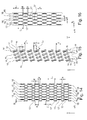
- Fig.1 shows a peripheral portion of a tread pattern of a passenger car tire, which in a known manner in the axial direction A of the tire between two formed in each other tire shoulder profile block rows 1 and 2 adjacent circumferential ribs 3, 4 and 5 and circumferential grooves 6, 7, 8 and 9 are formed.
- the circumferential grooves 6, 7, 8 and 9 extend over the entire circumference of the
- the circumferential ribs 3, 4 and 5 extend over the entire circumference of the pneumatic vehicle tire and are aligned in the circumferential direction U of the pneumatic vehicle tire.
- the profile block rows 1 and 11 extend over the entire circumference of the pneumatic vehicle tire and are aligned in the circumferential direction U.
- the circumferential groove 6 spaced in the axial direction A of the pneumatic vehicle tire trained in the left shoulder tire block row 1 of the axially adjacent peripheral rib 3.
- the profile block row 1 is in a known manner in the circumferential direction U of the pneumatic vehicle tire successively arranged profile block elements formed of known type, which are each spaced by transverse grooves 10 from each other.
- the transverse grooves 10 extend from a position outside the ground contact width T A into the circumferential groove 6.
- the profile block row 2 formed in the tire shoulder shown on the right is distributed in a known manner from around the circumference of the pneumatic vehicle tire and successively arranged profile block elements of known type, which in each case Circumferentially U are spaced by transverse grooves 11 from each other.
- the transverse grooves 11 extend from an axial position outside the ground contact width T A into the circumferential groove 9.
- the ground contact width is the width of the ground contacting part of the tread which corresponds to the static footprint according to ETRTO standards (measured at a load corresponding to 70% of the tire's load capacity given at an internal pressure of 2.5 bar and at internal pressure of 85% of 2.5 bar).
- the profile block rows 1 and 2 and the circumferential ribs 3, 4 and 5 are limited in the radial direction R of the pneumatic vehicle tire to the outside in each case by a radially outer surface 15 forming the ground contact surface.
- the circumferential grooves 6, 7, 8 and 9 are bounded in the radial direction R of the pneumatic vehicle tire in each case by a groove bottom 14 and in the axial direction A of the pneumatic vehicle tire on both sides by a groove wall, which in each case to the adjacent profile rib or profile block row forming profile element edge forms.
- the circumferential groove 9 is limited in the axial direction A to the circumferential rib 5 through a groove wall 12 and the profile block row 2 through a groove wall 13.
- the groove wall 12 forms the circumferential groove 9 directed toward rib side of the circumferential rib 5.
- the groove wall 13 forms the circumferential groove 9 directed towards edge of the profile block row 2.
- the groove wall 12 extends from the groove bottom 14 in the radial direction R outwards to the Peripheral rib 5 radially outwardly bounding radially outer surface 15.
- the groove wall 13 extends from the groove bottom 14 in the radial direction R of the pneumatic vehicle tire outward to the profile block row 2 in the radial direction R outwardly bounding radially outer surface 15th
- the patterns of elevations 17 are in the Fig. 16 . 7, 6 and 8 the example of the formation of the elevations 17 from the groove bottom 14, which extends over the entire groove bottom 14, shown in more detail.
- the patterns of protrusions in the groove walls are formed in an analogous manner.
- In the pattern of protrusions 17 are in a longitudinally rectilinear in the circumferential direction U aligned over the circumference of the tire, parallel extension lines 16 in the circumferential direction U one behind the other and arranged at a distance a from each other arranged elongated elevations 17 distributed in a circumferentially directed row over the circumference of the pneumatic vehicle tire.
- the elevations 17 are each aligned with their main extension direction in the extension direction of the circumferential groove 9 and thus in the circumferential direction U.
- the elevations 17 are formed with an extension length L 1 measured in the groove extension 14 in its main extension direction and with a maximum extension width B 1 likewise measured in the groove base 14 transversely to the main extension direction and thus transversely to the circumferential direction U.
- oblong means that the length L 1 is significantly greater than the width B 1 with (0.05 L 1 ) ⁇ B 1 ⁇ (0.2 L 1 ).
- For the extension length L 1 of the elevations 17 is in each case 8mm ⁇ L 1 ⁇ 30mm.
- the width B 1 is formed in each case with 0.8 mm ⁇ B 1 ⁇ 1.5 mm.
- the elevations 17 rise up to a height H 1 from the groove bottom 14, wherein the height H 1 is measured perpendicular to the surrounding groove bottom surface.
- the height H 1 is formed with 0.1 mm ⁇ H 1 ⁇ 0.8 mm.
- a plurality of such in the axial direction A of the tire adjacent and rectilinear in the circumferential direction U aligned extension lines 16 of rows of elevations 17 are each arranged at a distance e from each other.
- On each of these extension lines 16 are distributed over the circumference of the Anlagenluftreigens and in the circumferential direction U of the tire and thus seen in the direction of extension of the groove in rows one behind the other arranged such elevations 17 of the extension length L 1 in the circumferential direction U at a distance a from each other.
- each two in the axial direction A immediately adjacent extension lines 16 in the circumferential direction U of the pneumatic vehicle tire are offset from one another such that each arranged on the one extension line 16 radial elevation 17 in its circumferential extent at its in
- Circumferential direction front extension end respectively with a rear extension portion of the circumferential extent of a first radial elevation 17, which is formed on the directly in the axial direction A adjacent extension line 16, and at its circumferentially rearward extension end respectively with a front extension portion of the circumferential extent of a second radial elevation 17, which is likewise formed on the extension line 16 immediately adjacent in the axial direction A in the distance a measured relative to the first elevation 17 in the circumferential direction U, in each case overlapping over an extension section d.
- each elevation 17 which is formed on an extension line 16 at its front end in the circumferential direction and at its rear end in the circumferential direction in each case with radial elevations 17 to the right and radial elevations 17 of the leftmost adjacent extension line 16 over an overlap length d.
- the distance a between two circumferentially U successively formed on an extension line 16 surveys 17 is formed with 2mm ⁇ a ⁇ (0.9 L 1 ).
- the distance e between two adjacent extension lines 16 is formed with e ⁇ 5 mm.
- the overlap length d is formed with 1mm ⁇ d ⁇ L 1 .
- Fig. 13 shows an alternative embodiment in which arranged on a first extension line 16 surveys 17 each overlapped only with its front end in the circumferential direction U extension with a rear extension end of the right side axially adjacent extension line 16 formed radial elevation 17 is formed but without overlap the other extension end.
- Figure 14 shows an alternative embodiment in which, in a modification to the formation of Figure 16 are formed on each second extension row 16 instead of the elevations 17 with the extension length L 1 and the width B 1 elevations 17 'with an extension length L 1 ' and a width B 1 ', wherein the extension length L 1 ' ⁇ L 1 and the Width B 1 ' ⁇ B 1 is formed.
- Fig. 2 . 10 . 4 and 5 show an alternative embodiment with such juxtaposed extension lines 16 of such staggered rows of elevations 17, on each of which elevations 17 in the circumferential direction U of the tire are lined up one behind the other.
- this embodiment is on either side of each extension line 16 of a series of elevations 17 each parallel to the extension line 16 and thus in the direction of extension of the groove - ie in the circumferential direction U - aligned extension line 18 a series of elevations 19 distributed over the circumference of the tire, in Circumferentially U arranged elevations 19 of the extension length L 2 , the width B 2 and the extension height H 2 formed.
- an elevation 19 is in each case formed axially adjacent to an elevation 17 of an extension line 16 on the extension line 18 immediately adjacent to the extension line 16.
- This survey 19 extends - as in Figure 4 can be seen - with their entire extension length L 2 within the circumferential extension portion of the measured in the circumferential direction U of the pneumatic vehicle tire extension length L 1 of this adjacent elevation 17. This results in a repeating over the circumference of the tire pattern of Fig. 4 Surface section elements shown in which in each case on both sides of a survey 17 an extension line 16 is formed a precisely one elevation 19 on an immediately adjacent extension line 18.
- L 2 ⁇ L 1 and B 2 ⁇ B 1 for the extension length L 2 and the width B 2 , in each case L 2 ⁇ L 1 and B 2 ⁇ B 1 .
- the extension length L 1 , the width B 1 and the extension height H 1 of the elevations 17 are selected as indicated above.
- the lengths L 1 of the elevations 17 and L 2 of the elevations 19 are formed with (1/3) L 1 ⁇ L 2 ⁇ (1/2) L 1 .
- L 2 of the elevations 19 is in each case 3mm ⁇ L 2 ⁇ 10mm.
- the width B 2 is formed in each case with 0.8 mm ⁇ B 2 ⁇ 1.5 mm.
- L 1 10 mm
- L 2 5 mm
- B 1 1 mm
- B 2 0.8 mm.
- the extension height H 2 is formed with 0.1 mm ⁇ H 2 ⁇ H 1 .
- Fig. 9 shows another embodiment in which H 2 ⁇ H 1 is formed.
- Fig. 2 and 10 show an embodiment in which in each case between two adjacent extension lines 16 on a common extension line 18 formed elevations 19 over the circumference of the tire away in each case alternately either within the circumferential extension portion of a radial elevation 17 of the one axial side adjacent extension line 16 or are formed within the circumferential extension portion of a radial elevation 17 of the extension line 16 adjacent to the other axial side.
- FIGS. 11 and 12 show a further alternative pattern of the arrangement of radial elevations, in each case in the axial direction A between the extension lines 16 formed on radial elevations 17 of the extension length L 1 and to them adjacent, formed in its circumferential extent portion radial elevations 19 of the extension length L 2 additional radial projections 21 of the extension length L 3 are formed with L 1 > L 3 > L 2 .
- the radial projections 21 are formed with a width B 3 which is formed with B 2 ⁇ B 3 ⁇ B 1 .
- the extension height H 3 of the radial projections 21 is formed with H 2 ⁇ H 3 ⁇ H 1 .
- the radial elevations 17 arranged on an extension line 16 and the radial elevations 21 additionally arranged on an extension line 18 on each side of the radial elevations 17 of this extension line 16 are likewise arranged on an extension line 20 oriented rectilinearly in the circumferential direction U.
- This extension line 20 is arranged between the extension line 16 and that extension line 18, on which the projections 16 arranged on the extension line 16 in the circumferential extension section 16 are arranged next to the radial elevations 19 and thus associated with these elevations 16, respectively.
- Fig. 11 shows an embodiment in which in this sense to the elevations 17 of a first extension line 16 to be assigned extension line 20 parallel to elevation 17 adjacent elevation 21 respectively the extension line 18 of the elevations 19, which the elevations 17 of the first extension line 16 immediately adjacent extension line 16th is to be assigned.
- the elevations are 17,19,21 in the cross sections perpendicular to the direction of extension of the groove and thus perpendicular to the extension direction of the survey 17,19,21 each with a contour of two formed in a vertex S intersecting rectilinear flank lines.
- the vertex S forms the point of maximum height extension of the respective elevation 17,19,21 within this cross-sectional plane.
- Fig. 6 and Figure 16 can be found on the example of the survey 17, form the vertices S of the cross-sectional planes along the extension of the respective elevation 17,19,21 while a straight line in the circumferential direction U lying on the extension line 16 lying apex line.
- the crest line is - as in Fig. 8 can be seen - along the direction of extension of the groove formed with a curvilinear course of height, along the extension L 1 of the elevation 17, starting from the groove bottom 14 initially degressive increases to the maximum extent height H 1max of the radial elevation 17 and in the extension again up to Groove bottom decreases progressively.
Abstract
Description
Die Erfindung betrifft ein Laufstreifenprofil eines Fahrzeugreifens -insbesondere eines Fahrzeugluftreifens - mit Rillen, welche radial erhabene Profilelemente voneinander trennen, wobei die Rillen in radialer Richtung R nach innen jeweils durch einen Rillengrund und beiderseits des Rillengrundes in Richtung zum angrenzenden Profilelement hin jeweils durch eine eine Profilelementflanke bildende Rillenwand begrenzt ist, welche sich jeweils in radialer Richtung R des Reifens aus dem Rillengrund nach außen erstreckt, mit wenigstens einer Rille mit einer Haupterstreckungsrichtung, deren größte Richtungskomponente in Umfangsrichtung U des Fahrzeugreifens ausgebildet ist.The invention relates to a tread pattern of a vehicle tire - in particular a pneumatic vehicle tire - with grooves which radially separate profile elements from each other, wherein the grooves in the radial direction R in each case by a groove bottom and on both sides of the groove bottom in the direction of the adjacent profile element in each case by a profile element flank forming groove wall is limited, which extends in the radial direction R of the tire out of the groove bottom to the outside, with at least one groove having a main extension direction, the largest directional component in the circumferential direction U of the vehicle tire is formed.
Derartige Laufstreifenprofile sind bekannt. Die in Umfangsrichtung gerichteten Rillen dienen dabei hauptsächlich zur Aufnahme und zur Ableitung von Wasser beim Befahren von benässten Oberflächen. Üblicherweise sind die Rillen dabei an ihren Oberflächen möglichst glatt ausgeführt, um auf diese Weise so wenig Verwirbelungen des Wassers wie möglich zu verursachen. Allerdings entstehen im Grenzschichtbereich zur Oberfläche hin dennoch Strömungsabrisse mit Miniturbulenzen, die einer optimalen Strömung entgegenwirken.Such tread profiles are known. The circumferentially directed grooves serve mainly for receiving and discharging water when driving on wetted surfaces. Usually, the grooves are made as smooth as possible on their surfaces, so as to cause as little turbulence of the water as possible in this way. However, in the boundary layer area towards the surface, there are nevertheless stalls with mini turbulences, which counteract an optimal flow.
Es sind Ausbildungen von Rillen bekannt, bei denen über zusätzlich in den Rillenoberflächen in die Rille hinein sich erhebende Rippen ausgebildet sind, welche sich über die gesamte Erstreckung der Rille hinweg erstrecken. Hierdurch kann zwar eine Kanalisierung der Strömung verbessert werden. Eine beruhigende Wirkung auf die Strömung entfalten diese Rippen jedoch nur bedingt und dies unter relativ hohem zusätzlichem Gummivolumen innerhalb der Rille, wodurch jedoch das Aufnahmevolumens der Rille zur Aufnahme von Wasser weiter begrenzt wird. Dies begrenzt die Optimierung von Aquaplaning-Eigenschaften.Formations of grooves are known in which ribs which rise in the groove additionally in the groove surfaces are formed which extend over the entire extent of the groove. In this way, although a channeling of the flow can be improved. However, these ribs develop a calming effect on the flow only to a limited extent and this under relatively high levels additional volume of rubber within the groove, which, however, further limits the receiving volume of the groove for receiving water. This limits the optimization of aquaplaning properties.
Aus der Natur ist es bekannt, dass Haifische mit ihrer Haifischhaut eine besondere Oberfläche mit kleinen gerichteten Erhebungen, welche sich auf den Schuppen befinden, ausgebildet sind, welche dafür sorgen, dass sich die Strömung, die an der Oberfläche anliegt, beruhigt. Miniverwirbelungen, welche einen höheren Widerstand verursachen würden, werden verringert. Der Abriss der laminaren Strömung im Bereich der Grenzschicht wird verringert. Die laminare Strömung an der Oberfläche kann deutlich verlängert werden.From nature, it is known that sharks with their sharkskin a special surface with small directed elevations, which are located on the scales, are formed, which ensure that the flow that rests on the surface, calms down. Mini vortexes that would cause higher resistance are reduced. The demolition of the laminar flow in the area of the boundary layer is reduced. The laminar flow at the surface can be significantly extended.
Aus der
Aus der
Der Erfindung liegt die Aufgabe zugrunde, ein Laufstreifenprofil mit derartigen Rillen auszubilden, die ein verbessertes, störungsfreies Strömungsverhalten des Wassers in beiden Drehrichtungen des Reifens ermöglichen.The invention has for its object to form a tread pattern with such grooves, which allow an improved, trouble-free flow behavior of the water in both directions of rotation of the tire.
Die Aufgabe wird erfindungsgemäß durch die Ausbildung eines Laufstreifenprofils eines Fahrzeugreifens -insbesondere eines Fahrzeugluftreifens - mit Rillen, welche radial erhabene Profilelemente voneinander trennen, wobei die Rillen in radialer Richtung R nach innen jeweils durch einen Rillengrund und beiderseits des Rillengrundes in Richtung zum angrenzenden Profilelement hin jeweils durch eine eine Profilelementflanke bildende Rillenwand begrenzt ist, welche sich jeweils in radialer Richtung R des Reifens aus dem Rillengrund nach außen erstreckt, mit wenigstens einer Rille mit einer Haupterstreckungsrichtung, deren größte Richtungskomponente in Umfangsrichtung U des Fahrzeugreifens ausgebildet ist, gemäß den Merkmalen von Anspruch 1 gelöst, bei dem in der Oberfläche wenigstens einer Rillenwand und/oder des Rillengrundes mehrere nebeneinander angeordnete und in Erstreckungsrichtung der Rille ausgerichtete erste Reihen von in Erstreckungsrichtung der Rille hintereinander und von einander beabstandet angeordneten in die Rille ragenden länglichen Erhebungen ausgebildet sind, deren in Erstreckungsrichtung der Rille gemessene Erstreckungslänge L1 größer ist als ihre Erstreckungsbreite B1, wobei die Erhebungen einer ersten Reihe jeweils in Erstreckungsrichtung der Rille zu den Erhebungen der benachbarten ersten Reihe versetzt und unter Überlappung mit einer Erhebung - insbesondere mit zwei Erhebungen - der benachbarten ersten Reihe angeordnet sind.The object is achieved by the formation of a tread pattern of a vehicle tire - in particular a pneumatic vehicle tire - with grooves which radially separate profile elements from each other, wherein the grooves in the radial direction R in each case by a groove bottom and both sides of the groove bottom in the direction of the adjacent profile element respectively is defined by a profiled element flank forming groove wall which extends in the radial direction R of the tire out of the groove bottom to the outside, with at least one groove having a main extension direction, the largest direction component is formed in the circumferential direction U of the vehicle tire, according to the features of
Die Ausbildung ermöglicht durch die nebeneinander angeordneten, in Erstreckungsrichtung der Rille ausgebildeten ersten Reihen mit länglichen Erhebungen die Sicherstellung von leitenden Minikanälen in der Oberfläche und dadurch eine geleitete Strömung längs der Oberfläche der Rille, was sich beruhigend auf die Strömung auswirkt. Dabei ermöglicht die in Erstreckungsrichtung der Rille versetzte und überlappte Anordnung der Erhebungen der benachbarten ersten Reihen eine sichere Leitfunktion der Strömung in der Grenzschicht und die mit Abstand in Erstreckungsrichtung der Rille zueinander angeordnete Ausbildung einzelner Erhebungen innerhalb der ersten Reihen eine zusätzliche Beruhigung der Strömung. Der Effekt ist dabei in beiden Durchströmungsrichtungen der Rille und somit in beiden Drehrichtungen des Reifens möglich. Wie bei der Haifischhaut in der Natur wird durch diese Ausbildung eine Art Schuppenstruktur mit inselartigen Schuppen mit einer Strömungsleitfunktion über die gesamte Erstreckung der Reihen umgesetzt. Die Entstehung von Miniturbulenzen aufgrund von frühzeitigem Strömungsabriss kann reduziert und die laminare Strömung länger aufrecht erhalten werden. Diese Ausbildung mit den ersten Reihen mit in Erstreckungsrichtung voneinander beabstandenden Erhebungen ermöglicht dabei die Umsetzung der strömungsgünstigen Ausbildung mit relativ geringem in die Rille eingreifenden zusätzlichen Gummivolumen, wodurch unter anderem auch der Einfluss auf die Aufnahmekapazität zur Aufnahme von Wasser minimiert werden kann.The training allows by the juxtaposed, formed in the extension direction of the groove first rows of elongated elevations, the assurance of conductive mini-channels in the surface and thereby a guided flow along the surface of the groove, which has a calming effect on the flow. In this case, the offset in the direction of extension of the groove and overlapped arrangement of the elevations of the adjacent first rows allows a secure guiding function of the flow in the boundary layer and the spacing in the direction of extension of the groove to each other arranged formation of individual elevations within the first rows an additional calming of the flow. The effect is possible in both flow directions of the groove and thus in both directions of rotation of the tire. As with the sharkskin in nature, this design provides a kind of scale structure with island-like scales with a flow-guiding function over the entire extension of the rows. Miniturbulence due to premature stall can be reduced and laminar flow maintained longer. This training with the first rows of surveys spaced apart in the extension direction allows the implementation of streamlined training with relatively little engaging in the groove additional rubber volume, which among other things, the influence on the absorption capacity for receiving water can be minimized.
Besonders vorteilhaft ist die Ausbildung eines Laufstreifenprofils gemäß den Merkmalen von Anspruch 2, bei dem beiderseits einer ersten Reihe zwischen der ersten Reihe und der benachbarten ersten Reihe jeweils eine in Erstreckungsrichtung der Rille ausgerichtete zweite Reihe von in Erstreckungsrichtung der Rille hintereinander und von einander beabstandet angeordneten in die Rille ragenden länglichen Erhebungen ausgebildet ist, deren in Erstreckungsrichtung der Rille gemessene Erstreckungslänge L2 größer ist als ihre Erstreckungsbreite B2 mit L2< L1 und mit B2< B1, wobei längs der Erstreckungsrichtung der Rille innerhalb des Erstreckungsbereichs einer jeden Erhebung der ersten Reihe jeweils eine Erhebung der zu ihr benachbarten zweiten Reihe mit ihrer vollständigen Erstreckungslänge L2 ausgebildet ist. Hierdurch kann in einfacher Weise eine Strömungsoptimierung auch bei unterschiedlichen Fahrgeschwindigkeiten gezielt eingestellt werden.Particularly advantageous is the formation of a tread strip according to the features of
Besonders vorteilhaft ist die Ausbildung eines Laufstreifenprofils gemäß den Merkmalen von Anspruch 3, bei dem diejenigen zu zwei benachbarten ersten Reihen jeweils zugeordneten zweiten Reihen, welche zwischen den beiden ersten Reihen angeordnet sind, auf einer gemeinsamen Erstreckungslinie ausgebildet sind, wobei auf der Erstreckungslinie die Erhebungen der zu der einen ersten Reihe zuzuordnenden zweiten Reihe und die Erhebungen der zu der anderen ersten Reihe zuzuordnenden zweiten Reihe in alternierender Abfolge angeordnet sind. Hierdurch kann ermöglicht werden, dass die Reihen bei verschiedenen Geschwindigkeiten in Richtung der Rillenerstreckung gesehen eine weiter optimierte Strömungsleitfunktion bei weiter minimierter Störwirkung entfalten können.Particularly advantageous is the formation of a tread pattern according to the features of
Besonders vorteilhaft ist die Ausbildung eines Laufstreifenprofils gemäß den Merkmalen von Anspruch 4, bei dem zwischen erster Reihe und der ihr zugeordneten zweiten Reihe jeweils eine weitere in Erstreckungsrichtung der Rille ausgerichtete dritte Reihe von in Erstreckungsrichtung der Rille hintereinander und von einander beabstandet angeordneten, in die Rille ragenden länglichen Erhebungen ausgebildet ist, deren in Erstreckungsrichtung der Rille gemessene Erstreckungslänge L3 größer ist als ihre Erstreckungsbreite B3 mit L2≤ L3 ≤L1 - insbesondere mit L2< L3 <L1 - und mit B2≤ B3 ≤B1- insbesondere mit B2< B3 <B1-, wobei in Erstreckungsrichtung der Rille innerhalb des Erstreckungsbereichs einer jeden Erhebung der ersten Reihe jeweils eine Erhebung der zu ihr benachbarten dritten Reihe mit ihrer vollständigen Erstreckungslänge L3 ausgebildet ist. Hierdurch kann in einfacher Weise eine weitere Strömungsoptimierung auch bei unterschiedlichen Fahrgeschwindigkeiten gezielt eingestellt werden.Particularly advantageous is the formation of a tread strip according to the features of
Besonders vorteilhaft ist die Ausbildung eines Laufstreifenprofils gemäß den Merkmalen von Anspruch 5, bei dem die Erstreckungslänge L1 mit 8mm≤ L1≤30mm und die Erstreckungsbreite B1 mit 0,8mm≤ B1≤1,5mm ausgebildet ist. Dies ermöglicht eine optimale, funktionsorientierte Auslegung auf die relevanten Strömungsgeschwindigkeiten in derartigen Laufstreifenprofilen.Particularly advantageous is the formation of a tread pattern according to the features of
Besonders vorteilhaft ist die Ausbildung eines Laufstreifenprofils gemäß den Merkmalen von Anspruch 6, bei dem die Erstreckungsbreite B1 mit (0,05 L1)≤ B1≤(0,2 L1) ausgebildet ist. Hierdurch kann in einfacher Weise eine bestimmte Strömungsrichtung gezielt eingestellt werden.Particularly advantageous is the formation of a tread strip according to the features of
Besonders vorteilhaft ist die Ausbildung eines Laufstreifenprofils gemäß den Merkmalen von Anspruch 7, bei dem die Erstreckungslänge L2 mit 3mm≤ L2≤10mm und die Erstreckungsbreite B2 mit 0,8mm≤ B2≤1,5mm ausgebildet ist. Dies ermöglicht eine optimale funktionsorientierte Ausrichtung der Erhebungen der zweiten Reihen in Erstreckungsrichtung der Rille, wodurch eine gezielte Einstellung der gewünschten Strömungsrichtung begünstigt wird.Particularly advantageous is the formation of a tread pattern according to the features of
Besonders vorteilhaft ist die Ausbildung eines Laufstreifenprofils gemäß den Merkmalen von Anspruch 8, bei dem die Erstreckungsbreite B2 mit (0,05 L2)≤ B2≤(0,2 L2) ausgebildet ist. Hierdurch kann in einfacher Weise eine bestimmte Strömungsrichtung gezielt eingestellt werden.Particularly advantageous is the formation of a tread pattern according to the features of
Besonders vorteilhaft ist die Ausbildung eines Laufstreifenprofils gemäß den Merkmalen von Anspruch 9, bei dem die Erstreckungslänge L2 mit (1/3) L1 ≤ L2≤ (1/2) L1 ausgebildet ist.Particularly advantageous is the formation of a tread pattern according to the features of
Besonders vorteilhaft ist die Ausbildung eines Laufstreifenprofils gemäß den Merkmalen von Anspruch 10, bei dem die senkrecht zur Oberfläche der Rillenwand bzw. des Rillengrundes gemessene maximale Erstreckungshöhe h der Erhebungen mit 0,05mm ≤h ≤0,8mm - insbesondere mit 0,1mm ≤h ≤0,3mm - ausgebildet ist. Hierdurch kann die gewünschte Leitfunktion der Erhebungen in einfacher Weise bei Nutzung bekannter Formfertigungsmethoden umgesetzt werden.Particularly advantageous is the formation of a tread pattern according to the features of
Besonders vorteilhaft ist die Ausbildung eines Laufstreifenprofils gemäß den Merkmalen von Anspruch 11, bei dem die senkrecht zur Oberfläche der Rillenwand bzw. des Rillengrundes gemessene maximale Erstreckungshöhe h der Erhebungen der ersten Reihe größer ist als die der anderen Reihen. Hierdurch kann in einfacher Weise eine Strömungsoptimierung auch bei unterschiedlichen Fahrgeschwindigkeiten gezielt eingestellt werden.Particularly advantageous is the formation of a tread pattern according to the features of
Besonders vorteilhaft ist die Ausbildung eines Laufstreifenprofils gemäß den Merkmalen von Anspruch 12, wobei die Erhebungen in ihren senkrecht zur Längserstreckungsrichtung ausgebildeten Querschnitten mit einer Oberflächenkontur aus zwei sich in einem Scheitelpunkt schneidenden, geradlinigen Erhebungsflanken ausgebildet sind. Dies begünstigt eine gutes leitendes Eingreifen der Erhebungen in die Strömung bei einfacher Fertigung.Particularly advantageous is the formation of a tread pattern according to the features of
Besonders vorteilhaft ist die Ausbildung eines Laufstreifenprofils gemäß den Merkmalen von Anspruch 13, wobei die Erhebungen mit einer längs ihrer Längenerstreckung veränderten Erstreckungshöhe ausgebildet sind, wobei insbesondere die Erstreckungshöhe ausgehend von einem Erstreckungsende der Erhebung in Richtung zum anderen Erstreckungsende der Erhebung degressiv bis zur Position der maximalen Erstreckungshöhe zu- und im weiteren Erstreckungsbereich bis zum Erstreckungsende progressiv abnehmend ausgebildet ist. Der hierdurch etwas bedingte etwas abgerundete Verlauf der Erstreckungshöhe begünstigt eine hohe Haltbarkeit im Reifen.Particularly advantageous is the formation of a tread pattern according to the features of
Die Erfindung wird im Folgenden an Hand der in den
- Fig.1
- Draufsicht auf ein Laufstreifenprofil eines PKW-Fahrzeugluftreifens,
- Fig.2
- eine vergrößerte Detailansicht des Details II von
Fig.1 mit Draufsicht auf eine Umfangsrille mit Rillengrund, in welchem mehrere Reihen von hintereinander angeordneten Erhebungen ausgebildet sind, - Fig.3
- eine Querschnittdarstellung der Rille von
Fig.2 im Schnitt III-III vonFig.1 , - Fig.4
- eine vergrößerte Darstellung der in axialer Richtung des Reifens nebeneinander angeordneten Erhebungen unterschiedlicher, nebeneinander angeordneter Reihen von
Fig.2 , - Fig.5
- eine Querschnittdarstellung des Rillengrundes gemäß Schnitt V-V von
Fig.4 , - Fig.6
- eine vergrößerte Darstellung einer Erhebung des Rillengrundes von
Fig.2 undFig.4 in Draufsicht, - Fig.7
- eine Querschnittdarstellung des Rillengrundes gemäß Schnitt VII-VII von
Fig.6 , - Fig.8
- eine Querschnittdarstellung des Rillengrundes gemäß Schnitt VIII-VIII von
Fig.6 , - Fig.9
- eine Querschnittdarstellung des Rillengrundes von
Fig.4 gemäß Schnitt V-V vonFig.4 in alternativer Ausführung der Erhebungen, - Fig.10
- eine Darstellung des in
Fig.2 ausgebildeten Musters an nebeneinander angeordneten Reihen von Erhebungen, - Fig.11
- eine Darstellung eines alternativen Musters von nebeneinander angeordneten Reihen von Erhebungen,
- Fig.12
- vergrößerter Ausschnitt von quer zur Rillenerstreckung nebeneinander angeordneten Erhebungen des in
Fig.11 dargestellten Musters zur Erläuterung der Anordnung, - Fig.13
- eine Darstellung einer weiteren alternativen Ausbildung eines Musters von nebeneinander angeordneten Reihen von Erhebungen,
- Fig.14
- eine Darstellung einer weiteren alternativen Ausbildung eines Musters von nebeneinander angeordneten Reihen von Erhebungen,
- Fig.15
- eine Darstellung einer weiteren alternativen Ausbildung eines Musters von nebeneinander angeordneten Reihen von Erhebungen und
- Fig.16
- eine Darstellung einer weiteren alternativen Ausbildung eines Musters von nebeneinander angeordneten Reihen von Erhebungen.
- Fig.1
- Top view of a tread pattern of a passenger car pneumatic tire,
- Fig.2
- an enlarged detail view of the detail II of
Fig.1 with a plan view of a circumferential groove with groove bottom, in which a plurality of rows of successively arranged elevations are formed, - Figure 3
- a cross-sectional view of the groove of
Fig.2 in section III-III ofFig.1 . - Figure 4
- an enlarged view of the arranged in the axial direction of the tire adjacent elevations of different juxtaposed rows of
Fig.2 . - Figure 5
- a cross-sectional view of the groove bottom according to section VV of
Figure 4 . - Figure 6
- an enlarged view of a survey of the groove bottom of
Fig.2 andFigure 4 in plan view, - Figure 7
- a cross-sectional view of the groove bottom according to section VII-VII of
Figure 6 . - Figure 8
- a cross-sectional view of the groove bottom according to section VIII-VIII of
Figure 6 . - Figure 9
- a cross-sectional view of the groove bottom of
Figure 4 according to section VV ofFigure 4 in an alternative version of the surveys, - Figure 10
- a representation of the in
Fig.2 formed pattern on adjacent rows of elevations, - Figure 11
- a representation of an alternative pattern of juxtaposed rows of surveys,
- Figure 12
- enlarged section of transverse to the groove extension juxtaposed elevations of in
Figure 11 illustrated pattern for explaining the arrangement, - Figure 13
- a representation of a further alternative embodiment of a pattern of juxtaposed rows of surveys,
- Figure 14
- a representation of a further alternative embodiment of a pattern of juxtaposed rows of surveys,
- Figure 15
- a representation of another alternative embodiment of a pattern of juxtaposed rows of surveys and
- Figure 16
- a representation of another alternative embodiment of a pattern of juxtaposed rows of surveys.
Fahrzeugluftreifens und sind in Umfangsrichtung U des Fahrzeugluftreifens ausgerichtet. Die Umfangsrippen 3, 4 und 5 erstrecken sich über den gesamten Umfang des Fahrzeugluftreifens und sind in Umfangsrichtung U des Fahrzeugluftreifens ausgerichtet. Die Profilblockreihen 1 und 11erstrecken sich über den gesamten Umfang des Fahrzeugluftreifens und sind in Umfangsrichtung U ausgerichtet. Die Umfangsrille 6 beabstandet in axialer Richtung A des Fahrzeugluftreifens die in der links dargestellten Reifenschulter ausgebildete Profilblockreihe 1 von der axial benachbarten Umfangsrippe 3. Die Umfangsrille 7 beabstandet in axialer Richtung A des Fahrzeugluftreifens die Umfangsrippe 3 von der axial benachbarten Umfangsrippe 4. Die Umfangsrille 8 beabstandet in axialer Richtung A die Umfangsrippe 4 von der axial benachbarten Umfangsrippe 5. Die Umfangsrille 9 beabstandet in axialer Richtung A des Fahrzeugluftreifens die Umfangsrippe 5 von der axial benachbarten Profilblockreihe 2. Die Profilblockreihe 1 ist in bekannter Weise aus in Umfangsrichtung U des Fahrzeugluftreifens hintereinander angeordneten Profilblockelementen bekannter Art ausgebildet, welche jeweils durch Querrillen 10 voneinander beabstandet sind. Die Querrillen 10 erstrecken dabei von einer Position außerhalb der Bodenaufstandsbreite TA bis in die Umfangsrille 6. Die in der rechts dargestellten Reifenschulter ausgebildete Profilblockreihe 2 ist in bekannter Weise aus über den Umfang des Fahrzeugluftreifens verteilt und hintereinander angeordneten Profilblockelementen bekannter Art ausgebildet, welche jeweils in Umfangsrichtung U durch Querrillen 11 voneinander beabstandet sind. Die Querrillen 11 erstrecken sich von einer axialen Position außerhalb der Bodenaufstandsbreite TA bis in die Umfangsrille 9.Pneumatic vehicle tire and are aligned in the circumferential direction U of the pneumatic vehicle tire. The
Die Bodenaufstandsbreite ist die Breite des den Boden berührenden Teils des Laufstreifens, welcher dem statisch ermittelten Footprint gemäß E.T.R.T.O.-Standards (gemessen bei einer Last, welche 70 % der bei einem Innendruck von 2,5 bar gegebenen Tragfähigkeit des Reifens entspricht, und bei einem Innendruck von 85 % von 2,5 bar) entspricht.The ground contact width is the width of the ground contacting part of the tread which corresponds to the static footprint according to ETRTO standards (measured at a load corresponding to 70% of the tire's load capacity given at an internal pressure of 2.5 bar and at internal pressure of 85% of 2.5 bar).
Die Profilblockreihen 1 und 2 sowie die Umfangsrippen 3, 4 und 5 sind in radialer Richtung R des Fahrzeugluftreifens nach außen hin jeweils durch eine die Bodenkontaktoberfläche bildende radial äußere Oberfläche 15 begrenzt.The
Die Umfangsrillen 6, 7, 8 und 9 sind in radialer Richtung R des Fahrzeugluftreifens nach innen hin jeweils durch einen Rillengrund 14 und in axialer Richtung A des Fahrzeugluftreifens zu beiden Seiten hin jeweils durch eine Rillenwand begrenzt, welche jeweils die zur angrenzenden Profilrippe bzw. Profilblockreihe bildende Profilelementflanke bildet.The
Wie in den
Wie in den
Die Muster von Erhebungen 17 sind in den
Für die Erstreckungslänge L1 der Erhebungen 17 gilt jeweils 8mm ≤ L1 ≤ 30mm. Die Breite B1 ist jeweils mit 0,8 mm ≤ B1≤ 1,5 mm ausgebildet.For the extension length L 1 of the
Die Erhebungen 17 erheben sich dabei bis in eine Höhe H1 aus dem Rillengrund 14, wobei die Höhe H1 senkrecht zu der umgebenen Rillengrundoberfläche gemessen wird. Die Höhe H1 ist mit 0,1 mm ≤ H1 ≤ 0,8 mm ausgebildet. In besonderer Ausführung ist die Höhe H1 mit 0,2 mm ≤ H1 ≤ 0,3 mm, beispielsweise mit H1 = 0,3 mm ausgebildet.The
Wie in
Umfangsrichtung vorderen Erstreckungsende jeweils mit einem hinteren Erstreckungsabschnitt der Umfangserstreckung einer ersten radialen Erhebung 17, welche auf der unmittelbar in axialer Richtung A benachbarten Erstreckungslinie 16 ausgebildet ist, und an ihrem in Umfangsrichtung hinteren Erstreckungsende jeweils mit einem vorderen Erstreckungsabschnitt der Umfangserstreckung einer zweiten radialen Erhebung 17, welche ebenfalls auf der unmittelbar in axialer Richtung A benachbarten Erstreckungslinie 16 im in Umfangsrichtung U gemessenen Abstand a zur ersten Erhebung 17 ausgebildet ist, jeweils über einen Erstreckungsabschnitt d überlappt. In dem in
Der Abstand a zwischen zwei in Umfangsrichtung U hintereinander auf einer Erstreckungslinie 16 ausgebildeten Erhebungen 17 ist mit 2mm ≤ a ≤ (0,9 L1) ausgebildet.The distance a between two circumferentially U successively formed on an
Der Abstand e zwischen zwei benachbarten Erstreckungslinien 16 ist mit e ≤ 5 mm ausgebildet.The distance e between two
Die Überlappungslänge d ist mit 1mm ≤ d < L1 ausgebildet.The overlap length d is formed with 1mm ≦ d <L 1 .
Die
Die Erstreckungslänge L1, die Breite B1 und die Erstreckunghöhe H1 der Erhebungen 17 sind wie oben angegeben gewählt. Die Längen L1 der Erhebungen 17 und L2 der Erhebungen 19 sind dabei mit (1/3) L1 ≤ L2 ≤ (1/2) L1 ausgebildet.The extension length L 1 , the width B 1 and the extension height H 1 of the
Für die Erstreckungslänge L2 der Erhebungen 19 gilt jeweils 3mm ≤ L2 ≤ 10mm. Die Breite B2 ist jeweils mit 0,8 mm ≤ B2≤ 1,5 mm ausgebildet. Beispielsweise ist L1 = 10 mm, L2 = 5 mm, B1 = 1 mm und B2 = 0,8 mm.For the extension length L 2 of the
Die Erstreckungshöhe H2 ist mit 0,1mm ≤ H2 ≤ H1 ausgebildet.The extension height H 2 is formed with 0.1 mm ≦ H 2 ≦ H 1 .
Die
Die zwischen den auf einer Erstreckungslinie 16 angeordneten radialen Erhebungen 17 und den beiderseits der radialen Erhebungen 17 dieser Erstreckungslinie 16 jeweils auf einer Erstreckungslinie 18 angeordneten radialen Erhebungen 19 zusätzlich angeordneten radialen Erhebungen 21 sind dabei ebenfalls auf einer geradlinig in Umfangsrichtung U ausgerichteten Erstreckungslinie 20 angeordnet. Diese Erstreckungslinie 20 ist dabei zwischen der Erstreckungslinie 16 und derjenigen Erstreckungslinie 18 angeordnet, auf welcher die im Umfangserstreckungsabschnitt der auf der Erstreckungslinie 16 angeordneten Erhebungen 16 nächstliegend angeordneten radialen Erhebungen 19 ausgebildet und somit diesen Erhebungen 16 jeweils zuzuordnen sind.The
Wie in
Wie in
Wie beispielsweise der
- 11
- ProfilblockreiheProfile block row
- 22
- ProfilblockreiheProfile block row
- 33
- Profilrippeprofile rib
- 44
- Profilrippeprofile rib
- 55
- Profilrippeprofile rib
- 66
- Umfangsrillecircumferential groove
- 77
- Umfangsrillecircumferential groove
- 88th
- Umfangsrillecircumferential groove
- 99
- Umfangsrillecircumferential groove
- 1010
- Querrilletransverse groove
- 1111
- Querrilletransverse groove
- 1212
- Rillenwandgroove wall
- 1313
- Rillenwandgroove wall
- 1414
- Rillengrundgroove bottom
- 1515
- Radial äußere OberflächeRadially outer surface
- 1616
- Reihenlinienumber line
- 1717
- Erhebungsurvey
- 1818
- Reihenlinienumber line
- 1919
- Erhebungsurvey
- 2020
- Reihenlinienumber line
- 2121
- Erhebungsurvey
Claims (13)
dadurch gekennzeichnet,
dass in der Oberfläche wenigstens einer Rillenwand (12,13) und/oder des Rillengrundes (14) mehrere nebeneinander angeordnete und in Erstreckungsrichtung der Rille (9) ausgerichtete erste Reihen (16) von in Erstreckungsrichtung der Rille (9) hintereinander und von einander beabstandet angeordneten in die Rille (9) ragenden länglichen Erhebungen (17) ausgebildet sind, deren in Erstreckungsrichtung der Rille (9) gemessene Erstreckungslänge L1 größer ist als ihre Erstreckungsbreite B1, wobei die Erhebungen (17) einer ersten Reihe (16) jeweils in Erstreckungsrichtung der Rille (9) zu den Erhebungen (17) der benachbarten ersten Reihe (16) versetzt und unter Überlappung mit einer Erhebung (17)- insbesondere mit zwei Erhebungen (17) - der benachbarten ersten Reihe (16) angeordnet sind.Tread pattern of a vehicle tire - in particular a pneumatic vehicle tire - with grooves (6,7,8,9) which radially separate profile elements (1,3,4,5,2) separated from each other, said grooves (6,7,8,9) in the radial direction R inward in each case by a groove bottom (14) and on both sides of the groove bottom (14) in the direction of the adjacent profile element (1,3,4,5,2) towards each bounded by a profile element flank forming groove wall (12,13) is, which extends in the radial direction R of the tire out of the groove bottom (14) to the outside, with at least one groove (9) with a main extension direction, the largest direction component is formed in the circumferential direction U of the vehicle tire,
characterized,
that in the surface of at least one groove wall (12,13) and / or the groove bottom (14) a plurality juxtaposed and in the extension direction of the groove (9) aligned first rows (16) of the extension direction of the groove (9) one behind the other and from each other arranged in the groove (9) projecting elongated elevations (17) are formed whose measured in the extension direction of the groove (9) extension length L 1 is greater than its extension width B 1 , the elevations (17) of a first row (16) respectively in Extending direction of the groove (9) to the elevations (17) of the adjacent first row (16) offset and overlapping with a survey (17) - in particular with two elevations (17) - the adjacent first row (16) are arranged.
bei dem beiderseits einer ersten Reihe (16) zwischen der ersten Reihe (16) und der benachbarten ersten Reihe (16) jeweils eine in Erstreckungsrichtung der Rille (9) ausgerichtete zweite Reihe (18) von in Erstreckungsrichtung der Rille (9) hintereinander und von einander beabstandet angeordneten in die Rille (9) ragenden länglichen Erhebungen (19) ausgebildet ist, deren in Erstreckungsrichtung der Rille (9) gemessene Erstreckungslänge L2 größer ist als ihre Erstreckungsbreite B2 mit L2< L1 und mit B2< B1, wobei längs der Erstreckungsrichtung der Rille (9) innerhalb des Erstreckungsbereichs einer jeden Erhebung (17) der ersten Reihe (16) jeweils eine Erhebung (19) der zu ihr benachbarten zweiten Reihe (18) mit ihrer vollständigen Erstreckungslänge L2 ausgebildet ist.Tread pattern according to the features of claim 1,
in which on both sides of a first row (16) between the first row (16) and the adjacent first row (16) each one in the extension direction of the groove (9) aligned second row (18) of the direction of extension of the groove (9) in a row and from formed spaced apart in the groove (9) projecting elongated elevations (19) is formed, whose direction of extension of the groove (9) measured extension length L 2 is greater than its extension width B 2 with L 2 <L 1 and with B 2 <B 1 , wherein along the extension direction of the groove (9) within the extension range of each elevation (17) of the first row ( 16) is formed in each case a survey (19) of its adjacent second row (18) with its full extension length L 2 .
bei dem diejenigen zu zwei benachbarten ersten Reihen (16) jeweils zugeordneten zweiten Reihen (18), welche zwischen den beiden ersten Reihen (16) angeordnet sind, auf einer gemeinsamen Erstreckungslinie (18) ausgebildet sind, wobei auf der Erstreckungslinie (18) die Erhebungen (19) der zu der einen ersten Reihe (16) zuzuordnenden zweiten Reihe (17) und die Erhebungen (19) der zu der anderen ersten Reihe (16) zuzuordnenden zweiten Reihe (18) in alternierender Abfolge angeordnet sind.Tread pattern according to the features of claim 2,
in which those two adjacent first rows (16) of respectively associated second rows (18) which are arranged between the two first rows (16) are formed on a common extension line (18), wherein on the extension line (18) the elevations (19) of the first row (16) to be assigned to the second row (17) and the elevations (19) of the second row (18) to be assigned to the second row (18) are arranged in an alternating sequence.
bei dem zwischen erster Reihe (16) und der ihr zugeordneten zweiten Reihe (18) jeweils eine weitere in Erstreckungsrichtung der Rille (9) ausgerichtete dritte Reihe (20) von in Erstreckungsrichtung der Rille (9) hintereinander und von einander beabstandet angeordneten, in die Rille (9) ragenden länglichen Erhebungen (21) ausgebildet ist, deren in Erstreckungsrichtung der Rille (9) gemessene Erstreckungslänge L3 größer ist als ihre Erstreckungsbreite B3 mit L2≤ L3 ≤L1 -insbesondere mit L2< L3 <L1 - und mit B2≤ B3 ≤B1- insbesondere mit B2< B3 <B1-, wobei in Erstreckungsrichtung der Rille (9) innerhalb des Erstreckungsbereichs einer jeden Erhebung (17) der ersten Reihe (16) jeweils eine Erhebung (21) der zu ihr benachbarten dritten Reihe (20) mit ihrer vollständigen Erstreckungslänge L3 ausgebildet ist.Tread pattern according to the features of claim 2 or 3,
in the between the first row (16) and its associated second row (18) each arranged in the extension direction of the groove (9) aligned third row (20) of the direction of extension of the groove (9) behind the other and spaced from each other, in the Groove (9) protruding elongated protrusions (21) is formed, measured in the extension direction of the groove (9) extension length L 3 is greater than its extension width B 3 with L 2 ≤ L 3 ≤L 1 - in particular with L 2 <L 3 < L 1 - and with B 2 ≤ B 3 ≤B 1 - in particular with B 2 <B 3 <B 1 -, wherein in the extension direction of the groove (9) within the extension range of each elevation (17) of the first row (16) respectively an elevation (21) of the adjacent third row (20) is formed with its full extension length L 3 .
bei dem die Erstreckungslänge L1 mit 8mm≤L1≤30mm und die Erstreckungsbreite B1 mit 0,8mm≤B1≤1,5mm ausgebildet ist.Tread pattern according to the features of one or more of the preceding claims,
in which the extension length L 1 with 8mm≤L 1 ≤30mm and the extension width B 1 is formed with 0.8mm≤B 1 ≤1.5mm.
bei dem die Erstreckungsbreite B1 mit (0,05 L1)≤ B1≤(0,2 L1) ausgebildet ist.Tread pattern according to the features of one or more of the preceding claims,
in which the extension width B 1 is formed with (0.05 L 1 ) ≦ B 1 ≦ (0.2 L 1 ).
bei dem die Erstreckungslänge L2 mit 3mm≤ L2≤10mm und die Erstreckungsbreite B2 mit 0,8mm≤ B2≤1,5mm ausgebildet ist.Tread pattern according to the features of one or more of claims 2 to 6,
wherein the extending length L 2 with L 2 3mm≤ ≤10mm and the extension of width B is formed with 0,8mm≤ B 2 ≤1,5mm. 2
bei dem die Erstreckungsbreite B2 mit (0,05 L2)≤ B2≤(0,2 L2) ausgebildet ist.Tread pattern according to the features of one or more of claims 2 to 7,
in which the extension width B 2 is formed with (0.05 L 2 ) ≦ B 2 ≦ (0.2 L 2 ).
bei dem die Erstreckungslänge L2 mit (1/3) L1 ≤ L2≤ (1/2) L1 ausgebildet ist.Tread pattern according to the features of one or more of claims 2 to 7,
wherein the extension length L 2 is formed with (1/3) L 1 ≦ L 2 ≦ (1/2) L 1 .
bei dem die senkrecht zur Oberfläche der Rillenwand (12,13) bzw. des Rillengrundes (14) gemessene maximale Erstreckungshöhe H der Erhebungen (17) mit 0,05mm <H ≤0,8mm - insbesondere mit 0,1mm <H ≤0,3mm - ausgebildet ist.Tread pattern according to the features of one or more of the preceding claims,
in which the maximum extension height H of the elevations (17) measured perpendicular to the surface of the groove wall (12, 13) or of the groove bottom (14) is 0.05 mm ≦ H ≦ 0.8 mm, in particular 0.1 mm ≦ H ≦ 0.degree. 3mm - is formed.
bei dem die senkrecht zur Oberfläche der Rillenwand (12,13) bzw. des Rillengrundes (14) gemessene maximale Erstreckungshöhe h der Erhebungen (17) der ersten Reihe (16) größer ist als die der anderen Reihen (18,20).Tread pattern according to the features of one or more of claims 2 to 10,
in which the maximum extension height h of the elevations (17) of the first row (16) measured perpendicular to the surface of the groove wall (12, 13) or of the groove bottom (14) is greater than that of the other rows (18, 20).
wobei die Erhebungen (17) in ihren senkrecht zur Längserstreckungsrichtung ausgebildeten Querschnitten mit einer Oberflächenkontur aus zwei sich in einem Scheitelpunkt S schneidenden, geradlinigen Erhebungsflanken ausgebildet sind.Tread pattern according to the features of one or more of the preceding claims,
wherein the elevations (17) are formed in their perpendicular to the longitudinal direction formed cross-sections with a surface contour of two intersecting in a vertex S, rectilinear elevation flanks.
wobei die Erhebungen (17) mit einer längs ihrer Längenerstreckung veränderten Erstreckungshöhe ausgebildet sind,
wobei insbesondere die Erstreckungshöhe ausgehend von einem Erstreckungsende der Erhebung (17) in Richtung zum anderen Erstreckungsende der Erhebung (17) degressiv bis zur Position der maximalen Erstreckungshöhe zu- und im weiteren Erstreckungbereich bis zum Erstreckungsende progressiv abnehmend ausgebildet ist.Tread pattern according to the features of one of the preceding claims,
wherein the elevations (17) are formed with an extent height which is changed along their length extension,
wherein in particular the extension height, starting from an extension end of the elevation (17) toward the other extension end of the elevation (17), is degressive to the position of the maximum extension height and progressively decreasing in the further extension range to the extension end.
Applications Claiming Priority (1)
| Application Number | Priority Date | Filing Date | Title |
|---|---|---|---|
| DE102012105300A DE102012105300A1 (en) | 2012-06-19 | 2012-06-19 | Vehicle tires |
Publications (2)
| Publication Number | Publication Date |
|---|---|
| EP2676815A1 true EP2676815A1 (en) | 2013-12-25 |
| EP2676815B1 EP2676815B1 (en) | 2016-08-31 |
Family
ID=48534260
Family Applications (1)
| Application Number | Title | Priority Date | Filing Date |
|---|---|---|---|
| EP13169827.6A Active EP2676815B1 (en) | 2012-06-19 | 2013-05-30 | Pneumatic tyre for a vehicle |
Country Status (2)
| Country | Link |
|---|---|
| EP (1) | EP2676815B1 (en) |
| DE (1) | DE102012105300A1 (en) |
Cited By (4)
| Publication number | Priority date | Publication date | Assignee | Title |
|---|---|---|---|---|
| USD771551S1 (en) | 2015-09-29 | 2016-11-15 | Cooper Tire & Rubber Company | Tire tread |
| EP3100873A1 (en) * | 2015-06-01 | 2016-12-07 | Continental Reifen Deutschland GmbH | Pneumatic tyres for a vehicle |
| EP3102438A4 (en) * | 2014-02-04 | 2017-09-20 | Bridgestone Americas Tire Operations, LLC | Rounded stone ejectors |
| CN110406328A (en) * | 2019-06-13 | 2019-11-05 | 青岛森麒麟轮胎股份有限公司 | Convenient for the tread groove structure and tire of draining |
Families Citing this family (1)
| Publication number | Priority date | Publication date | Assignee | Title |
|---|---|---|---|---|
| DE102018219148A1 (en) | 2018-11-09 | 2020-05-14 | Continental Reifen Deutschland Gmbh | Pneumatic vehicle tires |
Citations (5)
| Publication number | Priority date | Publication date | Assignee | Title |
|---|---|---|---|---|
| JP2002036820A (en) | 2000-07-24 | 2002-02-06 | Bridgestone Corp | Pneumatic tire |
| JP2006056480A (en) * | 2004-08-23 | 2006-03-02 | Toyo Tire & Rubber Co Ltd | Pneumatic tire |
| DE102004052319A1 (en) | 2004-10-28 | 2006-05-11 | Continental Aktiengesellschaft | Vehicle tire, especially pneumatic tire, having surface elements in scale-like arrangement, overlayed by parallel grooves, to improve aquaplaning properties on wet roads |
| EP2011672A1 (en) * | 2007-07-02 | 2009-01-07 | Kumho Tire Co., Inc. | Pneumatic tire with symmetrical tread pattern |
| WO2010070690A1 (en) * | 2008-12-19 | 2010-06-24 | Pirelli Tyre S.P.A. | Heavy, load pneumatic tire |
-
2012
- 2012-06-19 DE DE102012105300A patent/DE102012105300A1/en not_active Withdrawn
-
2013
- 2013-05-30 EP EP13169827.6A patent/EP2676815B1/en active Active
Patent Citations (5)
| Publication number | Priority date | Publication date | Assignee | Title |
|---|---|---|---|---|
| JP2002036820A (en) | 2000-07-24 | 2002-02-06 | Bridgestone Corp | Pneumatic tire |
| JP2006056480A (en) * | 2004-08-23 | 2006-03-02 | Toyo Tire & Rubber Co Ltd | Pneumatic tire |
| DE102004052319A1 (en) | 2004-10-28 | 2006-05-11 | Continental Aktiengesellschaft | Vehicle tire, especially pneumatic tire, having surface elements in scale-like arrangement, overlayed by parallel grooves, to improve aquaplaning properties on wet roads |
| EP2011672A1 (en) * | 2007-07-02 | 2009-01-07 | Kumho Tire Co., Inc. | Pneumatic tire with symmetrical tread pattern |
| WO2010070690A1 (en) * | 2008-12-19 | 2010-06-24 | Pirelli Tyre S.P.A. | Heavy, load pneumatic tire |
Cited By (4)
| Publication number | Priority date | Publication date | Assignee | Title |
|---|---|---|---|---|
| EP3102438A4 (en) * | 2014-02-04 | 2017-09-20 | Bridgestone Americas Tire Operations, LLC | Rounded stone ejectors |
| EP3100873A1 (en) * | 2015-06-01 | 2016-12-07 | Continental Reifen Deutschland GmbH | Pneumatic tyres for a vehicle |
| USD771551S1 (en) | 2015-09-29 | 2016-11-15 | Cooper Tire & Rubber Company | Tire tread |
| CN110406328A (en) * | 2019-06-13 | 2019-11-05 | 青岛森麒麟轮胎股份有限公司 | Convenient for the tread groove structure and tire of draining |
Also Published As
| Publication number | Publication date |
|---|---|
| EP2676815B1 (en) | 2016-08-31 |
| DE102012105300A1 (en) | 2013-12-19 |
Similar Documents
| Publication | Publication Date | Title |
|---|---|---|
| EP2920007B1 (en) | Pneumatic tire | |
| EP2676815B1 (en) | Pneumatic tyre for a vehicle | |
| EP2646264B1 (en) | Vehicle tire | |
| DE102012108384A1 (en) | Vehicle tires | |
| DE102012109712A1 (en) | Vehicle tires | |
| DE102011056427A1 (en) | Pneumatic vehicle tires for commercial vehicles | |
| DE102009044829A1 (en) | Tread pattern of a pneumatic vehicle tire | |
| EP2376297B1 (en) | Motor vehicle pneumatic tires | |
| EP3100872B1 (en) | Pneumatic tyres for a vehicle | |
| DE102009003642A1 (en) | Tread pattern of a pneumatic vehicle tire | |
| DE102008029659A1 (en) | Vehicle tires | |
| EP2556971B1 (en) | Pneumatic tyres for a vehicle | |
| DE102008029660A1 (en) | Vehicle tires | |
| EP3256335B1 (en) | Pneumatic tyre for a vehicle | |
| EP2322359B1 (en) | Tread profile of a vehicle tyre | |
| EP2881265B1 (en) | Method for determining the pitch length ratio of a pitch Pn, where n is greater than or equal to 2, to the pitch with the smallest circumferential length in a tread of a pneumatic vehicle tire | |
| DE102012101760A1 (en) | Tread profile for pneumatic tire of vehicle e.g. passenger car, has bulge in radially outer region of extent is decoupled from profiled strip, and is made to extend along radial extension of profile band edge | |
| DE102018219148A1 (en) | Pneumatic vehicle tires | |
| DE102015224713A1 (en) | Vehicle tires | |
| EP1992505B1 (en) | Pneumatic tyres for a vehicle | |
| DE102008029658A1 (en) | Vehicle tires | |
| EP2501561B1 (en) | Tread profile of a vehicle tire | |
| DE102018216549A1 (en) | Pneumatic vehicle tires | |
| DE102013105054A1 (en) | Vehicle tires | |
| EP2860049B1 (en) | Pneumatic tyres for a vehicle |
Legal Events
| Date | Code | Title | Description |
|---|---|---|---|
| PUAI | Public reference made under article 153(3) epc to a published international application that has entered the european phase |
Free format text: ORIGINAL CODE: 0009012 |
|
| AK | Designated contracting states |
Kind code of ref document: A1 Designated state(s): AL AT BE BG CH CY CZ DE DK EE ES FI FR GB GR HR HU IE IS IT LI LT LU LV MC MK MT NL NO PL PT RO RS SE SI SK SM TR |
|
| AX | Request for extension of the european patent |
Extension state: BA ME |
|
| 17P | Request for examination filed |
Effective date: 20140625 |
|
| RBV | Designated contracting states (corrected) |
Designated state(s): AL AT BE BG CH CY CZ DE DK EE ES FI FR GB GR HR HU IE IS IT LI LT LU LV MC MK MT NL NO PL PT RO RS SE SI SK SM TR |
|
| RIC1 | Information provided on ipc code assigned before grant |
Ipc: B60C 11/13 20060101ALI20160314BHEP Ipc: B60C 11/04 20060101AFI20160314BHEP Ipc: B60C 11/11 20060101ALN20160314BHEP Ipc: B60C 11/03 20060101ALI20160314BHEP |
|
| GRAP | Despatch of communication of intention to grant a patent |
Free format text: ORIGINAL CODE: EPIDOSNIGR1 |
|
| INTG | Intention to grant announced |
Effective date: 20160426 |
|
| GRAS | Grant fee paid |
Free format text: ORIGINAL CODE: EPIDOSNIGR3 |
|
| GRAA | (expected) grant |
Free format text: ORIGINAL CODE: 0009210 |
|
| AK | Designated contracting states |
Kind code of ref document: B1 Designated state(s): AL AT BE BG CH CY CZ DE DK EE ES FI FR GB GR HR HU IE IS IT LI LT LU LV MC MK MT NL NO PL PT RO RS SE SI SK SM TR |
|
| REG | Reference to a national code |
Ref country code: CH Ref legal event code: EP Ref country code: GB Ref legal event code: FG4D Free format text: NOT ENGLISH |
|
| REG | Reference to a national code |
Ref country code: IE Ref legal event code: FG4D Free format text: LANGUAGE OF EP DOCUMENT: GERMAN |
|
| REG | Reference to a national code |
Ref country code: DE Ref legal event code: R096 Ref document number: 502013004247 Country of ref document: DE |
|
| REG | Reference to a national code |
Ref country code: AT Ref legal event code: REF Ref document number: 824654 Country of ref document: AT Kind code of ref document: T Effective date: 20161015 |
|
| REG | Reference to a national code |
Ref country code: LT Ref legal event code: MG4D |
|
| REG | Reference to a national code |
Ref country code: NL Ref legal event code: MP Effective date: 20160831 |
|
| PG25 | Lapsed in a contracting state [announced via postgrant information from national office to epo] |
Ref country code: FI Free format text: LAPSE BECAUSE OF FAILURE TO SUBMIT A TRANSLATION OF THE DESCRIPTION OR TO PAY THE FEE WITHIN THE PRESCRIBED TIME-LIMIT Effective date: 20160831 Ref country code: RS Free format text: LAPSE BECAUSE OF FAILURE TO SUBMIT A TRANSLATION OF THE DESCRIPTION OR TO PAY THE FEE WITHIN THE PRESCRIBED TIME-LIMIT Effective date: 20160831 Ref country code: NO Free format text: LAPSE BECAUSE OF FAILURE TO SUBMIT A TRANSLATION OF THE DESCRIPTION OR TO PAY THE FEE WITHIN THE PRESCRIBED TIME-LIMIT Effective date: 20161130 Ref country code: HR Free format text: LAPSE BECAUSE OF FAILURE TO SUBMIT A TRANSLATION OF THE DESCRIPTION OR TO PAY THE FEE WITHIN THE PRESCRIBED TIME-LIMIT Effective date: 20160831 Ref country code: LT Free format text: LAPSE BECAUSE OF FAILURE TO SUBMIT A TRANSLATION OF THE DESCRIPTION OR TO PAY THE FEE WITHIN THE PRESCRIBED TIME-LIMIT Effective date: 20160831 |
|
| PG25 | Lapsed in a contracting state [announced via postgrant information from national office to epo] |
Ref country code: NL Free format text: LAPSE BECAUSE OF FAILURE TO SUBMIT A TRANSLATION OF THE DESCRIPTION OR TO PAY THE FEE WITHIN THE PRESCRIBED TIME-LIMIT Effective date: 20160831 Ref country code: LV Free format text: LAPSE BECAUSE OF FAILURE TO SUBMIT A TRANSLATION OF THE DESCRIPTION OR TO PAY THE FEE WITHIN THE PRESCRIBED TIME-LIMIT Effective date: 20160831 Ref country code: GR Free format text: LAPSE BECAUSE OF FAILURE TO SUBMIT A TRANSLATION OF THE DESCRIPTION OR TO PAY THE FEE WITHIN THE PRESCRIBED TIME-LIMIT Effective date: 20161201 Ref country code: SE Free format text: LAPSE BECAUSE OF FAILURE TO SUBMIT A TRANSLATION OF THE DESCRIPTION OR TO PAY THE FEE WITHIN THE PRESCRIBED TIME-LIMIT Effective date: 20160831 Ref country code: ES Free format text: LAPSE BECAUSE OF FAILURE TO SUBMIT A TRANSLATION OF THE DESCRIPTION OR TO PAY THE FEE WITHIN THE PRESCRIBED TIME-LIMIT Effective date: 20160831 |
|
| PG25 | Lapsed in a contracting state [announced via postgrant information from national office to epo] |
Ref country code: RO Free format text: LAPSE BECAUSE OF FAILURE TO SUBMIT A TRANSLATION OF THE DESCRIPTION OR TO PAY THE FEE WITHIN THE PRESCRIBED TIME-LIMIT Effective date: 20160831 Ref country code: EE Free format text: LAPSE BECAUSE OF FAILURE TO SUBMIT A TRANSLATION OF THE DESCRIPTION OR TO PAY THE FEE WITHIN THE PRESCRIBED TIME-LIMIT Effective date: 20160831 |
|
| REG | Reference to a national code |
Ref country code: FR Ref legal event code: PLFP Year of fee payment: 5 |
|
| PG25 | Lapsed in a contracting state [announced via postgrant information from national office to epo] |
Ref country code: DK Free format text: LAPSE BECAUSE OF FAILURE TO SUBMIT A TRANSLATION OF THE DESCRIPTION OR TO PAY THE FEE WITHIN THE PRESCRIBED TIME-LIMIT Effective date: 20160831 Ref country code: CZ Free format text: LAPSE BECAUSE OF FAILURE TO SUBMIT A TRANSLATION OF THE DESCRIPTION OR TO PAY THE FEE WITHIN THE PRESCRIBED TIME-LIMIT Effective date: 20160831 Ref country code: BG Free format text: LAPSE BECAUSE OF FAILURE TO SUBMIT A TRANSLATION OF THE DESCRIPTION OR TO PAY THE FEE WITHIN THE PRESCRIBED TIME-LIMIT Effective date: 20161130 Ref country code: PL Free format text: LAPSE BECAUSE OF FAILURE TO SUBMIT A TRANSLATION OF THE DESCRIPTION OR TO PAY THE FEE WITHIN THE PRESCRIBED TIME-LIMIT Effective date: 20160831 Ref country code: SM Free format text: LAPSE BECAUSE OF FAILURE TO SUBMIT A TRANSLATION OF THE DESCRIPTION OR TO PAY THE FEE WITHIN THE PRESCRIBED TIME-LIMIT Effective date: 20160831 Ref country code: SK Free format text: LAPSE BECAUSE OF FAILURE TO SUBMIT A TRANSLATION OF THE DESCRIPTION OR TO PAY THE FEE WITHIN THE PRESCRIBED TIME-LIMIT Effective date: 20160831 Ref country code: PT Free format text: LAPSE BECAUSE OF FAILURE TO SUBMIT A TRANSLATION OF THE DESCRIPTION OR TO PAY THE FEE WITHIN THE PRESCRIBED TIME-LIMIT Effective date: 20170102 |
|
| REG | Reference to a national code |
Ref country code: DE Ref legal event code: R097 Ref document number: 502013004247 Country of ref document: DE |
|
| PLBE | No opposition filed within time limit |
Free format text: ORIGINAL CODE: 0009261 |
|
| STAA | Information on the status of an ep patent application or granted ep patent |
Free format text: STATUS: NO OPPOSITION FILED WITHIN TIME LIMIT |
|
| 26N | No opposition filed |
Effective date: 20170601 |
|
| PG25 | Lapsed in a contracting state [announced via postgrant information from national office to epo] |
Ref country code: SI Free format text: LAPSE BECAUSE OF FAILURE TO SUBMIT A TRANSLATION OF THE DESCRIPTION OR TO PAY THE FEE WITHIN THE PRESCRIBED TIME-LIMIT Effective date: 20160831 Ref country code: LU Free format text: LAPSE BECAUSE OF NON-PAYMENT OF DUE FEES Effective date: 20170531 |
|
| REG | Reference to a national code |
Ref country code: CH Ref legal event code: PL |
|
| PG25 | Lapsed in a contracting state [announced via postgrant information from national office to epo] |
Ref country code: MC Free format text: LAPSE BECAUSE OF FAILURE TO SUBMIT A TRANSLATION OF THE DESCRIPTION OR TO PAY THE FEE WITHIN THE PRESCRIBED TIME-LIMIT Effective date: 20160831 |
|
| REG | Reference to a national code |
Ref country code: IE Ref legal event code: MM4A |
|
| PG25 | Lapsed in a contracting state [announced via postgrant information from national office to epo] |
Ref country code: LI Free format text: LAPSE BECAUSE OF NON-PAYMENT OF DUE FEES Effective date: 20170531 Ref country code: CH Free format text: LAPSE BECAUSE OF NON-PAYMENT OF DUE FEES Effective date: 20170531 |
|
| PG25 | Lapsed in a contracting state [announced via postgrant information from national office to epo] |
Ref country code: LU Free format text: LAPSE BECAUSE OF NON-PAYMENT OF DUE FEES Effective date: 20170530 |
|
| REG | Reference to a national code |
Ref country code: BE Ref legal event code: MM Effective date: 20170531 |
|
| PG25 | Lapsed in a contracting state [announced via postgrant information from national office to epo] |
Ref country code: IE Free format text: LAPSE BECAUSE OF NON-PAYMENT OF DUE FEES Effective date: 20170530 |
|
| REG | Reference to a national code |
Ref country code: FR Ref legal event code: PLFP Year of fee payment: 6 |
|
| PG25 | Lapsed in a contracting state [announced via postgrant information from national office to epo] |
Ref country code: BE Free format text: LAPSE BECAUSE OF NON-PAYMENT OF DUE FEES Effective date: 20170531 |
|
| PG25 | Lapsed in a contracting state [announced via postgrant information from national office to epo] |
Ref country code: MT Free format text: LAPSE BECAUSE OF FAILURE TO SUBMIT A TRANSLATION OF THE DESCRIPTION OR TO PAY THE FEE WITHIN THE PRESCRIBED TIME-LIMIT Effective date: 20160831 |
|
| PG25 | Lapsed in a contracting state [announced via postgrant information from national office to epo] |
Ref country code: AL Free format text: LAPSE BECAUSE OF FAILURE TO SUBMIT A TRANSLATION OF THE DESCRIPTION OR TO PAY THE FEE WITHIN THE PRESCRIBED TIME-LIMIT Effective date: 20160831 |
|
| PG25 | Lapsed in a contracting state [announced via postgrant information from national office to epo] |
Ref country code: HU Free format text: LAPSE BECAUSE OF FAILURE TO SUBMIT A TRANSLATION OF THE DESCRIPTION OR TO PAY THE FEE WITHIN THE PRESCRIBED TIME-LIMIT; INVALID AB INITIO Effective date: 20130530 |
|
| REG | Reference to a national code |
Ref country code: AT Ref legal event code: MM01 Ref document number: 824654 Country of ref document: AT Kind code of ref document: T Effective date: 20180530 |
|
| PG25 | Lapsed in a contracting state [announced via postgrant information from national office to epo] |
Ref country code: AT Free format text: LAPSE BECAUSE OF NON-PAYMENT OF DUE FEES Effective date: 20180530 Ref country code: CY Free format text: LAPSE BECAUSE OF NON-PAYMENT OF DUE FEES Effective date: 20160831 |
|
| PG25 | Lapsed in a contracting state [announced via postgrant information from national office to epo] |
Ref country code: MK Free format text: LAPSE BECAUSE OF FAILURE TO SUBMIT A TRANSLATION OF THE DESCRIPTION OR TO PAY THE FEE WITHIN THE PRESCRIBED TIME-LIMIT Effective date: 20160831 |
|
| PG25 | Lapsed in a contracting state [announced via postgrant information from national office to epo] |
Ref country code: TR Free format text: LAPSE BECAUSE OF FAILURE TO SUBMIT A TRANSLATION OF THE DESCRIPTION OR TO PAY THE FEE WITHIN THE PRESCRIBED TIME-LIMIT Effective date: 20160831 |
|
| PG25 | Lapsed in a contracting state [announced via postgrant information from national office to epo] |
Ref country code: IS Free format text: LAPSE BECAUSE OF FAILURE TO SUBMIT A TRANSLATION OF THE DESCRIPTION OR TO PAY THE FEE WITHIN THE PRESCRIBED TIME-LIMIT Effective date: 20161231 |
|
| PGFP | Annual fee paid to national office [announced via postgrant information from national office to epo] |
Ref country code: IT Payment date: 20220524 Year of fee payment: 10 Ref country code: GB Payment date: 20220520 Year of fee payment: 10 |
|
| PGFP | Annual fee paid to national office [announced via postgrant information from national office to epo] |
Ref country code: FR Payment date: 20230526 Year of fee payment: 11 Ref country code: DE Payment date: 20230531 Year of fee payment: 11 |
|
| GBPC | Gb: european patent ceased through non-payment of renewal fee |
Effective date: 20230530 |
|
| REG | Reference to a national code |
Ref country code: DE Ref legal event code: R081 Ref document number: 502013004247 Country of ref document: DE Owner name: CONTINENTAL REIFEN DEUTSCHLAND GMBH, DE Free format text: FORMER OWNER: CONTINENTAL REIFEN DEUTSCHLAND GMBH, 30165 HANNOVER, DE |