EP2676719A1 - Exhaust conversion apparatus for internal combustion engine - Google Patents
Exhaust conversion apparatus for internal combustion engine Download PDFInfo
- Publication number
- EP2676719A1 EP2676719A1 EP11824279.1A EP11824279A EP2676719A1 EP 2676719 A1 EP2676719 A1 EP 2676719A1 EP 11824279 A EP11824279 A EP 11824279A EP 2676719 A1 EP2676719 A1 EP 2676719A1
- Authority
- EP
- European Patent Office
- Prior art keywords
- silver
- alumina
- catalyst device
- based catalyst
- temperature
- Prior art date
- Legal status (The legal status is an assumption and is not a legal conclusion. Google has not performed a legal analysis and makes no representation as to the accuracy of the status listed.)
- Withdrawn
Links
Images

Classifications
-
- B—PERFORMING OPERATIONS; TRANSPORTING
- B01—PHYSICAL OR CHEMICAL PROCESSES OR APPARATUS IN GENERAL
- B01D—SEPARATION
- B01D53/00—Separation of gases or vapours; Recovering vapours of volatile solvents from gases; Chemical or biological purification of waste gases, e.g. engine exhaust gases, smoke, fumes, flue gases, aerosols
- B01D53/34—Chemical or biological purification of waste gases
- B01D53/92—Chemical or biological purification of waste gases of engine exhaust gases
- B01D53/94—Chemical or biological purification of waste gases of engine exhaust gases by catalytic processes
- B01D53/9404—Removing only nitrogen compounds
- B01D53/9409—Nitrogen oxides
- B01D53/9431—Processes characterised by a specific device
-
- F—MECHANICAL ENGINEERING; LIGHTING; HEATING; WEAPONS; BLASTING
- F01—MACHINES OR ENGINES IN GENERAL; ENGINE PLANTS IN GENERAL; STEAM ENGINES
- F01N—GAS-FLOW SILENCERS OR EXHAUST APPARATUS FOR MACHINES OR ENGINES IN GENERAL; GAS-FLOW SILENCERS OR EXHAUST APPARATUS FOR INTERNAL-COMBUSTION ENGINES
- F01N3/00—Exhaust or silencing apparatus having means for purifying, rendering innocuous, or otherwise treating exhaust
- F01N3/08—Exhaust or silencing apparatus having means for purifying, rendering innocuous, or otherwise treating exhaust for rendering innocuous
- F01N3/0807—Exhaust or silencing apparatus having means for purifying, rendering innocuous, or otherwise treating exhaust for rendering innocuous by using absorbents or adsorbents
- F01N3/0814—Exhaust or silencing apparatus having means for purifying, rendering innocuous, or otherwise treating exhaust for rendering innocuous by using absorbents or adsorbents combined with catalytic converters, e.g. NOx absorption/storage reduction catalysts
-
- F—MECHANICAL ENGINEERING; LIGHTING; HEATING; WEAPONS; BLASTING
- F01—MACHINES OR ENGINES IN GENERAL; ENGINE PLANTS IN GENERAL; STEAM ENGINES
- F01N—GAS-FLOW SILENCERS OR EXHAUST APPARATUS FOR MACHINES OR ENGINES IN GENERAL; GAS-FLOW SILENCERS OR EXHAUST APPARATUS FOR INTERNAL-COMBUSTION ENGINES
- F01N3/00—Exhaust or silencing apparatus having means for purifying, rendering innocuous, or otherwise treating exhaust
- F01N3/08—Exhaust or silencing apparatus having means for purifying, rendering innocuous, or otherwise treating exhaust for rendering innocuous
- F01N3/0807—Exhaust or silencing apparatus having means for purifying, rendering innocuous, or otherwise treating exhaust for rendering innocuous by using absorbents or adsorbents
- F01N3/0828—Exhaust or silencing apparatus having means for purifying, rendering innocuous, or otherwise treating exhaust for rendering innocuous by using absorbents or adsorbents characterised by the absorbed or adsorbed substances
- F01N3/0842—Nitrogen oxides
-
- F—MECHANICAL ENGINEERING; LIGHTING; HEATING; WEAPONS; BLASTING
- F01—MACHINES OR ENGINES IN GENERAL; ENGINE PLANTS IN GENERAL; STEAM ENGINES
- F01N—GAS-FLOW SILENCERS OR EXHAUST APPARATUS FOR MACHINES OR ENGINES IN GENERAL; GAS-FLOW SILENCERS OR EXHAUST APPARATUS FOR INTERNAL-COMBUSTION ENGINES
- F01N3/00—Exhaust or silencing apparatus having means for purifying, rendering innocuous, or otherwise treating exhaust
- F01N3/08—Exhaust or silencing apparatus having means for purifying, rendering innocuous, or otherwise treating exhaust for rendering innocuous
- F01N3/10—Exhaust or silencing apparatus having means for purifying, rendering innocuous, or otherwise treating exhaust for rendering innocuous by thermal or catalytic conversion of noxious components of exhaust
- F01N3/18—Exhaust or silencing apparatus having means for purifying, rendering innocuous, or otherwise treating exhaust for rendering innocuous by thermal or catalytic conversion of noxious components of exhaust characterised by methods of operation; Control
- F01N3/20—Exhaust or silencing apparatus having means for purifying, rendering innocuous, or otherwise treating exhaust for rendering innocuous by thermal or catalytic conversion of noxious components of exhaust characterised by methods of operation; Control specially adapted for catalytic conversion
- F01N3/2006—Periodically heating or cooling catalytic reactors, e.g. at cold starting or overheating
- F01N3/2013—Periodically heating or cooling catalytic reactors, e.g. at cold starting or overheating using electric or magnetic heating means
-
- F—MECHANICAL ENGINEERING; LIGHTING; HEATING; WEAPONS; BLASTING
- F01—MACHINES OR ENGINES IN GENERAL; ENGINE PLANTS IN GENERAL; STEAM ENGINES
- F01N—GAS-FLOW SILENCERS OR EXHAUST APPARATUS FOR MACHINES OR ENGINES IN GENERAL; GAS-FLOW SILENCERS OR EXHAUST APPARATUS FOR INTERNAL-COMBUSTION ENGINES
- F01N3/00—Exhaust or silencing apparatus having means for purifying, rendering innocuous, or otherwise treating exhaust
- F01N3/08—Exhaust or silencing apparatus having means for purifying, rendering innocuous, or otherwise treating exhaust for rendering innocuous
- F01N3/10—Exhaust or silencing apparatus having means for purifying, rendering innocuous, or otherwise treating exhaust for rendering innocuous by thermal or catalytic conversion of noxious components of exhaust
- F01N3/18—Exhaust or silencing apparatus having means for purifying, rendering innocuous, or otherwise treating exhaust for rendering innocuous by thermal or catalytic conversion of noxious components of exhaust characterised by methods of operation; Control
- F01N3/20—Exhaust or silencing apparatus having means for purifying, rendering innocuous, or otherwise treating exhaust for rendering innocuous by thermal or catalytic conversion of noxious components of exhaust characterised by methods of operation; Control specially adapted for catalytic conversion
- F01N3/206—Adding periodically or continuously substances to exhaust gases for promoting purification, e.g. catalytic material in liquid form, NOx reducing agents
- F01N3/2066—Selective catalytic reduction [SCR]
-
- F—MECHANICAL ENGINEERING; LIGHTING; HEATING; WEAPONS; BLASTING
- F01—MACHINES OR ENGINES IN GENERAL; ENGINE PLANTS IN GENERAL; STEAM ENGINES
- F01N—GAS-FLOW SILENCERS OR EXHAUST APPARATUS FOR MACHINES OR ENGINES IN GENERAL; GAS-FLOW SILENCERS OR EXHAUST APPARATUS FOR INTERNAL-COMBUSTION ENGINES
- F01N9/00—Electrical control of exhaust gas treating apparatus
-
- B—PERFORMING OPERATIONS; TRANSPORTING
- B01—PHYSICAL OR CHEMICAL PROCESSES OR APPARATUS IN GENERAL
- B01D—SEPARATION
- B01D2255/00—Catalysts
- B01D2255/10—Noble metals or compounds thereof
- B01D2255/104—Silver
-
- B—PERFORMING OPERATIONS; TRANSPORTING
- B01—PHYSICAL OR CHEMICAL PROCESSES OR APPARATUS IN GENERAL
- B01D—SEPARATION
- B01D2255/00—Catalysts
- B01D2255/20—Metals or compounds thereof
- B01D2255/209—Other metals
- B01D2255/2092—Aluminium
-
- B—PERFORMING OPERATIONS; TRANSPORTING
- B01—PHYSICAL OR CHEMICAL PROCESSES OR APPARATUS IN GENERAL
- B01D—SEPARATION
- B01D2255/00—Catalysts
- B01D2255/90—Physical characteristics of catalysts
- B01D2255/91—NOx-storage component incorporated in the catalyst
-
- B—PERFORMING OPERATIONS; TRANSPORTING
- B01—PHYSICAL OR CHEMICAL PROCESSES OR APPARATUS IN GENERAL
- B01D—SEPARATION
- B01D2255/00—Catalysts
- B01D2255/90—Physical characteristics of catalysts
- B01D2255/912—HC-storage component incorporated in the catalyst
-
- B—PERFORMING OPERATIONS; TRANSPORTING
- B01—PHYSICAL OR CHEMICAL PROCESSES OR APPARATUS IN GENERAL
- B01D—SEPARATION
- B01D2257/00—Components to be removed
- B01D2257/40—Nitrogen compounds
- B01D2257/404—Nitrogen oxides other than dinitrogen oxide
-
- B—PERFORMING OPERATIONS; TRANSPORTING
- B01—PHYSICAL OR CHEMICAL PROCESSES OR APPARATUS IN GENERAL
- B01D—SEPARATION
- B01D2258/00—Sources of waste gases
- B01D2258/01—Engine exhaust gases
- B01D2258/012—Diesel engines and lean burn gasoline engines
-
- B—PERFORMING OPERATIONS; TRANSPORTING
- B01—PHYSICAL OR CHEMICAL PROCESSES OR APPARATUS IN GENERAL
- B01D—SEPARATION
- B01D53/00—Separation of gases or vapours; Recovering vapours of volatile solvents from gases; Chemical or biological purification of waste gases, e.g. engine exhaust gases, smoke, fumes, flue gases, aerosols
- B01D53/34—Chemical or biological purification of waste gases
- B01D53/92—Chemical or biological purification of waste gases of engine exhaust gases
- B01D53/94—Chemical or biological purification of waste gases of engine exhaust gases by catalytic processes
- B01D53/9404—Removing only nitrogen compounds
- B01D53/9409—Nitrogen oxides
- B01D53/9413—Processes characterised by a specific catalyst
- B01D53/9418—Processes characterised by a specific catalyst for removing nitrogen oxides by selective catalytic reduction [SCR] using a reducing agent in a lean exhaust gas
-
- F—MECHANICAL ENGINEERING; LIGHTING; HEATING; WEAPONS; BLASTING
- F01—MACHINES OR ENGINES IN GENERAL; ENGINE PLANTS IN GENERAL; STEAM ENGINES
- F01N—GAS-FLOW SILENCERS OR EXHAUST APPARATUS FOR MACHINES OR ENGINES IN GENERAL; GAS-FLOW SILENCERS OR EXHAUST APPARATUS FOR INTERNAL-COMBUSTION ENGINES
- F01N2240/00—Combination or association of two or more different exhaust treating devices, or of at least one such device with an auxiliary device, not covered by indexing codes F01N2230/00 or F01N2250/00, one of the devices being
- F01N2240/14—Combination or association of two or more different exhaust treating devices, or of at least one such device with an auxiliary device, not covered by indexing codes F01N2230/00 or F01N2250/00, one of the devices being a fuel burner
-
- F—MECHANICAL ENGINEERING; LIGHTING; HEATING; WEAPONS; BLASTING
- F01—MACHINES OR ENGINES IN GENERAL; ENGINE PLANTS IN GENERAL; STEAM ENGINES
- F01N—GAS-FLOW SILENCERS OR EXHAUST APPARATUS FOR MACHINES OR ENGINES IN GENERAL; GAS-FLOW SILENCERS OR EXHAUST APPARATUS FOR INTERNAL-COMBUSTION ENGINES
- F01N2370/00—Selection of materials for exhaust purification
- F01N2370/02—Selection of materials for exhaust purification used in catalytic reactors
-
- F—MECHANICAL ENGINEERING; LIGHTING; HEATING; WEAPONS; BLASTING
- F01—MACHINES OR ENGINES IN GENERAL; ENGINE PLANTS IN GENERAL; STEAM ENGINES
- F01N—GAS-FLOW SILENCERS OR EXHAUST APPARATUS FOR MACHINES OR ENGINES IN GENERAL; GAS-FLOW SILENCERS OR EXHAUST APPARATUS FOR INTERNAL-COMBUSTION ENGINES
- F01N2900/00—Details of electrical control or of the monitoring of the exhaust gas treating apparatus
- F01N2900/06—Parameters used for exhaust control or diagnosing
- F01N2900/16—Parameters used for exhaust control or diagnosing said parameters being related to the exhaust apparatus, e.g. particulate filter or catalyst
- F01N2900/1602—Temperature of exhaust gas apparatus
-
- Y—GENERAL TAGGING OF NEW TECHNOLOGICAL DEVELOPMENTS; GENERAL TAGGING OF CROSS-SECTIONAL TECHNOLOGIES SPANNING OVER SEVERAL SECTIONS OF THE IPC; TECHNICAL SUBJECTS COVERED BY FORMER USPC CROSS-REFERENCE ART COLLECTIONS [XRACs] AND DIGESTS
- Y02—TECHNOLOGIES OR APPLICATIONS FOR MITIGATION OR ADAPTATION AGAINST CLIMATE CHANGE
- Y02C—CAPTURE, STORAGE, SEQUESTRATION OR DISPOSAL OF GREENHOUSE GASES [GHG]
- Y02C20/00—Capture or disposal of greenhouse gases
- Y02C20/10—Capture or disposal of greenhouse gases of nitrous oxide (N2O)
-
- Y—GENERAL TAGGING OF NEW TECHNOLOGICAL DEVELOPMENTS; GENERAL TAGGING OF CROSS-SECTIONAL TECHNOLOGIES SPANNING OVER SEVERAL SECTIONS OF THE IPC; TECHNICAL SUBJECTS COVERED BY FORMER USPC CROSS-REFERENCE ART COLLECTIONS [XRACs] AND DIGESTS
- Y02—TECHNOLOGIES OR APPLICATIONS FOR MITIGATION OR ADAPTATION AGAINST CLIMATE CHANGE
- Y02T—CLIMATE CHANGE MITIGATION TECHNOLOGIES RELATED TO TRANSPORTATION
- Y02T10/00—Road transport of goods or passengers
- Y02T10/10—Internal combustion engine [ICE] based vehicles
- Y02T10/12—Improving ICE efficiencies
-
- Y—GENERAL TAGGING OF NEW TECHNOLOGICAL DEVELOPMENTS; GENERAL TAGGING OF CROSS-SECTIONAL TECHNOLOGIES SPANNING OVER SEVERAL SECTIONS OF THE IPC; TECHNICAL SUBJECTS COVERED BY FORMER USPC CROSS-REFERENCE ART COLLECTIONS [XRACs] AND DIGESTS
- Y02—TECHNOLOGIES OR APPLICATIONS FOR MITIGATION OR ADAPTATION AGAINST CLIMATE CHANGE
- Y02T—CLIMATE CHANGE MITIGATION TECHNOLOGIES RELATED TO TRANSPORTATION
- Y02T10/00—Road transport of goods or passengers
- Y02T10/10—Internal combustion engine [ICE] based vehicles
- Y02T10/40—Engine management systems
Definitions
- the present invention relates to an exhaust purification system of an internal combustion engine.
- a known catalyst device carries silver oxide by use of alumina as a carrier coat material (for example, refer to Japanese Patent No. 2801423 ).
- a silver-alumina-based catalyst device adsorbs NO 2 in the exhaust gas and releases the adsorbed NO 2 when a temperature thereof becomes a set temperature.
- a NO x catalyst device arranged downstream thereof has been activated and thus can purify to reduce the NO 2 which flows out from the silver-alumina-based catalyst device.
- the above mentioned silver-alumina-based catalyst device does not only adsorb NO 2 in the exhaust gas but also NO in the exhaust gas. However, the adsorbed NO is released at a temperature lower than the set temperature. At this time, the NO x catalyst device arranged downstream thereof has not been activated. Therefore, the NO which flows out from the silver-alumina-based catalyst device is not purified by reduction in the NO x catalyst device, and is emitted into the atmosphere.
- an object of the present invention is to provide an exhaust purification system of an internal combustion engine, comprising a silver-alumina-based catalyst device, which can decrease an amount of NO which flows out from the silver-alumina-based catalyst device when the temperature thereof is lower than a set temperature at which NO 2 is released.
- An exhaust purification system of an internal combustion engine as set forth in claim 1 of the present invention is provided, characterized in that the system comprises a silver-alumina-based catalyst device arranged in the engine exhaust system, when a temperature of the silver-alumina-based catalyst device becomes a second set temperature lower than a first set temperature at which the silver-alumina-based catalyst device releases NO 2 , and releases NO, the silver-alumina-based catalyst device is heated such that a temperature elevation rate thereof is increased to make the temperature of the silver-alumina-based catalyst device be a third set temperature between the first set temperature and the second set temperature.
- An exhaust purification system of an internal combustion engine as set forth in claim 2 of the present invention is provided as the exhaust purification system of an internal combustion engine as set forth in claim 1 characterized in that when the temperature of the silver-alumina-based catalyst devices becomes the second set temperature, the silver-alumina-based catalyst device is heated by a flame burner or an electric heater.
- An exhaust purification system of an internal combustion engine as set forth in claim 3 of the present invention is provided as the exhaust purification system of an internal combustion engine as set forth in claim 1 characterized in that the silver-alumina-based catalyst device comprises a HC adsorption layer, and when the temperature of the silver-alumina-based catalyst devices becomes the second set temperature, the HC adsorbed in the HC adsorption layer is ignited and burned so that the silver-alumina-based catalyst device is heated.
- An exhaust purification system of an internal combustion engine as set forth in claim 4 of the present invention is provided as the exhaust purification system of an internal combustion engine as set forth in any one of claims 1-3 characterized in that the third set temperature is set such that a NO oxidation rate of the silver-alumina-based catalyst device at the third set temperature is equal to or larger than a NO releasing rate of the silver-alumina-based catalyst device at the second set temperature.
- the silver-alumina-based catalyst device when a temperature of the silver-alumina-based catalyst device becomes a second set temperature lower than a first set temperature at which the silver-alumina-based catalyst device releases NO 2 , and releases NO, the silver-alumina-based catalyst device is heated such that a temperature elevation rate thereof is increased to make the temperature of the silver-alumina-based catalyst device be a third set temperature between the first set temperature and the second set temperature.
- the NO released when the temperature of the silver-alumina-based catalyst device becomes the second set temperature is oxidized to NO 2 to be adsorbed in the silver-alumina-based catalyst device again because a temperature elevation rate thereof is increased by heating simultaneously with the NO releasing and an oxidation ability of the silver-alumina-based catalyst device is increased.
- the temperature of the silver-alumina-based catalyst device is lower than the first set temperature at which NO 2 is released, an amount of NO which flows out from the silver-alumina-based catalyst device after the temperature thereof becomes the second set temperature can be decreased.
- the silver-alumina-based catalyst device in the exhaust purification system of an internal combustion engine as set set forth in claim 1, when the temperature of the silver-alumina-based catalyst devices becomes the second set temperature, the silver-alumina-based catalyst device can be easily heated by a flame burner or an electric heater.
- the silver-alumina-based catalyst device comprises a HC adsorption layer, and when the temperature of the silver-alumina-based catalyst devices becomes the second set temperature, the HC adsorbed in the HC adsorption layer is ignited and burned so that the silver-alumina-based catalyst device can be easily heated.
- the third set temperature is set such that a NO oxidation rate of the silver-alumina-based catalyst device at the third set temperature is equal to or larger than a NO releasing rate of the silver-alumina-based catalyst device at the second set temperature. Therefore, most of the NO released when the temperature of the silver-alumina-based catalyst device becomes the second set temperature can be oxidized to NO 2 to be adsorbed in the silver-alumina-based catalyst device again and thus an amount of NO which flows out from the silver-alumina-based catalyst device can be sufficiently decreased.
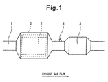
- Fig. 1 is a schematic view showing an embodiment of the exhaust purification system of an internal combustion engine according to the present invention.
- reference numeral 1 is an exhaust passage of the engine.
- the engine is a diesel engine or a direct fuel injection-type spark-ignition engine which performs lean combustion.
- the exhaust gas of such an engine includes a relatively large amount of NO x so that a silver-alumina-based catalyst device 2 for adsorbing NO x is arranged in the exhaust passage 1.
- a NO x reduction catalyst device 3 for reducing NO x is arranged downstream of the silver-alumina-based catalyst device 2.
- a reducing material supply device 4 is arranged between the silver-alumina-based catalyst device 2 and the NO x reduction catalyst device 3.
- An electric heater 5 for heating the silver-alumina-based catalyst device 2 is arranged around the silver-alumina-based catalyst device 2.
- the silver-alumina-based catalyst device 2 carries silver oxide by use of alumina as a carrier coat material, can adsorb NO 2 in the exhaust gas as silver nitrate, and releases the adsorbed NO 2 if a first set temperature (about 300 degrees C) is reached.
- a first set temperature about 300 degrees C
- the NO x reduction catalyst device 3 has been sufficiently activated and thus the released NO 2 can be purified by reduction at the NO x reduction catalyst device 3 by a reducing material supplied from the reducing material supply device 4.
- the silver-alumina-based catalyst device 2 is arranged upstream of the NO x reduction catalyst device 3, it is possible to sufficiently keep the NO 2 in the exhaust gas from released into the atmosphere before the NO x reduction catalyst device 3 is activated.
- the silver-alumina-based catalyst device 2 for example, comprises a honeycomb-shaped base material on which an alumina Al 2 O 3 carrier coat layer is formed and carrying silver oxide Ag 2 O on the alumina carrier coat layer in a ratio of silver 0.2mol to alumina 200g (for improving the heat resistance, lanthanum La may also be mixed in).
- alumina MI386 (La/Al 2 O 3 ) powder 1600g, a binder A520 710.4g, and water 3600g are stirred by an atriter for 20 minutes, then the mixture is coated on the base material at 200g/liter per unit volume. Next, this is fired in the atmosphere at 250 degrees C for 30 minutes, then fired at 500 degrees C for 1 hour to form an alumina carrier coat layer on the base material.
- ion exchanged water is added to silver nitrate 236.2g to make it dissolve to give a volume of 1700cc to thereby prepare a silver nitrate aqueous solution with an Ag concentration of 0.82mol/liter.
- alumina carrier coat layer is immersed in such a silver nitrate aqueous solution for 30 minutes to cause Ag to be carried at 0.2mol/liter per unit volume by absorption.
- a blower type dryer is operated to dry the catalyst for 20 minutes, the catalyst is fired in the atmosphere at 550 degrees C for 3 hours, then the catalyst is fired at 500 degrees C for 3 hours while running nitrogen containing 5% of hydrogen at a rate of 7 liters a minute.
- the silver oxide Ag 2 O is exposed from the alumina Al 2 O 3 carrier coat layer. After the NO in the exhaust gas is oxidized to NO 2 , this can be held well as silver nitrate AgNO 3 .
- the NO x reduction catalyst device 3 can be made a three-way catalyst device.
- the reducing material supply device 4 as the reducing material, for example, the fuel is supplied.
- the air-fuel ratio of the exhaust gas in the three-way catalyst device is made rich to purify the NO x by reduction.
- the NO x reduction catalyst device 3 can be made a selective reduction type NO x catalyst device which uses ammonia NH 3 to selectively purify NO x by reduction.
- the reducing material supply device 4 supplies urea as a reducing material, for example.
- the urea is hydrolyzed to generate ammonia to purify the NO x by reduction.
- the NO x reduction catalyst device 3 is comprised of an upstream side oxidation catalyst device (carrying platinum Pt, silver Ag, or copper Cu, etc.) which can partially oxidize the hydrocarbons in the exhaust gas and a downstream side catalyst device (carrying platinum Pt or rhodium Rh) which purify nitrogen-containing hydrocarbon compounds (amine compounds, isocyanate compounds, and nitroso compounds) generated in the oxidation catalyst device from the partially oxidized hydrocarbons and NO x in the exhaust gas, hydrocarbons (fuel) are supplied as a reducing material from the reducing material supply device 4 for purifying the NO x .
- an upstream side oxidation catalyst device carrier comprising platinum Pt, silver Ag, or copper Cu, etc.
- a downstream side catalyst device comprising platinum Pt or rhodium Rh
- the nitrogen-containing hydrocarbon compounds become easier to generate in the oxidation catalyst device and substantially all of the NO x in the exhaust gas can be purified.
- the silver-alumina-based catalyst device 2 the first set temperature (T1)
- the NO 2 in the exhaust gas which is adsorbed as silver nitrate AgNO 3 is released when the silver-alumina-based catalyst device 2 becomes the first set temperature (T1), and the released NO 2 can be purified by reduction by the downstream side NO x reduction catalyst device 3.
- the NO in the exhaust gas is also adsorbed at the silver-alumina-based catalyst device 2, but the NO is adsorbed at the silver-alumina-based catalyst device 2 as silver nitrite AgNO 2 .
- the NO which is adsorbed as silver nitrite ends up being released from the silver-alumina-based catalyst device 2 at a second set temperature (T2) (about 150 degrees C) which is lower than the first set temperature (T1).
- T2 second set temperature
- T1 first set temperature
- the downstream side NO x reduction catalyst device 3 is not sufficiently activated, and the NO which flows out from the silver-alumina-based catalyst device 2 ends up being released into the atmosphere without being purified by reduction at the NO x reduction catalyst device 3.
- an electronic control unit (not shown) operates the electric heater 5 in accordance with the flow of the first flow chart shown in Fig. 2 to carry out a heating control of the silver-alumina-based catalyst device 2.
- the flow of the first flow chart of Fig. 2 is started at the same time as engine startup.
- step 101 it is estimated that an amount of NO (a) exhausted from each cylinder is newly adsorbed in the silver-alumina-based catalyst device 2 as silver nitrite AgNO 2 per unit time (interval of execution of flow chart) on the basis of the current engine operating condition.
- an amount of NO (a) can be experimentally set in a map each engine operating condition and such a map can be used in the estimation at step 101.
- the amount of NO (a) estimated at step 101 is integrated to calculate a current amount of NO (A) adsorbed in the silver-alumina-based catalyst device 2.
- a current temperature (T) of the silver-alumina-based catalyst device 2 is estimated.
- a temperature sensor is arranged immediately downstream of the silver-alumina-based catalyst device 2 to measure a temperature of the exhaust gas flowing out from the silver-alumina-based catalyst device 2, and the measured temperature may be used as the current temperature (T) of the silver-alumina-based catalyst device 2.
- the current temperature (T) of the silver-alumina-based catalyst device 2 may be estimated on the basis of a temperature of the exhaust gas flowing into the silver-alumina-based catalyst device 2, which is estimated on the basis of the current engine operating condition.
- the temperature of the silver-alumina-based catalyst device 2 may be directly measured.
- step 104 it is determined if the current temperature (T) of the silver-alumina-based catalyst device 2 reaches the second set temperature (T2) (or a temperature slightly lower than the second set temperature).
- T2 the second set temperature
- a releasing rate (VL) of NO released from the silver-alumina-based catalyst device 2 at the second set temperature (T2) is estimated on the basis of the current amount of adsorbed NO (A), and a third temperature (T3) of the silver-alumina-based catalyst device 2 is set such that an oxidation rate (VO) of NO to NO 2 in the silver-alumina-based catalyst device 2 at the third temperature is equal to the releasing rate (VL).
- T2 second set temperature
- a quantity of heat (H) generated by the electric heater 5 which is needed to elevate from the second set temperature (T2) of the silver-alumina-based catalyst device 2 to the third set temperature (T3) is determined.
- the quantity of heat (H) determined at step 106 is generated by the electric heater 5, preferably instantaneously, and thus the silver-alumina-based catalyst device 2 is heated.
- the amount of NO (A) adsorbed in the silver-alumina-based catalyst device 2 is reset to 0 and the routine is finished.
- the temperature of the silver-alumina-based catalyst device 2 is equal to or higher than the third set temperature (T3), NO in the exhaust gas is oxidized to NO 2 and is adsorbed in the silver-alumina-based catalyst device so that the amount of NO (a) estimated at step 101 is 0 and the amount of NO (A) adsorbed in the silver-alumina-based catalyst device 2 is maintained to 0 during the engine operation.
- the amount of adsorbed NO (A) may be forcibly maintained to 0 for the next engine startup.
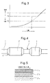
- Fig. 3 is a time chart showing a change in the temperature of the silver-alumina-based catalyst device 2 according to the heating control of the flow chart of Fig. 2 .
- the temperature (T) of the silver-alumina-based catalyst device 2 from the engine startup gradually becomes higher according to the elapsed time and reaches the second temperature (T2) at a time (t1).
- T2 the second temperature
- T1 the releasing of NO adsorbed as silver nitrite AgNO 2 from the engine startup to the time (t1) is begun.
- the temperature (T) of the silver-alumina-based catalyst device 2 merely increases gradually as shown by a dotted line and the oxidation ability of the silver-alumina-based catalyst device 2 also merely increases gradually. Therefore, NO released from the silver-alumina-based catalyst device 2 almost flows out from the silver-alumina-based catalyst device 2 without the oxidation to NO 2 and is emitted into the atmosphere as it is because the NO x reduction catalyst device 3 arranged downstream thereof is not sufficiently activated.
- the temperature (T) of the silver-alumina-based catalyst device 2 is instantaneously increased to the third set temperature (T3) at the time (t1) as shown by a solid line.
- the third set temperature (T3) is set such that the NO oxidation rate (VO) of the silver-alumina-based catalyst device 2 at the third set temperature (T3) is equal to the NO releasing rate (VL) when the temperature of the silver-alumina-based catalyst device 2 is the second set temperature (T2) so that the most NO released from the silver-alumina-based catalyst device 2 after the temperature thereof becomes the second set temperature (T2) can be oxidized to NO 2 in the silver-alumina-based catalyst device 2 of which temperature is made the third set temperature (T3) and can be adsorbed again therein.
- an amount of NO flowing out from the silver-alumina-based catalyst device can be sufficiently decreased.
- the third set temperature (T3) is set such that the NO oxidation rate (VO) of the silver-alumina-based catalyst device 2 at the third set temperature (T3) is larger than the NO releasing rate (VL) when the temperature of the silver-alumina-based catalyst device 2 is the second set temperature (T2), the NO released from the silver-alumina-based catalyst device 2 after the temperature thereof becomes the second set temperature (T2) can be almost oxidized to NO 2 and can be almost adsorbed again. Therefore, NO does not almost flow out from the silver-alumina-based catalyst device.
- the temperature elevation rate of the silver-alumina-based catalyst device 2 from the second set temperature (T2) to the third set temperature (T3) is surely increased by the heating of the silver-alumina-based catalyst device 2.
- a period while the temperature of the silver-alumina-based catalyst device 2 is elevated from the second set temperature (t2) to the third set temperature (T3) is preferably shortened as far as possible and is desired to be instantaneous as shown in Fig. 3 .
- the third set temperature (T3) is not lower than the first set temperature (T1) at which the silver-alumina-based catalyst device 2 releases NO 2 , NO can be oxidized to NO 2 therein but NO 2 cannot be adsorbed therein. Thus, if NO 2 flows out from the silver-alumina-based catalyst device 2, NO 2 is emitted into the atmosphere as it is because the NO x reduction catalyst device 3 arranged downstream thereof is not sufficiently activated.
- the third set temperature (T3) is made between the first set temperature (T1) and the second set temperature (T2) and the silver-alumina-based catalyst device 2 is maintained at the third set temperature (T3) as it is after the temperature thereof is elevated to the third set temperature (T3) at the time (t1). If the temperature of the exhaust gas exhausted from the cylinders becomes higher than the third set temperature (T3), the temperature of the silver-alumina-based catalyst device is gradually increased to the first set temperature (T1) with the temperature of the NO x reduction catalyst device 3. Therefore, when the temperature of the silver-alumina-based catalyst device 2 elevates to the first set temperature (T1) and NO 2 is released from the silver-alumina-based catalyst device 2, the NO x reduction catalyst device 3 arranged downstream thereof has been sufficiently activated.
- the temperature of the silver-alumina-based catalyst device 2 is maintained at the third set temperature (T3).
- the electric heater 5 continues heating the silver-alumina-based catalyst device 2.
- Fig. 4 is a schematic view showing another embodiment of the exhaust purification system of an internal combustion engine according to the present invention.
- the heating means of the silver-alumina-based catalyst device 2' is not the electric heater 5 but a flame burner 6. Accordingly, at step 106 of the flow chart shown in Fig. 2 , a quantity of heat (a strength of the flame) generated by the flame burner 6 which is necessary to elevate from the second set temperature (T2) of the silver-alumina-based catalyst device 2' to the third set temperature (T3) is determined.
- the silver-alumina-based catalyst device 2' is heated by the flame burner 6.
- the heating by the flame burner 7 is carried out.
- the silver-alumina-based catalyst device 2' of Fig. 4 may have a lower layer 2'b which carries silver oxide by alumina as a carrier coat material on a ceramic base 2'a and an upper layer 2'c formed from zeolite or the like.
- the upper layer 2'c functions as a HC adsorption layer for adsorbing HC in the exhaust gas. Accordingly, the upper layer 2'c continues adsorbing HC in the exhaust gas to an upper limit from the engine startup.
- T2 the second set temperature
- a part of HC adsorbed in the upper layer 2'c is released from the upper layer 2'c, ignited, and burned. Thereafter, by the burning heat, the remainder of HC adsorbed in the upper layer 2'c is instantaneously released, ignited, and burned. Accordingly, the temperature of the silver-alumina-based catalyst device 2' can be instantaneously elevated.
- the silver-alumina-based catalyst device 2' is heated to increase the temperature elevation rate thereof so that at least part of NO flowing out from the silver-alumina-based catalyst device 2 as it is can be oxidized to NO 2 in the silver-alumina-based catalyst device 2 and can be adsorbed therein.
- an amount of NO flowing out from the silver-alumina-based catalyst device 2 after the temperature thereof becomes the second set temperature (T2) can be decreased.
- the upper limit of HC adsorption in the upper layer varies according to the material and the volume of the upper layer 2'c, and it is preferable that the upper limit is set such that even if all thereof burns, the temperature of the silver-alumina-based catalyst device 2' is not elevated from the second set temperature (T2) to the first set temperature (T1).
- the reducing material supply device 4 may be arranged upstream of the silver-alumina-based catalyst device 2.
- the fuel injector for injecting fuel into the cylinder can be used as the reducing material supply device and the fuel injector may inject fuel into the cylinder, for example, in the expansion stroke.
Landscapes
- Engineering & Computer Science (AREA)
- Chemical & Material Sciences (AREA)
- Combustion & Propulsion (AREA)
- Chemical Kinetics & Catalysis (AREA)
- Mechanical Engineering (AREA)
- General Engineering & Computer Science (AREA)
- Health & Medical Sciences (AREA)
- Toxicology (AREA)
- Biomedical Technology (AREA)
- Environmental & Geological Engineering (AREA)
- Analytical Chemistry (AREA)
- General Chemical & Material Sciences (AREA)
- Oil, Petroleum & Natural Gas (AREA)
- Exhaust Gas Treatment By Means Of Catalyst (AREA)
- Catalysts (AREA)
- Exhaust Gas After Treatment (AREA)
Abstract
Description
- The present invention relates to an exhaust purification system of an internal combustion engine.
- A known catalyst device carries silver oxide by use of alumina as a carrier coat material (for example, refer to Japanese Patent No.
2801423 - The above mentioned silver-alumina-based catalyst device does not only adsorb NO2 in the exhaust gas but also NO in the exhaust gas. However, the adsorbed NO is released at a temperature lower than the set temperature. At this time, the NOx catalyst device arranged downstream thereof has not been activated. Therefore, the NO which flows out from the silver-alumina-based catalyst device is not purified by reduction in the NOx catalyst device, and is emitted into the atmosphere.
- Accordingly, an object of the present invention is to provide an exhaust purification system of an internal combustion engine, comprising a silver-alumina-based catalyst device, which can decrease an amount of NO which flows out from the silver-alumina-based catalyst device when the temperature thereof is lower than a set temperature at which NO2 is released.
- An exhaust purification system of an internal combustion engine as set forth in
claim 1 of the present invention is provided, characterized in that the system comprises a silver-alumina-based catalyst device arranged in the engine exhaust system, when a temperature of the silver-alumina-based catalyst device becomes a second set temperature lower than a first set temperature at which the silver-alumina-based catalyst device releases NO2, and releases NO, the silver-alumina-based catalyst device is heated such that a temperature elevation rate thereof is increased to make the temperature of the silver-alumina-based catalyst device be a third set temperature between the first set temperature and the second set temperature. - An exhaust purification system of an internal combustion engine as set forth in
claim 2 of the present invention is provided as the exhaust purification system of an internal combustion engine as set forth inclaim 1 characterized in that when the temperature of the silver-alumina-based catalyst devices becomes the second set temperature, the silver-alumina-based catalyst device is heated by a flame burner or an electric heater. - An exhaust purification system of an internal combustion engine as set forth in
claim 3 of the present invention is provided as the exhaust purification system of an internal combustion engine as set forth inclaim 1 characterized in that the silver-alumina-based catalyst device comprises a HC adsorption layer, and when the temperature of the silver-alumina-based catalyst devices becomes the second set temperature, the HC adsorbed in the HC adsorption layer is ignited and burned so that the silver-alumina-based catalyst device is heated. - An exhaust purification system of an internal combustion engine as set forth in
claim 4 of the present invention is provided as the exhaust purification system of an internal combustion engine as set forth in any one of claims 1-3 characterized in that the third set temperature is set such that a NO oxidation rate of the silver-alumina-based catalyst device at the third set temperature is equal to or larger than a NO releasing rate of the silver-alumina-based catalyst device at the second set temperature. - According to the exhaust purification system of an internal combustion engine as set forth in
claim 1 of the present invention, when a temperature of the silver-alumina-based catalyst device becomes a second set temperature lower than a first set temperature at which the silver-alumina-based catalyst device releases NO2, and releases NO, the silver-alumina-based catalyst device is heated such that a temperature elevation rate thereof is increased to make the temperature of the silver-alumina-based catalyst device be a third set temperature between the first set temperature and the second set temperature. Therefore, the NO released when the temperature of the silver-alumina-based catalyst device becomes the second set temperature is oxidized to NO2 to be adsorbed in the silver-alumina-based catalyst device again because a temperature elevation rate thereof is increased by heating simultaneously with the NO releasing and an oxidation ability of the silver-alumina-based catalyst device is increased. Thus, when the temperature of the silver-alumina-based catalyst device is lower than the first set temperature at which NO2 is released, an amount of NO which flows out from the silver-alumina-based catalyst device after the temperature thereof becomes the second set temperature can be decreased. - According to the exhaust purification system of the internal combustion engine as set set forth in
claim 2 of the present invention, in the exhaust purification system of an internal combustion engine as set set forth inclaim 1, when the temperature of the silver-alumina-based catalyst devices becomes the second set temperature, the silver-alumina-based catalyst device can be easily heated by a flame burner or an electric heater. - According to the exhaust purification system of the internal combustion engine as set forth in
claim 3 of the present invention, in the exhaust purification system of an internal combustion engine as set forth inclaim 1, the silver-alumina-based catalyst device comprises a HC adsorption layer, and when the temperature of the silver-alumina-based catalyst devices becomes the second set temperature, the HC adsorbed in the HC adsorption layer is ignited and burned so that the silver-alumina-based catalyst device can be easily heated. - According to the exhaust purification system of the internal combustion engine as set forth in
claim 4 of the present invention, in the exhaust purification system of an internal combustion engine as set forth in any one of claims 1-3, the third set temperature is set such that a NO oxidation rate of the silver-alumina-based catalyst device at the third set temperature is equal to or larger than a NO releasing rate of the silver-alumina-based catalyst device at the second set temperature. Therefore, most of the NO released when the temperature of the silver-alumina-based catalyst device becomes the second set temperature can be oxidized to NO2 to be adsorbed in the silver-alumina-based catalyst device again and thus an amount of NO which flows out from the silver-alumina-based catalyst device can be sufficiently decreased. -
-
Fig. 1 is a schematic view showing an embodiment of the exhaust purification system of an internal combustion engine according to the present invention. -
Fig. 2 is a flow-chart showing a heating control of the silver-alumina-based catalyst device carried out in the exhaust purification system according to the present invention. -
Fig. 3 is a time-chart showing a change in the temperature of the silver-alumina-based catalyst device according to the heating control ofFig. 2 . -
Fig. 4 is a schematic view showing another embodiment of the exhaust purification system of an internal combustion engine according to the present invention. -
Fig. 5 is an enlarged partial sectional view of the silver-alumina-based catalyst device. -
Fig. 1 is a schematic view showing an embodiment of the exhaust purification system of an internal combustion engine according to the present invention. InFig. 1 ,reference numeral 1 is an exhaust passage of the engine. The engine is a diesel engine or a direct fuel injection-type spark-ignition engine which performs lean combustion. The exhaust gas of such an engine includes a relatively large amount of NOx so that a silver-alumina-basedcatalyst device 2 for adsorbing NOx is arranged in theexhaust passage 1. A NOxreduction catalyst device 3 for reducing NOx is arranged downstream of the silver-alumina-basedcatalyst device 2. A reducingmaterial supply device 4 is arranged between the silver-alumina-basedcatalyst device 2 and the NOxreduction catalyst device 3. An electric heater 5 for heating the silver-alumina-basedcatalyst device 2 is arranged around the silver-alumina-basedcatalyst device 2. - The silver-alumina-based
catalyst device 2 carries silver oxide by use of alumina as a carrier coat material, can adsorb NO2 in the exhaust gas as silver nitrate, and releases the adsorbed NO2 if a first set temperature (about 300 degrees C) is reached. At this time, the NOxreduction catalyst device 3 has been sufficiently activated and thus the released NO2 can be purified by reduction at the NOxreduction catalyst device 3 by a reducing material supplied from the reducingmaterial supply device 4. Thus, if the silver-alumina-basedcatalyst device 2 is arranged upstream of the NOxreduction catalyst device 3, it is possible to sufficiently keep the NO2 in the exhaust gas from released into the atmosphere before the NOxreduction catalyst device 3 is activated. - The silver-alumina-based
catalyst device 2, for example, comprises a honeycomb-shaped base material on which an alumina Al2O3 carrier coat layer is formed and carrying silver oxide Ag2O on the alumina carrier coat layer in a ratio of silver 0.2mol to alumina 200g (for improving the heat resistance, lanthanum La may also be mixed in). - As the method of preparation of such a catalyst, for example, alumina MI386 (La/Al2O3) powder 1600g, a binder A520 710.4g, and water 3600g are stirred by an atriter for 20 minutes, then the mixture is coated on the base material at 200g/liter per unit volume. Next, this is fired in the atmosphere at 250 degrees C for 30 minutes, then fired at 500 degrees C for 1 hour to form an alumina carrier coat layer on the base material.
- On the other hand, ion exchanged water is added to silver nitrate 236.2g to make it dissolve to give a volume of 1700cc to thereby prepare a silver nitrate aqueous solution with an Ag concentration of 0.82mol/liter.
- The above-mentioned alumina carrier coat layer is immersed in such a silver nitrate aqueous solution for 30 minutes to cause Ag to be carried at 0.2mol/liter per unit volume by absorption. Next, a blower type dryer is operated to dry the catalyst for 20 minutes, the catalyst is fired in the atmosphere at 550 degrees C for 3 hours, then the catalyst is fired at 500 degrees C for 3 hours while running nitrogen containing 5% of hydrogen at a rate of 7 liters a minute.
- In a catalyst which is prepared in this way, the silver oxide Ag2O is exposed from the alumina Al2O3 carrier coat layer. After the NO in the exhaust gas is oxidized to NO2, this can be held well as silver nitrate AgNO3.
- The NOx
reduction catalyst device 3 can be made a three-way catalyst device. In this case, from the reducingmaterial supply device 4, as the reducing material, for example, the fuel is supplied. The air-fuel ratio of the exhaust gas in the three-way catalyst device is made rich to purify the NOx by reduction. - Further, the NOx
reduction catalyst device 3 can be made a selective reduction type NOx catalyst device which uses ammonia NH3 to selectively purify NOx by reduction. In this case, the reducingmaterial supply device 4 supplies urea as a reducing material, for example. At the selective reduction type NOx catalyst device, the urea is hydrolyzed to generate ammonia to purify the NOx by reduction. - Further, if the NOx
reduction catalyst device 3 is comprised of an upstream side oxidation catalyst device (carrying platinum Pt, silver Ag, or copper Cu, etc.) which can partially oxidize the hydrocarbons in the exhaust gas and a downstream side catalyst device (carrying platinum Pt or rhodium Rh) which purify nitrogen-containing hydrocarbon compounds (amine compounds, isocyanate compounds, and nitroso compounds) generated in the oxidation catalyst device from the partially oxidized hydrocarbons and NOx in the exhaust gas, hydrocarbons (fuel) are supplied as a reducing material from the reducingmaterial supply device 4 for purifying the NOx. In particular, if the supplied hydrocarbons are used to the air-fuel ratio of the exhaust gas a 15.5 or less lean air-fuel ratio, the nitrogen-containing hydrocarbon compounds become easier to generate in the oxidation catalyst device and substantially all of the NOx in the exhaust gas can be purified. - As explained above, until the silver-alumina-based
catalyst device 2 the first set temperature (T1), the NO2 in the exhaust gas which is adsorbed as silver nitrate AgNO3 is released when the silver-alumina-basedcatalyst device 2 becomes the first set temperature (T1), and the released NO2 can be purified by reduction by the downstream side NOxreduction catalyst device 3. - On the other hand, the NO in the exhaust gas is also adsorbed at the silver-alumina-based
catalyst device 2, but the NO is adsorbed at the silver-alumina-basedcatalyst device 2 as silver nitrite AgNO2. The NO which is adsorbed as silver nitrite ends up being released from the silver-alumina-basedcatalyst device 2 at a second set temperature (T2) (about 150 degrees C) which is lower than the first set temperature (T1). At this time, the downstream side NOxreduction catalyst device 3 is not sufficiently activated, and the NO which flows out from the silver-alumina-basedcatalyst device 2 ends up being released into the atmosphere without being purified by reduction at the NOxreduction catalyst device 3. - Due to this, at the second set temperature (T2) which is lower than the first set temperature (T1) at which NO2 is released, it is desirable to reduce the amount of NO which flows out from the silver-alumina-based catalyst device.
- To realize this, in the exhaust purification system of an internal combustion engine of the present embodiment, an electronic control unit (not shown) operates the electric heater 5 in accordance with the flow of the first flow chart shown in
Fig. 2 to carry out a heating control of the silver-alumina-basedcatalyst device 2. The flow of the first flow chart ofFig. 2 is started at the same time as engine startup. - First, at
step 101, it is estimated that an amount of NO (a) exhausted from each cylinder is newly adsorbed in the silver-alumina-basedcatalyst device 2 as silver nitrite AgNO2 per unit time (interval of execution of flow chart) on the basis of the current engine operating condition. For example, such an amount of NO (a) can be experimentally set in a map each engine operating condition and such a map can be used in the estimation atstep 101. - Next, at
step 102, the amount of NO (a) estimated atstep 101 is integrated to calculate a current amount of NO (A) adsorbed in the silver-alumina-basedcatalyst device 2. Atstep 103, a current temperature (T) of the silver-alumina-basedcatalyst device 2 is estimated. For example, a temperature sensor is arranged immediately downstream of the silver-alumina-basedcatalyst device 2 to measure a temperature of the exhaust gas flowing out from the silver-alumina-basedcatalyst device 2, and the measured temperature may be used as the current temperature (T) of the silver-alumina-basedcatalyst device 2. The current temperature (T) of the silver-alumina-basedcatalyst device 2 may be estimated on the basis of a temperature of the exhaust gas flowing into the silver-alumina-basedcatalyst device 2, which is estimated on the basis of the current engine operating condition. The temperature of the silver-alumina-basedcatalyst device 2 may be directly measured. - Next, at
step 104, it is determined if the current temperature (T) of the silver-alumina-basedcatalyst device 2 reaches the second set temperature (T2) (or a temperature slightly lower than the second set temperature). When the result atstep 104 is negative, the routine is finished. - On the other hand, when the result at
step 104 is positive, atstep 105, a releasing rate (VL) of NO released from the silver-alumina-basedcatalyst device 2 at the second set temperature (T2) is estimated on the basis of the current amount of adsorbed NO (A), and a third temperature (T3) of the silver-alumina-basedcatalyst device 2 is set such that an oxidation rate (VO) of NO to NO2 in the silver-alumina-basedcatalyst device 2 at the third temperature is equal to the releasing rate (VL). The larger the amount of NO (A) adsorbed in the silver-alumina-basedcatalyst device 2 at this time is, the larger the releasing rate (VL) of NO released from the silver-alumina-basedcatalyst device 2 at the second set temperature (T2) (about 150 degrees C), i.e., an amount of NO released per unit time is. The higher the temperature of the silver-alumina-based catalyst device is, the larger the oxidation rate of the silver-alumina-basedcatalyst device 2, i.e., an amount of NO oxidized per unit time is. - Next, at
step 106, a quantity of heat (H) generated by the electric heater 5 which is needed to elevate from the second set temperature (T2) of the silver-alumina-basedcatalyst device 2 to the third set temperature (T3) is determined. Atstep 107, the quantity of heat (H) determined atstep 106 is generated by the electric heater 5, preferably instantaneously, and thus the silver-alumina-basedcatalyst device 2 is heated. Next, atstep 108, the amount of NO (A) adsorbed in the silver-alumina-basedcatalyst device 2 is reset to 0 and the routine is finished. When the temperature of the silver-alumina-basedcatalyst device 2 is equal to or higher than the third set temperature (T3), NO in the exhaust gas is oxidized to NO2 and is adsorbed in the silver-alumina-based catalyst device so that the amount of NO (a) estimated atstep 101 is 0 and the amount of NO (A) adsorbed in the silver-alumina-basedcatalyst device 2 is maintained to 0 during the engine operation. After the amount of adsorbed NO (A) is reset to 0 atstep 108, the amount of adsorbed NO (A) may be forcibly maintained to 0 for the next engine startup. -
Fig. 3 is a time chart showing a change in the temperature of the silver-alumina-basedcatalyst device 2 according to the heating control of the flow chart ofFig. 2 . The temperature (T) of the silver-alumina-basedcatalyst device 2 from the engine startup gradually becomes higher according to the elapsed time and reaches the second temperature (T2) at a time (t1). At this time, the releasing of NO adsorbed as silver nitrite AgNO2 from the engine startup to the time (t1) is begun. - When the heating control is not carried out, the temperature (T) of the silver-alumina-based
catalyst device 2 merely increases gradually as shown by a dotted line and the oxidation ability of the silver-alumina-basedcatalyst device 2 also merely increases gradually. Therefore, NO released from the silver-alumina-basedcatalyst device 2 almost flows out from the silver-alumina-basedcatalyst device 2 without the oxidation to NO2 and is emitted into the atmosphere as it is because the NOxreduction catalyst device 3 arranged downstream thereof is not sufficiently activated. - However, by the heating control of the flow chart in
Fig. 2 , the temperature (T) of the silver-alumina-basedcatalyst device 2 is instantaneously increased to the third set temperature (T3) at the time (t1) as shown by a solid line. The third set temperature (T3) is set such that the NO oxidation rate (VO) of the silver-alumina-basedcatalyst device 2 at the third set temperature (T3) is equal to the NO releasing rate (VL) when the temperature of the silver-alumina-basedcatalyst device 2 is the second set temperature (T2) so that the most NO released from the silver-alumina-basedcatalyst device 2 after the temperature thereof becomes the second set temperature (T2) can be oxidized to NO2 in the silver-alumina-basedcatalyst device 2 of which temperature is made the third set temperature (T3) and can be adsorbed again therein. Thus, an amount of NO flowing out from the silver-alumina-based catalyst device can be sufficiently decreased. - If the third set temperature (T3) is set such that the NO oxidation rate (VO) of the silver-alumina-based
catalyst device 2 at the third set temperature (T3) is larger than the NO releasing rate (VL) when the temperature of the silver-alumina-basedcatalyst device 2 is the second set temperature (T2), the NO released from the silver-alumina-basedcatalyst device 2 after the temperature thereof becomes the second set temperature (T2) can be almost oxidized to NO2 and can be almost adsorbed again. Therefore, NO does not almost flow out from the silver-alumina-based catalyst device. - The temperature elevation rate of the silver-alumina-based
catalyst device 2 from the second set temperature (T2) to the third set temperature (T3) is surely increased by the heating of the silver-alumina-basedcatalyst device 2. A period while the temperature of the silver-alumina-basedcatalyst device 2 is elevated from the second set temperature (t2) to the third set temperature (T3) is preferably shortened as far as possible and is desired to be instantaneous as shown inFig. 3 . - However, at the time (t1) (when the temperature of the silver-alumina-based
catalyst device 2 becomes the second set temperature (T2)), if the silver-alumina-basedcatalyst device 2 is heated to increase the temperature elevation rate thereof, the oxidation ability of the silver-alumina-basedcatalyst device 2 can be surely increased. Therefore, at least part of NO flowing out from the silver-alumina-basedcatalyst device 2 as it is can be oxidized to NO2 in the silver-alumina-basedcatalyst device 2 and can be adsorbed therein. Thus, an amount of NO flowing out from the silver-alumina-basedcatalyst device 2 after the temperature thereof becomes the second set temperature (T2) can be decreased. - If the third set temperature (T3) is not lower than the first set temperature (T1) at which the silver-alumina-based
catalyst device 2 releases NO2, NO can be oxidized to NO2 therein but NO2 cannot be adsorbed therein. Thus, if NO2 flows out from the silver-alumina-basedcatalyst device 2, NO2 is emitted into the atmosphere as it is because the NOxreduction catalyst device 3 arranged downstream thereof is not sufficiently activated. - In the present embodiment, the third set temperature (T3) is made between the first set temperature (T1) and the second set temperature (T2) and the silver-alumina-based
catalyst device 2 is maintained at the third set temperature (T3) as it is after the temperature thereof is elevated to the third set temperature (T3) at the time (t1). If the temperature of the exhaust gas exhausted from the cylinders becomes higher than the third set temperature (T3), the temperature of the silver-alumina-based catalyst device is gradually increased to the first set temperature (T1) with the temperature of the NOxreduction catalyst device 3. Therefore, when the temperature of the silver-alumina-basedcatalyst device 2 elevates to the first set temperature (T1) and NO2 is released from the silver-alumina-basedcatalyst device 2, the NOxreduction catalyst device 3 arranged downstream thereof has been sufficiently activated. - Thus, while NO is released from the silver-alumina-based
catalyst device 2 after the time (t1), it is preferable that the temperature of the silver-alumina-basedcatalyst device 2 is maintained at the third set temperature (T3). For this purpose, after the temperature of the silver-alumina-basedcatalyst device 2 is elevated to the third set temperature (T3), it is preferable that the electric heater 5 continues heating the silver-alumina-basedcatalyst device 2. -
Fig. 4 is a schematic view showing another embodiment of the exhaust purification system of an internal combustion engine according to the present invention. A difference between the present embodiment and the embodiment shown inFig. 1 is that the heating means of the silver-alumina-based catalyst device 2' is not the electric heater 5 but aflame burner 6. Accordingly, atstep 106 of the flow chart shown inFig. 2 , a quantity of heat (a strength of the flame) generated by theflame burner 6 which is necessary to elevate from the second set temperature (T2) of the silver-alumina-based catalyst device 2' to the third set temperature (T3) is determined. Atstep 107, the silver-alumina-based catalyst device 2' is heated by theflame burner 6. To maintain the temperature of the silver-alumina-based catalyst device 2' at the third set temperature (T3), the heating by the flame burner 7 is carried out. - The silver-alumina-based catalyst device 2' of
Fig. 4 may have a lower layer 2'b which carries silver oxide by alumina as a carrier coat material on a ceramic base 2'a and an upper layer 2'c formed from zeolite or the like. In this case, the upper layer 2'c functions as a HC adsorption layer for adsorbing HC in the exhaust gas. Accordingly, the upper layer 2'c continues adsorbing HC in the exhaust gas to an upper limit from the engine startup. Once the temperature of the silver-alumina-based catalyst device 2' becomes the second set temperature (T2), theflame burner 6 projects the flame into the silver-alumina-based catalyst device 2' without the control of a quantity of generated heat. - Therefore, a part of HC adsorbed in the upper layer 2'c is released from the upper layer 2'c, ignited, and burned. Thereafter, by the burning heat, the remainder of HC adsorbed in the upper layer 2'c is instantaneously released, ignited, and burned. Accordingly, the temperature of the silver-alumina-based catalyst device 2' can be instantaneously elevated.
- Thus, at the time (t1) (when the temperature of the silver-alumina-based catalyst device 2' becomes the second set temperature (T2)), the silver-alumina-based catalyst device 2' is heated to increase the temperature elevation rate thereof so that at least part of NO flowing out from the silver-alumina-based
catalyst device 2 as it is can be oxidized to NO2 in the silver-alumina-basedcatalyst device 2 and can be adsorbed therein. Thus, an amount of NO flowing out from the silver-alumina-basedcatalyst device 2 after the temperature thereof becomes the second set temperature (T2) can be decreased. - The upper limit of HC adsorption in the upper layer varies according to the material and the volume of the upper layer 2'c, and it is preferable that the upper limit is set such that even if all thereof burns, the temperature of the silver-alumina-based catalyst device 2' is not elevated from the second set temperature (T2) to the first set temperature (T1).
- The reducing
material supply device 4 may be arranged upstream of the silver-alumina-basedcatalyst device 2. In the case that fuel is used as the reducing material, the fuel injector for injecting fuel into the cylinder can be used as the reducing material supply device and the fuel injector may inject fuel into the cylinder, for example, in the expansion stroke. -
- 1:
- exhaust passage
- 2, 2':
- silver-alumina-based catalyst device
- 3:
- NOx catalyst device
- 4:
- reducing material supply device
- 5:
- electric heater
- 6:
- flame burner
Claims (4)
- An exhaust purification system of an internal combustion engine, characterized in that the system comprises a silver-alumina-based catalyst device arranged in the engine exhaust system, when a temperature of said silver-alumina-based catalyst device becomes a second set temperature lower than a first set temperature at which said silver-alumina-based catalyst device releases NO2, and releases NO, said silver-alumina-based catalyst device is heated such that a temperature elevation rate thereof is increased to make the temperature of said silver-alumina-based catalyst device be a third set temperature between said first set temperature and said second set temperature.
- An exhaust purification system of an internal combustion engine according to claim 1, characterized in that when the temperature of said silver-alumina-based catalyst devices becomes said second set temperature, said silver-alumina-based catalyst device is heated by a flame burner or an electric heater.
- An exhaust purification system of an internal combustion engine according to claim 1, characterized in that said silver-alumina-based catalyst device comprises a HC adsorption layer, and when the temperature of said silver-alumina-based catalyst devices becomes said second set temperature, the HC adsorbed in said HC adsorption layer is ignited and burnt so that said silver-alumina-based catalyst device is heated.
- An exhaust purification system of an internal combustion engine according to any one of claims 1-3, characterized in that said third set temperature is set such that a NO oxidation rate of said silver-alumina-based catalyst device at said third set temperature is equal to or larger than a NO releasing rate of said silver-alumina-based catalyst device at said second set temperature.
Applications Claiming Priority (1)
| Application Number | Priority Date | Filing Date | Title |
|---|---|---|---|
| PCT/JP2011/053586 WO2012111163A1 (en) | 2011-02-14 | 2011-02-14 | Exhaust conversion apparatus for internal combustion engine |
Publications (2)
| Publication Number | Publication Date |
|---|---|
| EP2676719A1 true EP2676719A1 (en) | 2013-12-25 |
| EP2676719A4 EP2676719A4 (en) | 2015-01-14 |
Family
ID=46672122
Family Applications (1)
| Application Number | Title | Priority Date | Filing Date |
|---|---|---|---|
| EP11824279.1A Withdrawn EP2676719A4 (en) | 2011-02-14 | 2011-02-14 | EXHAUST GAS CONVERTING APPARATUS FOR INTERNAL COMBUSTION ENGINE |
Country Status (5)
| Country | Link |
|---|---|
| US (1) | US8834802B2 (en) |
| EP (1) | EP2676719A4 (en) |
| JP (1) | JP5293837B2 (en) |
| CN (1) | CN103338843B (en) |
| WO (1) | WO2012111163A1 (en) |
Families Citing this family (1)
| Publication number | Priority date | Publication date | Assignee | Title |
|---|---|---|---|---|
| US9597635B2 (en) * | 2014-12-04 | 2017-03-21 | GM Global Technology Operations LLC | Zeolite promoted silver based catalyst for NOx storage |
Family Cites Families (9)
| Publication number | Priority date | Publication date | Assignee | Title |
|---|---|---|---|---|
| JP2801423B2 (en) | 1991-03-08 | 1998-09-21 | 住友金属鉱山 株式会社 | Nitrogen oxide purification catalyst |
| JP2783074B2 (en) | 1991-10-29 | 1998-08-06 | トヨタ自動車株式会社 | Exhaust gas purification device for internal combustion engine |
| JP3417702B2 (en) * | 1994-12-28 | 2003-06-16 | エヌ・イーケムキャット株式会社 | Nitrogen oxide storage composition and exhaust gas purification method |
| JP2004211565A (en) * | 2002-12-27 | 2004-07-29 | Honda Motor Co Ltd | Exhaust gas purification system and exhaust gas purification method |
| JP2004305841A (en) * | 2003-04-03 | 2004-11-04 | Honda Motor Co Ltd | NOx purification system |
| US8173574B2 (en) * | 2006-09-20 | 2012-05-08 | Basf Corporation | Catalysts to reduce NOx in an exhaust gas stream and methods of preparation |
| JP5141063B2 (en) | 2007-03-26 | 2013-02-13 | トヨタ自動車株式会社 | Exhaust gas purification device |
| JP2008240569A (en) | 2007-03-26 | 2008-10-09 | Toyota Motor Corp | Ignition timing control device for internal combustion engine |
| JP4769243B2 (en) | 2007-11-06 | 2011-09-07 | 本田技研工業株式会社 | Nitrogen oxide adsorption removal method |
-
2011
- 2011-02-14 CN CN201180003116.5A patent/CN103338843B/en not_active Expired - Fee Related
- 2011-02-14 EP EP11824279.1A patent/EP2676719A4/en not_active Withdrawn
- 2011-02-14 JP JP2011543027A patent/JP5293837B2/en not_active Expired - Fee Related
- 2011-02-14 WO PCT/JP2011/053586 patent/WO2012111163A1/en not_active Ceased
- 2011-02-14 US US13/389,486 patent/US8834802B2/en not_active Expired - Fee Related
Also Published As
| Publication number | Publication date |
|---|---|
| WO2012111163A1 (en) | 2012-08-23 |
| US8834802B2 (en) | 2014-09-16 |
| CN103338843B (en) | 2016-01-20 |
| US20130315791A1 (en) | 2013-11-28 |
| CN103338843A (en) | 2013-10-02 |
| EP2676719A4 (en) | 2015-01-14 |
| JPWO2012111163A1 (en) | 2014-07-03 |
| JP5293837B2 (en) | 2013-09-18 |
Similar Documents
| Publication | Publication Date | Title |
|---|---|---|
| US7207169B2 (en) | System and method for purifying an exhaust gas | |
| CN101573514A (en) | Exhaust gas purification device for internal combustion engine | |
| EP2676718B1 (en) | Exhaust conversion apparatus for internal combustion engine | |
| US8834802B2 (en) | Exhaust purification system of internal combustion engine | |
| JP5115658B2 (en) | Exhaust gas purification device for internal combustion engine | |
| JP2009167844A (en) | Exhaust gas purification catalyst device | |
| EP2484876A1 (en) | Exhaust gas purification device for internal combustion engine | |
| JP5267682B2 (en) | Exhaust gas purification device for internal combustion engine | |
| JP2013122179A (en) | Exhaust emission control device for internal combustion engine | |
| JP2010265831A (en) | Exhaust purification device | |
| EP2788118B1 (en) | Exhaust gas cleaning catalyst apparatus with control unit, exhaust gas cleaning method using said apparatus | |
| JP7472454B2 (en) | Warm-up control method | |
| JP5746008B2 (en) | Exhaust gas purification device for internal combustion engine | |
| JP2004122122A (en) | Exhaust gas purification catalyst and exhaust gas purification device | |
| JP2010281309A (en) | Exhaust gas purification device for internal combustion engine | |
| JPH11311120A (en) | Exhaust gas purification device for internal combustion engine | |
| JP2004322021A (en) | Method and apparatus for purifying exhaust gas of an internal combustion engine, its catalyst, and its production method |
Legal Events
| Date | Code | Title | Description |
|---|---|---|---|
| PUAI | Public reference made under article 153(3) epc to a published international application that has entered the european phase |
Free format text: ORIGINAL CODE: 0009012 |
|
| 17P | Request for examination filed |
Effective date: 20130319 |
|
| AK | Designated contracting states |
Kind code of ref document: A1 Designated state(s): AL AT BE BG CH CY CZ DE DK EE ES FI FR GB GR HR HU IE IS IT LI LT LU LV MC MK MT NL NO PL PT RO RS SE SI SK SM TR |
|
| DAX | Request for extension of the european patent (deleted) | ||
| A4 | Supplementary search report drawn up and despatched |
Effective date: 20141211 |
|
| RIC1 | Information provided on ipc code assigned before grant |
Ipc: F01N 3/20 20060101ALI20141205BHEP Ipc: F01N 3/08 20060101ALI20141205BHEP Ipc: F01N 9/00 20060101ALI20141205BHEP Ipc: B01D 53/94 20060101AFI20141205BHEP |
|
| RIC1 | Information provided on ipc code assigned before grant |
Ipc: B01D 53/94 20060101AFI20180410BHEP Ipc: F01N 3/08 20060101ALI20180410BHEP Ipc: F01N 9/00 20060101ALI20180410BHEP Ipc: F01N 3/20 20060101ALI20180410BHEP |
|
| GRAP | Despatch of communication of intention to grant a patent |
Free format text: ORIGINAL CODE: EPIDOSNIGR1 |
|
| STAA | Information on the status of an ep patent application or granted ep patent |
Free format text: STATUS: GRANT OF PATENT IS INTENDED |
|
| INTG | Intention to grant announced |
Effective date: 20180524 |
|
| STAA | Information on the status of an ep patent application or granted ep patent |
Free format text: STATUS: THE APPLICATION IS DEEMED TO BE WITHDRAWN |
|
| 18D | Application deemed to be withdrawn |
Effective date: 20181005 |