EP2676586A1 - Shower box with associated additional elements - Google Patents
Shower box with associated additional elements Download PDFInfo
- Publication number
- EP2676586A1 EP2676586A1 EP13171531.0A EP13171531A EP2676586A1 EP 2676586 A1 EP2676586 A1 EP 2676586A1 EP 13171531 A EP13171531 A EP 13171531A EP 2676586 A1 EP2676586 A1 EP 2676586A1
- Authority
- EP
- European Patent Office
- Prior art keywords
- groove
- insert
- support members
- additional elements
- fixing member
- Prior art date
- Legal status (The legal status is an assumption and is not a legal conclusion. Google has not performed a legal analysis and makes no representation as to the accuracy of the status listed.)
- Withdrawn
Links
Images


Classifications
-
- A—HUMAN NECESSITIES
- A47—FURNITURE; DOMESTIC ARTICLES OR APPLIANCES; COFFEE MILLS; SPICE MILLS; SUCTION CLEANERS IN GENERAL
- A47K—SANITARY EQUIPMENT NOT OTHERWISE PROVIDED FOR; TOILET ACCESSORIES
- A47K3/00—Baths; Douches; Appurtenances therefor
- A47K3/28—Showers or bathing douches
- A47K3/281—Accessories for showers or bathing douches, e.g. cleaning devices for walls or floors of showers
-
- A—HUMAN NECESSITIES
- A47—FURNITURE; DOMESTIC ARTICLES OR APPLIANCES; COFFEE MILLS; SPICE MILLS; SUCTION CLEANERS IN GENERAL
- A47K—SANITARY EQUIPMENT NOT OTHERWISE PROVIDED FOR; TOILET ACCESSORIES
- A47K10/00—Body-drying implements; Toilet paper; Holders therefor
- A47K10/04—Towel racks; Towel rails; Towel rods; Towel rolls, e.g. rotatable
- A47K10/10—Towel racks; Towel rails; Towel rods; Towel rolls, e.g. rotatable characterised by being mounted on cabinets, walls, doors, or the like
-
- A—HUMAN NECESSITIES
- A47—FURNITURE; DOMESTIC ARTICLES OR APPLIANCES; COFFEE MILLS; SPICE MILLS; SUCTION CLEANERS IN GENERAL
- A47K—SANITARY EQUIPMENT NOT OTHERWISE PROVIDED FOR; TOILET ACCESSORIES
- A47K3/00—Baths; Douches; Appurtenances therefor
- A47K3/28—Showers or bathing douches
- A47K3/30—Screens or collapsible cabinets for showers or baths
-
- A—HUMAN NECESSITIES
- A47—FURNITURE; DOMESTIC ARTICLES OR APPLIANCES; COFFEE MILLS; SPICE MILLS; SUCTION CLEANERS IN GENERAL
- A47B—TABLES; DESKS; OFFICE FURNITURE; CABINETS; DRAWERS; GENERAL DETAILS OF FURNITURE
- A47B96/00—Details of cabinets, racks or shelf units not covered by a single one of groups A47B43/00 - A47B95/00; General details of furniture
- A47B96/06—Brackets or similar supporting means for cabinets, racks or shelves
-
- A—HUMAN NECESSITIES
- A47—FURNITURE; DOMESTIC ARTICLES OR APPLIANCES; COFFEE MILLS; SPICE MILLS; SUCTION CLEANERS IN GENERAL
- A47B—TABLES; DESKS; OFFICE FURNITURE; CABINETS; DRAWERS; GENERAL DETAILS OF FURNITURE
- A47B96/00—Details of cabinets, racks or shelf units not covered by a single one of groups A47B43/00 - A47B95/00; General details of furniture
- A47B96/14—Bars, uprights, struts, or like supports, for cabinets, brackets, or the like
- A47B96/1466—Bars, uprights, struts, or like supports, for cabinets, brackets, or the like with longitudinal grooves
-
- A—HUMAN NECESSITIES
- A47—FURNITURE; DOMESTIC ARTICLES OR APPLIANCES; COFFEE MILLS; SPICE MILLS; SUCTION CLEANERS IN GENERAL
- A47K—SANITARY EQUIPMENT NOT OTHERWISE PROVIDED FOR; TOILET ACCESSORIES
- A47K10/00—Body-drying implements; Toilet paper; Holders therefor
- A47K10/16—Paper towels; Toilet paper; Holders therefor
- A47K10/18—Holders; Receptacles
- A47K10/22—Holders; Receptacles for rolled-up webs
Definitions
- the present invention refers to a shower box with associated additional elements, such as for example a wrapper holder, a toilet paper holder, a shelf, a wall board, a clothes horse, a magazine stand, or the like.
- Document EP 1 428 942 A2 describes a shower box wherein the additional elements are movable along the groove of a post.
- An object of the present invention is therefore to provide a shower box with associated additional elements wherein the connection among them and the same shower box is flexible, in other words not excessively bound both by the positioning and the kind of additional elements.
- a further object of the present invention is to provide a shower box wherein the assembly and disassembly operations of the additional elements are simple and therefore can be easily done.
- reference number 1 indicates a shower box.
- shower box 1 defines on one of its inner sides a shower compartment 2, in which an user can have a shower when the shower box 1 is assembled.
- shower box 1 comprises a main structure 3 defining the above mentioned shower compartment 2.
- Main structure 3 can have a closed structure, in other words such to define by itself the shower compartment 2, or an open structure, in other words such to define the shower compartment 2 for example with walls of a bathroom, which shower box 1 can be abutted against.
- the main structure 3 is an open structure, comprising only two sides, adapted therefore to define the shower compartment 2 with one or more walls of the bathroom.
- the main structure 3 can be differently shaped. According to a possible embodiment, it comprises a frame 4 defining openings 5 on each side. Such openings 5 can be for example provided with transparent panels made of glass or cut-glass, or can be also opaque. At at least one of said openings 5 for example a door for entering shower compartment 2 can be further provided.
- the main structure 3 can for example comprise cross members 6 and posts 7 connected to each other so that to define the above mentioned openings 5.
- the shower box 1 comprises one or more additional elements 8 associated to the main structure 3.
- the additional elements 5 can be arranged on the outer side (in other words on the side opposite to the side where it is made the shower compartment 2, as shown for example in Figure 1 ), and/or on the inner side.
- additional elements 8 can be of different types.
- additional elements 8 can comprise:
- the additional elements 8 are advantageously located in a raised position, in other words, with reference to a normal state of use of the shower box 1, over the shower box base. In this way, besides gaining more volume in the bathroom, the bathroom floor can be easily accessed and therefore the cleaning thereof is simplified.
- the above mentioned additional elements 8 are associated to the main structure 3 by one or more support members 9 connected to the main structure 2.
- Such support members 9 can comprise horizontally located cross members or vertically located posts.
- the support members 9 as posts or cross members extend according to rectilinear extension axes.
- the support members 9 are in the shape of posts.
- the support members 9 can be connected to the main structure 3 at its outer side (as shown for example in Figure 1 ) and/or its inner side, facing the shower compartment 2.
- the shower box 1 comprises suitable means 10 for reciprocally connecting them.
- such connecting means 10 comprise a fixing member 11 which is coupable to a groove 12 formed in the support members 9.
- the fixing member 11 is coupable to the groove 12 according to two different arrangements. In a free arrangement, the fixing member 11 is capable of sliding inside the groove 12. Therefore, it is possible to position the fixing member 11 in any position in the groove 12 and therefore in any position relative to the support member 9.
- the fixing member is instead capable of maintaining a fixed position in groove 12 and therefore with respect to support member 9. Therefore, the fixing member 11 can be positioned, as desired, along the groove 12 and fixed in a desired position.
- the position of the additional elements 8 is related to the position of the fixing member 11 in the groove 12, consequently in the shower box 1 according to the invention it is possible to position, as desired, the additional elements 8 along the cross members or posts forming support members 9 and fix them in such position.
- the groove 12 longitudinally extends along the cross members or posts forming the support member 9 and is preferably formed by a cavity, accessible by an user when the support member 9 is connected to the main structure 3.
- the groove 12 is formed on a face opposite to the face facing the main structure 3 when the support member 9 is connected to the main structure 3 itself.
- the posts or cross members forming the support member 9 comprise one or more openings 13 for coupling the connecting elements, particularly connecting screws 14 located in the main structure 2 in positions corresponding to the positions of the coupling openings 13 of the support member 9.
- such coupling openings 13 can be provided in the cross members 6 and/or posts 7 of the main structure 2, and the coupling openings 13 can be provided at opposite ends of the support members 9.
- the coupling openings 13 are advantageously arranged on the side of the fixing members opposite to the side which the groove 12 is formed in.
- the coupling openings 13 comprises a first and a second portions 13', 13" having different sizes ( Figure 2 ).
- the first portion 13' has sizes greater than the second portion 13".
- the first portion 13' has an extension greater than the one of the connecting screw 14 heads, while the second portion 13" has an extension less than the one of such connecting screws 14 heads.
- the support member 9 can be connected to the main structure 3 by inserting the connecting screws 14 in coupling openings 13 at the first portion 13' ( Figure 3a ).
- the support member 9 can be moved with respect to the main structure 3, preferably along the longitudinal extension direction of the same support member 9, so that the connecting screws 14 heads engaging the second portion 13" of the openings 13 are prevented from become loose from the latter ( Figure 3b ).
- the operation of assembly the support member 9 is therefore simple and does not necessarily require skilled technicians.
- its cross section (in other words orthogonally to the longitudinal extension axis of the support member 9) has a profile having a first portion 12' and second portions 12" having an extension greater than the first portion 12' ( Figure 4 ).
- the first and the second portions 12', 12" are relatively arranged so that the second portion 12" is accessible through the first portion 12'.
- the first portion 12' faces the outer side of the shower box, so that the second portion 12", positioned inside the support member 9, is accessible from the outer side through the first portion 12'.
- the first and the second portions 12', 12" of the groove 12 have, referring again to the cross-section, a rectangular shape.
- the cross section of the second portion 12" has a width L and a height H defining a plane orthogonal to the longitudinal extension axis of the groove 12.
- groove 12 can have a dovetail shape.
- the fixing member 11 is shaped so that it can take the above mentioned free and fixed arrangements in said groove 12.
- the fixing member 11 comprises an insert 15 having a first and a second portions 15', 15", wherein the first portion 15' is overlapped with the second portion 15".
- the first and the second portions 15', 15" of the insert 15 are reciprocally arranged so that the first portion 15' of the insert 15 can be received in the first portion 12' of the groove 12, and the second portion 15" of the insert 15 can be received in the second portion 12" of the groove 12. Therefore, the first portion 15' of the insert 15 has generally dimensions and sizes less than the second portion 15" of the insert 15.
- the second portion 15" of the insert 15 has an elongated shape, having a longest size D1 and a shortest size D2 ( Figure 5 ).
- the second portion 15" of insert 15 has further a third size, coinciding with its height, preferably slightly less than the height H of the second portion 12" of the groove 12.
- the second portion 15" of the insert 15 is substantially shaped as a parallelepiped.
- the longest size D1 of the second portion 15" of the insert 15 has an extension greater than width L of the second portion 12" of the groove 12, while the shortest size D2 has an extension less than the width L of the second portion 12" of the groove 12. In this way, the insert 15 by rotating in the groove 12 can take the above mentioned free and fixed arrangements.
- the longest size D1 of the first portion 15' of the insert is perpendicular to the longitudinal extension direction of the groove 12, and therefore the insert 15 is blocked by interference fit in the groove 12 since, as said, the longest size D1 is greater than the width L of the groove 12 ( Figure 5b ).
- Such position of the insert 15 in the groove forms therefore the above mentioned fixed arrangement.
- the longest size D1 of the second portion 15" of the insert 15 is approximately aligned with longitudinal extension direction of groove 12 and therefore the insert 15 can freely slide inside the same groove 12 since, as said, the second size D2 is smaller than width L of groove 12 ( Figure 5a ).
- the insert 15 can be inserted in the groove 12, for example at one of the support member 9 ends, in the second position and can slide to the desired area of groove 12. Once the insert 15 has reached such area, it can be taken to the fixed arrangement by rotating the same inside groove 12.
- the insert 15 ends 22, extending along the shortest size D2, are radiused ( Figure 5a ).
- such ends 22 form constant radius arcs connecting the sides of insert 15, extending along longest size D1.
- the first portion 15' of insert 15 has preferably a cylindrical shape, so that it can rotate without jamming inside the first portion 12' of the groove 12.
- the first portion 15' of the insert 15 comprises a notch 16 arranged in its upper end, in other words in the area accessible through the first portion 12' of the groove 12 when the insert 15 is positioned inside the groove 12 ( Figures 5a and 5b ).
- the insert 15 can be easily handled for example by a screwdriver so that it can switch between the fixed arrangement and the free arrangement.
- the insert 12 comprises a threaded hole 17, preferably extending concentrically to the cylindrical first portion 15' of the insert 15 itself. Threaded hole 17 enables to connect the insert 15, and therefore the support member 9, to the additional elements 8 or to intermediate elements 18 which are in turn connected to such additional elements 8. The connection can be done by suitable connecting screws 19.
- intermediate elements 18 are supports having a L-shape for positioning, for example, a wallboard or magazine stand, while in Figures 6c-6d intermediate elements 18 have the shape of cramps for abutting shelves.
- the intermediate elements 18 advantageously comprise a through hole 20 receiving connecting screws 19, which are screwed in the threaded holes 17 of the inserts 15, in the fixed arrangement.
- the through holes 20 are shaped so that the corresponding heads of the connecting screws 19 are stopped in the through holes 20 in order to prevent the additional elements 19 from becoming loose.
- additional elements 8 can be fixed to the insert 15, without requiring the provision of the intermediate elements 18.
- the additional element has the shape of a wrapper holder 8' and is fixed to the insert 15 in the same way as previously described with reference to the L-shape supports in Figures 6a-6b and the cramps of Figures 6c-6d .
- the additional elements 8 and/or the intermediate members 18 comprise a projecting portion 21 adapted to be inserted in the groove 12, particularly in its first portion 12'.
- the presence of the projecting portion 21 has further the function of simplifying the assembly operation because it enables to orient according to the correct position the additional elements 8 and/or intermediate members 18 with respect to support members 9.
- the shower box enables to save space in a small-sized environment since it makes possible to associate additional elements to the main structure of the shower box itself, therefore avoiding to arrange such additional elements in the scarce available space.
- shower box according to the invention, can be assembled also by unskilled persons.
Abstract
The present invention refers to a shower box (1) comprising:
- a main structure (3) defining partially at least a shower compartment (2) on an inner side thereof;
- one or more support members (9) connected to the main structure (3);
- one or more additional elements (8) associated to the main structure (3) on its inner side and/or on an outer side opposite to the inner side by means of said one or more support members (9);
- means (10) for connecting the one or more additional elements (8) to the one or more support members (9).
Support members (9) comprise a groove (12) and connecting means (10) comprise a fixing member (11) coupable to the groove (12) according to a free arrangement, wherein fixing member (11) is capable of sliding in groove (12), and according to a fixed arrangement, wherein fixing member (11) is capable of maintaining a fixed position in groove (12).
Description
- The present invention refers to a shower box with associated additional elements, such as for example a wrapper holder, a toilet paper holder, a shelf, a wall board, a clothes horse, a magazine stand, or the like.
- Shower boxes with associated similar additional elements are known in the art. Indeed, due to the ever increasing diffusion of small-sized bathrooms, there is a highly felt need of being capable of inserting the greatest number of additional elements in the same bathroom despite the limited size. The association of such additional elements to the shower box enables to fix the these elements to already present suspended parts, without clogging in this way the scarce steppable surface for example by shelvings or chests of drawers. In this way, the bathroom can be also easily cleaned.
- However, known systems are particularly rigid and not much customizable. Indeed, the additional elements coupable to the shower box are usually prearranged and can be fixed to the shower box only in predetermined positions. Moreover, the assembly and disassembly operations are generally complicated and therefore difficult to be executed except for skilled workers.
-
Document EP 1 428 942 A2 describes a shower box wherein the additional elements are movable along the groove of a post. - An object of the present invention is therefore to provide a shower box with associated additional elements wherein the connection among them and the same shower box is flexible, in other words not excessively bound both by the positioning and the kind of additional elements.
- A further object of the present invention is to provide a shower box wherein the assembly and disassembly operations of the additional elements are simple and therefore can be easily done.
- This and other objects are obtained by a shower box according to
claim 1. - To better understand the invention and appreciate its advantages, some embodiments thereof will be explained in an exemplifying non limiting way in the following with reference to the attached drawings, wherein:
-
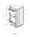
Figure 1 is a perspective view of a shower box according to the invention; -
Figure 2 is a perspective view of a part of the shower box ofFigure 1 illustrating a step of its assembly; -
Figures 3a-3b are cross-section views of a detail of the part of the shower box inFigure 2 showing a further step of its assembly; -
Figure 4 is a partially phantom perspective view of a detail of shower box inFigure 1 illustrating a further step of its assembly; -
Figures 5a-5b are partially phantom side views of the detail inFigure 4 ; -
Figures 6a and 6c are perspective views of the detail inFigure 4 in a further assembly step of the shower box according to two different embodiments; -
Figures 6b and 6b illustrate respectively a side and cross-section views of the detail according to the embodiments inFigures 6a and 6c ; -
Figure 7 illustrates a side and a cross-section view s of the detail inFigure 4 in a further step of assembling the shower box according to a further possible embodiment; -
Figure 8 is a perspective view of a detail of a detail of the shower box provided with additional elements and intermediate members according to different embodiments of the invention; -
Figure 9 is a perspective view of the additional elements associable to the shower box according to different possible embodiments of the invention; -
Figure 10a is a perspective view of a further additional element associable to the shower box, andFigure 10b illustrates in cross-section two steps of assembling such further additional element to the shower box. - With reference to the figures,
reference number 1 indicates a shower box.Shower box 1 defines on one of its inner sides ashower compartment 2, in which an user can have a shower when theshower box 1 is assembled. -
Shower box 1 comprises amain structure 3 defining the above mentionedshower compartment 2.Main structure 3 can have a closed structure, in other words such to define by itself theshower compartment 2, or an open structure, in other words such to define theshower compartment 2 for example with walls of a bathroom, whichshower box 1 can be abutted against. With reference for example toFigure 1 , themain structure 3 is an open structure, comprising only two sides, adapted therefore to define theshower compartment 2 with one or more walls of the bathroom. Obviously, it is possible to provide different shapes to themain structure 2, for example it can be provided with one, three, or four sides. - The
main structure 3 can be differently shaped. According to a possible embodiment, it comprises aframe 4 definingopenings 5 on each side.Such openings 5 can be for example provided with transparent panels made of glass or cut-glass, or can be also opaque. At at least one of saidopenings 5 for example a door for enteringshower compartment 2 can be further provided. Themain structure 3 can for example comprisecross members 6 andposts 7 connected to each other so that to define the above mentionedopenings 5. - The
shower box 1 comprises one or moreadditional elements 8 associated to themain structure 3. Theadditional elements 5 can be arranged on the outer side (in other words on the side opposite to the side where it is made theshower compartment 2, as shown for example inFigure 1 ), and/or on the inner side. - The
additional elements 8 can be of different types. In an illustratively non limiting way,additional elements 8 can comprise: - a wrapper holder 8';
- a
toilet paper holder 8"; - differently-shaped shelves 8'";
-
wall boards 8iv; - a
clothes horse 8v; - a magazine stand 8vi.
- The
additional elements 8 are advantageously located in a raised position, in other words, with reference to a normal state of use of theshower box 1, over the shower box base. In this way, besides gaining more volume in the bathroom, the bathroom floor can be easily accessed and therefore the cleaning thereof is simplified. - The above mentioned
additional elements 8 are associated to themain structure 3 by one ormore support members 9 connected to themain structure 2.Such support members 9 can comprise horizontally located cross members or vertically located posts. Preferably, thesupport members 9 as posts or cross members, extend according to rectilinear extension axes. With reference to the attached figures, thesupport members 9 are in the shape of posts. Thesupport members 9 can be connected to themain structure 3 at its outer side (as shown for example inFigure 1 ) and/or its inner side, facing theshower compartment 2. - In order to connect the
additional elements 8 and themain structure 3 to each other, theshower box 1 comprises suitable means 10 for reciprocally connecting them. Particularly, such connecting means 10 comprise afixing member 11 which is coupable to agroove 12 formed in thesupport members 9. Particularly, thefixing member 11 is coupable to thegroove 12 according to two different arrangements. In a free arrangement, thefixing member 11 is capable of sliding inside thegroove 12. Therefore, it is possible to position thefixing member 11 in any position in thegroove 12 and therefore in any position relative to thesupport member 9. In a fixed arrangement, the fixing member is instead capable of maintaining a fixed position ingroove 12 and therefore with respect to supportmember 9. Therefore, thefixing member 11 can be positioned, as desired, along thegroove 12 and fixed in a desired position. Therefore, as it will be explained in the following, the position of theadditional elements 8 is related to the position of thefixing member 11 in thegroove 12, consequently in theshower box 1 according to the invention it is possible to position, as desired, theadditional elements 8 along the cross members or posts formingsupport members 9 and fix them in such position. - Advantageously, the
groove 12 longitudinally extends along the cross members or posts forming thesupport member 9 and is preferably formed by a cavity, accessible by an user when thesupport member 9 is connected to themain structure 3. Particularly, thegroove 12 is formed on a face opposite to the face facing themain structure 3 when thesupport member 9 is connected to themain structure 3 itself. - With reference to the connection of the
support member 9 to themain structure 3, according to a possible embodiment, the posts or cross members forming thesupport member 9, comprise one ormore openings 13 for coupling the connecting elements, particularly connectingscrews 14 located in themain structure 2 in positions corresponding to the positions of thecoupling openings 13 of thesupport member 9. For example,such coupling openings 13 can be provided in thecross members 6 and/orposts 7 of themain structure 2, and thecoupling openings 13 can be provided at opposite ends of thesupport members 9. Thecoupling openings 13 are advantageously arranged on the side of the fixing members opposite to the side which thegroove 12 is formed in. - Advantageously, the
coupling openings 13 comprises a first and asecond portions 13', 13" having different sizes (Figure 2 ). Particularly, the first portion 13' has sizes greater than thesecond portion 13". Moreover, the first portion 13' has an extension greater than the one of the connectingscrew 14 heads, while thesecond portion 13" has an extension less than the one of such connectingscrews 14 heads. In this way, thesupport member 9 can be connected to themain structure 3 by inserting the connectingscrews 14 incoupling openings 13 at the first portion 13' (Figure 3a ). Then, thesupport member 9 can be moved with respect to themain structure 3, preferably along the longitudinal extension direction of thesame support member 9, so that the connectingscrews 14 heads engaging thesecond portion 13" of theopenings 13 are prevented from become loose from the latter (Figure 3b ). The operation of assembly thesupport member 9 is therefore simple and does not necessarily require skilled technicians. - Referring again to the
groove 12 of thesupport member 9, according to a possible embodiment, its cross section (in other words orthogonally to the longitudinal extension axis of the support member 9) has a profile having a first portion 12' andsecond portions 12" having an extension greater than the first portion 12' (Figure 4 ). The first and thesecond portions 12', 12" are relatively arranged so that thesecond portion 12" is accessible through the first portion 12'. With reference toFigure 2 , for example, the first portion 12' faces the outer side of the shower box, so that thesecond portion 12", positioned inside thesupport member 9, is accessible from the outer side through the first portion 12'. According to the embodiment shown in the figures, the first and thesecond portions 12', 12" of thegroove 12 have, referring again to the cross-section, a rectangular shape. According to this particular shape, the cross section of thesecond portion 12" has a width L and a height H defining a plane orthogonal to the longitudinal extension axis of thegroove 12. - Obviously, other embodiments can be alternatively provided, for
example groove 12 can have a dovetail shape. - Advantageously, the fixing
member 11 is shaped so that it can take the above mentioned free and fixed arrangements in saidgroove 12. Particularly, according to a possible embodiment, the fixingmember 11 comprises aninsert 15 having a first and asecond portions 15', 15", wherein the first portion 15' is overlapped with thesecond portion 15". The first and thesecond portions 15', 15" of theinsert 15 are reciprocally arranged so that the first portion 15' of theinsert 15 can be received in the first portion 12' of thegroove 12, and thesecond portion 15" of theinsert 15 can be received in thesecond portion 12" of thegroove 12. Therefore, the first portion 15' of theinsert 15 has generally dimensions and sizes less than thesecond portion 15" of theinsert 15. - The
second portion 15" of theinsert 15 has an elongated shape, having a longest size D1 and a shortest size D2 (Figure 5 ). Thesecond portion 15" ofinsert 15 has further a third size, coinciding with its height, preferably slightly less than the height H of thesecond portion 12" of thegroove 12. According to a possible embodiment, thesecond portion 15" of theinsert 15 is substantially shaped as a parallelepiped. Advantageously, the longest size D1 of thesecond portion 15" of theinsert 15 has an extension greater than width L of thesecond portion 12" of thegroove 12, while the shortest size D2 has an extension less than the width L of thesecond portion 12" of thegroove 12. In this way, theinsert 15 by rotating in thegroove 12 can take the above mentioned free and fixed arrangements. Particularly, in a first position, the longest size D1 of the first portion 15' of the insert is perpendicular to the longitudinal extension direction of thegroove 12, and therefore theinsert 15 is blocked by interference fit in thegroove 12 since, as said, the longest size D1 is greater than the width L of the groove 12 (Figure 5b ). Such position of theinsert 15 in the groove forms therefore the above mentioned fixed arrangement. - In a second position, instead, the longest size D1 of the
second portion 15" of theinsert 15 is approximately aligned with longitudinal extension direction ofgroove 12 and therefore theinsert 15 can freely slide inside thesame groove 12 since, as said, the second size D2 is smaller than width L of groove 12 (Figure 5a ). Such position of theinsert 15 in thegroove 12 forms therefore the above mentioned free arrangement. Accordingly, theinsert 15 can be inserted in thegroove 12, for example at one of thesupport member 9 ends, in the second position and can slide to the desired area ofgroove 12. Once theinsert 15 has reached such area, it can be taken to the fixed arrangement by rotating the sameinside groove 12. - Advantageously, in order to prevent the
insert 15 from jamming in thegroove 12, theinsert 15 ends 22, extending along the shortest size D2, are radiused (Figure 5a ). Preferably, such ends 22 form constant radius arcs connecting the sides ofinsert 15, extending along longest size D1. - Referring to the first portion 15' of
insert 15, it has preferably a cylindrical shape, so that it can rotate without jamming inside the first portion 12' of thegroove 12. Advantageously, the first portion 15' of theinsert 15 comprises anotch 16 arranged in its upper end, in other words in the area accessible through the first portion 12' of thegroove 12 when theinsert 15 is positioned inside the groove 12(Figures 5a and5b ). In this way, theinsert 15 can be easily handled for example by a screwdriver so that it can switch between the fixed arrangement and the free arrangement. - Advantageously, the
insert 12 comprises a threadedhole 17, preferably extending concentrically to the cylindrical first portion 15' of theinsert 15 itself. Threadedhole 17 enables to connect theinsert 15, and therefore thesupport member 9, to theadditional elements 8 or tointermediate elements 18 which are in turn connected to suchadditional elements 8. The connection can be done by suitable connecting screws 19. - Referring for example to
Figures 6a-6d , they show examples ofintermediate elements 18 connected to theinsert 15 by connectingscrews 19. InFigures 6a-6b ,intermediate elements 18 are supports having a L-shape for positioning, for example, a wallboard or magazine stand, while inFigures 6c-6d intermediate elements 18 have the shape of cramps for abutting shelves. Theintermediate elements 18 advantageously comprise a throughhole 20receiving connecting screws 19, which are screwed in the threadedholes 17 of theinserts 15, in the fixed arrangement. The through holes 20 are shaped so that the corresponding heads of the connectingscrews 19 are stopped in the throughholes 20 in order to prevent theadditional elements 19 from becoming loose. In the same way,additional elements 8 can be fixed to theinsert 15, without requiring the provision of theintermediate elements 18. Referring for example toFigure 7 , the additional element has the shape of a wrapper holder 8' and is fixed to theinsert 15 in the same way as previously described with reference to the L-shape supports inFigures 6a-6b and the cramps ofFigures 6c-6d . - With further advantage, in order to prevent rotations with respect to the
support member 9 ofadditional elements 8, when directly connected to thesupport 9, or of theintermediate elements 18, theadditional elements 8 and/or theintermediate members 18 comprise a projectingportion 21 adapted to be inserted in thegroove 12, particularly in its first portion 12'. The presence of the projectingportion 21 has further the function of simplifying the assembly operation because it enables to orient according to the correct position theadditional elements 8 and/orintermediate members 18 with respect to supportmembers 9. - According to the described operations, it is therefore possible to connect the intermediate elements 18 (as for example shown in
Figures 6a-6d ) and/or directly the additional elements 8 (as for example shown inFigure 7 ) to thesupport elements 9. With reference toFigure 8 , it shows: - a wrapper holder 8' and
toilet paper holder 8" directly fixed to thecorresponding support members 9 having the shape of posts; - pairs of two intermediate elements 18' having the shape of cramps for positioning, for example, shelves 8'" having different sizes (such as for example those shown in
Figure 9 ); - two
intermediate elements 18" having the shape of L supports for positioning for example amagazine stand 8vi such as for example that shown inFigure 10a . The latter, particularly, is advantageously provided with an inverted-L support 23, complementary toL support 18", in order to obtain a shape coupling, as shown for example inFigure 10b . - From the above provided description, a person skilled in the art can appreciate that the shower box, according to the invention, enables to save space in a small-sized environment since it makes possible to associate additional elements to the main structure of the shower box itself, therefore avoiding to arrange such additional elements in the scarce available space.
- The person skilled in the art can also appreciate that the shower box, according to the invention, can be assembled also by unskilled persons. The particular shape of the connecting means, in particular of the insert locatable in the groove of the support members, makes easy the assembly operations.
- To the described embodiments of the shower box according to the invention, the person skilled in the art, in order to meet specific contingent needs, can make several additions, modifications, or substitutions of the elements with other operatively equivalent elements, without departing from the scope of the attached claims.
Claims (8)
- Shower box (1) comprising:- a main structure (3) defining at least partially a shower compartment (2) on an inner side thereof;- one or more support members (9) connected to the main structure (3);- one or more additional elements (8) associated to the main structure (3) on its inner side and/or on its outer side opposite to the inner side by means of said one or more support members (9);- means (10) for connecting the one or more additional elements (8) to the one or more support members (9),
wherein said one or more support members (9) comprise a groove (12) and said connecting means (10) comprise a fixing member (11) coupleable to said groove (12) according to a free arrangement, wherein the fixing member (11) is capable of sliding in said groove (12), and according to a fixed arrangement, wherein the fixing member (11) is capable of maintaining a fixed position inside said groove (12), characterized in that said groove (12) has a cross section comprising a first portion (12') and a second portion (12") having an extension greater than the first portion (12'), said second portion (12") of the groove (12) being accessible through said first portion (12') of the groove (12), wherein said fixing member (11) comprises an insert (15) having a first portion (15') adapted to be housed in said first portion (12') of the groove (12) and a second portion (15") adapted to be housed in said second portion (12") of the groove (12), said second portion (12") of the insert (12) having an elongated shape with a longest size (D1) and a shortest size (D2), said shortest size (D2) having an extension smaller than the width (L) of said second portion (12") of the groove (12), and said longest size (D1) having an extension greater than the width (L) of said second portion (12") of the groove (12), such that the insert (15) can take in the groove (12) a first position wherein the insert (15) is interference locked in the groove (12) and a second position wherein insert (12) freely slides in the groove (12), said first position corresponding to said fixed arrangement and said second position corresponding to said free arrangement of the fixing member (11). - Shower box (1) according to claim 1, wherein said one or more support members (9) comprise vertical posts and/or horizontal cross members, said groove (12) being formed by a cavity longitudinally extending along at least a portion of said length of said cross members and/or posts.
- Shower box (1) according to any preceding claim, wherein the ends of said insert (12), extending along said shortest side (D2) are radiused, in order to prevent said insert (12) from jamming when it moves between said first and second positions in the groove (12).
- Shower box (1) according to any preceding claim, wherein said first portion (15') of insert (15) comprises a notch (16) for moving the insert (15) in groove (12) between said first and second positions by inserting a screwdriver through said first portion (12') of groove (12).
- Shower box (1) according to any preceding claim, wherein said fixing member (11) comprises a threaded hole (17) for connecting through a threaded member (19) of the fixing member (11) itself by said additional elements (8) and/or by intermediate elements (18) for connecting the fixing member (11) by said additional elements (8).
- Shower box (1) according to any preceding claim, wherein said additional elements (8) and/or said intermediate elements (18) comprise a projecting portion (21) adapted to be inserted in said groove (12) in order to prevent rotations with respect to said support members (9).
- Shower box (1) according to any preceding claim, wherein said support members (9) comprise one or more coupling openings (13) having a first portion (13') and a second portion (13") having an extension shorter than the one of the first portion (13'), wherein one or more connecting screws (14) are associated to said main structure (3), said connecting screws being provided of heads in positions corresponding to the coupling openings (13) of the support members (9), so that the support members (9) are connected by inserting the connecting screws (14) heads in the coupling openings (13) at their first portion (13') and then by moving the support members (9) so that the connecting screws (14) heads engage the second portion (13") of the coupling openings (14).
- Shower box (1) according to any preceding claim, wherein said additional elements (8) are selected in the group consisting in: a wrapper holder, toilet paper holder, shelf, wall board, clothes horse, magazine stand.
Applications Claiming Priority (1)
| Application Number | Priority Date | Filing Date | Title |
|---|---|---|---|
| IT001074A ITMI20121074A1 (en) | 2012-06-20 | 2012-06-20 | SHOWER BOX WITH ASSOCIATED ACCESSORY ELEMENTS |
Publications (1)
| Publication Number | Publication Date |
|---|---|
| EP2676586A1 true EP2676586A1 (en) | 2013-12-25 |
Family
ID=46758847
Family Applications (1)
| Application Number | Title | Priority Date | Filing Date |
|---|---|---|---|
| EP13171531.0A Withdrawn EP2676586A1 (en) | 2012-06-20 | 2013-06-11 | Shower box with associated additional elements |
Country Status (2)
| Country | Link |
|---|---|
| EP (1) | EP2676586A1 (en) |
| IT (1) | ITMI20121074A1 (en) |
Cited By (1)
| Publication number | Priority date | Publication date | Assignee | Title |
|---|---|---|---|---|
| CN108451409A (en) * | 2018-02-13 | 2018-08-28 | 南安市景燕电子科技有限公司 | Space-saving bathroom bathroom frame |
Citations (7)
| Publication number | Priority date | Publication date | Assignee | Title |
|---|---|---|---|---|
| US4035097A (en) * | 1975-03-21 | 1977-07-12 | Pierre Bachand | Knockdown connector and guideway assembly |
| JPH044960U (en) * | 1990-04-27 | 1992-01-17 | ||
| AU674401B2 (en) * | 1993-04-08 | 1996-12-19 | Michael Ronald Morris | A connector for a shopfitting system |
| CA2259720A1 (en) * | 1999-02-08 | 1999-04-24 | Rousseau Metal Inc. | Assembly for adjustably mounting an accessory on a rail |
| WO2003027403A1 (en) * | 2001-09-21 | 2003-04-03 | Hansgrohe Ag | Unit for mounting plumbing fixtures |
| EP1428942A2 (en) | 2002-12-13 | 2004-06-16 | Hansgrohe AG | Support for shower head |
| US20060191066A1 (en) * | 2005-02-23 | 2006-08-31 | Johnson Mark A | Shower door storage assembly |
-
2012
- 2012-06-20 IT IT001074A patent/ITMI20121074A1/en unknown
-
2013
- 2013-06-11 EP EP13171531.0A patent/EP2676586A1/en not_active Withdrawn
Patent Citations (7)
| Publication number | Priority date | Publication date | Assignee | Title |
|---|---|---|---|---|
| US4035097A (en) * | 1975-03-21 | 1977-07-12 | Pierre Bachand | Knockdown connector and guideway assembly |
| JPH044960U (en) * | 1990-04-27 | 1992-01-17 | ||
| AU674401B2 (en) * | 1993-04-08 | 1996-12-19 | Michael Ronald Morris | A connector for a shopfitting system |
| CA2259720A1 (en) * | 1999-02-08 | 1999-04-24 | Rousseau Metal Inc. | Assembly for adjustably mounting an accessory on a rail |
| WO2003027403A1 (en) * | 2001-09-21 | 2003-04-03 | Hansgrohe Ag | Unit for mounting plumbing fixtures |
| EP1428942A2 (en) | 2002-12-13 | 2004-06-16 | Hansgrohe AG | Support for shower head |
| US20060191066A1 (en) * | 2005-02-23 | 2006-08-31 | Johnson Mark A | Shower door storage assembly |
Cited By (1)
| Publication number | Priority date | Publication date | Assignee | Title |
|---|---|---|---|---|
| CN108451409A (en) * | 2018-02-13 | 2018-08-28 | 南安市景燕电子科技有限公司 | Space-saving bathroom bathroom frame |
Also Published As
| Publication number | Publication date |
|---|---|
| ITMI20121074A1 (en) | 2013-12-21 |
Similar Documents
| Publication | Publication Date | Title |
|---|---|---|
| EP3453014B1 (en) | A display unit | |
| JP4955215B2 (en) | Wall storage device | |
| EP2676586A1 (en) | Shower box with associated additional elements | |
| KR20170034061A (en) | Assembly type container box with mounted accessary | |
| KR101306720B1 (en) | Assembly Type Cabinet | |
| KR20080097612A (en) | Variable cabinet | |
| CN110107790B (en) | Wall hanging device and display | |
| JP3176670U (en) | partition | |
| KR101017074B1 (en) | Sliding Coupling Device for Partition | |
| JP5334036B2 (en) | Panel connection device and desktop panel using the same | |
| JP5670784B2 (en) | Shelf support structure | |
| JP3117746U (en) | furniture | |
| KR101555963B1 (en) | Wall mount position adjustment member Furniture | |
| JP2006187401A (en) | Assembly type enclosure | |
| JP2005351032A (en) | Building | |
| KR102172503B1 (en) | Bookshelf with varialble sliding door | |
| JP5276296B2 (en) | Storage rack | |
| KR200401434Y1 (en) | a picture frame | |
| US20140339972A1 (en) | Furniture unit | |
| JP2012120732A (en) | Desk apparatus | |
| JP6821264B2 (en) | shelf | |
| JP6294936B1 (en) | Shelf structure | |
| JP6868373B2 (en) | Buddhist altar | |
| KR20160101557A (en) | Retractable cabinet | |
| JP6843562B2 (en) | Storage furniture |
Legal Events
| Date | Code | Title | Description |
|---|---|---|---|
| PUAI | Public reference made under article 153(3) epc to a published international application that has entered the european phase |
Free format text: ORIGINAL CODE: 0009012 |
|
| AK | Designated contracting states |
Kind code of ref document: A1 Designated state(s): AL AT BE BG CH CY CZ DE DK EE ES FI FR GB GR HR HU IE IS IT LI LT LU LV MC MK MT NL NO PL PT RO RS SE SI SK SM TR |
|
| AX | Request for extension of the european patent |
Extension state: BA ME |
|
| STAA | Information on the status of an ep patent application or granted ep patent |
Free format text: STATUS: THE APPLICATION IS DEEMED TO BE WITHDRAWN |
|
| 18D | Application deemed to be withdrawn |
Effective date: 20140626 |