EP2676280B1 - Anordnung zum kühlen einer spule und umrichter - Google Patents
Anordnung zum kühlen einer spule und umrichter Download PDFInfo
- Publication number
- EP2676280B1 EP2676280B1 EP12702414.9A EP12702414A EP2676280B1 EP 2676280 B1 EP2676280 B1 EP 2676280B1 EP 12702414 A EP12702414 A EP 12702414A EP 2676280 B1 EP2676280 B1 EP 2676280B1
- Authority
- EP
- European Patent Office
- Prior art keywords
- coil
- insulating means
- winding
- ducts
- arrangement
- Prior art date
- Legal status (The legal status is an assumption and is not a legal conclusion. Google has not performed a legal analysis and makes no representation as to the accuracy of the status listed.)
- Active
Links
Images




Classifications
-
- H—ELECTRICITY
- H01—ELECTRIC ELEMENTS
- H01F—MAGNETS; INDUCTANCES; TRANSFORMERS; SELECTION OF MATERIALS FOR THEIR MAGNETIC PROPERTIES
- H01F27/00—Details of transformers or inductances, in general
- H01F27/08—Cooling; Ventilating
- H01F27/085—Cooling by ambient air
-
- H—ELECTRICITY
- H01—ELECTRIC ELEMENTS
- H01F—MAGNETS; INDUCTANCES; TRANSFORMERS; SELECTION OF MATERIALS FOR THEIR MAGNETIC PROPERTIES
- H01F27/00—Details of transformers or inductances, in general
- H01F27/28—Coils; Windings; Conductive connections
- H01F27/32—Insulating of coils, windings, or parts thereof
- H01F27/322—Insulating of coils, windings, or parts thereof the insulation forming channels for circulation of the fluid
Definitions
- the invention relates to an arrangement for cooling a coil and a converter.
- coils have a winding which is usually arranged around a coil core.
- the coil winding has a coil axis, so that the coil winding can be produced wound around the coil axis in the circumferential direction.
- Coils are used as inductors in electrical appliances, for example as components of filters, such as mains side filters or the like.
- the invention is therefore based on the object to develop a coil assembly, wherein the cooling of the coil to be improved.
- the object is achieved in the arrangement for cooling a coil according to the features specified in claim 1 and in the inverter according to the features indicated in claim 12.
- the arrangement is provided for cooling a coil, which has a winding arranged on a coil core, the arrangement comprising a coil, a fan and at least one air guiding means, wherein channels are arranged in the winding region of the coil, wherein the air flow generated by the fan is at least partially conducted by means of the air guide into the channels.
- the advantage here is that by means of the arrangement of channels in the winding region of the coil, a particularly effective cooling of the coil can be achieved.
- a fan is provided, which makes an active cooling feasible. In this way, a very effective cooling is thus achievable.
- the coil winding is surrounded by a first insulating means, in particular insulating paper, in particular mineral fiber paper, wherein a second insulating means is disposed overlapping with the first insulating means which projects beyond the axial region covered by the coil winding and functions as an air guiding means, in particular so that an air flow generated by the fan is supplied to the channels.
- a first insulating means in particular insulating paper, in particular mineral fiber paper
- a second insulating means is disposed overlapping with the first insulating means which projects beyond the axial region covered by the coil winding and functions as an air guiding means, in particular so that an air flow generated by the fan is supplied to the channels.
- first and second insulating means are made of the same material.
- the advantage here is that without special material and / or special storage of another component, the second insulating is available.
- the same insulating paper can be used as the first and second insulating means.
- an air guide can be produced and the cooling in a simple and cost-effective manner can be improved.
- channels are equally spaced in the circumferential direction, in particular three, four, five or more channels are arranged on one, in particular the same, radial distance.
- the channels are formed by means of respective hollow parts, which are provided in the Wicklungsberiech, in particular wrapped.
- the advantage here is that the hollow parts predetermine the formation of the channels and thus independent of the winding of the channel cross-section is determined.
- the channels together with their walls, so the walls of the hollow parts, insulating.
- the channels and / or the hollow parts are each formed cuboid.
- the advantage here is that a particularly simple production is possible.
- the cuboid flat executable and thus effective cooling can be achieved.
- the channels and / or the hollow parts are each formed sickle-shaped, wherein the sickle extends in the circumferential direction, in particular wherein the sickle has a substantially constant radial extent.
- the radial width a at the center or geometric center of gravity of a channel cross section and the length b in the circumferential direction or tangential direction are selected such that the ratio a / b is between 0.05 and 0.2.
- the length b and the radius r of the center point or center of gravity are selected such that b / r is between 0.5 and 2.
- the advantage here is that the channels are very narrow executable, so are only slightly extended in the direction of Spulenachscardi radial direction, and in the circumferential direction or tangential direction, So are substantially parallel to the respective winding layer, extended as long as possible.
- one of the narrow channel cross-section despite its increased flow resistance is well flowed through, because the air supply due to the air guide, in particular as a result of the second insulating, lossless is passed into the channels and therefore the fan power is used optimally used to overcome the flow resistance. In this way, therefore, an effective cooling air flow can be generated and thus the most uniform and efficient cooling of the respective adjacent to the channel winding layer or winding layers.
- a channel between the winding region of the coil and the spool core is arranged, in particular so that the associated hollow part touches the spool core, and / or the hollow part of another channel is surrounded by the winding region.
- the coil is used as a throttle and / or in a filter assembly comprising at least one capacitor used.
- the advantage here is that high currents and power through the coil are feasible, since it has an effective cooling.
- the coil core is designed as a laminated core and / or has legs which are connected at their respective end portions with a respective yoke, in particular wherein the coil core is formed rectangular.
- an air-conducting means connected to the housing of the fan touches the second insulating means, in particular so that an otherwise closed flow channel leading from the fan to the channels in the winding area is formed by the fan to the channels in the winding area.
- the second insulating means is held at its end remote from the first insulating and / or the coil end forming and / or guided by a holding part and / or towards the second insulating bent-up tabs of a stamped and bent part, in particular foot part,
- the coil core is held by the stamped and bent part, in particular screw-connected to the stamped and bent part.
- the advantage here is that the outstanding area is held shaping in a simple and cost-effective manner.
- a second insulating means a less rigid material can be used, such as insulating paper or the like.
- the arrangement comprises at least a second coil, in particular identically constructed coil, wherein the second insulating means both coils overlapping the respective first insulating means for supplying the cooling air flow to the arranged in the winding regions of the coils channels.
- inverter Important features of the inverter are that of the emerging from the channels air flow is directed by a channel to the environment, which is limited by a housing wall and a Heilableitsch.
- the advantage here is that an effective cooling is easily achievable.
- the power electronics of the inverter heated air is supplied through a channel of the environment, which is at least partially limited by Luftableitstoff.
- the advantage here is that the two hot air, so exhaust air, channels are directly adjacent to each other can be arranged.
- the arrangement in the axial direction so Spulenachs512, axially held on both sides.
- the advantage here is that an improved Mechanical stabilization, in particular against Rüttelschwingungen, can be achieved.
- heat from the coil core can be discharged on both sides, ie at its lower edge to the base plate and at its upper edge to another with the housing part and heat-conducting connected holding part.
- the coil assembly is connected to a stamped and bent part and held by this, wherein upturned tabs of the stamped and bent part shape holding the second insulating means,
- the punched-bent part on the one hand has the holding function for the spool core and thus also for the entire coil.
- the stamped and bent part predetermines the shape for the lower edge of the second insulating means.
- the coil is castable, so that coil winding, first and second insulating means with the casting agent, in particular a casting resin, are impregnated and thus stabilized.
- the casting agent in particular a casting resin
- hereby seals are produced.
- an airtight connection can be produced, since without the casting only a contact between stamped and bent part made of steel and second insulating material made of insulating paper can be achieved.
- a fan 62 is shown in the housing of the inverter, whereby a cooling air flow is supplied by means of further guidance through a hood-like air guide 40 channels 10 of a coil.
- the channels 10 are spaced from each other in the coil winding 22 of the coil, in particular, wherein some of the channels are regularly spaced from each other.
- the cooling air flow exits at the end region of the coil facing away from the fan 62 and is discharged into the environment through an air discharge duct 60.
- FIGS. 1 to 7 a concrete embodiment of an inverter and the coil arrangement provided therein is shown.
- the coil is an example of a throttle, such as actuator throttle and / or filter inductance.
- the core of the coil is composed of yoke parts (20, 23) and leg parts 21 which are arranged between the yoke parts 20 and 23.
- the spool core, in particular its lower yoke part 23 is screw-connected to a foot part 1, which thus acts as a lower holding part.
- the upper yoke part 20 is screw-connected by means of the screw connection 6 to a retaining plate 7, which in turn is connected to the housing of the converter and thus supports the coil core at the upper end region.
- a retaining plate 7 which in turn is connected to the housing of the converter and thus supports the coil core at the upper end region.
- the coil core is surrounded and wrapped by the winding 22, the electrical connection lines are led out as busbars 8 from the coil.
- the busbars 8 lead to the other components of the power electronics of the inverter.
- the winding 22 of the coil hollow parts are inserted and then wrapped, so that axially extending channels 10 are formed, which serve for carrying out a cooling medium, such as air.
- the channels are preferably equally spaced in the circumferential direction.
- a first insulating means 5 is arranged, in particular, the winding 22 is wrapped with insulating paper 5, for electrical insulation.
- a mineral fiber paper is used as insulating paper.
- a second insulating means 2 in particular the same insulating paper, has an overlap with the first insulating means and extends in the axial direction to the edge 4th
- the second insulating means 2 thus extends in the axial direction from the axial area covered by the winding 22 in the direction of the foot part. Thus, therefore, the second insulating means 2 protrudes beyond the axial region of the coil winding 22.
- a holding part 11 is screwed to the foot part 1, whereby thus the second insulating means 2 even around the coil and an equally constructed, adjacent coil can be guided around.
- the coils are directly adjacent, so that the air flow can not escape into the space between the two coils.
- the projecting portion of the second insulating means is achieved by formed on the foot, in particular bent-up tabs 70, a further shaping guide for the second insulating means.
- the foot part 1 is preferably designed as a stamped and bent part.
- the protruding portion of the second insulating means 2 forms an air guiding means. Because together with the air guide 40, a limit for the airflow generated by the fan 62 is created. In this case, the housing of the fan 62, that is, the outer air boundary of the fan 62, connected to the air guide 40, as in FIG. 6 shown.
- the coil winding is soaked in the production of the coil with a casting resin, which hardens.
- This casting resin not only improves the mechanical stability, in particular the fixing of the coil winding 22 but also improves the electrical insulation.
- the first insulating means 5 arranged in the coil winding between the winding layers of the coil winding 22 and arranged on the outer surface of the coil is mechanically stabilized, in particular stiffer.
- this is at least partially solidified via the first insulating 5 axially superior second insulating means 2 with the casting resin, in particular stiffened.
- the casting resin and / or an adhesive or filler by means of the casting resin and / or an adhesive or filler, a substantially tight connection between the second insulating means 2 and foot part 1 can be achieved.
- the word "dense” here refers to the tightness of the cooling air flow generated by the fan, so that only insignificant proportions of the cooling air flow between foot part 1 and second insulating 2 emerge in the space surrounding the coil in the inverter.
- the air flow generated by the fan 62 is thus guided to those in the channels 10 and thus through the winding region of the winding 22.
- the air flow flows out and is limited only by the intermediate wall 51 and housing parts of the inverter. In this case, the air flow is then led out through an air discharge duct 60 formed by a housing wall 41 and an air discharge plate 50 into the environment.
- the converter also has a signal electronics 65 for generating pulse-width-modulated drive signals for controllable power semiconductor switches of a power electronics 66 of the converter.
- the heat generated by the power electronics 66 is passed through a heat sink to an air stream which is guided in the air channel 67, which is at least partially limited by the Beerableitblech 50.
- the air flow and the m Heilableitkanal 60 guided air flow directly adjacent and spaced only on the Lucasableitblech 50 from each other. Since the temperature difference between the two adjacent air streams is small, no significant heat flow between the two air streams is effected.
- the number of parts is reduced because the Luftableitblech 50 can be used as a respective air flow limiting means.
- a filter capacitor 64 which is also executable as a capacitor arrangement, arranged, which forms a filter with the coil, in particular with the entire coil assembly. In this way, loads on the network can be reduced by harmonics generated by the converter and / or high-frequency interference.
- connection means 9 in particular connector part, from the winding area.
- the channel cross sections are very narrow and elongated executable in the invention.
- the narrow direction is substantially radial and the long extension is substantially tangential or directed in the circumferential direction.
- the radial width a at the center or geometric center of gravity of the channel cross section and the length b in the circumferential direction or tangential direction are selected such that the ratio a / b is between 0.05 and 0.2.
- the length b and the radius of the center point or center of gravity are selected such that b / r is between 0.5 and 2.
- each channel 10 is associated with one or more channels 10 in the radial direction, wherein the mutually associated channels are then radially spaced from each other.
Landscapes
- Engineering & Computer Science (AREA)
- Power Engineering (AREA)
- Transformer Cooling (AREA)
- Insulating Of Coils (AREA)
Description
- Die Erfindung betrifft eine Anordnung zum Kühlen einer Spule und einen Umrichter.
- Es ist allgemein bekannt, dass Spulen eine Wicklung aufweisen, die meist um einen Spulenkern herum angeordnet ist. Die Spulenwicklung weist dabei eine Spulenachse auf, so dass die Spulenwicklung in Umfangsrichtung um die Spulenachse herum gewickelt herstellbar ist. Spulen werden als Induktivitäten verwendet in elektrischen Geräten, beispielsweise auch als Komponente von Filtern, wie netzseitige Filter oder dergleichen.
- Aus der
EP 0 092 204 A2 ist eine Induktionsspule bekannt. - Aus der
WO 2009/046733 A1 ist ein elektrischer Wicklungskörper bekannt. - Aus der
DE 37 32 670 A1 ist eine Anordnung eines Transformators und eines Mastes in einem Freileitungsnetz zur Elektrizitätsübertragung bekannt. - Der Erfindung liegt daher die Aufgabe zugrunde, eine Spulenanordnung weiterzubilden, wobei die Kühlung der Spule verbessert werden soll.
- Erfindungsgemäß wird die Aufgabe bei der Anordnung zum Kühlen einer Spule nach den in Anspruch 1 und bei dem Umrichter nach den in Anspruch 12 angegebenen Merkmalen gelöst.
- Wichtige Merkmale der Erfindung bei der Anordnung sind, dass die Anordnung zum Kühlen einer Spule vorgesehen ist, welche eine auf einem Spulenkern angeordnete Wicklung aufweist,
wobei die Anordnung eine Spule, einen Lüfter und zumindest ein Luftleitmittel aufweist,
wobei im Wicklungsbereich der Spule Kanäle angeordnet sind,
wobei der vom Lüfter erzeugte Luftstrom zumindest teilweise mittels des Luftleitmittels in die Kanäle geleitet wird. - Von Vorteil ist dabei, dass mittels des Anordnens von Kanälen im Wicklungsbereich der Spule eine besonders effektive Entwärmung der Spule erreichbar ist. Außerdem ist ein Lüfter vorgesehen, der eine aktive Entwärmung ausführbar macht. Auf diese Weise ist somit eine sehr wirksame Entwärmung erreichbar.
- Bei einer vorteilhaften Ausgestaltung ist die Spulenwicklung von einem ersten Isoliermittel, insbesondere Isolierpapier, insbesondere Mineralfaserpapier, umgeben,
wobei ein zweites Isoliermittel überlappend zum ersten Isoliermittel angeordnet ist, welches über den von der Spulenwicklung überdeckten axialen Bereich hinausragt und als Luftleitmittel fungiert,
insbesondere so dass ein vom Lüfter erzeugter Luftstrom den Kanälen zugeleitet wird. Von Vorteil ist dabei, dass die Spule außen, also an ihrem äußeren Umfang elektrisch isolierbar ist. Somit ist eine Unfallgefahr bei Berührung verminderbar. Außerdem wird am ersten ein zweites Isoliermittel befestigt, so dass ein Luftleitmittel entsteht. Im Befestigungsbereich ist also die elektrische Isolation weiter verbessert und zusätzlich entsteht ein überragender Bereich, welcher eine zusätzliche Funktion ausführbar macht, nämlich das Luftleiten des vom Lüfter angetriebenen Luftstroms zu den Kanälen hin. Auf diese Weise ist die Luftleitung und somit auch die Entwärmung verbessert. - Infolge der aktiven Belüftung der Kanäle sind diese Kanäle eng ausführbar und daher eine kompakte leistungsfähige Wicklung herstellbar.
- Bei einer vorteilhaften Ausgestaltung sind erstes und zweites Isoliermittel aus demselben Material gefertigt. Von Vorteil ist dabei, dass ohne besonderen Materialaufwand und/oder besondere Bevorratung einer weiteren Komponente das zweite Isoliermittel verfügbar ist.
- Insbesondere ist als erstes und zweites Isoliermittel dasselbe Isolierpapier verwendbar. Durch bloßes unterschiedliches Positionieren des Papiers ist somit ein Luftleitmittel herstellbar und die Entwärmung in einfacher und kostengünstiger Weise verbesserbar.
- Bei einer vorteilhaften Ausgestaltung sind Kanäle in Umfangsrichtung gleichmäßig voneinander beabstandet, insbesondere drei, vier, fünf oder mehr Kanäle sich auf einem, insbesondere gleichen, Radialabstand angeordnet sind. Von Vorteil ist dabei, dass eine möglichst gleichmäßige Entwärmung der Spule ausführbar und somit eine möglichst gleichmäßige Temperaturverteilung erreichbar ist.
- Bei einer vorteilhaften Ausgestaltung sind die Kanäle mittels jeweiliger Hohlteile gebildet, die im Wicklungsberiech vorgesehen, insbesondere umwickelt sind. Von Vorteil ist dabei, dass die Hohlteile die Ausformung der Kanäle vorgeben und somit unabhängig von der Wicklung der Kanalquerschnitt bestimmt ist. Außerdem wirken die Kanäle samt ihrer Wandung, also der Wände der Hohlteile, isolierend.
- Bei einer vorteilhaften Ausgestaltung sind die Kanäle und/oder die Hohlteile jeweils quaderförmig ausgebildet. Von Vorteil ist dabei, dass eine besonders einfache Herstellung ermöglicht ist. Außerdem sind die Quader flach ausführbar und somit eine effektive Entwärmung erreichbar.
- Bei einer vorteilhaften Ausgestaltung sind die Kanäle und/oder die Hohlteile jeweils sichelförmig ausgebildet, wobei die Sichel sich in Umfangsrichtung erstreckt, insbesondere wobei die Sichel eine im Wesentlichen konstante radiale Ausdehnung aufweist. Von Vorteil ist dabei, dass eine effektive Entwärmung und eine hohe Wickeldichte erreichbar ist.
- Bei einer vorteilhaften Ausgestaltung sind die radiale Breite a am Mittelpunkt oder geometrischen Schwerpunkt eines Kanalquerschnitts und die Länge b in Umfangsrichtung oder Tangentialrichtung derart gewählt, dass das Verhältnis a/b zwischen 0,05 und 0,2 beträgt.
- Insbesondere sind die Länge b und der Radius r des Mittelpunkts beziehungsweise Schwerpunkts derart gewählt, dass b/r zwischen 0,5 und 2 beträgt. Von Vorteil ist dabei, dass die Kanäle sehr schmal ausführbar sind, also in zur Spulenachsrichtung radialer Richtung nur geringfügig ausgedehnt sind, und in Umfangsrichtung oder Tangentialrichtung, also im Wesentlichen parallel zur jeweiligen Wickellage, möglichst lang ausgedehnt sind. Dabei ist ein der enge Kanalquerschnitt trotz seines erhöhten Strömungswiderstandes gut durchströmbar, weil die Luftzufuhr infolge der Luftleitmittel, insbesondere infolge des zweiten Isoliermittels, verlustfrei in die Kanäle geleitet wird und daher der die Lüfterleistung im wesentlichen optimal genutzt wird zur Überwindung des Strömungswiderstandes. Auf diese Weise ist also ein wirkungsvoller Kühlluftstrom erzeugbar und somit eine möglichst gleichmäßige und leistungsfähige Entwärmung der zum Kanal jeweils benachbarten Wickellage beziehungsweise Wickellagen.
- Bei einer vorteilhaften Ausgestaltung ist ein Kanal zwischen dem Wicklungsbereich der Spule und dem Spulenkern angeordnet, insbesondere also berührt das zugehörige Hohlteil den Spulenkern, und/oder ist das Hohlteil eines anderen Kanals vom Wicklungsbereich umgeben. Von Vorteil ist dabei, dass auch Wärme des Spulenkerns abtransportierbar ist über einen Kanal und die Spulenwicklung somit an ihrer Innenseite und in ihrem Mittelbereich entwärmt wird. Somit ist eine besonders gleichmäßige Temperaturverteilung erreichbar.
- Bei einer vorteilhaften Ausgestaltung ist die Spule als Drossel verwendet und/oder in einer Filteranordnung, umfassend zumindest einen Kondensator, eingesetzt. Von Vorteil ist dabei, dass hohe Ströme und Leistungen durch die Spule führbar sind, da sie eine effektive Kühlung aufweist.
- Bei einer vorteilhaften Ausgestaltung ist der Spulenkern als Blechpaket ausgeführt und/oder weist Schenkel auf, die an ihren jeweiligen Endbereichen mit einem jeweiligen Joch verbunden sind, insbesondere wobei der Spulenkern rechteckförmig ausgebildet ist. Von Vorteil ist dabei, dass ein modularer Aufbau erreicht ist, so dass mit wenigen bevorrateten Typen von Teilen eine hohe Varianz von Spulenkernen einfach herstellbar ist.
- Bei einer vorteilhaften Ausgestaltung berührt ein mit dem Gehäuse des Lüfters verbundenes Luftleitmittel das zweite Isoliermittel, insbesondere so dass ein vom Lüfter zu den Kanälen im Wicklungsbereich führender, ansonsten geschlossener Strömungskanal vom Lüfter zu den Kanälen im Wicklungsbereich ausgebildet ist. Von Vorteil ist dabei, dass wenig Strömungsverluste auftreten und somit eine effektive Entwärmung erreichbar ist.
- Bei einer vorteilhaften Ausgestaltung ist das zweite Isoliermittel an seinem von dem ersten Isoliermittel und/oder der Spulenwicklung abgewandten Endbereich formgebend gehalten und/oder geführt von einem Halteteil und/oder in Richtung zum zweiten Isoliermittel hochgebogenen Laschen eines Stanz-Biegeteils, insbesondere Fußteils,
- insbesondere wobei der Spulenkern vom Stanz-Biegeteil gehalten ist, insbesondere mit dem Stanz-Biegeteil schraubverbunden ist. Von Vorteil ist dabei, dass der überragende Bereich formgebend gehalten ist in einfacher und kostengünstiger Weise. Somit ist als zweites Isoliermittel ein wenig steifes Material verwendbar, wie beispielsweise Isolierpapier oder dergleichen. Bei im zugehörigen Elektrogerät auftretenden Rüttelschwingungen ist eine ausreichende Stabilisierung erreichbar, da das zweite Isoliermittel an seinem ersten Randbereich mit dem ersten Isoliermittel verbunden, insbesondere verklebt, ist und an seinem zweiten Randbereich von den hochgebogenen Laschen des Stanz-Biegeteils stabilisiert und/oder gehalten ist.
- Bei einer vorteilhaften Ausgestaltung weist die Anordnung zumindest eine zweite Spule, insbesondere gleichartig aufgebaute Spule, auf, wobei das zweite Isoliermittel beide Spulen das jeweilige erste Isoliermittel überlappend umgibt zur Zuleitung des Kühlluftstroms an die in den Wicklungsbereichen der Spulen angeordneten Kanäle. Von Vorteil ist dabei, dass kein zusätzliches Teil vorrätig gehalten werden muss für die Herstellung sondern dasselbe zweite Isoliermittel verwendbar ist wie bei der ersten Spule.
- Wichtige Merkmale bei dem Umrichter sind, dass der wird der aus den Kanälen austretende Luftstrom mittels eines Kanals an die Umgebung geleitet, welcher begrenzt ist durch eine Gehäusewand und ein Luftableitmittel. Von Vorteil ist dabei, dass eine effektive Entwärmung in einfacher Weise erreichbar ist.
- Bei einer vorteilhaften Ausgestaltung wird von der Leistungselektronik des Umrichters aufgewärmte Luft durch einen Kanal der Umgebung zugeführt, welcher zumindest teilweise begrenzt ist vom Luftableitmittel. Von Vorteil ist dabei, dass die beiden Warmluft-, also Abluft-, Kanäle direkt aneinander angrenzend anordenbar sind.
- Bei einer vorteilhaften Ausgestaltung ist die Anordnung in axialer Richtung, also Spulenachsrichtung, axial beidseitig gehalten. Von Vorteil ist dabei, dass eine verbesserte mechanische Stabilisierung, insbesondere gegen Rüttelschwingungen, erreichbar ist. Außerdem ist Wärme vom Spulenkern beidseitig abführbar, also an dessen unterem Rand zur Fußplatte hin und an dessen oberen Rand an ein weiteres mit dem Gehäuseteil auch wärmeleitend verbundenes Halteteil.
- Bei einer vorteilhaften Ausgestaltung ist die Spulenanordnung auf einem Stanz-Biegeteil verbunden und von diesem gehalten, wobei hochgebogene Laschen des Stanz-Biegeteils formgebend das zweite Isoliermittel halten,
- insbesondere wobei zumindest ein Halteteil zum weiteren formgebenden Halten des zweiten Isoliermittels vorgesehen ist, insbesondere wobei dieses Halteteil am Stanz-Biegeteil befestigt ist. Von Vorteil ist dabei, dass das Stanz-Biegeteil einerseits die Haltefunktion für den Spulenkern und somit auch für die gesamte Spule aufweist. Außerdem gibt das Stanz-Biegeteil die Form für den unteren Rand des zweiten Isoliermittels vor.
- Die Spule ist vergießbar, so dass Spulenwicklung, erstes und zweites Isoliermittel mit dem Gussmittel, insbesondere ein Gießharz, tränkbar und somit stabilisierbar sind. Außerdem werden hiermit Abdichtungen herstellbar. Insbesondere ist auf diese Weise zwischen zweiten Isoliermittel und Stanz-Biegeteil eine luftdichte Verbindung herstellbar, da ohne das Gussmittel nur ein Berühren zwischen Stanz-Biegeteil aus Stahl und zweiten Isoliermittel aus Isolierpapier erreichbar ist.
- Weitere Vorteile ergeben sich aus den Unteransprüchen. Die Erfindung ist nicht auf die Merkmalskombination der Ansprüche beschränkt. Für den Fachmann ergeben sich weitere sinnvolle Kombinationsmöglichkeiten von Ansprüchen und/oder einzelnen Anspruchsmerkmalen und/oder Merkmalen der Beschreibung und/oder der Figuren, insbesondere aus der Aufgabenstellung und/oder der sich durch Vergleich mit dem Stand der Technik stellenden Aufgabe.
- Die Erfindung wird nun anhand von schematischen Abbildungen näher erläutert:
- In der
Figur 1 ist eine Schrägansicht der erfindungsgemäßen Spule gezeigt. - In der
Figur 2 ist eine Schrägansicht durch eine längs angeschnittene Spule gezeigt. - In der
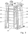
Figur 3 ist eine Schrägansicht durch eine quer angeschnittene Spule gezeigt. - In der
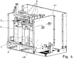
Figur 4 ist ein angeschnittener Umrichter mit eingebauten Spulen gezeigt. - In der
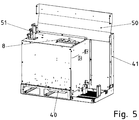
Figur 5 ist der angeschnittene Umrichter mit mittels von Gehäuseteilen umgebenen Spulen. - In der
Figur 6 ist ein Querschnitt durch den Umrichter gezeigt. - In der
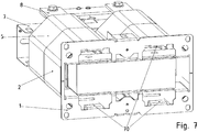
Figur 7 ist eine Schrägansicht auf die Unterseite des Umrichters gezeigt, so dass die hochgebogenen Laschen 70 erkennbar sind, welche formgebend das zweite Isoliermittel 2 berühren. - In der
Figur 8 ist das Schema der Entwärmung des erfindungsgemäßen Umrichters gezeigt, wobei auch alle Teile nur schematisch skizziert sind. - Wie in
Figur 8 gezeigt ist im Gehäuse des Umrichters ein Lüfter 62 angeordnet, wodurch ein Kühlluftstrom mittels weiterer Führung durch ein haubenartiges Luftleitmittel 40 Kanälen 10 einer Spule zugeführt wird. Die Kanäle 10 sind im Wicklungsberiech 22 der Spule voneinander beabstandet angeordnet, insbesondere wobei einige der Kanäle voneinander regelmäßig beabstandet sind. - Somit tritt der Kühlluftstrom am vom Lüfter 62 abgewandten Endbereich der Spule aus und wird durch einen Luftableitkanal 60 in die Umgebung abgeführt.
- In den nun weiter beschriebenen
Figuren 1 bis 7 ist eine konkrete Ausführung eines Umrichters und der in ihm vorgesehenen Spulenanordnung gezeigt. - Die Spule ist beispielhaft eine Drossel, wie Stellerdrossel und/oder Filterinduktivität.
- Der Kern der Spule ist aus Jochteilen (20, 23) und Schenkelteilen 21 zusammengesetzt, die zwischen den Jochteilen 20 und 23 angeordnet sind.
- Der Spulenkern, insbesondere sein unteres Jochteil 23 ist schraubverbunden mit einem Fußteil 1, welches somit als unteres Halteteil fungiert.
- Das obere Jochteil 20 ist schraubverbunden mittels der Schraubverbindung 6 mit einem Halteblech 7, das wiederum mit dem Gehäuse des Umrichters verbunden ist und somit den Spulenkern am oberen Endbereich abstützt. Somit ist eine erhöhte Stabilität gegen mechanische Schwingungen erreichbar.
- Der Spulenkern ist umgeben und umwickelt von der Wicklung 22, deren elektrische Anschlussleitungen als Stromschienen 8 herausgeführt sind aus der Spule. Die Stromschienen 8 führen zu den weiteren Bauteilen der Leistungselektronik des Umrichters.
- Beim Wickeln der Wicklung 22 der Spule werden Hohlteile eingelegt und dann umwickelt, so dass axial verlaufende Kanäle 10 entstehen, die zum Durchführen eines Kühlmediums, wie Luft dienen. Die Kanäle sind in Umlaufsrichtung vorzugsweise gleichmäßig voneinander beabstandet.
- An ihrem äußeren Umfang ist ein erstes Isoliermittel 5 angeordnet, insbesondere ist die Wicklung 22 mit Isolierpapier 5 umwickelt, zur elektrischen Isolierung. Das erste Isoliermittel endet in axialer Richtung am Rand 3.
- Vorzugsweise wird als Isolierpapier ein Mineralfaserpapier verwendet.
- Ein zweites Isoliermittel 2, insbesondere dasselbe Isolierpapier, weist einen Überlapp auf mit dem ersten Isoliermittel und reicht in axialer Richtung bis zum Rand 4.
- Das zweite Isoliermittel 2 erstreckt sich also in axialer Richtung vom von der Wicklung 22 überdeckten axialen Bereich hinaus in Richtung des Fußteils. Somit ragt also das zweite Isoliermittel 2 über den axialen Bereich der Spulenwicklung 22 hinaus.
- Zur Formgebung wird ein Halteteil 11 am Fußteil 1 angeschraubt, wodurch somit das zweite Isoliermittel 2 sogar um die Spule und eine ebenso aufgebaute, benachbarte Spule herumführbar ist. Dabei sind die Spulen direkt benachbart, so dass der Luftstrom nicht entweichen kann in den Zwischenraum zwischen den beiden Spulen.
- Der überragende Abschnitt des zweiten Isoliermittels wird durch am Fußteil ausgebildete, insbesondere hochgebogene, Laschen 70eine weitere formgebende Führung für das zweite Isoliermittel erreicht. Vorzugsweise ist hierzu das Fußteil 1 als Stanz-Biegeteil ausgeführt.
- Der überragende Abschnitt des zweiten Isoliermittels 2 bildet ein Luftleitmittel. Denn zusammen mit dem Luftleitmittel 40 ist eine Begrenzung für den vom Lüfter 62 erzeugten Luftstrom geschaffen. Dabei ist das Gehäuse des Lüfters 62, also die äußere Luftbegrenzung des Lüfters 62, mit dem Luftleitmittel 40 verbunden, wie in
Figur 6 gezeigt. - Die Spulenwicklung wird beim Herstellen der Spule getränkt mit einem Gießharz, welches aushärtet. Dieses Gießharz verbessert nicht nur die mechanische Stabilität, insbesondere das Fixieren der Spulenwicklung 22 sondern verbessert auch die elektrische Isolation. Ebenso wird das in der Spulenwicklung zwischen den Wickellagen der Spulenwicklung 22 angeordnete und an der äußeren Oberfläche der Spule angeordnete erste Isoliermittel 5 mechanisch stabilisiert, insbesondere steifer.
- Ebenso ist das das zumindest teilweise über das erste Isoliermittel 5 axial überragende zweite Isoliermittel 2 mit dem Gießharz verfestigt, insbesondere versteift. Darüber hinaus ist mittels des Gießharzes und/oder einem Klebstoff oder Füllstoff eine im Wesentlichen dichte Verbindung zwischen zweitem Isoliermittel 2 und Fußteil 1 erreichbar. Das Wort "dicht" bezieht sich hierbei auf die Dichtigkeit für den vom Lüfter erzeugten Kühlluftstrom, so dass nur unwesentliche Anteile des Kühlluftstroms zwischen Fußteil 1 und zweitem Isoliermittel 2 austreten in den die Spule umgebenden Raumbereich im Umrichter.
- Der vom Lüfter 62 erzeugte Luftstrom wird also zu den in die Kanäle 10 geführt und somit durch den Wickelbereich der Wicklung 22. Am axial anderen Mündungsbereich der Kanäle 10 strömt der Luftstrom heraus und wird erst durch die Zwischenwand 51 sowie Gehäuseteile des Umrichters begrenzt. Dabei wird der Luftstrom dann durch einen von einer Gehäusewand 41 und einem Luftableitblech 50 gebildeten Luftableitkanal 60 herausgeführt in die Umgebung.
- Der Umrichter weist auch eine Signalelektronik 65 zur Erzeugung pulsweitenmodulierter Ansteuersignale für steuerbare Leistungshalbleiterschalter einer Leistungselektronik 66 des Umrichters auf. Die von der Leistungselektronik 66 erzeugte Wärme wird über einen Kühlkörper an einen Luftstrom geleitet, der im Luftkanal 67 geführt ist, der zumindest teilweise auch von dem Luftableitblech 50 begrenzt wird. Somit sind der Luftstrom und der m Luftableitkanal 60 geführte Luftstrom direkt benachbart und nur über das Luftableitblech 50 voneinander beabstandet. Da die Temperaturdifferenz zwischen den beiden benachbarten Luftströmen geringfügig ist, ist kein wesentlicher Wärmefluss zwischen den beiden Luftströmen bewirkt.
- Allerdings ist die Anzahl der Teile reduziert, da das Luftableitblech 50 als jeweiliges Luftstrombegrenzungsmittel einsetzbar ist.
- Im Umrichter, insbesondere im Raumbereich der Leistungselektronik, ist auch ein Filterkondensator 64, der auch als Kondensatoranordnung ausführbar ist, angeordnet, der mit der Spule, insbesondere mit der gesamten Spulenanordnung, ein Filter bildet. Auf diese Weise sind Belastungen des Netzes mit vom Umrichter erzeugten Oberschwingungen und/oder Hochfrequenz-Störungen reduzierbar.
- In der Spulenwicklung wird auch ein Temperatursensor angeordnet, dessen Anschlüsse zu dem Anschlussmittel 9, insbesondere Steckverbinderteil, aus dem Wicklungsbereich herausgeführt sind. Somit ist eine insbesondere bei Wartungsarbeiten oder Reparaturen einfach und schnell betätigbare Verbindung hergestellt.
- Die Kanalquerschnitte sind bei der Erfindung sehr schmal und länglich ausführbar. Dabei ist die schmale Richtung im Wesentlichen radial und die lange Ausdehnung im Wesentlichen tangential oder in Umfangsrichtung gerichtet. Die radiale Breite a am Mittelpunkt oder geometrischen Schwerpunkt des Kanalquerschnitts und die Länge b in Umfangsrichtung oder Tangentialrichtung sind derart gewählt, dass das Verhältnis a/b zwischen 0,05 und 0,2 beträgt. Außerdem ist die Länge b und der Radius des Mittelpunkts beziehungsweise Schwerpunkts derart gewählt, dass b/r zwischen 0,5 und 2 beträgt.
- In einem weiteren erfindungsgemäßen Ausführungsbeispiel sind auch statt zwei mehrere gleichartig aufgebaute Spulen direkt benachbart anordenbar und das zweite Isoliermittel 2 um die äußere Berandung dieser Spulengruppe als Luftleitmittel herumführbar, wobei wiederum am Fußteil ausgebildete, insbesondere hochgebogene Laschen 70 eine weitere formgebende Führung für das zweite Isoliermittel bilden.
- Bei anderen erfindungsgemäßen Ausführungsbeispielen ist in radialer Richtung jedem Kanal 10 auch einer oder mehrere Kanäle 10 zugeordnet, wobei die zueinander zugeordneten Kanäle dann radial beabstandet voneinander sind.
-
- 1 Fußteil
- 2 zweites Isoliermittel
- 3 Endkante des ersten Isoliermittels
- 4 Endkante des zweiten Isoliermittels
- 5 erstes Isoliermittel
- 6 Schraubverbindung
- 7 Halteblech
- 8 Stromschiene
- 9 Anschlussmittel, insbesondere Steckverbinderteil
- 10 Kühlkanal
- 11 Halteteil
- 20 Jochteil
- 21 Schenkelteil
- 22 Wicklung
- 23 Jochteil
- 40 Luftleitmittel
- 41 Gehäusewand
- 50 Luftableitblech
- 51 Zwischenwand
- 60 Luftableitkanal
- 61 Halteteil
- 62 Lüfter
- 64 Filterkondensator
- 65 Signalelektronik
- 66 Leistungselektronik
- 67 Luftkanal
- 70 hochgebogene Laschen
Claims (15)
- Anordnung zum Kühlen einer Spule, welche eine auf einem Spulenkern (20, 21,23) angeordnete Wicklung aufweist,
wobei die Anordnung eine Spule, einen Lüfter (62) und zumindest ein Luftleitmittel (40) aufweist,
wobei im Wicklungsbereich der Spule axial verlaufende Kanäle (10) angeordnet sind,
wobei der vom Lüfter (62) erzeugte Luftstrom mittels des Luftleitmittels (40) in die Kanäle geleitet wird, dadurch gekennzeichnet, dass die Spulenwicklung von einem ersten aus Isolierpapier bestehenden Isoliermittel (5), insbesondere Mineralfaserpapier, umgeben ist,
wobei ein zweites Isoliermittel (2) überlappend zum ersten Isoliermittel (5) angeordnet ist, welches zweite Isoliermittel (2) über den von der Spulenwicklung überdeckten axialen Bereich hinausragt und als weiteres Luftleitmittel fungiert, so dass ein vom Lüfter (62) erzeugter Luftstrom den Kanälen (10) zugeleitet wird, wobei das mit dem Gehäuse des Lüfters (62) verbundene_Luftleitmittel (40) das zweite Isoliermittel (2) berührt, so dass ein vom Lüfter (62) zu den Kanälen im Wicklungsbereich führender, ansonsten geschlossener Strömungskanal vom Lüfter (62) zu den Kanälen im Wicklungsbereich ausgebildet ist,
wobei erstes und zweites Isoliermittel (2, 5) aus demselben Material gefertigt sind
wobei die Kanäle (10) in Umfangsrichtung gleichmäßig voneinander beabstandet sind,
wobei drei, vier, fünf oder mehr Kanäle (10) auf dem gleichen Radialabstand angeordnet sind, wobei die Kanäle jeweils quaderförmig ausgebildet sind. - Anordnung nach Anspruch 1,
dadurch gekennzeichnet, dass
die Kanäle (10) mittels jeweiliger Hohlteile gebildet sind, die im Wicklungsbereich vorgesehen, insbesondere umwickelt sind. - Anordnung nach Anspruch 2 dadurch gekennzeichnet, dass
die Hohlteile jeweils quaderförmig ausgebildet sind. - Anordnung nach mindestens einem der Ansprüche 1 oder 2, dadurch gekennzeichnet, dass
die Kanäle (10) und/oder die Hohlteile jeweils sichelförmig ausgebildet sind, wobei die Sichel sich in Umfangsrichtung erstreckt, insbesondere wobei die Sichel eine im Wesentlichen konstante radiale Ausdehnung aufweist. - Anordnung nach mindestens einem der vorangegangenen Ansprüche,
dadurch gekennzeichnet, dass
die radiale Breite a am Mittelpunkt oder geometrischen Schwerpunkt eines Kanalquerschnitts und die Länge b in Umfangsrichtung oder Tangentialrichtung derart gewählt sind, dass das Verhältnis a/b zwischen 0,05 und 0,2 beträgt. - Anordnung nach mindestens einem der vorangegangenen Ansprüche,
dadurch gekennzeichnet, dass
die Länge b und der Radius r des Mittelpunkts beziehungsweise Schwerpunkts derart gewählt, dass b/r zwischen 0,5 und 2 beträgt. - Anordnung nach mindestens einem der vorangegangenen Ansprüche,
dadurch gekennzeichnet, dass
ein Kanal zwischen dem Wicklungsbereich der Spule und dem Spulenkern angeordnet ist, insbesondere also das zugehörige Hohlteil den Spulenkern berührt, und/oder das Hohlteil eines anderen Kanals vom Wicklungsbereich umgeben ist. - Anordnung nach mindestens einem der vorangegangenen Ansprüche,
dadurch gekennzeichnet, dass
die Spule als Drossel verwendbar ist und/oder in einer Filteranordnung, umfassend zumindest einen Kondensator, einsetzbar ist. - Anordnung nach mindestens einem der vorangegangenen Ansprüche,
dadurch gekennzeichnet, dass
der Spulenkern als Blechpaket ausgeführt ist und/oder Schenkel aufweist, die an ihren jeweiligen Endbereichen mit einem jeweiligen Joch verbunden sind, insbesondere wobei der Spulenkern rechteckförmig ausgebildet ist. - Anordnung nach mindestens einem der vorangegangenen Ansprüche,
dadurch gekennzeichnet, dass
das zweite Isoliermittel (2) an seinem von dem ersten Isoliermittel (5) und/oder der Spulenwicklung abgewandten Endbereich formgebend gehalten und/oder geführt ist von einem Halteteil und/oder in Richtung zum zweiten Isoliermittel (2) hochgebogenen Laschen eines Stanz-Biegeteils, insbesondere Fußteils (1),
wobei der Spulenkern vom Stanz-Biegeteil gehalten ist, insbesondere mit dem Stanz-Biegeteil schraubverbunden ist,
und/oder dass
Spulenwicklung, erstes und zweites Isoliermittel (2, 5) mit einem ausgehärteten Gießharz versehen sind, wobei zwischen zweitem Isoliermittel (2) und Fußteil (1) das Gießharz oder ein Klebstoff oder Füllstoff eine für den vom Lüfter (62) erzeugten Kühlluftstrom im Wesentlichen luftdichte Abdichtung bewirkt ist. - Anordnung nach mindestens einem der vorangegangenen Ansprüche,
dadurch gekennzeichnet, dass
die Anordnung zumindest eine zweite Spule, insbesondere gleichartig aufgebaute Spule, aufweist, wobei das zweite Isoliermittel (2) beide Spulen das jeweilige erste Isoliermittel (5) überlappend umgibt zur Zuleitung des Kühlluftstroms an die in den Wicklungsbereichen der Spulen angeordneten Kanäle (10). - Umrichter mit einer Anordnung nach mindestens einem der vorangegangenen Ansprüche,
wobei der Umrichter Signalelektronik (65) zur Erzeugung pulsweitenmodulierter Ansteuersignale für steuerbare Leistungshalbleiterschalter einer Leistungselektronik (66) des Umrichters aufweist,
dadurch gekennzeichnet, dass
der aus den Kanälen (10) austretende Luftstrom mittels eines Kanals an die Umgebung geleitet wird, welcher begrenzt ist durch eine Gehäusewand und ein Luftableitmittel. - Umrichter nach mindestens einem der vorangegangenen Ansprüche,
dadurch gekennzeichnet, dass
von der Leistungselektronik des Umrichters aufgewärmte Luftdurch einen Kanal der Umgebung zugeführt wird, welcher zumindest teilweise begrenzt ist vom Luftableitmittel. - Umrichter nach mindestens einem der vorangegangenen Ansprüche,
dadurch gekennzeichnet, dass
die Anordnung in axialer Richtung, also Spulenachsrichtung, axial beidseitig gehalten ist. - Umrichter nach mindestens einem der vorangegangenen Ansprüche,
dadurch gekennzeichnet, dass
die Spulenanordnung auf einem Stanz-Biegeteil verbunden und von diesem gehalten ist,
wobei hochgebogene Laschen des Stanz-Biegeteils formgebend das zweite Isoliermittel (2) halten,
insbesondere wobei zumindest ein Halteteil zum weiteren formgebenden Halten des zweiten Isoliermittels (2) vorgesehen ist, insbesondere wobei dieses Halteteil am Stanz-Biegeteil befestigt ist.
Applications Claiming Priority (2)
| Application Number | Priority Date | Filing Date | Title |
|---|---|---|---|
| DE102011011302.9A DE102011011302B4 (de) | 2011-02-15 | 2011-02-15 | Anordnung zum Kühlen einer Spule und Umrichter |
| PCT/EP2012/000216 WO2012110187A1 (de) | 2011-02-15 | 2012-01-18 | Anordnung zum kühlen einer spule und umrichter |
Publications (2)
| Publication Number | Publication Date |
|---|---|
| EP2676280A1 EP2676280A1 (de) | 2013-12-25 |
| EP2676280B1 true EP2676280B1 (de) | 2019-08-28 |
Family
ID=45562941
Family Applications (1)
| Application Number | Title | Priority Date | Filing Date |
|---|---|---|---|
| EP12702414.9A Active EP2676280B1 (de) | 2011-02-15 | 2012-01-18 | Anordnung zum kühlen einer spule und umrichter |
Country Status (3)
| Country | Link |
|---|---|
| EP (1) | EP2676280B1 (de) |
| DE (1) | DE102011011302B4 (de) |
| WO (1) | WO2012110187A1 (de) |
Family Cites Families (14)
| Publication number | Priority date | Publication date | Assignee | Title |
|---|---|---|---|---|
| US3073885A (en) | 1960-09-28 | 1963-01-15 | Gen Electric | Insulating and cooling arrnagement for electrical apparatus |
| DE1941385U (de) | 1961-07-25 | 1966-06-30 | Licentia Gmbh | Zylinderspule mit mehreren, in einem gemeinsamen giessharzkoerper eingelagerten wicklungslagen. |
| DE1921103U (de) | 1965-06-04 | 1965-08-12 | Starkstrom Geraetebau G M B H | Trockentransformator mit forcierter luftkuehlung. |
| DE1912760C3 (de) | 1969-03-13 | 1979-01-25 | Licentia Patent-Verwaltungs-Gmbh, 6000 Frankfurt | Mit axialen Kühlkanälen durchsetzte luftgekühlte Wicklung für Transformatoren, Drosselspulen u.dgl. induktive Geräte |
| DE2104112C3 (de) | 1971-01-29 | 1979-05-10 | Transformatoren Union Ag, 7000 Stuttgart | Verfahren zur Herstellung von Kühlkanälen in einer in Kunstharz vergossenen Wicklung |
| US3939449A (en) | 1975-01-15 | 1976-02-17 | Westinghouse Electric Corporation | Insulated transformer windings |
| US4129938A (en) | 1975-08-25 | 1978-12-19 | Hariolf Hagenbucher | Method of making tubular coils with cooling and insulating channels |
| CA1051103A (en) | 1976-05-31 | 1979-03-20 | Westinghouse Canada Limited | Fluid filled transformer |
| IT8221582U1 (it) | 1982-04-16 | 1983-10-16 | Sirten | Bobina d'induttanza. |
| US4541171A (en) | 1984-04-27 | 1985-09-17 | Westinghouse Electric Corp. | Method of making an electrical transformer |
| DE3732670A1 (de) * | 1987-09-28 | 1989-04-13 | Siemens Ag | Anordnung eines transformators und eines mastes in einem freileitungsnetz zur elektrizitaetsuebertragung |
| JPH0464204A (ja) * | 1990-07-04 | 1992-02-28 | Hitachi Ltd | 樹脂モールドコイルとその製造方法 |
| EP2193530B1 (de) * | 2007-09-28 | 2016-09-14 | Siemens Aktiengesellschaft | Elektrischer wicklungskörper und transformator mit forcierter kühlung |
| CN102696081B (zh) * | 2009-09-11 | 2016-02-24 | Abb研究有限公司 | 包括热管的变压器 |
-
2011
- 2011-02-15 DE DE102011011302.9A patent/DE102011011302B4/de active Active
-
2012
- 2012-01-18 WO PCT/EP2012/000216 patent/WO2012110187A1/de not_active Ceased
- 2012-01-18 EP EP12702414.9A patent/EP2676280B1/de active Active
Non-Patent Citations (1)
| Title |
|---|
| None * |
Also Published As
| Publication number | Publication date |
|---|---|
| WO2012110187A1 (de) | 2012-08-23 |
| EP2676280A1 (de) | 2013-12-25 |
| DE102011011302B4 (de) | 2024-11-14 |
| DE102011011302A1 (de) | 2012-08-16 |
Similar Documents
| Publication | Publication Date | Title |
|---|---|---|
| DE112008002806B4 (de) | Drehende elektrische Maschine | |
| DE112010005769B4 (de) | Transformator | |
| EP1432102A2 (de) | Elektrische Maschine mit Heatpipes | |
| WO2023110769A1 (de) | Rotor für eine elektrische maschine mit einem kühlkanal in einem poltrenner | |
| EP2700146B1 (de) | Dynamoelektrische maschine mit einem blechpaket eines stators und einem selbsttragenden gehäuse | |
| DE102010056430A1 (de) | Elektromotor | |
| EP2148410A1 (de) | Elektrische Maschine mit stufenförmigem Wicklungsaufbau | |
| DE112013003481T5 (de) | Mit Gurt befestigter segmentierter Elektromaschinenkern und Herstellungsverfahren | |
| DE102013201778A1 (de) | Elektrische Maschine mit Ständerdirektkühlung | |
| DE102018105029A1 (de) | Drosselspule | |
| EP0293617A1 (de) | Hochfrequenz-Leistungsübertrager | |
| DE102019124345A1 (de) | Kühlung eines elektrischen Leiters für eine elektrische Maschine | |
| EP2639800B1 (de) | Transformator für ein elektrisch angetriebenes Fahrzeug | |
| EP1045505B1 (de) | Elektrischer, gekühlter Scheibenläufermotor | |
| EP2937973A1 (de) | Rotierende elektrische Maschine | |
| DE102023124497A1 (de) | Stator für eine elektrische Maschine, elektrische Maschine sowie Kraftfahrzeug | |
| EP2804291A1 (de) | Gehäuse für einen Elektromotor | |
| EP0585644B1 (de) | Oberflächengekühlte, geschlossene elektrische Maschine | |
| WO2014117881A1 (de) | Drehfeldmaschine mit aussenläufer, insbesondere in modularer bauweise | |
| DE102012208545A1 (de) | Wassergekühlte elektrische Spule | |
| DE102011011302B4 (de) | Anordnung zum Kühlen einer Spule und Umrichter | |
| EP2982024B1 (de) | Gehäuse für eine elektrische maschine | |
| DE202009011270U1 (de) | Endkappenvorrichtung | |
| DE102005032970B3 (de) | Umrichtermotor | |
| EP2919367A1 (de) | Rotor einer rotierenden elektrischen Maschine |
Legal Events
| Date | Code | Title | Description |
|---|---|---|---|
| PUAI | Public reference made under article 153(3) epc to a published international application that has entered the european phase |
Free format text: ORIGINAL CODE: 0009012 |
|
| 17P | Request for examination filed |
Effective date: 20130916 |
|
| AK | Designated contracting states |
Kind code of ref document: A1 Designated state(s): AL AT BE BG CH CY CZ DE DK EE ES FI FR GB GR HR HU IE IS IT LI LT LU LV MC MK MT NL NO PL PT RO RS SE SI SK SM TR |
|
| DAX | Request for extension of the european patent (deleted) | ||
| STAA | Information on the status of an ep patent application or granted ep patent |
Free format text: STATUS: EXAMINATION IS IN PROGRESS |
|
| 17Q | First examination report despatched |
Effective date: 20170907 |
|
| GRAP | Despatch of communication of intention to grant a patent |
Free format text: ORIGINAL CODE: EPIDOSNIGR1 |
|
| STAA | Information on the status of an ep patent application or granted ep patent |
Free format text: STATUS: GRANT OF PATENT IS INTENDED |
|
| INTG | Intention to grant announced |
Effective date: 20190404 |
|
| GRAS | Grant fee paid |
Free format text: ORIGINAL CODE: EPIDOSNIGR3 |
|
| GRAA | (expected) grant |
Free format text: ORIGINAL CODE: 0009210 |
|
| STAA | Information on the status of an ep patent application or granted ep patent |
Free format text: STATUS: THE PATENT HAS BEEN GRANTED |
|
| AK | Designated contracting states |
Kind code of ref document: B1 Designated state(s): AL AT BE BG CH CY CZ DE DK EE ES FI FR GB GR HR HU IE IS IT LI LT LU LV MC MK MT NL NO PL PT RO RS SE SI SK SM TR |
|
| REG | Reference to a national code |
Ref country code: GB Ref legal event code: FG4D Free format text: NOT ENGLISH |
|
| REG | Reference to a national code |
Ref country code: CH Ref legal event code: EP |
|
| REG | Reference to a national code |
Ref country code: AT Ref legal event code: REF Ref document number: 1173405 Country of ref document: AT Kind code of ref document: T Effective date: 20190915 |
|
| REG | Reference to a national code |
Ref country code: IE Ref legal event code: FG4D Free format text: LANGUAGE OF EP DOCUMENT: GERMAN |
|
| REG | Reference to a national code |
Ref country code: DE Ref legal event code: R096 Ref document number: 502012015209 Country of ref document: DE |
|
| REG | Reference to a national code |
Ref country code: NL Ref legal event code: MP Effective date: 20190828 |
|
| REG | Reference to a national code |
Ref country code: LT Ref legal event code: MG4D |
|
| PG25 | Lapsed in a contracting state [announced via postgrant information from national office to epo] |
Ref country code: FI Free format text: LAPSE BECAUSE OF FAILURE TO SUBMIT A TRANSLATION OF THE DESCRIPTION OR TO PAY THE FEE WITHIN THE PRESCRIBED TIME-LIMIT Effective date: 20190828 Ref country code: PT Free format text: LAPSE BECAUSE OF FAILURE TO SUBMIT A TRANSLATION OF THE DESCRIPTION OR TO PAY THE FEE WITHIN THE PRESCRIBED TIME-LIMIT Effective date: 20191230 Ref country code: HR Free format text: LAPSE BECAUSE OF FAILURE TO SUBMIT A TRANSLATION OF THE DESCRIPTION OR TO PAY THE FEE WITHIN THE PRESCRIBED TIME-LIMIT Effective date: 20190828 Ref country code: SE Free format text: LAPSE BECAUSE OF FAILURE TO SUBMIT A TRANSLATION OF THE DESCRIPTION OR TO PAY THE FEE WITHIN THE PRESCRIBED TIME-LIMIT Effective date: 20190828 Ref country code: NO Free format text: LAPSE BECAUSE OF FAILURE TO SUBMIT A TRANSLATION OF THE DESCRIPTION OR TO PAY THE FEE WITHIN THE PRESCRIBED TIME-LIMIT Effective date: 20191128 Ref country code: LT Free format text: LAPSE BECAUSE OF FAILURE TO SUBMIT A TRANSLATION OF THE DESCRIPTION OR TO PAY THE FEE WITHIN THE PRESCRIBED TIME-LIMIT Effective date: 20190828 Ref country code: NL Free format text: LAPSE BECAUSE OF FAILURE TO SUBMIT A TRANSLATION OF THE DESCRIPTION OR TO PAY THE FEE WITHIN THE PRESCRIBED TIME-LIMIT Effective date: 20190828 Ref country code: BG Free format text: LAPSE BECAUSE OF FAILURE TO SUBMIT A TRANSLATION OF THE DESCRIPTION OR TO PAY THE FEE WITHIN THE PRESCRIBED TIME-LIMIT Effective date: 20191128 |
|
| PG25 | Lapsed in a contracting state [announced via postgrant information from national office to epo] |
Ref country code: LV Free format text: LAPSE BECAUSE OF FAILURE TO SUBMIT A TRANSLATION OF THE DESCRIPTION OR TO PAY THE FEE WITHIN THE PRESCRIBED TIME-LIMIT Effective date: 20190828 Ref country code: ES Free format text: LAPSE BECAUSE OF FAILURE TO SUBMIT A TRANSLATION OF THE DESCRIPTION OR TO PAY THE FEE WITHIN THE PRESCRIBED TIME-LIMIT Effective date: 20190828 Ref country code: AL Free format text: LAPSE BECAUSE OF FAILURE TO SUBMIT A TRANSLATION OF THE DESCRIPTION OR TO PAY THE FEE WITHIN THE PRESCRIBED TIME-LIMIT Effective date: 20190828 Ref country code: GR Free format text: LAPSE BECAUSE OF FAILURE TO SUBMIT A TRANSLATION OF THE DESCRIPTION OR TO PAY THE FEE WITHIN THE PRESCRIBED TIME-LIMIT Effective date: 20191129 Ref country code: RS Free format text: LAPSE BECAUSE OF FAILURE TO SUBMIT A TRANSLATION OF THE DESCRIPTION OR TO PAY THE FEE WITHIN THE PRESCRIBED TIME-LIMIT Effective date: 20190828 Ref country code: IS Free format text: LAPSE BECAUSE OF FAILURE TO SUBMIT A TRANSLATION OF THE DESCRIPTION OR TO PAY THE FEE WITHIN THE PRESCRIBED TIME-LIMIT Effective date: 20191228 |
|
| PG25 | Lapsed in a contracting state [announced via postgrant information from national office to epo] |
Ref country code: TR Free format text: LAPSE BECAUSE OF FAILURE TO SUBMIT A TRANSLATION OF THE DESCRIPTION OR TO PAY THE FEE WITHIN THE PRESCRIBED TIME-LIMIT Effective date: 20190828 |
|
| PG25 | Lapsed in a contracting state [announced via postgrant information from national office to epo] |
Ref country code: PL Free format text: LAPSE BECAUSE OF FAILURE TO SUBMIT A TRANSLATION OF THE DESCRIPTION OR TO PAY THE FEE WITHIN THE PRESCRIBED TIME-LIMIT Effective date: 20190828 Ref country code: EE Free format text: LAPSE BECAUSE OF FAILURE TO SUBMIT A TRANSLATION OF THE DESCRIPTION OR TO PAY THE FEE WITHIN THE PRESCRIBED TIME-LIMIT Effective date: 20190828 Ref country code: RO Free format text: LAPSE BECAUSE OF FAILURE TO SUBMIT A TRANSLATION OF THE DESCRIPTION OR TO PAY THE FEE WITHIN THE PRESCRIBED TIME-LIMIT Effective date: 20190828 Ref country code: IT Free format text: LAPSE BECAUSE OF FAILURE TO SUBMIT A TRANSLATION OF THE DESCRIPTION OR TO PAY THE FEE WITHIN THE PRESCRIBED TIME-LIMIT Effective date: 20190828 Ref country code: DK Free format text: LAPSE BECAUSE OF FAILURE TO SUBMIT A TRANSLATION OF THE DESCRIPTION OR TO PAY THE FEE WITHIN THE PRESCRIBED TIME-LIMIT Effective date: 20190828 |
|
| PG25 | Lapsed in a contracting state [announced via postgrant information from national office to epo] |
Ref country code: SK Free format text: LAPSE BECAUSE OF FAILURE TO SUBMIT A TRANSLATION OF THE DESCRIPTION OR TO PAY THE FEE WITHIN THE PRESCRIBED TIME-LIMIT Effective date: 20190828 Ref country code: CZ Free format text: LAPSE BECAUSE OF FAILURE TO SUBMIT A TRANSLATION OF THE DESCRIPTION OR TO PAY THE FEE WITHIN THE PRESCRIBED TIME-LIMIT Effective date: 20190828 Ref country code: SM Free format text: LAPSE BECAUSE OF FAILURE TO SUBMIT A TRANSLATION OF THE DESCRIPTION OR TO PAY THE FEE WITHIN THE PRESCRIBED TIME-LIMIT Effective date: 20190828 Ref country code: IS Free format text: LAPSE BECAUSE OF FAILURE TO SUBMIT A TRANSLATION OF THE DESCRIPTION OR TO PAY THE FEE WITHIN THE PRESCRIBED TIME-LIMIT Effective date: 20200224 |
|
| REG | Reference to a national code |
Ref country code: DE Ref legal event code: R097 Ref document number: 502012015209 Country of ref document: DE |
|
| PLBE | No opposition filed within time limit |
Free format text: ORIGINAL CODE: 0009261 |
|
| STAA | Information on the status of an ep patent application or granted ep patent |
Free format text: STATUS: NO OPPOSITION FILED WITHIN TIME LIMIT |
|
| PG2D | Information on lapse in contracting state deleted |
Ref country code: IS |
|
| 26N | No opposition filed |
Effective date: 20200603 |
|
| PG25 | Lapsed in a contracting state [announced via postgrant information from national office to epo] |
Ref country code: MC Free format text: LAPSE BECAUSE OF FAILURE TO SUBMIT A TRANSLATION OF THE DESCRIPTION OR TO PAY THE FEE WITHIN THE PRESCRIBED TIME-LIMIT Effective date: 20190828 Ref country code: SI Free format text: LAPSE BECAUSE OF FAILURE TO SUBMIT A TRANSLATION OF THE DESCRIPTION OR TO PAY THE FEE WITHIN THE PRESCRIBED TIME-LIMIT Effective date: 20190828 |
|
| REG | Reference to a national code |
Ref country code: CH Ref legal event code: PL |
|
| REG | Reference to a national code |
Ref country code: BE Ref legal event code: MM Effective date: 20200131 |
|
| PG25 | Lapsed in a contracting state [announced via postgrant information from national office to epo] |
Ref country code: LU Free format text: LAPSE BECAUSE OF NON-PAYMENT OF DUE FEES Effective date: 20200118 |
|
| PG25 | Lapsed in a contracting state [announced via postgrant information from national office to epo] |
Ref country code: CH Free format text: LAPSE BECAUSE OF NON-PAYMENT OF DUE FEES Effective date: 20200131 Ref country code: LI Free format text: LAPSE BECAUSE OF NON-PAYMENT OF DUE FEES Effective date: 20200131 Ref country code: BE Free format text: LAPSE BECAUSE OF NON-PAYMENT OF DUE FEES Effective date: 20200131 |
|
| PG25 | Lapsed in a contracting state [announced via postgrant information from national office to epo] |
Ref country code: IE Free format text: LAPSE BECAUSE OF NON-PAYMENT OF DUE FEES Effective date: 20200118 |
|
| REG | Reference to a national code |
Ref country code: AT Ref legal event code: MM01 Ref document number: 1173405 Country of ref document: AT Kind code of ref document: T Effective date: 20200118 |
|
| PG25 | Lapsed in a contracting state [announced via postgrant information from national office to epo] |
Ref country code: AT Free format text: LAPSE BECAUSE OF NON-PAYMENT OF DUE FEES Effective date: 20200118 |
|
| PG25 | Lapsed in a contracting state [announced via postgrant information from national office to epo] |
Ref country code: MT Free format text: LAPSE BECAUSE OF FAILURE TO SUBMIT A TRANSLATION OF THE DESCRIPTION OR TO PAY THE FEE WITHIN THE PRESCRIBED TIME-LIMIT Effective date: 20190828 Ref country code: CY Free format text: LAPSE BECAUSE OF FAILURE TO SUBMIT A TRANSLATION OF THE DESCRIPTION OR TO PAY THE FEE WITHIN THE PRESCRIBED TIME-LIMIT Effective date: 20190828 |
|
| PG25 | Lapsed in a contracting state [announced via postgrant information from national office to epo] |
Ref country code: MK Free format text: LAPSE BECAUSE OF FAILURE TO SUBMIT A TRANSLATION OF THE DESCRIPTION OR TO PAY THE FEE WITHIN THE PRESCRIBED TIME-LIMIT Effective date: 20190828 |
|
| PGFP | Annual fee paid to national office [announced via postgrant information from national office to epo] |
Ref country code: GB Payment date: 20251204 Year of fee payment: 15 |
|
| PGFP | Annual fee paid to national office [announced via postgrant information from national office to epo] |
Ref country code: FR Payment date: 20251208 Year of fee payment: 15 |
|
| REG | Reference to a national code |
Ref country code: DE Ref legal event code: R084 Ref document number: 502012015209 Country of ref document: DE |
|
| PGFP | Annual fee paid to national office [announced via postgrant information from national office to epo] |
Ref country code: DE Payment date: 20260131 Year of fee payment: 15 |