EP2676011B1 - 3-wellen-verstellgetriebe mit zwei mechanischen anschlägen - Google Patents
3-wellen-verstellgetriebe mit zwei mechanischen anschlägen Download PDFInfo
- Publication number
- EP2676011B1 EP2676011B1 EP11791281.6A EP11791281A EP2676011B1 EP 2676011 B1 EP2676011 B1 EP 2676011B1 EP 11791281 A EP11791281 A EP 11791281A EP 2676011 B1 EP2676011 B1 EP 2676011B1
- Authority
- EP
- European Patent Office
- Prior art keywords
- stop
- shaft
- gear
- adjustment mechanism
- mechanism according
- Prior art date
- Legal status (The legal status is an assumption and is not a legal conclusion. Google has not performed a legal analysis and makes no representation as to the accuracy of the status listed.)
- Not-in-force
Links
- 230000005540 biological transmission Effects 0.000 description 4
- 230000008878 coupling Effects 0.000 description 3
- 238000010168 coupling process Methods 0.000 description 3
- 238000005859 coupling reaction Methods 0.000 description 3
- 238000002485 combustion reaction Methods 0.000 description 2
- RDYMFSUJUZBWLH-UHFFFAOYSA-N endosulfan Chemical compound C12COS(=O)OCC2C2(Cl)C(Cl)=C(Cl)C1(Cl)C2(Cl)Cl RDYMFSUJUZBWLH-UHFFFAOYSA-N 0.000 description 2
- 238000004804 winding Methods 0.000 description 2
- 230000000694 effects Effects 0.000 description 1
- 238000001746 injection moulding Methods 0.000 description 1
- 230000001681 protective effect Effects 0.000 description 1
- 238000005096 rolling process Methods 0.000 description 1
Images

Classifications
-
- F—MECHANICAL ENGINEERING; LIGHTING; HEATING; WEAPONS; BLASTING
- F01—MACHINES OR ENGINES IN GENERAL; ENGINE PLANTS IN GENERAL; STEAM ENGINES
- F01L—CYCLICALLY OPERATING VALVES FOR MACHINES OR ENGINES
- F01L1/00—Valve-gear or valve arrangements, e.g. lift-valve gear
- F01L1/34—Valve-gear or valve arrangements, e.g. lift-valve gear characterised by the provision of means for changing the timing of the valves without changing the duration of opening and without affecting the magnitude of the valve lift
- F01L1/344—Valve-gear or valve arrangements, e.g. lift-valve gear characterised by the provision of means for changing the timing of the valves without changing the duration of opening and without affecting the magnitude of the valve lift changing the angular relationship between crankshaft and camshaft, e.g. using helicoidal gear
- F01L1/352—Valve-gear or valve arrangements, e.g. lift-valve gear characterised by the provision of means for changing the timing of the valves without changing the duration of opening and without affecting the magnitude of the valve lift changing the angular relationship between crankshaft and camshaft, e.g. using helicoidal gear using bevel or epicyclic gear
- F01L2001/3521—Harmonic drive of flexspline type
Definitions
- the invention relates to a 3-shaft adjusting according to the preamble of claim 1 with a rotatably connected to a drive shaft driving part, a rotatably connected to an output shaft driven part and a rotatably connected to an adjusting actuator.
- 3-shaft adjusting are used for example in internal combustion engines for adjusting phase angles, primarily for adjusting the opening and closing times of the gas exchange valves used (camshaft adjuster, phaser for actuator shafts in variable valve trains).
- the phase adjuster is arranged as an actuator in a 3-shaft system.
- Primary power is supplied to the 3-shaft system through the drive shaft (sprocket), which is output through the output shaft (e.g., camshaft).
- the actuator is arranged as a link between the drive shaft and the shaft to be driven in the power flow. It allows a third shaft (adjusting shaft) superimposed on the drive power additionally coupled mechanical power into the shaft system or remove it. As a result, the predetermined by the drive shaft movement function (phase angle) can be changed to the output shaft.
- 3-shaft adjusting gear examples include swash plate gear and mecanical gear which, for example, in the WO 2006/018080 are described. This includes the from the WO 2005/080757 known wave gear and in the US 2007/0051332 A1 and US 2003/0226534 A1 contained gear.
- phasers are known in the art. For example, in DE 10 2004 009 128 A1 . DE 10 2005 059884 A1 and DE 10 2004 038 681 A1 electromechanical camshaft adjuster described.
- an electromechanical camshaft adjuster is known in which the adjusting motor is connected by means of a releasable coupling with the adjusting gear.
- the coupling transmittable to the adjusting torque can be limited. This then acts as a safety clutch.
- a special case of a 3-shaft variable speed is a 2-shaft arrangement in adjusting drives, in which the drive shaft is fixed to the housing, d. H. only power is transferred between the adjusting shaft and the output shaft.
- Such a device serves to convert a drive power inputted at a high speed and a low load into a low-speed and high-load output, and finds application in, for example, automotive type reduction drives and industrial applications, e.g. robotics.
- the adjustment range or drive range is limited by limiting the angle of rotation of one of the three shafts relative to a second shaft or relative to the housing.
- a mechanical stop is used as an integral part of the device.
- the stop between the output shaft and the drive shaft is provided, since the adjusting shaft usually covers an angle of more than 360 °.
- the adjustment shaft which is not limited directly in the adjustment angle or drive angle, is then braked in the case of the stop via the transmission kinematics and the rigidity of the transmission elements as soon as the output side reaches the limit of the rotation angle.
- gear parts can deform so much that they collide with each other and bring the actuator to jamming.
- Farther Gear parts can tire prematurely or must be oversized for normal operation in order to endure the high loads in the case of unbraked stop.
- the object of Einfindung is to form a 3-shaft adjustment such that the pulse loads occurring when reaching a stop in the actuator are damped in their effect.
- a 3-shaft adjusting initially comprises in a known manner with a drive shaft rotatably connectable drive part, a rotatably connected to an output shaft driven part and a rotatably connected to an adjusting shaft of an actuator actuator. Between two of the three shafts, usually between the drive part and the output part, a first mechanical stop for limiting an adjustment angle between the drive shaft and the output shaft is provided.
- a second mechanical stop is now arranged between two other shafts as the first stop. That is, when the first stop is provided between the driving part and the driven part, the second stop may be provided between the actuator and the driving part or the driven part.
- each of the three shafts is thus coupled to at least one of the two stops, and precisely one shaft is coupled to both stops.
- the second mechanical stop may be formed in the simplest case by two stop surfaces, which are placed on the various gear parts (execution corresponding to the first stop). But the two abutment surfaces can also be formed by a run in a gate stop pin
- the second stop may be formed in alternative embodiments, for example by a ball, a pin or a similar shaped body, which is guided in a spiral-shaped recess.
- the spiral recess may have a pitch in the axial or radial direction.
- the adjustment angle can be limited in only one adjustment direction or in both adjustment directions.
- the limitation is achieved by mounting the loop belt up to the respective block angle by contact between the windings or with the housing, so that the function of the second stop for limiting the adjustment of the adjusting shaft is represented by the principle of the wrap.
- the torque of the wrap spring acting on the adjusting shaft is much smaller than the moment of the actuator. In the fail-safe case, the moment effective at the adjustment acts in the preferably approaching adjustment direction.
- the invention will be explained below on an electromechanical camshaft adjuster of an internal combustion engine, in which the first mechanical stop is provided between the drive part and the driven part.
- the second mechanical stop according to the invention is advantageously provided in this case between the actuator and the drive part, but may also be formed between the actuator and driven part. The following will only on the variant of the stop between actuator and drive part received.
- the second mechanical stop comprises a reduction gear.
- the width of the secondary adjustment window then depends on the reduction and the adjustment on the output side.
- the reduction gear is in a preferred embodiment, a planetary gear, which comprises a formed with the actuator sun gear, at least one planetary gear and a ring gear.
- a stop is firmly connected to the sprocket while a stop gate is provided either on a planet carrier or on the ring gear.
- the ring gear may be formed in a first embodiment with the sprocket.
- the stop scenery is provided here on the planet carrier.
- the ring gear may be rotatably connected to the drive member.
- the planet carrier is then sprocket-proof.
- the ring gear as such may be arranged separately on the drive member or be formed only in a sector of a ring gear.
- the stop gate is provided, in which a fixedly connected to the drive part stop pin is guided. The ring gear disc can therefore only be rotated by an angle given by the angular range of the guide angle with respect to the drive part.
- Fig. 1 shows a section of an electromechanical camshaft adjuster as a 3-shaft adjustment in a longitudinal sectional view.
- FIGS. 2 and 3 show the camshaft adjuster in different side views.
- the camshaft adjuster comprises a sprocket 01 as a drive part and a camshaft gear 02 as a driven part.
- the adjusting gear is designed as a wave gear.
- Such a camshaft adjuster with wave gear is known in principle to those skilled in the art.
- the adjusting be formed in any known manner.
- a hollow shaft 03 as an actuator is formed with a wave generator 04, which comprises an elliptical inner ring 06, an elliptical outer ring 07 with an outer toothing 08 and roller bodies 09 arranged therebetween.
- the sprocket 01 comprises a first ring gear with an internal toothing 11.
- the ring gear is incorporated directly into the sprocket 01.
- the camshaft gear 02 has an internal toothing 12.
- the number of teeth of the internal toothings 11, 12 differ by one or two teeth.
- the hollow shaft 03 is preferably connected via a coupling with the adjusting shaft of the electric motor.
- the rotor of the electric motor runs at camshaft speed With. By increasing or reducing the rotor speed, it takes place camshaft adjustment to early or late in a conventional manner.
- a stop ring 13 On the sprocket 01 camshaft side in a known manner, a stop ring 13 is provided with a radially inwardly projecting stop lug 14. On Nockenwellenrad 02 a stop plate 16 with stops 17 in the same plane as the stop ring 13 is arranged. A relative rotation between the camshaft and crankshaft is limited by the abutting stop lug 14 with one of the stop surfaces 17 (see also Fig. 3 ).
- the internal teeth 11 of the sprocket 01 is extended on the Verstellwellenseite (in the picture left) in the axial direction and engages in one or more planet gears 18 (see also Fig. 2 ).
- the planet gears 18 roll on an outer toothing 19 of the hollow shaft 03 and are connected to each other by means of a web shaft 21 (planet carrier).
- the web shaft 21 has on its outer periphery a link 22 with stop surfaces 23 (FIG. Fig. 2 ).
- a stop pin 24 is firmly anchored, which is movable relative to the web shaft 21 within the link 22 between the abutment surfaces 23.
- the width of the secondary adjustment window of the second stop depends on the reduction and the adjustment on the output side.
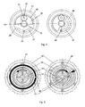
- Fig. 4 shows an alternative embodiment of a second stop with a reduction gear in a 3-shaft adjusting in a side view from the perspective of the adjusting or hollow shaft 03 in two different positions.
- a ring gear 26 is arranged relative to the sprocket 01 rotatably in the adjusting gear.
- the ring gear 26 has a stop gate 27, in which the sprocket-fixed stop pin 24 is guided.
- the ring gear 26 has a Geretekulisse 28 with an internal toothing 29.
- the planetary gears 18 are rotatably mounted on a sprocket-fixed web shaft 31 and roll on the internal teeth 29 of the ring gear 26 and on the external teeth 19 of the hollow shaft 03 from.
- the components of the second stop are preferably made of plastic by injection molding because of the low load and in favor of low inertia.
- the left figure shows the secondary stop on the example of the output unit in the early stop.
- a wrap spring 32 is disposed in a housing 33 which is mounted on the sprocket 01.
- the wrap spring acts in the illustrated embodiment between the sprocket 01 and the hollow shaft 03.
- An inner end 34 is connected to the hollow shaft 03, an outer end 36 of the wrap spring 32 is fixedly connected to the sprocket 03.
- the limitation of the adjustment in the direction of the early stop (arrow 37) is effected by contact with the housing 33. In this position, a turn spacing remains between the turns of the wrap spring 32.
- the drive unit is in the late stop.
- the hollow shaft 03 was rotated after reaching the stop about 400 ° in the clockwise direction (arrow 38). This corresponds to a translation i AB of 1:20 at a Verstellwinkel Scheme between sprocket 01 and camshaft 02 of about 20 °.
- the wrap spring 24 is "wound up" in this position, ie there is a winding spacing.
Landscapes
- Engineering & Computer Science (AREA)
- Mechanical Engineering (AREA)
- General Engineering & Computer Science (AREA)
- Valve Device For Special Equipments (AREA)
- Retarders (AREA)
- Transmission Devices (AREA)
Description
- Die Erfindung betrifft ein 3-Wellen-Verstellgetriebe gemäß dem Oberbegriff des Anspruchs 1 mit einem mit einer Antriebswelle drehfest verbindbaren Antriebsteil, einem mit einer Abtriebswelle drehfest verbindbaren Abtriebsteil und einem mit einer Verstellwelle drehfest verbindbaren Stellglied.
- 3-Wellen-Verstellgetriebe kommen beispielsweise in Verbrennungsmotoren zum Verstellen von Phasenwinkeln, vorrangig zur Verstellung der Öffnungsund Schließzeiten der Gaswechselventile zum Einsatz (Nockenwellenversteller, Phasenversteller für Aktuatorwellen bei variablen Ventiltrieben). Der Phasenversteller ist dabei als Stellglied in einem 3-Wellen-System angeordnet. Primär wird dem 3-Wellen-System über die Antriebswelle (Kettenrad) die Antriebsleistung zugeführt, welche über die Abtriebswelle (z.B. Nockenwelle) wieder abgegeben wird. Das Stellglied ist dabei als Bindeglied zwischen der Antriebswelle und der zu treibenden Welle im Leistungsfluss angeordnet. Es erlaubt über eine dritte Welle (Verstellwelle) überlagert zur Antriebsleistung zusätzlich mechanische Leistung in das Wellensystem einzukoppeln oder aus diesem abzuführen. Dadurch kann die von der Antriebswelle vorgegebene Bewegungsfunktion (Phasenwinkel) zur Abtriebswelle verändert werden.
- Beispiele für derartige 3-Wellen-Verstellgetriebe sind Taumelscheibengetriebe und Innenexzentergetriebe, welche beispielsweise in der
WO 2006/018080 beschrieben sind. Hierzu gehören auch die aus derWO 2005/080757 bekannten Wellgetriebe und die in derUS 2007/0051332 A1 undUS 2003/0226534 A1 enthaltenen Getriebe. - Verschiedene Phasenversteller sind aus dem Stand der Technik bekannt. Beispielsweise sind in
DE 10 2004 009 128 A1 ,DE 10 2005 059884 A1 undDE 10 2004 038 681 A1 elektromechanische Nockenwellenversteller beschrieben. - Aus der
DE 102 48 351 A1 ist ein elektromechanischer Nockenwellenversteller bekannt, bei dem der Verstellmotor mittels einer lösbaren Kupplung mit dem Verstellgetriebe verbunden ist. Durch eine entsprechende Auslegung der Kupplung ist das auf die Verstellwelle übertragbare Drehmoment begrenzbar. Diese wirkt dann als Sicherheitskupplung. - Ein Sonderfall eines 3-Wellen-Verstellgetriebes ist eine 2-Wellen-Anordnung in Verstellantrieben, bei denen die Antriebswelle gehäusefest ist, d. h. es wird nur Leistung zwischen Verstellwelle und Abtriebswelle übertragen. Eine solche Vorrichtung dient dazu, eine mit hoher Geschwindigkeit und niedriger Last eingespeiste Antriebsleistung eines Stellers in eine Abtriebsleistung mit geringer Geschwindigkeit und hoher Last zu wandeln und findet Verwendung beispielsweise in Untersetzungsvorrichtungen für Stellantriebe im Automotivbereich sowie in Industrieanwendungen, z.B. der Robotik.
- Um die Peripherie bei Steuerungsfehlern der Aktuatorik vor unerwünschten Kollisionen von Bauteilen zu schützen, wird der Verstellbereich bzw. Antriebsbereich durch Begrenzung des Drehwinkels einer der drei Wellen relativ zu einer zweiten Welle bzw. relativ zum Gehäuse eingeschränkt. Dazu wird ein mechanischer Anschlag als integraler Bestandteil der Vorrichtung verwendet. Im bekannten Stand der Technik der Nockenwellenversteller ist der Anschlag zwischen der Abtriebswelle und der Antriebswelle vorgesehen, da die Verstellwelle in der Regel einen Winkel von mehr als 360° zurücklegt.
- In einer solchen Ausführung wird dann die nicht unmittelbar im Verstellwinkel bzw. Antriebswinkel begrenzte Verstellwelle im Falle des Anschlages über die Getriebekinematik und die Steifigkeit der Getriebeglieder abgebremst, sobald die Abtriebsseite die Grenze des Drehwinkels erreicht. Dabei können sich in Folge der extrem hohen Lasten Getriebeteile so stark verformen, dass sie untereinander kollidieren und das Stellglied zum Verklemmen bringen. Weiterhin können Getriebeteile frühzeitig ermüden bzw. müssen für den Normalbetrieb überdimensioniert werden, um auch die hohen Lasten im Falle des ungebremsten Anschlags zu ertragen.
- Die Aufgabe der Einfindung besteht darin, ein 3-Wellen-Verstellgetriebe derart auszubilden, dass die beim Erreichen eines Anschlages im Stellglied auftretenden Impulslasten in ihrer Wirkung gedämpft sind.
- Die Aufgabe wird durch ein 3-Wellen-Verstellgetriebe mit den Merkmalen des Anspruchs 1 gelöst.
- Ein 3-Wellen-Verstellgetriebe umfasst zunächst in bekannter Weise ein mit einer Antriebswelle drehfest verbindbares Antriebsteil, ein mit einer Abtriebswelle drehfest verbindbares Abtriebsteil und ein mit einer Verstellwelle einer Stellers drehfest verbindbares Stellglied. Zwischen zwei der drei Wellen, meist zwischen Antriebsteil und Abtriebsteil ist ein erster mechanischer Anschlag zur Begrenzung eines Verstellwinkels zwischen Antriebswelle und Abtriebswelle vorgesehen.
- Erfindungsgemäß ist nun ein zweiter mechanischer Anschlag zwischen zwei anderen Wellen als der erste Anschlag angeordnet. Das heißt, wenn der erste Anschlag zwischen Antriebsteil und Abtriebesteil vorgesehen ist, kann der zweite Anschlag zwischen Stellglied und Antriebsteil oder Abtriebsteil vorgesehen sein. Bei der betroffenen 3-Wellen-Anordnung ist somit jede der drei Wellen mindestens an einen der beiden Anschläge gekoppelt und genau eine Welle ist an beide Anschläge gekoppelt.
- Die Vorteile der Erfindung sind insbesondere darin zu sehen, dass eine einfache effektive Schutzmaßnahme Beschädigen oder gar das Verklemmen des Stellgliedes bei zu hoher Belastung verhindert. Dadurch kann die Lebensdauer und Betriebssicherheit des Verstellgetriebes mit minimalem Kostenaufwand deutlich gesteigert werden.
- Der zweite mechanische Anschlag kann im einfachsten Fall durch zwei Anschlagflächen gebildet sein, die an den verschiedenen Getriebeteilen platziert sind (Ausführung entsprechend des ersten Anschlages). Die zwei Anschlagflächen können aber auch durch einen in einer Kulisse geführten Anschlagzapfen gebildet sein
- Der zweite Anschlag kann in alternativen Ausführungsformen beispielsweise durch eine Kugel, einen Stift oder einen ähnlichen Formkörper gebildet sein, der in einer spiralförmigen Ausnehmung geführt ist. Die spiralförmige Ausnehmung kann eine Steigung in axialer oder radialer Richtung aufweisen.
- Eine weitere Alternative für den zweiten Anschlag wäre zum Beispiel die Verwendung einer Schlingfeder bzw. die Anwendung des Prinzips einer Schlingfeder (aufgewickelter Faden, Schlingband). Hierbei kann der Verstellwinkel in nur eine Verstellrichtung oder in beide Verstellrichtungen begrenzt werden. Die Begrenzung erfolgt durch das Aufziehen des Schlingbandes bis auf den jeweiligen Blockwinkel durch Kontakt zwischen den Windungen oder mit dem Gehäuse, sodass die Funktion des zweiten Anschlages zur Begrenzung des Verstellweges der Verstellwelle durch das Prinzip der Schlingfeder abgebildet wird. Das an der Verstellwelle wirksame Moment der Schlingfeder ist viel kleiner, als das Moment des Stellers. Im Fail-safe Fall wirkt das an der Verstelle wirksame Moment in die vorzugsweise anzufahrende Verstellrichtung.
- Dem Fachmann sind weitere Gestaltungsvarianten eines Anschlages bekannt, er kann solche leicht auf die Erfindung anwenden.
- Die Erfindung wird nachfolgend an einem elektromechanischen Nockenwellenversteller einer Brennkraftmaschine erläutert, bei dem der erste mechanische Anschlag zwischen Antriebsteil und Abtriebsteil vorgesehen ist. Der erfindungsgemäße zweite mechanische Anschlag ist in diesem Fall vorteilhafterweise zwischen Stellglied und Antriebsteil vorgesehen, kann aber auch zwischen Stellglied und Abtriebsteil ausgebildet sein. Nachfolgend wird lediglich auf die Variante des Anschlages zwischen Stellglied und Antriebsteil eingegangen.
- In einer besonders bevorzugten Ausführungsform umfasst der zweite mechanische Anschlag ein Untersetzungsgetriebe. Die Breite des sekundären Verstellfensters hängt dann von der Untersetzung und dem Verstellbereich auf der Abtriebsseite ab. Das Untersetzungsgetriebe ist in einer bevorzugten Ausführungsform ein Planetengetriebe, welches ein mit dem Stellglied ausgebildetes Sonnenrad, mindestens ein Planetenrad und ein Hohlrad umfasst. Ein Anschlag ist dabei mit dem Kettenrad fest verbunden, während eine Anschlagkulisse entweder auf einem Planetenträger oder auf dem Hohlrad vorgesehen ist. Das Hohlrad kann in einer ersten Ausführungsform mit dem Kettenrad ausgebildet sein. Die Anschlagkulisse ist hierbei auf dem Planetenträger vorgesehen.
- In einer zweiten Ausführungsform des Planetengetriebes kann das Hohlrad mit dem Antriebsteil drehbeweglich verbundenen sein. Der Planetenträger ist dann kettenradfest. Das Hohlrad als solches kann separat am Antriebsglied angeordnet sein oder lediglich in einem Sektor einer Hohlradscheibe ausgebildet sein. In einem anderen Abschnitt der Hohlradscheibe ist dann die Anschlagkulisse vorgesehen, in der ein fest mit dem Antriebsteil verbundener Anschlagpin geführt ist. Die Hohlradscheibe kann also nur um einen durch den Winkelbereich der Kulisse vorgegebenen Winkel gegenüber dem Antriebsteil verdreht werden.
- Bevorzugte Ausführungsformen der Erfindung werden nachfolgend anhand der Figuren näher erläutert. Es zeigen:
- Fig. 1:
- einen Nockenwellenversteller mit einem erfindungsgemäßen zweiten mechanischen Anschlag mit einem Untersetzungsgetriebe in einer Längsschnittansicht;
- Fig. 2:
- den Nockenwellenversteller gemäß
Fig. 1 in einer Seitenansicht, von einer Verstellwelle aus gesehen; - Fig. 3:
- den Nockenwellenversteller gemäß
Fig. 1 in einer Seitenansicht, von einer Nockenwelle aus gesehen; - Fig. 4:
- eine zweite Ausführungsform eines zweiten Anschlages in einem Nockenwellenversteller in zwei verschiedenen Stellungen;
- Fig. 5.
- ein Ausführungsbeispiel für die Anwendung des Prinzips der Schlingfeder.
-
Fig. 1 zeigt einen Ausschnitt eines elektromechanischen Nockenwellenverstellers als 3-Wellen-Verstellgetriebe in einer Längsschnittansicht.Fig. 2 und 3 zeigen den Nockenwellenversteller in verschiedenen Seitenansichten. Der Nockenwellenversteller umfasst ein Kettenrad 01 als Antriebsteil und ein Nockenwellenrad 02 als Abtriebsteil. In der dargestellten Ausführungsform ist das Verstellgetriebe als Wellgetriebe ausgeführt. Ein solcher Nockenwellenversteller mit Wellgetriebe ist dem Fachmann prinzipiell bekannt. Selbstverständlich kann das Verstellgetriebe auf jede bekannte Art ausgebildet sein. - Eine Hohlwelle 03 als Stellglied ist mit einem Wellgenerator 04 ausgebildet, der einen elliptischen Innenring 06, einen elliptischen Außenring 07 mit einer Außenverzahnung 08 und dazwischen angeordnete Wälzkörper 09 umfasst. Das Kettenrad 01 umfasst ein erstes Hohlrad mit einer Innenverzahnung 11. Vorteilhafterweise ist das Hohlrad direkt in das Kettenrad 01 eingearbeitet.
- Das Nockenwellenrad 02 hat eine Innenverzahnung 12. Die Anzahl der Zähne der Innenverzahnungen 11, 12 unterscheiden sich um ein oder zwei Zähne. Bei schneller Drehung des Wellgenerators durch den Antrieb des Stellgliedes mittels eines nicht dargestellten Elektromotors mit geringem Drehmoment entsteht eine Relativdrehung der beiden Hohlräder bzw. Innenverzahnungen 11, 12. Die Hohlwelle 03 wird vorzugsweise über eine Kupplung mit der Verstellwelle des Elektromotors verbunden. Der Rotor des Elektromotors läuft mit Nockenwellendrehzahl mit. Durch Erhöhen bzw. Reduzieren der Rotordrehzahl erfolgt sie Nockenwellenverstellung nach früh bzw. spät in an sich bekannter Weise.
- Am Kettenrad 01 ist nockenwellenseitig in bekannter Weise ein Anschlagring 13 mit einer radial einwärts ragenden Anschlagnase 14 vorgesehen. Am Nockenwellenrad 02 ist eine Anschlagscheibe 16 mit Anschlägen 17 in derselben Ebene wie der Anschlagring 13 angeordnet. Eine relative Drehung zwischen Nockenwelle und Kurbelwelle wird durch die aneinander stoßende Anschlagnase 14 mit einer der Anschlagflächen 17 begrenzt (siehe auch
Fig. 3 ). - Die Innenverzahnung 11 des Kettenrades 01 ist auf der Verstellwellenseite (im Bild links) in axialer Richtung verlängert und greift in ein bzw. mehrere Planetenräder 18 ein (siehe auch
Fig. 2 ). Die Planetenräder 18 wälzen auf einer Außenverzahnung 19 der Hohlwelle 03 ab und sind mittels einer Stegwelle 21 (Planetenträger) miteinander verbunden. Die Stegwelle 21 besitzt an ihrem Außenumfang eine Kulisse 22 mit Anschlagflächen 23 (Fig. 2 ). Im Kettenrad 01 ist ein Anschlagpin 24 fest verankert, welcher innerhalb der Kulisse 22 zwischen den Anschlagflächen 23 relativ zur Stegwelle 21 beweglich ist. - Die Breite des sekundären Verstellfensters des zweiten Anschlages hängt von der Untersetzung und dem Verstellbereich auf der Abtriebsseite ab. Die Übersetzung iAB ergibt sich sich zu iAB=1-iAC=(1-Z3/Z1) mit Z3 = Zähnezahl der Innenverzahnung 11, und Z1 = Zähnezahl der Sonnenradverzahnung19 auf der Hohlwelle 03.
-
Fig. 4 zeigt eine alternative Ausführungsform eines zweiten Anschlages mit einem Untersetzungsgetriebe in einem 3-Wellen-Verstellgetriebe in einer Seitenansicht aus Sicht der Verstellwelle bzw. Hohlwelle 03 in zwei verschiedenen Stellungen. - Eine Hohlradscheibe 26 ist relativ zum Kettenrad 01 drehbar im Verstellgetriebe angeordnet. Die Hohlradscheibe 26 weist eine Anschlagkulisse 27 auf, in der der kettenradfeste Anschlagpin 24 geführt ist. Die Hohlradscheibe 26 weist eine Getriebekulisse 28 mit einer Innenverzahnung 29 auf. Die Planetenräder 18 sind auf einer kettenradfesten Stegwelle 31 drehbar gelagert und wälzen an der Innenverzahnung 29 der Hohlradscheibe 26 und an der Außenverzahnung 19 der Hohlwelle 03 ab. Die Übersetzung iAC ergibt sich bei dieser Variante zu iAC=Z3/Z1 und iAB=1-Z3/Z1.
- Dabei sind realisierbare Zähnezahlen beispielsweise:
- Z1 (Hohlwelle 03 = Sonnenrad) = 20
- Z2 (Planetenrad) = 30
- Z3 (Hohlradscheibe 26 mit Innenverzahnung 29) = -40
- Die Komponenten des zweiten Anschlages sind wegen der geringen Last und zugunsten einer geringen Trägheit vorzugsweise aus Kunststoff durch Spitzguss hergestellt.
- In der rechten Abbildung der
Fig. 4 ist die Hohlradscheibe 26 im Anschlag. - In
Fig. 5 ist der zweite Anschlag (Sekundäranschlag) zwischen Verstellwelle und Antriebseinheit durch Anwendung des Prinzips der Schlingfeder realisiert. - Die linke Abbildung zeigt den Sekundäranschlag am Beispiel der Abtriebseinheit im Frühanschlag. Eine Schlingfeder 32 ist in einem Gehäuse 33, welches auf dem Kettenrad 01 befestigt ist, angeordnet. Die Schlingfeder wirkt in der dargestellten Ausführungsform zwischen Kettenrad 01 und Hohlwelle 03. Ein inneres Ende 34 ist mit der Hohlwelle 03 verbunden, ein äußeres Ende 36 der Schlingfeder 32 ist mit dem Kettenrad 03 fest verbunden. Die Begrenzung der Verstellrichtung in Richtung Früh-Anschlag (Pfeil 37) erfolgt durch Kontakt mit dem Gehäuse 33. In dieser Stellung verbleibt zwischen den Windungen der Schlingfeder 32 ein Windungsabstand.
- In der rechten Abbildung befindet sich die Antriebseinheit im Spät-Anschlag. Die Hohlwelle 03 wurde nach erreichen des Anschlages etwa 400° in Uhrzeigerrichtung (Pfeil 38) gedreht. Dies entspricht einer Übersetzung iAB von 1:20 bei einem Verstellwinkelbereich zwischen Kettenrad 01 und Nockenwellenrad 02 von ca. 20°. Die Schlingfeder 24 ist in dieser Stellung "aufgewickelt", d.h. es ist Windungsabstand vorhanden.
-
- 01
- Kettenrad
- 02
- Nockenwellenrad
- 03
- Hohlwelle
- 04
- Wellengenerator
- 05
- -
- 06
- Innenring
- 07
- Außenring
- 08
- Außenverzahnung
- 09
- Wälzkörper
- 10
- -
- 11
- Innenverzahnung Kettenrad
- 12
- Innenverzahnung Nockenwellenrad
- 13
- Anschlagring
- 14
- Anschlagnase
- 15
- -
- 16
- Anschlagscheibe
- 17
- Anschlagfläche
- 18
- Planetenrad
- 19
- Außenverzahnung Sonnenrad
- 20
- -
- 21
- Stegwelle
- 22
- Kulisse
- 23
- Anschlagfläche
- 24
- Anschlagpin
- 25
- -
- 26
- Hohlradscheibe
- 27
- Anschlagkulisse
- 28
- Getriebekulisse
- 29
- Innenverzahnung
- 30
- -
- 31
- Stegwelle
- 32
- Schlingfeder
- 33
- Gehäuse
- 34
- inneres Federende
- 35
- -
- 36
- äußeres Federende
- 37
- Pfeil
- 38
- Pfeil
Claims (9)
- 3-Wellen-Verstellgetriebe, umfassend ein mit einer Antriebswelle drehfest verbindbares Antriebsteil (01), ein mit einer Abtriebswelle drehfest verbindbares Abtriebsteil (02) und ein mit einer Verstellwelle drehfest verbindbares Stellglied (03), wobei zwischen zwei der drei Wellen ein erster mechanischer Anschlag (14, 17) zur Begrenzung eines Verstellwinkels zwischen Antriebswelle und Abtriebswelle vorgesehen ist, dadurch gekennzeichnet, dass ein zweiter mechanischer Anschlag (23, 24) zwischen zwei anderen Wellen angeordnet ist, zwischen denen nicht der erste Anschlag (14, 17) angeordnet ist.
- 3-Wellen-Verstellgetriebe nach Anspruch 1, dadurch gekennzeichnet, dass der erste Anschlag (14, 17) zwischen dem Antriebsteil (01) und dem Abtriebsteil (02) und der zweite Anschlag (23, 24) zwischen dem Stellglied (03) und dem Antriebsteil (01) oder dem Abtriebsteil (02) vorgesehen ist.
- 3-Wellen-Verstellgetriebe nach Anspruch 1 oder 2, dadurch gekennzeichnet, dass der zweite Anschlag ein Untersetzungsgetriebe umfasst.
- 3-Wellen-Verstellgetriebe nach Anspruch 3, dadurch gekennzeichnet, dass das Untersetzungsgetriebe ein Planetengetriebe ist, das ein mit dem Stellglied (03) ausgebildetes Sonnenrad mit einer Sonnenradverzahnung (19), ein Hohlrad mit einer Hohlradverzahnung (11, 29) und mindestens ein Planetenrad (18) umfasst, welches zwischen Hohlrad und Sonnenrad abwälzt, wobei ein mit dem Antriebsteil (01) oder mit dem Abtriebsteil (02) fest verbundener Anschlag (24) den Bewegungsbereich des Planetenrades (18) durch seine Führung in einer Anschlagkulisse (22, 27) begrenzt.
- 3-Wellen-Verstellgetriebe nach Anspruch 4, dadurch gekennzeichnet, dass das Hohlrad mit dem Antriebsteil (02) oder mit dem Abtriebsteil (02) ausgebildet ist, wobei eine Stegwelle (21, 31) mit dem Planetenrad (18) verbunden ist und eine Anschlagkulisse (22, 27) aufweist, in der der Anschlag (24) begrenzt ist.
- 3-Wellen-Verstellgetriebe nach Anspruch 4, dadurch gekennzeichnet, dass das Hohlrad relativ zum Antriebsteil (01) oder Abtriebsteil (02) auf diesem verdrehbar angeordnet ist und eine Getriebekulisse (28) mit einer Innenverzahnung (29) sowie eine Anschlagkulisse (27) aufweist, wobei eine Achse des Planetenrades (18) fest mit dem Antriebsteil (01) oder mit dem Abtriebsteil (02) verbunden ist.
- 3-Wellen-Verstellgetriebe nach einem der Ansprüche 3 bis 6, dadurch gekennzeichnet, dass das Untersetzungsgetriebe aus Kunststoff besteht.
- 3-Wellen-Verstellgetriebe nach Anspruch 1 oder 2, dadurch gekennzeichnet, dass der zweite mechanische Anschlag durch eine Schlingfeder (32) gebildet ist.
- 3-Wellen-Verstellgetriebe nach Anspruch 8, dadurch gekennzeichnet, dass der durch die Schlingfeder (32) gebildete zweite mechanische Anschlag zwischen der Verstellwelle und der Antriebseinheit angeordnet ist.
Applications Claiming Priority (2)
| Application Number | Priority Date | Filing Date | Title |
|---|---|---|---|
| DE102011004070A DE102011004070A1 (de) | 2011-02-14 | 2011-02-14 | 3-Wellen-Verstellgetriebe mit zwei mechanischen Anschlägen |
| PCT/EP2011/071582 WO2012110128A2 (de) | 2011-02-14 | 2011-12-02 | 3-wellen-verstellgetriebe mit zwei mechanischen anschlägen |
Publications (2)
| Publication Number | Publication Date |
|---|---|
| EP2676011A2 EP2676011A2 (de) | 2013-12-25 |
| EP2676011B1 true EP2676011B1 (de) | 2014-10-22 |
Family
ID=45094615
Family Applications (1)
| Application Number | Title | Priority Date | Filing Date |
|---|---|---|---|
| EP11791281.6A Not-in-force EP2676011B1 (de) | 2011-02-14 | 2011-12-02 | 3-wellen-verstellgetriebe mit zwei mechanischen anschlägen |
Country Status (3)
| Country | Link |
|---|---|
| EP (1) | EP2676011B1 (de) |
| DE (1) | DE102011004070A1 (de) |
| WO (1) | WO2012110128A2 (de) |
Cited By (3)
| Publication number | Priority date | Publication date | Assignee | Title |
|---|---|---|---|---|
| DE102017119460B3 (de) * | 2017-08-25 | 2018-11-08 | Schaeffler Technologies AG & Co. KG | Wellgetriebe |
| US10514068B2 (en) | 2017-07-31 | 2019-12-24 | Borgwarner, Inc. | EPhaser cushion stop |
| DE102018128028B3 (de) * | 2018-11-09 | 2020-03-05 | Schaeffler Technologies AG & Co. KG | Wellgetriebe für einen elektromechanischen Nockenwellenversteller |
Families Citing this family (7)
| Publication number | Priority date | Publication date | Assignee | Title |
|---|---|---|---|---|
| DE102014207631B4 (de) | 2014-04-23 | 2019-10-17 | Schaeffler Technologies AG & Co. KG | Nockenwellenversteller mit zusätzlichem Formschluss zwischen drehmomentübertragenden Teilen |
| US20190153909A1 (en) | 2016-05-31 | 2019-05-23 | Schaeffler Technologies AG & Co. KG | Actuating gear mechanism |
| JP2018003835A (ja) | 2016-06-30 | 2018-01-11 | ボーグワーナー インコーポレーテッド | スプリットリング遊星歯車駆動装置用キャリヤ制止装置 |
| DE102017111223B3 (de) | 2017-05-23 | 2018-09-13 | Schaeffler Technologies AG & Co. KG | Nockenwellenversteller |
| DE102017128880B4 (de) * | 2017-12-05 | 2021-03-25 | Schaeffler Technologies AG & Co. KG | Elektrischer Nockenwellenversteller zur variablen Ventilsteuerung in einer Brennkraftmaschine |
| EP3578769A1 (de) | 2018-06-01 | 2019-12-11 | Ovalo GmbH | Verstellvorrichtung, insbesondere nockenwellenversteller |
| DE102021114625B4 (de) * | 2021-06-08 | 2023-07-06 | Schaeffler Technologies AG & Co. KG | Stellgetriebe und Verfahren zur Montage eines Stellgetriebes eines elektromechanischen Nockenwellenverstellers |
Family Cites Families (10)
| Publication number | Priority date | Publication date | Assignee | Title |
|---|---|---|---|---|
| JP3986371B2 (ja) | 2002-06-07 | 2007-10-03 | 株式会社日立製作所 | 内燃機関のバルブタイミング制御装置 |
| DE10248351A1 (de) | 2002-10-17 | 2004-04-29 | Ina-Schaeffler Kg | Elektrisch angetriebener Nockenwellenversteller |
| DE102004009128A1 (de) | 2004-02-25 | 2005-09-15 | Ina-Schaeffler Kg | Elektrischer Nockenwellenversteller |
| DE102004038681B4 (de) | 2004-08-10 | 2017-06-01 | Schaeffler Technologies AG & Co. KG | Elektromotorischer Nockenwellenversteller |
| JP4390078B2 (ja) | 2005-09-05 | 2009-12-24 | 株式会社デンソー | バルブタイミング調整装置 |
| DE102005059884A1 (de) | 2005-12-15 | 2007-07-05 | Schaeffler Kg | Nockenwellenversteller |
| EP2006501A1 (de) * | 2007-06-22 | 2008-12-24 | Delphi Technologies, Inc. | Variable Nockenverstellvorrichtung |
| DE102008019586A1 (de) * | 2008-04-18 | 2009-10-22 | Schaeffler Kg | Nockenwellenverstellvorrichtung |
| DE102008039007A1 (de) * | 2008-08-21 | 2010-02-25 | Schaeffler Kg | Verfahren zur Verstellung einer Kurbelwelle eines Verbrennungsmotors, Nockenwellenverstellsystem und Verbrennungsmotor mit verstellbarer Kurbelwelle |
| DE102009009523A1 (de) * | 2009-02-18 | 2010-08-19 | Schaeffler Technologies Gmbh & Co. Kg | Phasenstellanordnung einer Brennkraftmaschine |
-
2011
- 2011-02-14 DE DE102011004070A patent/DE102011004070A1/de not_active Ceased
- 2011-12-02 EP EP11791281.6A patent/EP2676011B1/de not_active Not-in-force
- 2011-12-02 WO PCT/EP2011/071582 patent/WO2012110128A2/de active Application Filing
Cited By (3)
| Publication number | Priority date | Publication date | Assignee | Title |
|---|---|---|---|---|
| US10514068B2 (en) | 2017-07-31 | 2019-12-24 | Borgwarner, Inc. | EPhaser cushion stop |
| DE102017119460B3 (de) * | 2017-08-25 | 2018-11-08 | Schaeffler Technologies AG & Co. KG | Wellgetriebe |
| DE102018128028B3 (de) * | 2018-11-09 | 2020-03-05 | Schaeffler Technologies AG & Co. KG | Wellgetriebe für einen elektromechanischen Nockenwellenversteller |
Also Published As
| Publication number | Publication date |
|---|---|
| WO2012110128A2 (de) | 2012-08-23 |
| EP2676011A2 (de) | 2013-12-25 |
| DE102011004070A1 (de) | 2012-08-16 |
| WO2012110128A3 (de) | 2012-10-11 |
Similar Documents
| Publication | Publication Date | Title |
|---|---|---|
| EP2676011B1 (de) | 3-wellen-verstellgetriebe mit zwei mechanischen anschlägen | |
| DE102010006392B3 (de) | Spannungswellengetriebe und Nockenwellenversteller mit Spannungswellengetriebe | |
| EP2676012B1 (de) | 3-wellen-verstellgetriebe mit integrierter überlastkupplung | |
| DE102011004074A1 (de) | Wellgetriebe mit steifigkeitsoptimiertem Wellgenerator | |
| DE102018130468A1 (de) | Nockenwellenversteller und Verfahren zum Betrieb eines Nockenwellenverstellers | |
| WO2013171321A1 (de) | Nockenwelleneinheit | |
| DE102008039009A1 (de) | Nockenwellenversteller | |
| EP2850292B1 (de) | Nockenwelleneinheit | |
| EP2676010B1 (de) | 3-wellen-verstellgetriebe mit veränderter masseverteilung und verfahren zur herstellung eines wellgenerators | |
| DE10353588A1 (de) | Nockenverstelleinrichtung und Steuerglied hierfür | |
| WO2017041793A1 (de) | Nockenwellenversteller mit einer feder | |
| WO2002023032A1 (de) | Zweistufiger elektromotorischer stellantrieb für ein ventil | |
| WO2014016242A1 (de) | Nockenwellenverstellergetriebe | |
| DE102011004077A1 (de) | Wellgetriebe mit optimiertem Abstand zwischen den Rädern | |
| DE102018113091A1 (de) | Verstellvorrichtung, insbesondere Nockenwellenversteller | |
| WO2022258109A1 (de) | Stellgetriebe und verfahren zur montage eines stellgetriebes eines elektromechanischen nockenwellenverstellers | |
| EP3578769A1 (de) | Verstellvorrichtung, insbesondere nockenwellenversteller | |
| DE19549331C2 (de) | Stelleinrichtung für ein Koppelgetriebe | |
| DE19504132C2 (de) | Stelleinrichtung für ein Koppelgetriebe | |
| WO2014071927A1 (de) | Nockenwellenverstelleinrichtung | |
| EP3575636A1 (de) | Spannungswellengetriebe | |
| EP2689112B1 (de) | Mechanisch steuerbarer ventiltrieb sowie mechanisch steuerbare ventiltriebanordnung | |
| EP2617954B1 (de) | Koppeleinrichtung zur Herstellung einer Wirkverbindung zwischen einer Nockenwelle und einer Kurbelwelle einer Brennkraftmaschine, Verfahren zum Betreiben der Koppeleinrichtung sowie Ventiltrieb einer Brennkraftmaschine | |
| DE112016002919T5 (de) | Wegbegrenzungsanschlag für Planetenräder eines elektrischen Nockenwellenverstellers | |
| DE10302260B4 (de) | Vorrichtung zur Betätigung der Ladungswechselventile in Hubkolbenmotoren |
Legal Events
| Date | Code | Title | Description |
|---|---|---|---|
| PUAI | Public reference made under article 153(3) epc to a published international application that has entered the european phase |
Free format text: ORIGINAL CODE: 0009012 |
|
| 17P | Request for examination filed |
Effective date: 20130916 |
|
| AK | Designated contracting states |
Kind code of ref document: A2 Designated state(s): AL AT BE BG CH CY CZ DE DK EE ES FI FR GB GR HR HU IE IS IT LI LT LU LV MC MK MT NL NO PL PT RO RS SE SI SK SM TR |
|
| RAP1 | Party data changed (applicant data changed or rights of an application transferred) |
Owner name: SCHAEFFLER TECHNOLOGIES GMBH & CO. KG |
|
| DAX | Request for extension of the european patent (deleted) | ||
| GRAP | Despatch of communication of intention to grant a patent |
Free format text: ORIGINAL CODE: EPIDOSNIGR1 |
|
| INTG | Intention to grant announced |
Effective date: 20140707 |
|
| GRAS | Grant fee paid |
Free format text: ORIGINAL CODE: EPIDOSNIGR3 |
|
| GRAA | (expected) grant |
Free format text: ORIGINAL CODE: 0009210 |
|
| AK | Designated contracting states |
Kind code of ref document: B1 Designated state(s): AL AT BE BG CH CY CZ DE DK EE ES FI FR GB GR HR HU IE IS IT LI LT LU LV MC MK MT NL NO PL PT RO RS SE SI SK SM TR |
|
| REG | Reference to a national code |
Ref country code: GB Ref legal event code: FG4D Free format text: NOT ENGLISH |
|
| REG | Reference to a national code |
Ref country code: CH Ref legal event code: EP |
|
| REG | Reference to a national code |
Ref country code: AT Ref legal event code: REF Ref document number: 692772 Country of ref document: AT Kind code of ref document: T Effective date: 20141115 |
|
| REG | Reference to a national code |
Ref country code: IE Ref legal event code: FG4D Free format text: LANGUAGE OF EP DOCUMENT: GERMAN |
|
| REG | Reference to a national code |
Ref country code: DE Ref legal event code: R096 Ref document number: 502011004781 Country of ref document: DE Effective date: 20141204 |
|
| RAP2 | Party data changed (patent owner data changed or rights of a patent transferred) |
Owner name: SCHAEFFLER TECHNOLOGIES AG & CO. KG |
|
| REG | Reference to a national code |
Ref country code: DE Ref legal event code: R081 Ref document number: 502011004781 Country of ref document: DE Owner name: SCHAEFFLER TECHNOLOGIES AG & CO. KG, DE Free format text: FORMER OWNER: SCHAEFFLER TECHNOLOGIES GMBH & CO. KG, 91074 HERZOGENAURACH, DE Effective date: 20150122 |
|
| REG | Reference to a national code |
Ref country code: NL Ref legal event code: VDEP Effective date: 20141022 |
|
| REG | Reference to a national code |
Ref country code: LT Ref legal event code: MG4D |
|
| PG25 | Lapsed in a contracting state [announced via postgrant information from national office to epo] |
Ref country code: ES Free format text: LAPSE BECAUSE OF FAILURE TO SUBMIT A TRANSLATION OF THE DESCRIPTION OR TO PAY THE FEE WITHIN THE PRESCRIBED TIME-LIMIT Effective date: 20141022 Ref country code: NO Free format text: LAPSE BECAUSE OF FAILURE TO SUBMIT A TRANSLATION OF THE DESCRIPTION OR TO PAY THE FEE WITHIN THE PRESCRIBED TIME-LIMIT Effective date: 20150122 Ref country code: LT Free format text: LAPSE BECAUSE OF FAILURE TO SUBMIT A TRANSLATION OF THE DESCRIPTION OR TO PAY THE FEE WITHIN THE PRESCRIBED TIME-LIMIT Effective date: 20141022 Ref country code: PT Free format text: LAPSE BECAUSE OF FAILURE TO SUBMIT A TRANSLATION OF THE DESCRIPTION OR TO PAY THE FEE WITHIN THE PRESCRIBED TIME-LIMIT Effective date: 20150223 Ref country code: FI Free format text: LAPSE BECAUSE OF FAILURE TO SUBMIT A TRANSLATION OF THE DESCRIPTION OR TO PAY THE FEE WITHIN THE PRESCRIBED TIME-LIMIT Effective date: 20141022 Ref country code: IS Free format text: LAPSE BECAUSE OF FAILURE TO SUBMIT A TRANSLATION OF THE DESCRIPTION OR TO PAY THE FEE WITHIN THE PRESCRIBED TIME-LIMIT Effective date: 20150222 Ref country code: NL Free format text: LAPSE BECAUSE OF FAILURE TO SUBMIT A TRANSLATION OF THE DESCRIPTION OR TO PAY THE FEE WITHIN THE PRESCRIBED TIME-LIMIT Effective date: 20141022 |
|
| PG25 | Lapsed in a contracting state [announced via postgrant information from national office to epo] |
Ref country code: LV Free format text: LAPSE BECAUSE OF FAILURE TO SUBMIT A TRANSLATION OF THE DESCRIPTION OR TO PAY THE FEE WITHIN THE PRESCRIBED TIME-LIMIT Effective date: 20141022 Ref country code: RS Free format text: LAPSE BECAUSE OF FAILURE TO SUBMIT A TRANSLATION OF THE DESCRIPTION OR TO PAY THE FEE WITHIN THE PRESCRIBED TIME-LIMIT Effective date: 20141022 Ref country code: GR Free format text: LAPSE BECAUSE OF FAILURE TO SUBMIT A TRANSLATION OF THE DESCRIPTION OR TO PAY THE FEE WITHIN THE PRESCRIBED TIME-LIMIT Effective date: 20150123 Ref country code: SE Free format text: LAPSE BECAUSE OF FAILURE TO SUBMIT A TRANSLATION OF THE DESCRIPTION OR TO PAY THE FEE WITHIN THE PRESCRIBED TIME-LIMIT Effective date: 20141022 Ref country code: CY Free format text: LAPSE BECAUSE OF FAILURE TO SUBMIT A TRANSLATION OF THE DESCRIPTION OR TO PAY THE FEE WITHIN THE PRESCRIBED TIME-LIMIT Effective date: 20141022 Ref country code: HR Free format text: LAPSE BECAUSE OF FAILURE TO SUBMIT A TRANSLATION OF THE DESCRIPTION OR TO PAY THE FEE WITHIN THE PRESCRIBED TIME-LIMIT Effective date: 20141022 Ref country code: PL Free format text: LAPSE BECAUSE OF FAILURE TO SUBMIT A TRANSLATION OF THE DESCRIPTION OR TO PAY THE FEE WITHIN THE PRESCRIBED TIME-LIMIT Effective date: 20141022 |
|
| PG25 | Lapsed in a contracting state [announced via postgrant information from national office to epo] |
Ref country code: BE Free format text: LAPSE BECAUSE OF NON-PAYMENT OF DUE FEES Effective date: 20141231 |
|
| REG | Reference to a national code |
Ref country code: DE Ref legal event code: R097 Ref document number: 502011004781 Country of ref document: DE |
|
| PG25 | Lapsed in a contracting state [announced via postgrant information from national office to epo] |
Ref country code: DK Free format text: LAPSE BECAUSE OF FAILURE TO SUBMIT A TRANSLATION OF THE DESCRIPTION OR TO PAY THE FEE WITHIN THE PRESCRIBED TIME-LIMIT Effective date: 20141022 Ref country code: CZ Free format text: LAPSE BECAUSE OF FAILURE TO SUBMIT A TRANSLATION OF THE DESCRIPTION OR TO PAY THE FEE WITHIN THE PRESCRIBED TIME-LIMIT Effective date: 20141022 Ref country code: EE Free format text: LAPSE BECAUSE OF FAILURE TO SUBMIT A TRANSLATION OF THE DESCRIPTION OR TO PAY THE FEE WITHIN THE PRESCRIBED TIME-LIMIT Effective date: 20141022 Ref country code: SK Free format text: LAPSE BECAUSE OF FAILURE TO SUBMIT A TRANSLATION OF THE DESCRIPTION OR TO PAY THE FEE WITHIN THE PRESCRIBED TIME-LIMIT Effective date: 20141022 Ref country code: LU Free format text: LAPSE BECAUSE OF FAILURE TO SUBMIT A TRANSLATION OF THE DESCRIPTION OR TO PAY THE FEE WITHIN THE PRESCRIBED TIME-LIMIT Effective date: 20141202 Ref country code: RO Free format text: LAPSE BECAUSE OF FAILURE TO SUBMIT A TRANSLATION OF THE DESCRIPTION OR TO PAY THE FEE WITHIN THE PRESCRIBED TIME-LIMIT Effective date: 20141022 |
|
| REG | Reference to a national code |
Ref country code: CH Ref legal event code: PL |
|
| PLBE | No opposition filed within time limit |
Free format text: ORIGINAL CODE: 0009261 |
|
| STAA | Information on the status of an ep patent application or granted ep patent |
Free format text: STATUS: NO OPPOSITION FILED WITHIN TIME LIMIT |
|
| PG25 | Lapsed in a contracting state [announced via postgrant information from national office to epo] |
Ref country code: IT Free format text: LAPSE BECAUSE OF FAILURE TO SUBMIT A TRANSLATION OF THE DESCRIPTION OR TO PAY THE FEE WITHIN THE PRESCRIBED TIME-LIMIT Effective date: 20141022 |
|
| REG | Reference to a national code |
Ref country code: IE Ref legal event code: MM4A |
|
| 26N | No opposition filed |
Effective date: 20150723 |
|
| PG25 | Lapsed in a contracting state [announced via postgrant information from national office to epo] |
Ref country code: LI Free format text: LAPSE BECAUSE OF NON-PAYMENT OF DUE FEES Effective date: 20141231 Ref country code: IE Free format text: LAPSE BECAUSE OF NON-PAYMENT OF DUE FEES Effective date: 20141202 Ref country code: CH Free format text: LAPSE BECAUSE OF NON-PAYMENT OF DUE FEES Effective date: 20141231 |
|
| REG | Reference to a national code |
Ref country code: FR Ref legal event code: PLFP Year of fee payment: 5 |
|
| PG25 | Lapsed in a contracting state [announced via postgrant information from national office to epo] |
Ref country code: SI Free format text: LAPSE BECAUSE OF FAILURE TO SUBMIT A TRANSLATION OF THE DESCRIPTION OR TO PAY THE FEE WITHIN THE PRESCRIBED TIME-LIMIT Effective date: 20141022 |
|
| PG25 | Lapsed in a contracting state [announced via postgrant information from national office to epo] |
Ref country code: SM Free format text: LAPSE BECAUSE OF FAILURE TO SUBMIT A TRANSLATION OF THE DESCRIPTION OR TO PAY THE FEE WITHIN THE PRESCRIBED TIME-LIMIT Effective date: 20141022 |
|
| PG25 | Lapsed in a contracting state [announced via postgrant information from national office to epo] |
Ref country code: MC Free format text: LAPSE BECAUSE OF FAILURE TO SUBMIT A TRANSLATION OF THE DESCRIPTION OR TO PAY THE FEE WITHIN THE PRESCRIBED TIME-LIMIT Effective date: 20141022 |
|
| PG25 | Lapsed in a contracting state [announced via postgrant information from national office to epo] |
Ref country code: BG Free format text: LAPSE BECAUSE OF FAILURE TO SUBMIT A TRANSLATION OF THE DESCRIPTION OR TO PAY THE FEE WITHIN THE PRESCRIBED TIME-LIMIT Effective date: 20141022 |
|
| PG25 | Lapsed in a contracting state [announced via postgrant information from national office to epo] |
Ref country code: HU Free format text: LAPSE BECAUSE OF FAILURE TO SUBMIT A TRANSLATION OF THE DESCRIPTION OR TO PAY THE FEE WITHIN THE PRESCRIBED TIME-LIMIT; INVALID AB INITIO Effective date: 20111202 Ref country code: MT Free format text: LAPSE BECAUSE OF FAILURE TO SUBMIT A TRANSLATION OF THE DESCRIPTION OR TO PAY THE FEE WITHIN THE PRESCRIBED TIME-LIMIT Effective date: 20141022 Ref country code: TR Free format text: LAPSE BECAUSE OF FAILURE TO SUBMIT A TRANSLATION OF THE DESCRIPTION OR TO PAY THE FEE WITHIN THE PRESCRIBED TIME-LIMIT Effective date: 20141022 |
|
| GBPC | Gb: european patent ceased through non-payment of renewal fee |
Effective date: 20151202 |
|
| PG25 | Lapsed in a contracting state [announced via postgrant information from national office to epo] |
Ref country code: GB Free format text: LAPSE BECAUSE OF NON-PAYMENT OF DUE FEES Effective date: 20151202 |
|
| REG | Reference to a national code |
Ref country code: FR Ref legal event code: PLFP Year of fee payment: 6 |
|
| REG | Reference to a national code |
Ref country code: FR Ref legal event code: PLFP Year of fee payment: 7 |
|
| REG | Reference to a national code |
Ref country code: AT Ref legal event code: MM01 Ref document number: 692772 Country of ref document: AT Kind code of ref document: T Effective date: 20161202 |
|
| PG25 | Lapsed in a contracting state [announced via postgrant information from national office to epo] |
Ref country code: AT Free format text: LAPSE BECAUSE OF NON-PAYMENT OF DUE FEES Effective date: 20161202 |
|
| PG25 | Lapsed in a contracting state [announced via postgrant information from national office to epo] |
Ref country code: MK Free format text: LAPSE BECAUSE OF FAILURE TO SUBMIT A TRANSLATION OF THE DESCRIPTION OR TO PAY THE FEE WITHIN THE PRESCRIBED TIME-LIMIT Effective date: 20141022 |
|
| PG25 | Lapsed in a contracting state [announced via postgrant information from national office to epo] |
Ref country code: AL Free format text: LAPSE BECAUSE OF FAILURE TO SUBMIT A TRANSLATION OF THE DESCRIPTION OR TO PAY THE FEE WITHIN THE PRESCRIBED TIME-LIMIT Effective date: 20141022 |
|
| PGFP | Annual fee paid to national office [announced via postgrant information from national office to epo] |
Ref country code: FR Payment date: 20211224 Year of fee payment: 11 |
|
| PGFP | Annual fee paid to national office [announced via postgrant information from national office to epo] |
Ref country code: DE Payment date: 20220217 Year of fee payment: 11 |
|
| P01 | Opt-out of the competence of the unified patent court (upc) registered |
Effective date: 20230522 |
|
| REG | Reference to a national code |
Ref country code: DE Ref legal event code: R119 Ref document number: 502011004781 Country of ref document: DE |
|
| PG25 | Lapsed in a contracting state [announced via postgrant information from national office to epo] |
Ref country code: DE Free format text: LAPSE BECAUSE OF NON-PAYMENT OF DUE FEES Effective date: 20230701 |
|
| PG25 | Lapsed in a contracting state [announced via postgrant information from national office to epo] |
Ref country code: FR Free format text: LAPSE BECAUSE OF NON-PAYMENT OF DUE FEES Effective date: 20221231 |