EP2675609B1 - Verfahren zum selektiven laserschmelzen und anlage zur durchführung dieses verfahrens - Google Patents
Verfahren zum selektiven laserschmelzen und anlage zur durchführung dieses verfahrens Download PDFInfo
- Publication number
- EP2675609B1 EP2675609B1 EP12714631.4A EP12714631A EP2675609B1 EP 2675609 B1 EP2675609 B1 EP 2675609B1 EP 12714631 A EP12714631 A EP 12714631A EP 2675609 B1 EP2675609 B1 EP 2675609B1
- Authority
- EP
- European Patent Office
- Prior art keywords
- laser
- component
- treatment surface
- produced
- optics
- Prior art date
- Legal status (The legal status is an assumption and is not a legal conclusion. Google has not performed a legal analysis and makes no representation as to the accuracy of the status listed.)
- Not-in-force
Links
- 238000002844 melting Methods 0.000 title claims description 13
- 230000008018 melting Effects 0.000 title claims description 13
- 238000000034 method Methods 0.000 title claims description 13
- 238000011282 treatment Methods 0.000 claims description 38
- 230000003287 optical effect Effects 0.000 claims description 21
- 238000010276 construction Methods 0.000 claims description 9
- 239000002245 particle Substances 0.000 claims description 7
- 238000007493 shaping process Methods 0.000 claims description 6
- 239000000463 material Substances 0.000 claims description 3
- 239000000843 powder Substances 0.000 description 17
- 238000004519 manufacturing process Methods 0.000 description 7
- 238000009826 distribution Methods 0.000 description 3
- 230000007423 decrease Effects 0.000 description 2
- 238000000265 homogenisation Methods 0.000 description 2
- 238000004886 process control Methods 0.000 description 2
- 239000000654 additive Substances 0.000 description 1
- 230000000996 additive effect Effects 0.000 description 1
- 238000003491 array Methods 0.000 description 1
- 230000015572 biosynthetic process Effects 0.000 description 1
- 238000007796 conventional method Methods 0.000 description 1
- 230000002542 deteriorative effect Effects 0.000 description 1
- 238000010438 heat treatment Methods 0.000 description 1
- 238000009434 installation Methods 0.000 description 1
- 239000000155 melt Substances 0.000 description 1
- 230000005855 radiation Effects 0.000 description 1
- 238000004904 shortening Methods 0.000 description 1
- 230000026676 system process Effects 0.000 description 1
- 238000009827 uniform distribution Methods 0.000 description 1
Images
Classifications
-
- B—PERFORMING OPERATIONS; TRANSPORTING
- B29—WORKING OF PLASTICS; WORKING OF SUBSTANCES IN A PLASTIC STATE IN GENERAL
- B29C—SHAPING OR JOINING OF PLASTICS; SHAPING OF MATERIAL IN A PLASTIC STATE, NOT OTHERWISE PROVIDED FOR; AFTER-TREATMENT OF THE SHAPED PRODUCTS, e.g. REPAIRING
- B29C67/00—Shaping techniques not covered by groups B29C39/00 - B29C65/00, B29C70/00 or B29C73/00
-
- B—PERFORMING OPERATIONS; TRANSPORTING
- B29—WORKING OF PLASTICS; WORKING OF SUBSTANCES IN A PLASTIC STATE IN GENERAL
- B29C—SHAPING OR JOINING OF PLASTICS; SHAPING OF MATERIAL IN A PLASTIC STATE, NOT OTHERWISE PROVIDED FOR; AFTER-TREATMENT OF THE SHAPED PRODUCTS, e.g. REPAIRING
- B29C64/00—Additive manufacturing, i.e. manufacturing of three-dimensional [3D] objects by additive deposition, additive agglomeration or additive layering, e.g. by 3D printing, stereolithography or selective laser sintering
- B29C64/10—Processes of additive manufacturing
- B29C64/141—Processes of additive manufacturing using only solid materials
- B29C64/153—Processes of additive manufacturing using only solid materials using layers of powder being selectively joined, e.g. by selective laser sintering or melting
Definitions
- the invention relates to a method for producing a component by selective laser melting, in which a laser beam is directed onto the region of the component being produced and where locally particles of the component material are melted there.
- the invention relates to a selective laser melting plant which has a construction platform for a workpiece to be produced and a laser which can be aimed at the building platform.
- a method of the type described above and a suitable for carrying out this process system are for example from the US 7,601,422 B2 well known.
- the plant has a construction platform that can be charged with a powder of the component material in layers.
- a laser is directed through a mirror onto the respectively formed powder surface, where the particles of the powder can be locally melted.
- the system processes data on the geometry of the component to be manufactured so that it is produced in layers in the powder bed on the construction platform.
- By scanning the surface of the powder bed with the laser beam arises due to the principle in the component a grid-like or stepped surface.
- the surface quality can be influenced by adjusting the parameters of the laser, but in principle can not be fully compensated.
- the laser beam for selective laser melting can be shaped by lens arrays so as to give a quadratic intensity profile. This can be made uniform at the same time by the irradiation surface is built up of nine right-angled partial laser beams.
- the treatment surface can be adjusted by appropriate focusing or aperture intensity in the area of the treatment area.
- measures can also be taken with which the intensity of the light in the area of the treatment area is made uniform.
- the object of the invention is to provide a method for producing a component by selective laser melting or a system suitable for the specified laser melting, with which the surface quality of the manufactured component can be improved compared to conventional methods.
- a laser beam is shaped, in particular widened, by an optical element in such a way that, in at least one direction transverse to the beam propagation direction, a homogenization of the intensity profile of the laser light results in the region of the component being produced, i. a so-called "top hat profile” is generated.
- the intensity profile of a laser beam per se has an intensity distribution which can be described by a bell-shaped profile (Gaussian distribution). This means that the intensity maximum lies in the center of the laser beam and the intensity decreases towards the edges of the laser beam.
- the invention sets in that by the shaping of the laser beam a homogenization of the intensity profile is caused.
- This is done in particular by known Beam shaping elements that means that the maximum of the light intensity is distributed by the shaping on a larger area of the laser spot while reducing the intensity maximum.
- a uniformly intense energy supply is then effected in the powder bed, whereby unwanted temperature peaks in the molten bath can be advantageously avoided.
- the beam shaping is designed so that the size and shape of the area can be changed during processing.
- a shortening of the process speed can be achieved without losing the flexibility with respect to the possible structure sizes.
- smaller structures can be produced by a top-hat profile as with a bell-shaped intensity distribution.
- the component produced has surface portions which contain several of the individually produced component layers. In these surface areas, the surface quality can be improved, in particular, by virtue of the fact that the inevitably occurring steps are formed more regularly by the process control according to the invention, so that the optimum surface finish is achieved (if a certain degree of surface finish remains).
- surface portions of the component which are exactly perpendicular to the beam direction of the laser beam, can also achieve an improvement in the surface quality. This is possible because the equalization of the intensity profile of the laser spot on the powder bed can result in an overlapping of the paths traveled by the laser on the cross-sectional area of the component to be produced being smaller and thus, for example, a multiple melting of the surface is prevented.
- An additional advantage in the process control according to the invention is also due to the fact that the expansion of the introduced radiation energy to a larger surface portion of the laser spot also reduces the formation of residual stresses in the component.
- post-treatments of the component for reducing stresses for example heat treatments
- the laser beam is formed by a diffractive optical element which generates the equalization of the intensity profile over a defined treatment surface in the region to be generated.
- Diffractive optical elements also referred to as “Refractive Beam Shapers”, are known per se and are offered for example by the company Newport.
- diffractive optical elements When used, diffractive optical elements have the advantage that a substantially uniform intensity profile can be set over a defined area.
- surface-different shapes such as square or round surfaces, can be generated.
- a treatment surface which is approximately rectangular, in particular square.
- components which are particularly advantageous can advantageously be produced, whose cross-sectional areas have straight edges and in particular also right-angled corners.
- the expanded laser can be guided along one of the side edges of the treatment surface directly at the edge of the cross-sectional area to be produced. This results in the edge region of the cross section to be produced a uniform energy input, whereby the Quality of the resulting component can be advantageously further improved.
- the use of a rectangular treatment surface leads to the fact that it can be driven into the corner and thus a uniform energy input in the region of the corner can be ensured.
- the treatment surface is approximately oval, in particular round.
- cross-sectional areas of the component to be produced which have a curved outer contour, can be produced with a treatment surface of this shape.
- the laser can then be guided along the curved outer contour and tangentially always touch the outer contour, regardless of which angular position the subregion to be generated has the outer contour in the plane of the powder bed.
- the object is further achieved in that in the beam path of the laser Intensity profile of the laser light forming optical system is arranged, wherein the generated intensity profile is in the range of the component to be created on the construction platform.
- the already mentioned treatment surface can be produced. In this case, the already mentioned advantages can be achieved.
- the optics is designed as a diffractive optical element.
- comparatively constant light intensities can be generated on treatment surfaces of any desired geometric shapes.
- the diffractive optical element it is possible for the diffractive optical element to make a beam widening into a rectangular, in particular square, treatment surface. A beam expansion into an oval, in particular round, treatment surface is possible. The advantages of these types of treatment surfaces in the production of different component cross-sections has already been explained.
- the beam path of the laser can optionally be guided by one of a plurality of diffractive optical elements, wherein a treatment surface with a different geometry can be selected by each diffractive optical element.
- a system can be realized, for example, by providing a type of bayonet or revolver with different diffractive optics below the laser, each of which can be brought into the beam path of the laser.
- the diffractive optics can then optionally create, for example, a square treatment surface, a round treatment surface or other treatment surfaces.
- a preferred embodiment of the system according to the invention is obtained if, in addition to the diffractive optics, further optical components are provided with which the size of the processing surface can be adjusted, in particular in combination with the possibility of an automatic change of different diffractive optics in the beam path.
- FIG. 1 A plant for selective laser melting according to FIG. 1 is shown only in its essential for the invention components.
- a container 11 in which a powder bed 12 can be stored from particles.
- the container has as a bottom to a construction platform 13, which can be raised and lowered in the direction of a specified double arrow 14 by a drive, not shown.
- a component 15 can be produced in layers by a laser 16 generates a laser beam 17. This is passed through an optical system 18, which has a refractive optical element in a manner not shown. As can be seen, the laser beam is widened by the optics. This leads to the surface 19 of the powder bed to melt the particles, whereby the component 15 is formed in layers.
- the optic 18 is part of a bayonet 20 in which an optic 21 and an optic 22 are housed. With the help of the bayonet can be replaced with a drive, not shown, the different lenses 18, 21, 22. Each optic generates a beam widening with a different characteristic, so that it can be adapted to the application of the component 15 which is currently being produced.
- the laser 16 and the optics 18 (or 21, 22) can be moved in the direction of the indicated double arrow and perpendicular to the plane of the drawing to sweep the entire surface of the powder bed 12, depending on how the geometry of the manufactured component 15 is formed ,
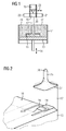
- FIG. 2 a method for producing a rectangular component 15 is shown.
- the surface 19 of the powder bed is shown in sections.
- the laser beam 17 has been widened to a rectangular treatment surface 24, wherein a diffractive optical element is used, which generates a substantially uniform intensity profile over the treatment surface 24, which is indicated by a flat plateau.
- the intensity profile of the laser beam is shown above the treatment surface 24 before passing through the diffractive optical element. It shows a bell-shaped expression of the intensity profile 25 of the laser beam, as this is characteristic of laser beams. This has a pronounced maximum 26 and then drops rapidly to much lower intensity levels to the outside.
- the dot-dashed round base 27 indicates that this intensity profile 25 of the laser beam is rotationally symmetrical.
- the situation is different with the intensity profile produced by the refractive optics, which provides the treatment surface 24. This has a square floor plan.
- the square outline of the treatment surface 24 leads to a movement pattern of the laser 17, which is indicated by the arrow 28.
- the dotted lines on the surface 19 indicate in which grid the treatment surface 24 can be guided over the surface.
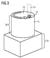
- FIG. 3 the production of another component 15 is indicated. It becomes clear that this component has different regions, wherein the lower part 29 advantageously according to one according to FIG. 2 trained method can be produced.
- the part 30, which is cylindrical, has a cross-sectional area without corners, so that it can be advantageously produced in the surface 19 of the powder bed with a round treatment surface 31.
- a refractive optics is used, which has an intensity profile with a largely constant intensity within the treatment area.
- the component 15 according to FIG. 3 with an installation according to FIG. 1 in which a revolver 20 with a plurality of optics 21, 22, 18 is provided.
Landscapes
- Engineering & Computer Science (AREA)
- Physics & Mathematics (AREA)
- Optics & Photonics (AREA)
- Chemical & Material Sciences (AREA)
- Materials Engineering (AREA)
- Mechanical Engineering (AREA)
- Manufacturing & Machinery (AREA)
- Laser Beam Processing (AREA)
Description
- Die Erfindung betrifft ein Verfahren zum Erzeugen eines Bauteils durch selektives Laserschmelzen, bei dem ein Laserstrahl auf den gerade zu erzeugenden Bereich des in Herstellung befindlichen Bauteils gerichtet wird und dort lokal Partikel des Bauteilwerkstoffs aufgeschmolzen werden. Außerdem betrifft die Erfindung eine Anlage zum selektiven Laserschmelzen, die eine Bauplattform für ein zu erzeugendes Werkstück aufweist und einen Laser, der sich auf die Bauplattform richten lässt.
- Ein Verfahren der eingangs angegebenen Art sowie eine zur Durchführung dieses Verfahrens geeignete Anlage sind beispielsweise aus der
US 7,601,422 B2 allgemein bekannt. Die Anlage weist eine Bauplattform auf, die mit einem Pulver des Bauteilwerkstoffes schichtweise beschickt werden kann. Ein Laser wird über einen Spiegel auf die jeweils gebildete Pulveroberfläche gerichtet, wo die Partikel des Pulvers lokal aufgeschmolzen werden können. In der Anlage werden Daten zur Geometrie des herzustellenden Bauteils verarbeitet, so dass dieses lagenweise im Pulverbett auf der Bauplattform entsteht. Durch die Abtastung der Oberfläche des Pulverbettes mit dem Laserstrahl entsteht prinzipbedingt bei dem Bauteil eine rasterartige bzw. stufige Oberfläche. Die Oberflächengüte kann durch Einstellung der Parameter des Lasers beeinflusst werden, jedoch prinzipbedingt nicht vollständig ausgeglichen werden. - Gemäß der nachveröffentlichten
EP 2 335 848 A1 ist beschrieben, dass der Laserstrahl für ein selektives Laserschmelzen durch Linsenanordnungen so geformt werden kann, dass sich ein quadratisches Intensitätsprofil ergibt. Dieses kann gleichzeitig vergleichmäßigt werden, indem die Bestrahlungsfläche aus neun rechtwinkeligen Teillaserstrahlen aufgebaut wird. - Weitere Verfahren zum Laserschmelzen sind in der
EP 1 405 714 A1 und derUS 2006/019322 A1 beschrieben. Diese Laserschmelzanlagen weisen Einrichtungen auf, mit denen der Durchmesser des Laserstrahls verändert werden kann. Dies wird beispielsweise dadurch bewerkstelligt, dass der Fokuspunkt des Laserstrahls verschoben wird. Damit hat der durch den Durchmesser des Laserstrahls bestimmte Belichtungsbereich jeweils eine unterschiedliche Fläche und Intensität. Der Durchmesser kann in Abhängigkeit des herzustellenden Bauteils in geeigneter Weise variiert werden. - Außerdem ist es aus der
WO 01/91993 A1 - Die Aufgabe der Erfindung besteht darin, ein Verfahren zum Erzeugen eines Bauteils durch selektives Laserschmelzen bzw. eine Anlage, geeignet zum angegebenen Laserschmelzen, anzugeben, mit der sich die Oberflächengüte des hergestellten Bauteils im Vergleich zu herkömmlichen Verfahren verbessern lässt.
- Diese Aufgabe wird mit dem in Anspruch 1 beanspruchten Verfahren und der in Anspruch 4 beanspruchten Anlage gelöst.
- Ein Laserstrahl wird durch ein optisches Element derart geformt, insbesondere aufgeweitet, dass sich in zumindest einer Richtung quer zur Strahlpropagationsrichtung eine Vergleichmäßigung des Intensitätsprofils des Laserlichtes in dem gerade zu erzeugenden Bereich des in Herstellung befindlichen Bauteils ergibt, d.h. ein sogenanntes "Top-Hat-Profil" erzeugt wird. Hierzu ist zu bemerken, dass das Intensitätsprofil eines Laserstrahls an sich eine Intensitätsverteilung aufweist, die durch ein glockenförmiges Profil (Gaussche Verteilung) beschrieben werden kann. Dies bedeutet, dass das Intensitätsmaximum im Zentrum des Laserstrahls liegt und die Intensität zu den Rändern des Laserstrahls hin abnimmt. Hierdurch wird beim Aufschmelzen des Pulverbettes ein Temperaturmaximum in der Mitte des Laserspots auf der Oberfläche des Pulverbettes erreicht, wobei die Temperatur zum Rand hin abnimmt und am Rande nicht zum Aufschmelzen der Partikel ausreicht. Hierdurch werden insbesondere am Rande des aktuell herzustellenden Bauteilquerschnittes an der Oberfläche des Pulverbettes Probleme erzeugt. Der Laserspot muss nämlich am Rande des Querschnitts so lange verweilen, bis die Randpartikel des herzustellenden Bauteils aufgeschmolzen wurden. In der Nähe des Randes, nämlich dort, wo sich das Intensitätsmaximum des Laserstrahls befindet, ist zu diesem Zeitpunkt aber bereits ein zu hohes Maß an Energie zugeführt worden. Daher ist der Prozess insbesondere am Rande des Querschnitts schwer zu beherrschen, und die Gefahr, dass sich hierdurch die Oberflächengüte des Bauteils verschlechtert, ist groß.
- Hier setzt die Erfindung an, indem durch die Formung des Laserstrahls eine Vergleichmäßigung des Intensitätsprofils hervorgerufen wird. Diese erfolgt insbesondere durch bekannte Strahlformungselemente d. h. dass sich das Maximum der Lichtintensität durch die Formung auf einen größeren Flächenbereich des Laserspots verteilt bei gleichzeitiger Verringerung des Intensitätsmaximums. Innerhalb dieses Bereiches wird dann eine gleichmäßig intensive Energiezufuhr in das Pulverbett bewirkt, wodurch ungewollte Temperaturspitzen im Schmelzbad vorteilhaft vermieden werden können.
- Vorteilhaft wird die Strahlformung so ausgelegt, dass die Größe und Form des Bereiches während der Bearbeitung veränderbar ist. Somit kann eine Verkürzung der Prozessgeschwindigkeit erreicht werden ohne die Flexibilität bzgl. der möglichen Strukturgrößen zu verlieren. Insbesondere können durch ein Top-Hat-Profil auch kleinere Strukturen erzeugt werden wie mit einer glockenförmigen Intensitätsverteilung.
- Zu bemerken ist, dass das erzeugte Bauteil Flächenanteile hat, die mehrere der einzeln erzeugten Bauteilschichten enthalten. In diesen Flächenbereichen lässt sich die Oberflächengüte insbesondere dadurch verbessern, dass die zwangsläufig auftretenden Stufen durch die erfindungsgemäße Verfahrensführung regelmäßiger ausgebildet werden, so dass hier das Optimum der Oberflächengüte (bei Verbleib einer gewissen Stufigkeit der Oberfläche) erreicht wird. Bei Oberflächenanteilen des Bauteils, die genau senkrecht zur Strahlrichtung des Laserstrahls liegen, lässt sich ebenfalls eine Verbesserung der Oberflächengüte erreichen. Dies ist dadurch möglich, dass durch die Vergleichmäßigung des Intensitätsprofils des Laserspots auf dem Pulverbett eine Überschneidung der durch den Laser auf der herzustellenden Querschnittsfläche des Bauteils abgefahrenen Bahnen geringer ausfallen kann und hierdurch beispielsweise ein mehrfaches Aufschmelzen der Oberfläche unterbunden wird.
- Ein zusätzlicher Vorteil bei der erfindungsgemäßen Verfahrensführung entsteht auch dadurch, dass die Aufweitung der eingebrachten Strahlungsenergie auf einen größeren Flächenabschnitt des Laserspots auch die Ausbildung von Eigenspannungen im Bauteil verringert. Hierdurch können Nachbehandlungen des Bauteils zum Abbau von Spannungen (beispielsweise Wärmebehandlungen) vorteilhaft abgekürzt werden oder im Produktionsprozess sogar ganz entfallen.
- Gemäß der Erfindung ist außerdem vorgesehen, dass der Laserstrahl durch ein diffraktives optisches Element geformt wird, welches über eine definierte Behandlungsfläche in dem zu erzeugenden Bereich die Vergleichmäßigung des Intensitätsprofils erzeugt. Diffraktive optische Elemente, auch als "Refractive Beam Shapers" bezeichnet, sind an sich bekannt und werden beispielsweise durch die Firma Newport angeboten.
- Diffraktive optische Elemente haben bei ihrem Einsatz den Vorteil, dass sich über eine definierte Fläche ein weitgehend gleichmäßiges Intensitätsprofil einstellen lässt. Hierbei können flächenunterschiedliche Formen, wie beispielsweise quadratische oder runde Flächen, erzeugt werden.
- Gemäß der Erfindung ist es einerseits möglich, dass eine Behandlungsfläche geschaffen wird, die näherungsweise rechteckig, insbesondere quadratisch, ist. Hierdurch lassen sich vorteilhaft insbesondere Bauteile gut herstellen, deren Querschnittsfläche gerade Kanten und insbesondere auch rechtwinklige Ecken aufweisen. Der aufgeweitete Laser kann mit einer der Seitenkanten der Behandlungsfläche direkt am Rand der herzustellenden Querschnittsfläche entlanggeführt werden. Hierbei entsteht im Randbereich des herzustellenden Querschnitts ein gleichmäßiger Energieeintrag, wodurch die Qualität des entstehenden Bauteils vorteilhaft weiter verbessert werden kann. Insbesondere in der Ecke des Querschnitts führt die Verwendung einer rechtwinkligen Behandlungsfläche dazu, dass diese bis in die Ecke hineingefahren werden kann und damit ein gleichmäßiger Energieeintrag im Bereich der Ecke gewährleistet werden kann. Es ist aber auch möglich, dass die Behandlungsfläche näherungsweise oval, insbesondere rund, ist. Mit einer Behandlungsfläche dieser Gestalt können insbesondere Querschnittsflächen des herzustellenden Bauteils erzeugt werden, die eine gekrümmte Außenkontur haben. Der Laser kann dann entlang der gekrümmten Außenkontur geführt werden und dabei tangential immer die Außenkontur berühren, unabhängig davon, welche Winkelstellung der zu erzeugende Teilbereich der Außenkontur in der Ebene des Pulverbettes gerade aufweist.
- Wichtig für die Erfindung ist außerdem, dass je nach Gestalt der auszubildenden Querschnittsfläche zwischen einer rechteckigen, insbesondere quadratischen und einer ovalen, insbesondere runden Behandlungsfläche gewechselt werden kann. Dies ist möglich, weil unterschiedliche refraktive optische Elemente zum Einsatz kommen können, also diese ausgewechselt werden können. Je nach dem, welche Konturbereiche gerade zu fertigen sind, wird dann die besser geeignete Behandlungsfläche ausgewählt. Vorteilhaft ist es, wenn die Intensität des Laserlichtes innerhalb der Behandlungsfläche von einem vorgegebenen Sollwert um weniger als 10 %, bevorzugt weniger als 5 %, abweicht. Hierbei entsteht in dem besagten Bereich vorteilhaft eine sehr gleichmäßige Verteilung des Energieeintrags.
- Mit der eingangs angegebenen Anlage wird die Aufgabe weiterhin dadurch gelöst, dass im Strahlengang des Lasers eine das Intensitätsprofil des Laserlichtes formende Optik angeordnet ist, wobei das erzeugte Intensitätsprofil im Bereich des auf der Bauplattform zu erzeugenden Bauteils liegt. Hierdurch kann sichergestellt werden, dass in dem Bereich, wo das Bauteil oberhalb der Bauplattform lagenweise hergestellt werden soll, die bereits erwähnte Behandlungsfläche erzeugt werden kann. Hierbei lassen sich die bereits erwähnten Vorteile erreichen.
- Erfindungsgemäß wird vorgesehen, dass die Optik als diffraktives optisches Element ausgeführt ist. Hierdurch lassen sich vergleichsweise konstante Lichtintensitäten auf Behandlungsflächen beliebiger geometrischer Formen erzeugen.
- Es ist möglich, dass das diffraktive optische Element eine Strahlaufweitung in eine rechteckige, insbesondere quadratische, Behandlungsfläche vornimmt. Auch eine Strahlaufweitung in eine ovale, insbesondere runde, Behandlungsfläche ist möglich. Die Vorteile dieser Arten von Behandlungsflächen bei der Herstellung von unterschiedlichen Bauteilquerschnitten ist bereits erläutert worden.
- Wichtig für die Erfindung ist außerdem, dass der Strahlengang des Lasers wahlweise durch eines von mehreren diffraktiven optischen Elementen geführt werden kann, wobei durch jedes diffraktive optische Element eine Behandlungsfläche mit einer anderen Geometrie auswählbar ist. Eine solche Anlage kann beispielsweise dadurch realisiert werden, dass unterhalb des Lasers eine Art Bajonett oder Revolver mit unterschiedlichen diffraktiven Optiken vorgesehen wird, die sich jeweils in den Strahlengang des Lasers bringen lassen. Die diffraktiven Optiken können dann wahlweise beispielsweise eine quadratische Behandlungsfläche, eine runde Behandlungsfläche oder auch andere Behandlungsflächen schaffen.
- Eine bevorzugte Ausführungsform der erfindungsgemäßen Anlage wird erhalten, wenn zusätzlich zu der diffraktiven Optik weitere optische Komponenten vorgesehen werden, mit der die Größe der Bearbeitungsfläche eingestellt werden kann, insbesondere in Kombination mit der Möglichkeit einer automatischen Wechselung von verschiedenen diffraktiven Optiken im Strahlengang.
- Weitere Einzelheiten der Erfindung werden nachfolgend anhand der Zeichnung beschrieben. Gleiche oder sich entsprechende Zeichnungselemente sind in den einzelnen Figuren jeweils mit den gleichen Bezugszeichen versehen und werden nur insoweit mehrfach erläutert, wie sich Unterschiede zwischen den einzelnen Figuren ergeben. Es zeigen:
- Figur 1
- die wesentlichen Elemente eines Ausführungsbeispiels der erfindungsgemäßen Anlage zum Laserschmelzen und
- Figur 2 und 3
- Ausführungsbeispiele für das erfindungsgemäße Verfahren.
- Eine Anlage zum selektiven Laserschmelzen gemäß
Figur 1 ist nur in ihren für die Erfindung wesentlichen Bestandteilen dargestellt. Zu erkennen ist ein Behälter 11, in dem ein Pulverbett 12 aus Partikeln bevorratet werden kann. Der Behälter weist als Boden eine Bauplattform 13 auf, welcher in Richtung eines angegebenen Doppelpfeils 14 durch einen nicht dargestellten Antrieb gehoben und abgesenkt werden kann. - In dem Pulverbett 12 kann ein Bauteil 15 lagenweise hergestellt werden, indem ein Laser 16 einen Laserstrahl 17 erzeugt. Dieser wird durch eine Optik 18 geleitet, die in nicht näher dargestellter Weise ein refraktives optisches Element aufweist. Wie zu erkennen ist, wird durch die Optik der Laserstrahl aufgeweitet. Dieser führt an der Oberfläche 19 des Pulverbettes zum Aufschmelzen der Partikel, wodurch das Bauteil 15 lagenweise gebildet wird.
- Die Optik 18 ist Teil eines Bajonetts 20, in dem auch eine Optik 21 und eine Optik 22 untergebracht sind. Mit Hilfe des Bajonetts können mit einem nicht dargestellten Antrieb die unterschiedlichen Optiken 18, 21, 22 ausgewechselt werden. Jede Optik erzeugt eine Strahlaufweitung mit einer anderen Charakteristik, so dass diese an den Anwendungsfall des aktuell herzustellenden Bauteils 15 angepasst werden kann. Der Laser 16 und die Optik 18 (bzw. 21, 22) können in Richtung des angedeuteten Doppelpfeils und senkrecht zur Zeichnungsebene bewegt werden, um die ganze Fläche des Pulverbettes 12 zu überstreichen, je nach dem, wie die Geometrie des herzustellenden Bauteils 15 ausgebildet ist.
- In
Figur 2 ist ein Verfahren zur Erzeugung eines rechtwinkligen Bauteils 15 dargestellt. Die Oberfläche 19 des Pulverbettes ist ausschnitthaft dargestellt. Weiterhin ist zu erkennen, dass der Laserstrahl 17 zu einer rechteckigen Behandlungsfläche 24 aufgeweitet wurde, wobei ein diffraktives optisches Element zum Einsatz kommt, welches über die Behandlungsfläche 24 ein weitgehend gleichmäßiges Intensitätsprofil erzeugt, welches durch ein flaches Plateau angedeutet ist. Zum Vergleich ist oberhalb der Behandlungsfläche 24 das Intensitätsprofil des Laserstrahls vor den Durchtritt durch das diffraktive optische Element dargestellt. Es zeigt sich eine glockenförmige Ausprägung des Intensitätsprofils 25 des Laserstrahls, wie dieses für Laserstrahlen charakteristisch ist. Dieses hat ein stark ausgeprägtes Maximum 26 und fällt dann schnell zu wesentlich geringeren Intensitätswerten nach außen ab. Die strichpunktierte runde Grundfläche 27 deutet an, dass dieses Intensitätsprofil 25 des Laserstrahls rotationssymmetrisch ausgebildet ist. Anders verhält es sich bei dem durch die refraktive Optik hergestellten Intensitätsprofil, welches die Behandlungsfläche 24 zur Verfügung stellt. Dieses hat einen quadratischen Grundriss. - Der quadratische Grundriss der Behandlungsfläche 24 führt zu einem Bewegungsmuster des Lasers 17, welcher durch den Pfeil 28 angedeutet ist. Die strichpunktierten Linien auf der Oberfläche 19 deuten an, in welchem Raster die Behandlungsfläche 24 über die Oberfläche geführt werden kann.
- In
Figur 3 ist die Herstellung eines anderen Bauteils 15 angedeutet. Es wird deutlich, dass dieses Bauteil verschiedene Regionen aufweist, wobei der untere Teil 29 vorteilhaft nach einem gemäßFigur 2 ausgebildeten Verfahren hergestellt werden kann. Der Teil 30, der zylindrisch ist, weist eine Querschnittsfläche ohne Ecken auf, so dass diese in der Oberfläche 19 des Pulverbettes vorteilhaft mit einer runden Behandlungsfläche 31 hergestellt werden kann. Auch hier kommt eine refraktive Optik zum Einsatz, die ein Intensitätsprofil mit einer weitgehenden konstanten Intensität innerhalb der Behandlungsfläche aufweist. Besonders vorteilhaft kann das Bauteil 15 gemäßFigur 3 mit einer Anlage gemäßFigur 1 hergestellt werden, in der ein Revolver 20 mit mehreren Optiken 21, 22, 18 vorgesehen ist.
Claims (4)
- Verfahren zum Erzeugen eines Bauteils (15) durch selektives Laserschmelzen, bei dem ein Laserstrahl (17) auf den gerade zu erzeugenden Bereich des in Herstellung befindlichen Bauteils (15) gerichtet wird und dort lokal Partikel (12) des Bauteilwerkstoffes aufgeschmolzen werden, wobei der Laserstrahl (17) durch ein diffraktives optisches Element derart geformt, insbesondere aufgeweitet wird, dass sich eine Behandlungsfläche ergibt, die in zumindest einer Richtung quer zur Strahlpropagationsrichtung durch eine Vergleichmäßigung des Intensitätsprofils des Laserlichtes in dem gerade zu erzeugenden Bereich des in Herstellung befindlichen Bauteils gebildet ist,
dadurch gekennzeichnet,
dass mehrere wechselbare Optiken (18, 21, 22) verwendet werden, wobei mit dem diffraktiven optischen Element der einen Optik die Behandlungsfläche (24, 31) näherungsweise rechteckig, insbesondere quadratisch erzeugt wird und mit dem diffraktiven optischen Element einer anderen Optik die Behandlungsfläche oval, insbesondere rund erzeugt wird. - Verfahren nach Anspruch 1,
dadurch gekennzeichnet,
dass die Größe der Bearbeitungsfläche (24,31) durch weitere optische Komponenten im Strahlengang variabel eingestellt wird. - Verfahren nach einem der Ansprüche 1 oder 2,
dadurch gekennzeichnet,
dass die Intensität des Laserlichtes innerhalb der Behandlungsfläche (24, 31) von einem vorgegebenen Sollwert um weniger als 10 %, bevorzugt weniger als 5 % abweicht. - Anlage zum selektiven Laserschmelzen, aufweisend• eine Bauplattform (13) für ein zu erzeugendes Werkstück,• einen Laser (16), der sich auf die Bauplattform richten lässt,wobei im Strahlengang des Lasers eine das Intensitätsprofil des Laserlichtes formende Optik (18) angeordnet ist, wobei eine durch das erzeugte Intensitätsprofil gebildete Behandlungsfläche, die in zumindest einer Richtung quer zur Strahlpropagationsrichtung durch eine Vergleichmäßigung des Intensitätsprofils des Laserlichtes in dem gerade zu erzeugenden Bereich des in Herstellung befindlichen Bauteils gebildet ist, im Bereich des auf der Bauplattform zu erzeugenden Bauteils liegt,
dadurch gekennzeichnet,
dass mehrere wechselbare Optiken (18, 21, 22) vorgesehen sind, wobei mit dem diffraktiven optischen Element der einen Optik eine Strahlformung in eine rechteckige, insbesondere quadratische Behandlungsfläche (24, 31) erfolgt und mit dem diffraktiven optischen Element einer anderen Optik eine Strahlformung in eine ovale, insbesondere runde Behandlungsfläche erfolgt.
Applications Claiming Priority (2)
| Application Number | Priority Date | Filing Date | Title |
|---|---|---|---|
| DE102011007067A DE102011007067A1 (de) | 2011-04-08 | 2011-04-08 | Verfahren zum selektiven Laserschmelzen und Anlage zur Durchführung diesen Verfahrens |
| PCT/EP2012/055941 WO2012136615A1 (de) | 2011-04-08 | 2012-04-02 | Verfahren zum selektiven laserschmelzen und anlage zur durchführung dieses verfahrens |
Publications (2)
| Publication Number | Publication Date |
|---|---|
| EP2675609A1 EP2675609A1 (de) | 2013-12-25 |
| EP2675609B1 true EP2675609B1 (de) | 2016-11-02 |
Family
ID=45974286
Family Applications (1)
| Application Number | Title | Priority Date | Filing Date |
|---|---|---|---|
| EP12714631.4A Not-in-force EP2675609B1 (de) | 2011-04-08 | 2012-04-02 | Verfahren zum selektiven laserschmelzen und anlage zur durchführung dieses verfahrens |
Country Status (4)
| Country | Link |
|---|---|
| US (1) | US20140131921A1 (de) |
| EP (1) | EP2675609B1 (de) |
| DE (1) | DE102011007067A1 (de) |
| WO (1) | WO2012136615A1 (de) |
Families Citing this family (3)
| Publication number | Priority date | Publication date | Assignee | Title |
|---|---|---|---|---|
| EP3569388B1 (de) * | 2018-05-15 | 2023-05-03 | Howmedica Osteonics Corp. | Herstellung von komponenten unter verwendung geformter energiestrahlprofile |
| DE102018219032A1 (de) | 2018-08-17 | 2020-02-20 | Denise Bennewitz | Bauteiledruckverfahren und Vorrichtungen hierfür |
| US11679551B2 (en) | 2019-02-28 | 2023-06-20 | General Electric Company | Compensating laser alignment for irregularities in an additive manufacturing machine powderbed |
Family Cites Families (17)
| Publication number | Priority date | Publication date | Assignee | Title |
|---|---|---|---|---|
| US6203861B1 (en) * | 1998-01-12 | 2001-03-20 | University Of Central Florida | One-step rapid manufacturing of metal and composite parts |
| NL1015188C2 (nl) * | 2000-05-12 | 2001-11-13 | Tno | Werkwijze voor het aanbrengen van een ten minste polymeermateriaal bevattende laag. |
| US6544465B1 (en) * | 2000-08-18 | 2003-04-08 | Micron Technology, Inc. | Method for forming three dimensional structures from liquid with improved surface finish |
| US6894712B2 (en) * | 2002-04-10 | 2005-05-17 | Fuji Photo Film Co., Ltd. | Exposure head, exposure apparatus, and application thereof |
| DE10245617A1 (de) * | 2002-09-30 | 2004-04-08 | Eos Gmbh Electro Optical Systems | Vorrichtung und Verfahren zum schichtweisen Herstellen von dreidimensionalen Objekten |
| DE10256097A1 (de) | 2002-12-02 | 2004-06-17 | Eos Gmbh Electro Optical Systems | Kunststoffpulver für das Lasersintern |
| JP2004188604A (ja) * | 2002-12-06 | 2004-07-08 | Ts Corporation | 光学的立体造形装置 |
| DE112004000301B4 (de) * | 2003-02-25 | 2010-05-20 | Panasonic Electric Works Co., Ltd., Kadoma-shi | Verfahren und Vorrichtung zur Herstellung eines dreidimensionalen Objekts |
| DE10309519B4 (de) * | 2003-02-26 | 2006-04-27 | Laserinstitut Mittelsachsen E.V. | Verfahren und Vorrichtung zur Herstellung von Miniaturkörpern oder mikrostrukturierten Körpern |
| DE20318721U1 (de) * | 2003-12-03 | 2005-04-21 | Fockele, Matthias, Dr. | Vorrichtung zur Herstellung eines Formkörpers durch schichtweises Aufbauen aus pulverförmigem, insbesondere metallischem oder keramischem Werkstoff |
| JP4515853B2 (ja) * | 2004-08-04 | 2010-08-04 | ナブテスコ株式会社 | 光学的立体造形装置 |
| US20070072762A1 (en) * | 2005-09-29 | 2007-03-29 | Osram Sylvania Inc. | Method of Making Ceramic Discharge Vessels Using Stereolithography |
| DE102008030186A1 (de) * | 2008-06-26 | 2009-12-31 | Siemens Aktiengesellschaft | Verfahren zum Erzeugen eines Bauteils durch selektives Laserschmelzen sowie hierfür geeignete Prozesskammer |
| GB0816308D0 (en) * | 2008-09-05 | 2008-10-15 | Mtt Technologies Ltd | Optical module |
| EP2292357B1 (de) * | 2009-08-10 | 2016-04-06 | BEGO Bremer Goldschlägerei Wilh.-Herbst GmbH & Co KG | Keramikgegenstand und Verfahren zur Herstellung eines solchen Gegenstands |
| EP2335848B1 (de) * | 2009-12-04 | 2014-08-20 | SLM Solutions GmbH | Optische Bestrahlungseinheit für eine Anlage zur Herstellung von Werkstücken durch Bestrahlen von Pulverschichten mit Laserstrahlung |
| GB2490143B (en) * | 2011-04-20 | 2013-03-13 | Rolls Royce Plc | Method of manufacturing a component |
-
2011
- 2011-04-08 DE DE102011007067A patent/DE102011007067A1/de not_active Withdrawn
-
2012
- 2012-04-02 EP EP12714631.4A patent/EP2675609B1/de not_active Not-in-force
- 2012-04-02 US US14/110,650 patent/US20140131921A1/en not_active Abandoned
- 2012-04-02 WO PCT/EP2012/055941 patent/WO2012136615A1/de active Application Filing
Also Published As
| Publication number | Publication date |
|---|---|
| US20140131921A1 (en) | 2014-05-15 |
| EP2675609A1 (de) | 2013-12-25 |
| DE102011007067A1 (de) | 2012-10-11 |
| WO2012136615A1 (de) | 2012-10-11 |
Similar Documents
| Publication | Publication Date | Title |
|---|---|---|
| EP3221727B1 (de) | System zur asymmetrischen optischen strahlformung | |
| EP3256285B1 (de) | Bestrahlungseinrichtung, bearbeitungsmaschine und verfahren zum herstellen einer schicht bzw. eines teilbereichs einer schicht eines dreidimensionalen bauteils | |
| DE60120905T2 (de) | Optisches System mit elektronischer Punktgrössensteuerung und Fokussierungskontrolle | |
| DE102019128362B3 (de) | Segmentiertes Strahlformungselement und Laserbearbeitungsanlage | |
| DE19746483C5 (de) | Vorrichtung zur Formgebung von optischen Linsen durch Materialabtrag | |
| EP3519126B1 (de) | Herstellen dreidimensionaler werkstücke mittels einer mehrzahl von bestrahlungseinheiten | |
| EP3242762A1 (de) | Vorrichtung und generatives schichtbauverfahren zur herstellung eines dreidimensionalen objekts mit mehrzahligen strahlen | |
| EP3799999A1 (de) | Optisches system zur strahlformung | |
| EP3752314A1 (de) | Verfahren und vorrichtung zum einfügen einer trennlinie in ein transparentes sprödbrüchiges material, sowie verfahrensgemäss herstellbares, mit einer trennlinie versehenes element | |
| WO2015032926A1 (de) | Verfahren zur bearbeitung eines werkstücks mittels eines laserstrahls, laserwerkzeug, lasermaschine, maschinensteuerung | |
| EP3017895A1 (de) | Herstellen eines bauteils durch selektives laserschmelzen | |
| WO2011066989A1 (de) | Optische bestrahlungseinheit für eine anlage zur herstellung von werkstücken durch bestrahlen von pulverschichten mit laserstrahlung | |
| EP3414044B1 (de) | Verfahren zum herstellen mindestens eines teilbereichs einer schicht eines dreidimensionalen bauteils | |
| WO2010130255A1 (de) | Vorrichtung und verfahren zur umfangsbearbeitung eines materialstranges mittels laser | |
| DE102019125103A1 (de) | Bearbeitungsvorrichtung zur Laserbearbeitung eines Werkstücks, Verfahren zur Laserbearbeitung eines Werkstücks | |
| EP2675609B1 (de) | Verfahren zum selektiven laserschmelzen und anlage zur durchführung dieses verfahrens | |
| DE102016213420A1 (de) | Verfahren und Vorrichtung zum generativen Herstellen eines Bauteils | |
| EP1479506B1 (de) | Laserfügeverfahren für strukturierte Kunststoffe | |
| DE29724852U1 (de) | Vorrichtung zur Formgebung von Objekten | |
| DE102019135283A1 (de) | Verfahren zur Lasermaterialbearbeitung und Laserbearbeitungsanlage | |
| WO2019034259A1 (de) | Vefahren zur bearbeitung einer werkstoffschicht mit energetischer strahlung variabler energieverteilung | |
| DE112017006002T5 (de) | Laserstrahlbearbeitungsverfahren und Laserstrahlmaschine | |
| DE102015113141A1 (de) | Verfahren zur Bearbeitung einer Werkstückoberfläche und Werkstück | |
| DE112014007256T5 (de) | Systeme sowie Verfahren zum Schweißen unter Verwendung von Strahlformmitteln und Abschirmmitteln | |
| EP3702132B1 (de) | Verfahren zur lithographiebasierten generativen fertigung eines dreidimensionalen bauteils |
Legal Events
| Date | Code | Title | Description |
|---|---|---|---|
| PUAI | Public reference made under article 153(3) epc to a published international application that has entered the european phase |
Free format text: ORIGINAL CODE: 0009012 |
|
| 17P | Request for examination filed |
Effective date: 20130917 |
|
| AK | Designated contracting states |
Kind code of ref document: A1 Designated state(s): AL AT BE BG CH CY CZ DE DK EE ES FI FR GB GR HR HU IE IS IT LI LT LU LV MC MK MT NL NO PL PT RO RS SE SI SK SM TR |
|
| DAX | Request for extension of the european patent (deleted) | ||
| 17Q | First examination report despatched |
Effective date: 20150803 |
|
| GRAP | Despatch of communication of intention to grant a patent |
Free format text: ORIGINAL CODE: EPIDOSNIGR1 |
|
| INTG | Intention to grant announced |
Effective date: 20160420 |
|
| GRAP | Despatch of communication of intention to grant a patent |
Free format text: ORIGINAL CODE: EPIDOSNIGR1 |
|
| INTG | Intention to grant announced |
Effective date: 20160523 |
|
| GRAS | Grant fee paid |
Free format text: ORIGINAL CODE: EPIDOSNIGR3 |
|
| GRAA | (expected) grant |
Free format text: ORIGINAL CODE: 0009210 |
|
| AK | Designated contracting states |
Kind code of ref document: B1 Designated state(s): AL AT BE BG CH CY CZ DE DK EE ES FI FR GB GR HR HU IE IS IT LI LT LU LV MC MK MT NL NO PL PT RO RS SE SI SK SM TR |
|
| REG | Reference to a national code |
Ref country code: GB Ref legal event code: FG4D Free format text: NOT ENGLISH |
|
| REG | Reference to a national code |
Ref country code: AT Ref legal event code: REF Ref document number: 841386 Country of ref document: AT Kind code of ref document: T Effective date: 20161115 Ref country code: CH Ref legal event code: EP |
|
| REG | Reference to a national code |
Ref country code: DE Ref legal event code: R079 Ref document number: 502012008676 Country of ref document: DE Free format text: PREVIOUS MAIN CLASS: B29C0067000000 Ipc: B29C0064106000 |
|
| REG | Reference to a national code |
Ref country code: IE Ref legal event code: FG4D Free format text: LANGUAGE OF EP DOCUMENT: GERMAN |
|
| REG | Reference to a national code |
Ref country code: CH Ref legal event code: NV Representative=s name: SIEMENS SCHWEIZ AG, CH Ref country code: DE Ref legal event code: R096 Ref document number: 502012008676 Country of ref document: DE |
|
| PG25 | Lapsed in a contracting state [announced via postgrant information from national office to epo] |
Ref country code: LV Free format text: LAPSE BECAUSE OF FAILURE TO SUBMIT A TRANSLATION OF THE DESCRIPTION OR TO PAY THE FEE WITHIN THE PRESCRIBED TIME-LIMIT Effective date: 20161102 |
|
| REG | Reference to a national code |
Ref country code: NL Ref legal event code: MP Effective date: 20161102 |
|
| REG | Reference to a national code |
Ref country code: LT Ref legal event code: MG4D |
|
| REG | Reference to a national code |
Ref country code: FR Ref legal event code: PLFP Year of fee payment: 6 |
|
| PG25 | Lapsed in a contracting state [announced via postgrant information from national office to epo] |
Ref country code: SE Free format text: LAPSE BECAUSE OF FAILURE TO SUBMIT A TRANSLATION OF THE DESCRIPTION OR TO PAY THE FEE WITHIN THE PRESCRIBED TIME-LIMIT Effective date: 20161102 Ref country code: NL Free format text: LAPSE BECAUSE OF FAILURE TO SUBMIT A TRANSLATION OF THE DESCRIPTION OR TO PAY THE FEE WITHIN THE PRESCRIBED TIME-LIMIT Effective date: 20161102 Ref country code: LT Free format text: LAPSE BECAUSE OF FAILURE TO SUBMIT A TRANSLATION OF THE DESCRIPTION OR TO PAY THE FEE WITHIN THE PRESCRIBED TIME-LIMIT Effective date: 20161102 Ref country code: GR Free format text: LAPSE BECAUSE OF FAILURE TO SUBMIT A TRANSLATION OF THE DESCRIPTION OR TO PAY THE FEE WITHIN THE PRESCRIBED TIME-LIMIT Effective date: 20170203 Ref country code: NO Free format text: LAPSE BECAUSE OF FAILURE TO SUBMIT A TRANSLATION OF THE DESCRIPTION OR TO PAY THE FEE WITHIN THE PRESCRIBED TIME-LIMIT Effective date: 20170202 |
|
| PG25 | Lapsed in a contracting state [announced via postgrant information from national office to epo] |
Ref country code: HR Free format text: LAPSE BECAUSE OF FAILURE TO SUBMIT A TRANSLATION OF THE DESCRIPTION OR TO PAY THE FEE WITHIN THE PRESCRIBED TIME-LIMIT Effective date: 20161102 Ref country code: FI Free format text: LAPSE BECAUSE OF FAILURE TO SUBMIT A TRANSLATION OF THE DESCRIPTION OR TO PAY THE FEE WITHIN THE PRESCRIBED TIME-LIMIT Effective date: 20161102 Ref country code: RS Free format text: LAPSE BECAUSE OF FAILURE TO SUBMIT A TRANSLATION OF THE DESCRIPTION OR TO PAY THE FEE WITHIN THE PRESCRIBED TIME-LIMIT Effective date: 20161102 Ref country code: PT Free format text: LAPSE BECAUSE OF FAILURE TO SUBMIT A TRANSLATION OF THE DESCRIPTION OR TO PAY THE FEE WITHIN THE PRESCRIBED TIME-LIMIT Effective date: 20170302 Ref country code: ES Free format text: LAPSE BECAUSE OF FAILURE TO SUBMIT A TRANSLATION OF THE DESCRIPTION OR TO PAY THE FEE WITHIN THE PRESCRIBED TIME-LIMIT Effective date: 20161102 Ref country code: PL Free format text: LAPSE BECAUSE OF FAILURE TO SUBMIT A TRANSLATION OF THE DESCRIPTION OR TO PAY THE FEE WITHIN THE PRESCRIBED TIME-LIMIT Effective date: 20161102 Ref country code: IS Free format text: LAPSE BECAUSE OF FAILURE TO SUBMIT A TRANSLATION OF THE DESCRIPTION OR TO PAY THE FEE WITHIN THE PRESCRIBED TIME-LIMIT Effective date: 20170302 |
|
| PG25 | Lapsed in a contracting state [announced via postgrant information from national office to epo] |
Ref country code: EE Free format text: LAPSE BECAUSE OF FAILURE TO SUBMIT A TRANSLATION OF THE DESCRIPTION OR TO PAY THE FEE WITHIN THE PRESCRIBED TIME-LIMIT Effective date: 20161102 Ref country code: CZ Free format text: LAPSE BECAUSE OF FAILURE TO SUBMIT A TRANSLATION OF THE DESCRIPTION OR TO PAY THE FEE WITHIN THE PRESCRIBED TIME-LIMIT Effective date: 20161102 Ref country code: RO Free format text: LAPSE BECAUSE OF FAILURE TO SUBMIT A TRANSLATION OF THE DESCRIPTION OR TO PAY THE FEE WITHIN THE PRESCRIBED TIME-LIMIT Effective date: 20161102 Ref country code: SK Free format text: LAPSE BECAUSE OF FAILURE TO SUBMIT A TRANSLATION OF THE DESCRIPTION OR TO PAY THE FEE WITHIN THE PRESCRIBED TIME-LIMIT Effective date: 20161102 Ref country code: DK Free format text: LAPSE BECAUSE OF FAILURE TO SUBMIT A TRANSLATION OF THE DESCRIPTION OR TO PAY THE FEE WITHIN THE PRESCRIBED TIME-LIMIT Effective date: 20161102 |
|
| REG | Reference to a national code |
Ref country code: DE Ref legal event code: R097 Ref document number: 502012008676 Country of ref document: DE |
|
| RAP2 | Party data changed (patent owner data changed or rights of a patent transferred) |
Owner name: SIEMENS AKTIENGESELLSCHAFT |
|
| PG25 | Lapsed in a contracting state [announced via postgrant information from national office to epo] |
Ref country code: BG Free format text: LAPSE BECAUSE OF FAILURE TO SUBMIT A TRANSLATION OF THE DESCRIPTION OR TO PAY THE FEE WITHIN THE PRESCRIBED TIME-LIMIT Effective date: 20170202 Ref country code: IT Free format text: LAPSE BECAUSE OF FAILURE TO SUBMIT A TRANSLATION OF THE DESCRIPTION OR TO PAY THE FEE WITHIN THE PRESCRIBED TIME-LIMIT Effective date: 20161102 Ref country code: SM Free format text: LAPSE BECAUSE OF FAILURE TO SUBMIT A TRANSLATION OF THE DESCRIPTION OR TO PAY THE FEE WITHIN THE PRESCRIBED TIME-LIMIT Effective date: 20161102 |
|
| PLBE | No opposition filed within time limit |
Free format text: ORIGINAL CODE: 0009261 |
|
| STAA | Information on the status of an ep patent application or granted ep patent |
Free format text: STATUS: NO OPPOSITION FILED WITHIN TIME LIMIT |
|
| REG | Reference to a national code |
Ref country code: CH Ref legal event code: PCOW Free format text: NEW ADDRESS: WERNER-VON-SIEMENS-STRASSE 1, 80333 MUENCHEN (DE) |
|
| 26N | No opposition filed |
Effective date: 20170803 |
|
| PG25 | Lapsed in a contracting state [announced via postgrant information from national office to epo] |
Ref country code: SI Free format text: LAPSE BECAUSE OF FAILURE TO SUBMIT A TRANSLATION OF THE DESCRIPTION OR TO PAY THE FEE WITHIN THE PRESCRIBED TIME-LIMIT Effective date: 20161102 |
|
| REG | Reference to a national code |
Ref country code: IE Ref legal event code: MM4A |
|
| PG25 | Lapsed in a contracting state [announced via postgrant information from national office to epo] |
Ref country code: MC Free format text: LAPSE BECAUSE OF FAILURE TO SUBMIT A TRANSLATION OF THE DESCRIPTION OR TO PAY THE FEE WITHIN THE PRESCRIBED TIME-LIMIT Effective date: 20161102 |
|
| PG25 | Lapsed in a contracting state [announced via postgrant information from national office to epo] |
Ref country code: LU Free format text: LAPSE BECAUSE OF NON-PAYMENT OF DUE FEES Effective date: 20170402 |
|
| REG | Reference to a national code |
Ref country code: BE Ref legal event code: MM Effective date: 20170430 |
|
| REG | Reference to a national code |
Ref country code: FR Ref legal event code: PLFP Year of fee payment: 7 |
|
| PG25 | Lapsed in a contracting state [announced via postgrant information from national office to epo] |
Ref country code: IE Free format text: LAPSE BECAUSE OF NON-PAYMENT OF DUE FEES Effective date: 20170402 |
|
| PG25 | Lapsed in a contracting state [announced via postgrant information from national office to epo] |
Ref country code: BE Free format text: LAPSE BECAUSE OF NON-PAYMENT OF DUE FEES Effective date: 20170430 |
|
| REG | Reference to a national code |
Ref country code: AT Ref legal event code: MM01 Ref document number: 841386 Country of ref document: AT Kind code of ref document: T Effective date: 20170402 |
|
| PG25 | Lapsed in a contracting state [announced via postgrant information from national office to epo] |
Ref country code: AT Free format text: LAPSE BECAUSE OF NON-PAYMENT OF DUE FEES Effective date: 20170402 |
|
| PG25 | Lapsed in a contracting state [announced via postgrant information from national office to epo] |
Ref country code: MT Free format text: LAPSE BECAUSE OF FAILURE TO SUBMIT A TRANSLATION OF THE DESCRIPTION OR TO PAY THE FEE WITHIN THE PRESCRIBED TIME-LIMIT Effective date: 20161102 |
|
| PG25 | Lapsed in a contracting state [announced via postgrant information from national office to epo] |
Ref country code: HU Free format text: LAPSE BECAUSE OF FAILURE TO SUBMIT A TRANSLATION OF THE DESCRIPTION OR TO PAY THE FEE WITHIN THE PRESCRIBED TIME-LIMIT; INVALID AB INITIO Effective date: 20120402 |
|
| PGFP | Annual fee paid to national office [announced via postgrant information from national office to epo] |
Ref country code: DE Payment date: 20190617 Year of fee payment: 8 |
|
| PGFP | Annual fee paid to national office [announced via postgrant information from national office to epo] |
Ref country code: FR Payment date: 20190425 Year of fee payment: 8 |
|
| PG25 | Lapsed in a contracting state [announced via postgrant information from national office to epo] |
Ref country code: CY Free format text: LAPSE BECAUSE OF NON-PAYMENT OF DUE FEES Effective date: 20161102 |
|
| PGFP | Annual fee paid to national office [announced via postgrant information from national office to epo] |
Ref country code: GB Payment date: 20190402 Year of fee payment: 8 |
|
| PG25 | Lapsed in a contracting state [announced via postgrant information from national office to epo] |
Ref country code: MK Free format text: LAPSE BECAUSE OF FAILURE TO SUBMIT A TRANSLATION OF THE DESCRIPTION OR TO PAY THE FEE WITHIN THE PRESCRIBED TIME-LIMIT Effective date: 20161102 |
|
| PGFP | Annual fee paid to national office [announced via postgrant information from national office to epo] |
Ref country code: CH Payment date: 20190702 Year of fee payment: 8 |
|
| PG25 | Lapsed in a contracting state [announced via postgrant information from national office to epo] |
Ref country code: TR Free format text: LAPSE BECAUSE OF FAILURE TO SUBMIT A TRANSLATION OF THE DESCRIPTION OR TO PAY THE FEE WITHIN THE PRESCRIBED TIME-LIMIT Effective date: 20161102 |
|
| PG25 | Lapsed in a contracting state [announced via postgrant information from national office to epo] |
Ref country code: AL Free format text: LAPSE BECAUSE OF FAILURE TO SUBMIT A TRANSLATION OF THE DESCRIPTION OR TO PAY THE FEE WITHIN THE PRESCRIBED TIME-LIMIT Effective date: 20161102 |
|
| REG | Reference to a national code |
Ref country code: DE Ref legal event code: R119 Ref document number: 502012008676 Country of ref document: DE |
|
| REG | Reference to a national code |
Ref country code: CH Ref legal event code: PL |
|
| PG25 | Lapsed in a contracting state [announced via postgrant information from national office to epo] |
Ref country code: CH Free format text: LAPSE BECAUSE OF NON-PAYMENT OF DUE FEES Effective date: 20200430 Ref country code: LI Free format text: LAPSE BECAUSE OF NON-PAYMENT OF DUE FEES Effective date: 20200430 Ref country code: FR Free format text: LAPSE BECAUSE OF NON-PAYMENT OF DUE FEES Effective date: 20200430 Ref country code: DE Free format text: LAPSE BECAUSE OF NON-PAYMENT OF DUE FEES Effective date: 20201103 |
|
| GBPC | Gb: european patent ceased through non-payment of renewal fee |
Effective date: 20200402 |
|
| PG25 | Lapsed in a contracting state [announced via postgrant information from national office to epo] |
Ref country code: GB Free format text: LAPSE BECAUSE OF NON-PAYMENT OF DUE FEES Effective date: 20200402 |